EP2644410A2 - A bead structure for a tire - Google Patents
A bead structure for a tire Download PDFInfo
- Publication number
- EP2644410A2 EP2644410A2 EP13160882.0A EP13160882A EP2644410A2 EP 2644410 A2 EP2644410 A2 EP 2644410A2 EP 13160882 A EP13160882 A EP 13160882A EP 2644410 A2 EP2644410 A2 EP 2644410A2
- Authority
- EP
- European Patent Office
- Prior art keywords
- tire
- resin
- fibers
- previous
- impregnated fabric
- Prior art date
- Legal status (The legal status is an assumption and is not a legal conclusion. Google has not performed a legal analysis and makes no representation as to the accuracy of the status listed.)
- Withdrawn
Links
Images

Classifications
-
- B—PERFORMING OPERATIONS; TRANSPORTING
- B60—VEHICLES IN GENERAL
- B60C—VEHICLE TYRES; TYRE INFLATION; TYRE CHANGING; CONNECTING VALVES TO INFLATABLE ELASTIC BODIES IN GENERAL; DEVICES OR ARRANGEMENTS RELATED TO TYRES
- B60C15/00—Tyre beads, e.g. ply turn-up or overlap
- B60C15/04—Bead cores
-
- B—PERFORMING OPERATIONS; TRANSPORTING
- B29—WORKING OF PLASTICS; WORKING OF SUBSTANCES IN A PLASTIC STATE IN GENERAL
- B29D—PRODUCING PARTICULAR ARTICLES FROM PLASTICS OR FROM SUBSTANCES IN A PLASTIC STATE
- B29D30/00—Producing pneumatic or solid tyres or parts thereof
- B29D30/06—Pneumatic tyres or parts thereof (e.g. produced by casting, moulding, compression moulding, injection moulding, centrifugal casting)
- B29D30/48—Bead-rings or bead-cores; Treatment thereof prior to building the tyre
-
- B—PERFORMING OPERATIONS; TRANSPORTING
- B60—VEHICLES IN GENERAL
- B60C—VEHICLE TYRES; TYRE INFLATION; TYRE CHANGING; CONNECTING VALVES TO INFLATABLE ELASTIC BODIES IN GENERAL; DEVICES OR ARRANGEMENTS RELATED TO TYRES
- B60C11/00—Tyre tread bands; Tread patterns; Anti-skid inserts
- B60C11/03—Tread patterns
- B60C11/04—Tread patterns in which the raised area of the pattern consists only of continuous circumferential ribs, e.g. zig-zag
-
- B—PERFORMING OPERATIONS; TRANSPORTING
- B60—VEHICLES IN GENERAL
- B60C—VEHICLE TYRES; TYRE INFLATION; TYRE CHANGING; CONNECTING VALVES TO INFLATABLE ELASTIC BODIES IN GENERAL; DEVICES OR ARRANGEMENTS RELATED TO TYRES
- B60C15/00—Tyre beads, e.g. ply turn-up or overlap
- B60C15/06—Flipper strips, fillers, or chafing strips and reinforcing layers for the construction of the bead
- B60C15/0603—Flipper strips, fillers, or chafing strips and reinforcing layers for the construction of the bead characterised by features of the bead filler or apex
-
- B—PERFORMING OPERATIONS; TRANSPORTING
- B60—VEHICLES IN GENERAL
- B60C—VEHICLE TYRES; TYRE INFLATION; TYRE CHANGING; CONNECTING VALVES TO INFLATABLE ELASTIC BODIES IN GENERAL; DEVICES OR ARRANGEMENTS RELATED TO TYRES
- B60C15/00—Tyre beads, e.g. ply turn-up or overlap
- B60C15/06—Flipper strips, fillers, or chafing strips and reinforcing layers for the construction of the bead
- B60C15/0628—Flipper strips, fillers, or chafing strips and reinforcing layers for the construction of the bead comprising a bead reinforcing layer
- B60C15/0632—Flipper strips, fillers, or chafing strips and reinforcing layers for the construction of the bead comprising a bead reinforcing layer using flippers in contact with and wrapped around the bead core and, at least partially, in contact with the bead filler
-
- B—PERFORMING OPERATIONS; TRANSPORTING
- B60—VEHICLES IN GENERAL
- B60C—VEHICLE TYRES; TYRE INFLATION; TYRE CHANGING; CONNECTING VALVES TO INFLATABLE ELASTIC BODIES IN GENERAL; DEVICES OR ARRANGEMENTS RELATED TO TYRES
- B60C15/00—Tyre beads, e.g. ply turn-up or overlap
- B60C15/06—Flipper strips, fillers, or chafing strips and reinforcing layers for the construction of the bead
- B60C15/0628—Flipper strips, fillers, or chafing strips and reinforcing layers for the construction of the bead comprising a bead reinforcing layer
- B60C15/0635—Flipper strips, fillers, or chafing strips and reinforcing layers for the construction of the bead comprising a bead reinforcing layer using chippers between the carcass layer and chafer rubber wrapped around the bead
-
- B—PERFORMING OPERATIONS; TRANSPORTING
- B60—VEHICLES IN GENERAL
- B60C—VEHICLE TYRES; TYRE INFLATION; TYRE CHANGING; CONNECTING VALVES TO INFLATABLE ELASTIC BODIES IN GENERAL; DEVICES OR ARRANGEMENTS RELATED TO TYRES
- B60C11/00—Tyre tread bands; Tread patterns; Anti-skid inserts
- B60C11/03—Tread patterns
- B60C2011/0337—Tread patterns characterised by particular design features of the pattern
- B60C2011/0339—Grooves
- B60C2011/0341—Circumferential grooves
- B60C2011/0348—Narrow grooves, i.e. having a width of less than 4 mm
-
- B—PERFORMING OPERATIONS; TRANSPORTING
- B60—VEHICLES IN GENERAL
- B60C—VEHICLE TYRES; TYRE INFLATION; TYRE CHANGING; CONNECTING VALVES TO INFLATABLE ELASTIC BODIES IN GENERAL; DEVICES OR ARRANGEMENTS RELATED TO TYRES
- B60C11/00—Tyre tread bands; Tread patterns; Anti-skid inserts
- B60C11/03—Tread patterns
- B60C11/12—Tread patterns characterised by the use of narrow slits or incisions, e.g. sipes
- B60C11/1204—Tread patterns characterised by the use of narrow slits or incisions, e.g. sipes with special shape of the sipe
- B60C2011/1209—Tread patterns characterised by the use of narrow slits or incisions, e.g. sipes with special shape of the sipe straight at the tread surface
-
- B—PERFORMING OPERATIONS; TRANSPORTING
- B60—VEHICLES IN GENERAL
- B60C—VEHICLE TYRES; TYRE INFLATION; TYRE CHANGING; CONNECTING VALVES TO INFLATABLE ELASTIC BODIES IN GENERAL; DEVICES OR ARRANGEMENTS RELATED TO TYRES
- B60C15/00—Tyre beads, e.g. ply turn-up or overlap
- B60C15/04—Bead cores
- B60C2015/042—Bead cores characterised by the material of the core, e.g. alloy
-
- B—PERFORMING OPERATIONS; TRANSPORTING
- B60—VEHICLES IN GENERAL
- B60C—VEHICLE TYRES; TYRE INFLATION; TYRE CHANGING; CONNECTING VALVES TO INFLATABLE ELASTIC BODIES IN GENERAL; DEVICES OR ARRANGEMENTS RELATED TO TYRES
- B60C15/00—Tyre beads, e.g. ply turn-up or overlap
- B60C15/06—Flipper strips, fillers, or chafing strips and reinforcing layers for the construction of the bead
- B60C2015/0617—Flipper strips, fillers, or chafing strips and reinforcing layers for the construction of the bead comprising a cushion rubber other than the chafer or clinch rubber
- B60C2015/0621—Flipper strips, fillers, or chafing strips and reinforcing layers for the construction of the bead comprising a cushion rubber other than the chafer or clinch rubber adjacent to the carcass turnup portion
Definitions
- the present invention relates to tires and, more specifically, to bead structures of tires such as pneumatic tires.
- the tires may be truck or passenger tires.
- beads in tires are known for a long time. Such beads are made of a metal such as steel.
- the tire bead also contributes to the rolling resistance of the tire. Hence, there is a need provide a tire bead with improved rolling resistance of the tire.
- the invention relates to a tire in accordance with claim 1 and to a method in accordance with claim 14.
- Dependent claims refer to preferred embodiments of the invention.
- a pneumatic tire in accordance with a preferred aspect of the present invention includes a tread extending circumferentially around an outer portion of the pneumatic tire; two sidewalls extending radially inward from the tread; a carcass ply extending radially inward through each sidewall; two annular bead portions securing radially inner portions of the carcass ply; and two apexes extending radially outward from each bead portion.
- the bead portions include a composite material constructed of resin-impregnated fabric layers including a resin, a hardener, an accelerator, and fibers.
- the fibers are glass fibers.
- the fibers are carbon fibers.
- the fibers comprise both glass fibers and carbon fibers.
- the apexes comprise a composite material constructed of resin-impregnated fabric layers including a resin, a hardener, an accelerator, and fibers.
- each bead portion comprises an integral structure with an associated apex.
- the uncured bead portions form a first liquid component mixture wherein for 0.1 kg resin between 0.012 kg and 0.018 kg hardener and between 0.003 kg and 0.007 kg accelerator is added.
- the integral structure forms a first liquid component mixture having for a weight of 0.1 kg resin between 0.012 kg and 0.018 kg hardener and between 0.003 kg and 0.007 kg accelerator.
- the resin-impregnated fabric layers are manufactured into a final shape of the bead portions.
- the resin-impregnated fabric layers are cut and placed one above the other into a mold that corresponds to the dimensions of the bead portions.
- the fibers may have circular cross-sections.
- the fibers may have rectangular cross-sections.
- the fibers may have triangular cross-sections.
- the fibers may be are oriented radially.
- the fibers may be are oriented axially.
- the fibers may be are oriented circumferentially.
- Axial and “axially” means lines or directions that are parallel to the axis of rotation of the tire.
- “Circumferential” means lines or directions extending along the perimeter of the surface of the annular tread perpendicular to the axial direction.
- FIGS. 1 and 2 show an example tire 10 for use with the present invention.
- the tire 10 has a tread 20 and a casing 12.
- the casing 12 has two sidewalls, one or more radial plies 88 extending from, and wrapped about, two annular beads 13, and a belt reinforcement structure 15 located radially between the tread 20 and the ply or plies 88.
- the plies 88 and the belt reinforcement structure 15 may be cord reinforced elastomeric material.
- the cords may be, for example, steel wire filaments and the elastomer may be, for example, a vulcanized rubber material.
- the annular beads 13 have steel wires wrapped into a bundle forming an inextensible bead core.
- An innerliner component 19, for example a halobutyl rubber, may form a somewhat air impervious chamber to contain the air pressure when the tire 10 is inflated.
- the tire 10 may further include an elastomeric apex 61 radially disposed above each bead 13.
- a turnup 21 of the ply 88 in each bead area may be reinforced with a flipper 62, a chipper 63, a gum and fabric chafer 64, a gum strip 66, and/or elastomeric wedges 67.
- the belt reinforcement structure 15 may include a gum strip of rubber material 72 and/or a plurality of elastomeric strips or wedges 74 in the lateral extremes or edges of the belt reinforcement structure 15 in proximity of the lateral shoulders of the tread 20.
- the example tread 20 may have a predetermined non-skid depth and four circumferential grooves including two centerline grooves 14 and two shoulder grooves 16 that divide the tread 20 into five circumferential ribs 18.
- the shoulder grooves 16 may have a greater width than the centerline grooves 14 thereby mitigating groove cracking.
- the narrower centerline grooves 14 may optimize rolling resistance and pressure distribution throughout the tread 20.
- Laterally extending blind sipes 100 may extend at least partially across the five ribs 18 of the tread 20 to form five circumferentially extending ribs 18 including two shoulder ribs 24, two riding ribs 26, and a center rib 28. Further, one end of the blind sipes 100 may be enclosed within the edges of the ribs 18 for optimizing wetskid performance.
- the beads 13 and/or apexes 61 comprise a fiber composite material constructed of resin-impregnated fiber or fabric layers. Accordingly, the beads 13 and/or apexes 61 comprise a resin, a hardener, an accelerator, and fibers of glass and/or carbon.
- the uncured beads 13 and/or apexes 61 may form a first liquid component mixture having for a weight of 0.1 kg resin 0.012 kg to 0.018 kg hardener and 0.003 kg to 0.007 kg accelerator, or equivalent ratio.
- Each bead 13 and apex 61 may also be a single piece constructed in accordance with the present invention.
- the beads 13 and/or apexes 61 accordingly are similar in composition to so called “Prepregs” used as springs and may be manufactured in the same way as such Prepregs.
- Prepregs so called "Prepregs” used as springs and may be manufactured in the same way as such Prepregs.
- Prepregs which may be used to manufacture the beads 13 and/or apexes 61 in accordance with the invention are also described in DE 10 2006 052 137 A1 .
- Such fiber composite beads 13 and/or apexes 61 may be produced from resin-impregnated fiber layers.
- These resin-impregnated fiber layers may be manufactured in the desired shape and/or cut and placed one above the other into a mold that corresponds to the dimensions of the beads 13 and/or apexes 61. Unfinished beads 13 and/or apexes 61 may be placed in the mold under the action of pressure and heat cured.
- the resin-impregnated fibers and resin-impregnated fiber layers may be variously sized and oriented.
- the fibers may be oriented radially away from, axially along, or circumferentially relative to the axis of rotation of the beads 13. All or a portion of the fibers may be cylindrical, rectangular, triangular, etc. Fibers may be 10.0 mm in length up to the entire circumference of the beads 13. Cross-sectional areas of the fibers may also be constant or vary.
- the relationship between the fibers and resin may be such that the beads 13 and/apexes 61 may withstand extreme stresses occurring during the tire's operation and maximum service life.
- the bead construction in accordance with this invention allows the manufacture of lighter tire compared to steel bead at equal strength. It also allows to reduce the bead size at equal strength.
- the bead construction in accordance with this invention also gives the tire designer a new degree of freedom in tire design. Finally, the bead construction in accordance with this invention may improve rolling resistance of the tire.
Abstract
Description
- The present invention relates to tires and, more specifically, to bead structures of tires such as pneumatic tires. The tires may be truck or passenger tires.
- The use of beads in tires is known for a long time. Such beads are made of a metal such as steel.
- A challenge exists to provide a tire with a lighter and/or smaller bead to safe tire weight and cost.
- The tire bead also contributes to the rolling resistance of the tire. Hence, there is a need provide a tire bead with improved rolling resistance of the tire.
- The invention relates to a tire in accordance with claim 1 and to a method in accordance with
claim 14. Dependent claims refer to preferred embodiments of the invention. - A pneumatic tire in accordance with a preferred aspect of the present invention includes a tread extending circumferentially around an outer portion of the pneumatic tire; two sidewalls extending radially inward from the tread; a carcass ply extending radially inward through each sidewall; two annular bead portions securing radially inner portions of the carcass ply; and two apexes extending radially outward from each bead portion. The bead portions include a composite material constructed of resin-impregnated fabric layers including a resin, a hardener, an accelerator, and fibers.
- According to another preferred aspect of the tire, the fibers are glass fibers.
- According to still another preferred aspect of the tire, the fibers are carbon fibers.
- According to yet another preferred aspect of the tire, the fibers comprise both glass fibers and carbon fibers.
- According to still another preferred aspect of the tire, the apexes comprise a composite material constructed of resin-impregnated fabric layers including a resin, a hardener, an accelerator, and fibers.
- According to yet another preferred aspect of the tire, each bead portion comprises an integral structure with an associated apex.
- According to still another preferred aspect of the tire, the uncured bead portions form a first liquid component mixture wherein for 0.1 kg resin between 0.012 kg and 0.018 kg hardener and between 0.003 kg and 0.007 kg accelerator is added.
- According to yet another preferred aspect of the tire, the integral structure forms a first liquid component mixture having for a weight of 0.1 kg resin between 0.012 kg and 0.018 kg hardener and between 0.003 kg and 0.007 kg accelerator.
- According to still another preferred aspect of the tire, the resin-impregnated fabric layers are manufactured into a final shape of the bead portions.
- According to yet another preferred aspect of the tire, the resin-impregnated fabric layers are cut and placed one above the other into a mold that corresponds to the dimensions of the bead portions.
- According to still another aspect of the tire, the fibers may have circular cross-sections.
- According to yet another aspect of the tire, the fibers may have rectangular cross-sections.
- According to still another aspect of the tire, the fibers may have triangular cross-sections.
- According to yet another aspect of the tire, the fibers may be are oriented radially.
- According to still another aspect of the tire, the fibers may be are oriented axially.
- According to yet another aspect of the tire, the fibers may be are oriented circumferentially.
- The invention will be described by way of example and with reference to the accompanying drawings in which:
-
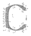
FIG. 1 is a schematic cross-section view of an example tire for use with the present invention. -
FIG. 2 is a schematic front elevation of the example tire ofFIG. 1 - "Axial" and "axially" means lines or directions that are parallel to the axis of rotation of the tire.
- "Circumferential" means lines or directions extending along the perimeter of the surface of the annular tread perpendicular to the axial direction.
- "Radially" and "radially" means directions radially toward or away from the axis of rotation of the tire.
-
FIGS. 1 and2 show anexample tire 10 for use with the present invention. Thetire 10 has atread 20 and acasing 12. Thecasing 12 has two sidewalls, one or moreradial plies 88 extending from, and wrapped about, twoannular beads 13, and abelt reinforcement structure 15 located radially between thetread 20 and the ply orplies 88. - The
plies 88 and thebelt reinforcement structure 15 may be cord reinforced elastomeric material. The cords may be, for example, steel wire filaments and the elastomer may be, for example, a vulcanized rubber material. In prior art tires, theannular beads 13 have steel wires wrapped into a bundle forming an inextensible bead core. Aninnerliner component 19, for example a halobutyl rubber, may form a somewhat air impervious chamber to contain the air pressure when thetire 10 is inflated. - The
tire 10 may further include anelastomeric apex 61 radially disposed above eachbead 13. Aturnup 21 of theply 88 in each bead area may be reinforced with aflipper 62, achipper 63, a gum andfabric chafer 64, agum strip 66, and/orelastomeric wedges 67. Additionally, thebelt reinforcement structure 15 may include a gum strip ofrubber material 72 and/or a plurality of elastomeric strips orwedges 74 in the lateral extremes or edges of thebelt reinforcement structure 15 in proximity of the lateral shoulders of thetread 20. Although not required to the practice of the inventive concept, these features are disclosed as features employed by an example embodiment. - The
example tread 20 may have a predetermined non-skid depth and four circumferential grooves including twocenterline grooves 14 and twoshoulder grooves 16 that divide thetread 20 into fivecircumferential ribs 18. Theshoulder grooves 16 may have a greater width than thecenterline grooves 14 thereby mitigating groove cracking. Thenarrower centerline grooves 14 may optimize rolling resistance and pressure distribution throughout thetread 20. Laterally extendingblind sipes 100 may extend at least partially across the fiveribs 18 of thetread 20 to form five circumferentially extendingribs 18 including twoshoulder ribs 24, tworiding ribs 26, and acenter rib 28. Further, one end of theblind sipes 100 may be enclosed within the edges of theribs 18 for optimizing wetskid performance. - In accordance with the present invention, the
beads 13 and/orapexes 61 comprise a fiber composite material constructed of resin-impregnated fiber or fabric layers. Accordingly, thebeads 13 and/orapexes 61 comprise a resin, a hardener, an accelerator, and fibers of glass and/or carbon. For example, theuncured beads 13 and/orapexes 61 may form a first liquid component mixture having for a weight of 0.1 kg resin 0.012 kg to 0.018 kg hardener and 0.003 kg to 0.007 kg accelerator, or equivalent ratio. Eachbead 13 andapex 61 may also be a single piece constructed in accordance with the present invention. - Further details about a usable first liquid component mixture and a respective fiber composite material are described in
DE 10 2005 054 334 A1paragraphs - The materials described in that document may be used as resin, hardener, accelerator and glass fibers in the embodiments here.
- The
beads 13 and/orapexes 61 accordingly are similar in composition to so called "Prepregs" used as springs and may be manufactured in the same way as such Prepregs. For further details, see paragraph 4 inDE 10 2005 054 334 A1 - A method of manufacturing such Prepregs which may be used to manufacture the
beads 13 and/orapexes 61 in accordance with the invention is also described inDE 10 2006 052 137 A1 . - Even though conventional steel beads are comparatively inexpensive to manufacture and reliable in operation, any innovation that can lighten a tire without detracting from performance in any other way is desirable for improving at least rolling resistance. Such
fiber composite beads 13 and/orapexes 61 may be produced from resin-impregnated fiber layers. - These resin-impregnated fiber layers may be manufactured in the desired shape and/or cut and placed one above the other into a mold that corresponds to the dimensions of the
beads 13 and/or apexes 61.Unfinished beads 13 and/orapexes 61 may be placed in the mold under the action of pressure and heat cured. - The resin-impregnated fibers and resin-impregnated fiber layers may be variously sized and oriented. For example, the fibers may be oriented radially away from, axially along, or circumferentially relative to the axis of rotation of the
beads 13. All or a portion of the fibers may be cylindrical, rectangular, triangular, etc. Fibers may be 10.0 mm in length up to the entire circumference of thebeads 13. Cross-sectional areas of the fibers may also be constant or vary. The relationship between the fibers and resin may be such that thebeads 13 and/apexes 61 may withstand extreme stresses occurring during the tire's operation and maximum service life. - The bead construction in accordance with this invention allows the manufacture of lighter tire compared to steel bead at equal strength. It also allows to reduce the bead size at equal strength. The bead construction in accordance with this invention also gives the tire designer a new degree of freedom in tire design. Finally, the bead construction in accordance with this invention may improve rolling resistance of the tire.
Claims (15)
- A tire comprising a tread (20) extending circumferentially around an outer portion of the pneumatic tire, two sidewalls extending radially inward from the tread, a carcass ply (88) extending radially inward through each sidewall, and two annular bead portions (13) comprising a composite material comprising resin-impregnated fabric or fiber layers.
- The tire of claim 1 wherein the composite material comprises or is constructed of the resin-impregnated fabric or fiber layers, the layers including a resin, a hardener, an accelerator, and fibers.
- The tire of claim 1 or 2, wherein the two annular bead portions (13) secure radially inner portions of the carcass ply (88).
- The tire of at least one of the previous claims, further comprising two apexes (61) respectively extending radially outward from each bead portion (13).
- The tire of at least one of the previous claims, wherein the fibers are or comprise glass fibers or carbon fibers.
- The tire of at least one of the previous claims, wherein the fibers comprise both glass fibers and carbon fibers.
- The tire of at least one of the previous claims, wherein the apexes (61) comprise a composite material constructed of resin-impregnated fabric layers.
- The tire of claim 7 wherein the apexes (61) comprise a composite material comprising or constructed of resin-impregnated fabric or fiber layers.
- The tire of claim 8 wherein the resin-impregnated fabric or fiber layers include a resin, a hardener, an accelerator, and fibers such as glass and/or carbon fibers.
- The tire of at least one of the previous claims, wherein each bead portion (13) comprises an integral structure with an associated apex (61).
- The tire of at least one of the previous claims, wherein the fibers have circular, rectangular or triangular cross-sections.
- The tire of at least one of the previous claims, wherein the fibers are oriented radially, axially or circumferentially.
- The tire of at least one of the previous claims, wherein the tire is a pneumatic tire.
- A method of making a tire in accordance with at least one of the previous claims, the method comprising:preparing a liquid component mixture comprising a resin, a hardener, an accelerator and fibers;forming uncured bead portions and/or uncured apexes or an uncured integral structure using said liquid component.
- The method of claim 14 wherein the resin-impregnated fabric or fiber layers are manufactured into a final shape of the bead portions (13) and/or wherein the resin-impregnated fabric or fiber layers are cut and placed one above the other into a mold that corresponds to the dimensions of the bead portions (13).
Applications Claiming Priority (1)
| Application Number | Priority Date | Filing Date | Title |
|---|---|---|---|
| US13/429,520 US20130248076A1 (en) | 2012-03-26 | 2012-03-26 | Bead structure for a pneumatic tire |
Publications (2)
| Publication Number | Publication Date |
|---|---|
| EP2644410A2 true EP2644410A2 (en) | 2013-10-02 |
| EP2644410A3 EP2644410A3 (en) | 2015-01-28 |
Family
ID=48013781
Family Applications (1)
| Application Number | Title | Priority Date | Filing Date |
|---|---|---|---|
| EP13160882.0A Withdrawn EP2644410A3 (en) | 2012-03-26 | 2013-03-25 | A bead structure for a tire |
Country Status (3)
| Country | Link |
|---|---|
| US (1) | US20130248076A1 (en) |
| EP (1) | EP2644410A3 (en) |
| KR (1) | KR20130109054A (en) |
Cited By (3)
| Publication number | Priority date | Publication date | Assignee | Title |
|---|---|---|---|---|
| WO2017123167A1 (en) * | 2016-01-12 | 2017-07-20 | Kordsa Teknik Tekstil Anonim Sirketi | Carbon fiber hybrid cord as bead wire |
| EP3450219A1 (en) * | 2017-08-29 | 2019-03-06 | The Goodyear Tire & Rubber Company | Bead structure for a pneumatic tire |
| CN110014789A (en) * | 2017-12-15 | 2019-07-16 | 固特异轮胎和橡胶公司 | Pneumatic tire with solid bead area structure |
Families Citing this family (3)
| Publication number | Priority date | Publication date | Assignee | Title |
|---|---|---|---|---|
| JP6369588B1 (en) * | 2017-03-27 | 2018-08-08 | 横浜ゴム株式会社 | Pneumatic tire |
| JP6922443B2 (en) * | 2017-06-05 | 2021-08-18 | 住友ゴム工業株式会社 | Pneumatic tires with external apex |
| JP6915524B2 (en) * | 2017-12-19 | 2021-08-04 | 住友ゴム工業株式会社 | Motorcycle tires for rough terrain |
Citations (4)
| Publication number | Priority date | Publication date | Assignee | Title |
|---|---|---|---|---|
| US4823857A (en) * | 1988-03-16 | 1989-04-25 | The Goodyear Tire & Rubber Company | Tire beads |
| US5198050A (en) * | 1989-04-18 | 1993-03-30 | Pirelli Armstrong Tire Corporation | Composite combination bead and bead filler |
| DE102005054334A1 (en) * | 2005-11-11 | 2007-05-24 | Ifc Composite Gmbh | Leaf spring, consisting of a special fiber composite material |
| DE102006052137A1 (en) * | 2006-11-06 | 2008-05-08 | Ifc Composite Gmbh | Process for producing leaf springs from a fiber composite material |
-
2012
- 2012-03-26 US US13/429,520 patent/US20130248076A1/en not_active Abandoned
-
2013
- 2013-03-25 KR KR1020130031305A patent/KR20130109054A/en not_active Application Discontinuation
- 2013-03-25 EP EP13160882.0A patent/EP2644410A3/en not_active Withdrawn
Patent Citations (4)
| Publication number | Priority date | Publication date | Assignee | Title |
|---|---|---|---|---|
| US4823857A (en) * | 1988-03-16 | 1989-04-25 | The Goodyear Tire & Rubber Company | Tire beads |
| US5198050A (en) * | 1989-04-18 | 1993-03-30 | Pirelli Armstrong Tire Corporation | Composite combination bead and bead filler |
| DE102005054334A1 (en) * | 2005-11-11 | 2007-05-24 | Ifc Composite Gmbh | Leaf spring, consisting of a special fiber composite material |
| DE102006052137A1 (en) * | 2006-11-06 | 2008-05-08 | Ifc Composite Gmbh | Process for producing leaf springs from a fiber composite material |
Cited By (4)
| Publication number | Priority date | Publication date | Assignee | Title |
|---|---|---|---|---|
| WO2017123167A1 (en) * | 2016-01-12 | 2017-07-20 | Kordsa Teknik Tekstil Anonim Sirketi | Carbon fiber hybrid cord as bead wire |
| RU2701619C1 (en) * | 2016-01-12 | 2019-09-30 | Кордса Текник Текстил Аноним Ширкети | Hybrid cord of carbon fibers as bead wire |
| EP3450219A1 (en) * | 2017-08-29 | 2019-03-06 | The Goodyear Tire & Rubber Company | Bead structure for a pneumatic tire |
| CN110014789A (en) * | 2017-12-15 | 2019-07-16 | 固特异轮胎和橡胶公司 | Pneumatic tire with solid bead area structure |
Also Published As
| Publication number | Publication date |
|---|---|
| US20130248076A1 (en) | 2013-09-26 |
| KR20130109054A (en) | 2013-10-07 |
| EP2644410A3 (en) | 2015-01-28 |
Similar Documents
| Publication | Publication Date | Title |
|---|---|---|
| EP2644410A2 (en) | A bead structure for a tire | |
| CN106994865B (en) | Pneumatic tire | |
| US20210197510A1 (en) | Method of forming a belt structure for a pneumatic tire | |
| CN110799356A (en) | Light tyre | |
| CN112976952A (en) | Truck tire | |
| RU2537058C2 (en) | Production of pneumatic tyre | |
| EP3501857B1 (en) | Pneumatic tire with a robust bead area structure | |
| EP2768682A1 (en) | All steel fabric radial construction for agricultural tires | |
| EP3031630B1 (en) | Aircraft tire | |
| EP3501856A1 (en) | Pneumatic tire with a robust ply ending structure | |
| JP6221788B2 (en) | Rehabilitation tire | |
| EP2326491B1 (en) | Process for building a green tyre for vehicle wheels and tyre built by said process | |
| EP3421262B1 (en) | Run flat tire and method for manufacturing same | |
| JP6457735B2 (en) | Pneumatic tire | |
| JP2013086667A (en) | Pneumatic tire | |
| JP2012076662A (en) | Pneumatic tire | |
| CN109195814B (en) | Tyre for vehicle wheels | |
| JP5054955B2 (en) | Aircraft radial tire | |
| JP6518136B2 (en) | Pneumatic tire | |
| EP2455237A1 (en) | Pneumatic tire carcass with non-continuous ply in the bead areas | |
| EP3176005A1 (en) | A bidirectional monobelt construction for a pneumatic tire | |
| CN112166028B (en) | Method for preparing a reinforcing layer for the manufacture of a reinforced tyre casing | |
| JP5084255B2 (en) | Manufacturing method of pneumatic radial tire | |
| JP7271907B2 (en) | Pneumatic tire and method for manufacturing pneumatic tire | |
| US20190152261A1 (en) | Commercial vehicle tyre |
Legal Events
| Date | Code | Title | Description |
|---|---|---|---|
| PUAI | Public reference made under article 153(3) epc to a published international application that has entered the european phase |
Free format text: ORIGINAL CODE: 0009012 |
|
| AK | Designated contracting states |
Kind code of ref document: A2 Designated state(s): AL AT BE BG CH CY CZ DE DK EE ES FI FR GB GR HR HU IE IS IT LI LT LU LV MC MK MT NL NO PL PT RO RS SE SI SK SM TR |
|
| AX | Request for extension of the european patent |
Extension state: BA ME |
|
| PUAL | Search report despatched |
Free format text: ORIGINAL CODE: 0009013 |
|
| AK | Designated contracting states |
Kind code of ref document: A3 Designated state(s): AL AT BE BG CH CY CZ DE DK EE ES FI FR GB GR HR HU IE IS IT LI LT LU LV MC MK MT NL NO PL PT RO RS SE SI SK SM TR |
|
| AX | Request for extension of the european patent |
Extension state: BA ME |
|
| RIC1 | Information provided on ipc code assigned before grant |
Ipc: B60C 15/04 20060101AFI20141219BHEP Ipc: B60C 15/06 20060101ALI20141219BHEP |
|
| STAA | Information on the status of an ep patent application or granted ep patent |
Free format text: STATUS: THE APPLICATION IS DEEMED TO BE WITHDRAWN |
|
| 18D | Application deemed to be withdrawn |
Effective date: 20150729 |