EP3397148B1 - Mobile cardiac monitoring device - Google Patents
Mobile cardiac monitoring device Download PDFInfo
- Publication number
- EP3397148B1 EP3397148B1 EP16882311.0A EP16882311A EP3397148B1 EP 3397148 B1 EP3397148 B1 EP 3397148B1 EP 16882311 A EP16882311 A EP 16882311A EP 3397148 B1 EP3397148 B1 EP 3397148B1
- Authority
- EP
- European Patent Office
- Prior art keywords
- ecg
- ceb
- leads
- lead
- ecg leads
- Prior art date
- Legal status (The legal status is an assumption and is not a legal conclusion. Google has not performed a legal analysis and makes no representation as to the accuracy of the status listed.)
- Active
Links
Images


Classifications
-
- A—HUMAN NECESSITIES
- A61—MEDICAL OR VETERINARY SCIENCE; HYGIENE
- A61B—DIAGNOSIS; SURGERY; IDENTIFICATION
- A61B5/00—Measuring for diagnostic purposes; Identification of persons
- A61B5/24—Detecting, measuring or recording bioelectric or biomagnetic signals of the body or parts thereof
- A61B5/316—Modalities, i.e. specific diagnostic methods
- A61B5/318—Heart-related electrical modalities, e.g. electrocardiography [ECG]
-
- A—HUMAN NECESSITIES
- A61—MEDICAL OR VETERINARY SCIENCE; HYGIENE
- A61B—DIAGNOSIS; SURGERY; IDENTIFICATION
- A61B5/00—Measuring for diagnostic purposes; Identification of persons
- A61B5/0002—Remote monitoring of patients using telemetry, e.g. transmission of vital signals via a communication network
- A61B5/0004—Remote monitoring of patients using telemetry, e.g. transmission of vital signals via a communication network characterised by the type of physiological signal transmitted
- A61B5/0006—ECG or EEG signals
-
- A—HUMAN NECESSITIES
- A61—MEDICAL OR VETERINARY SCIENCE; HYGIENE
- A61B—DIAGNOSIS; SURGERY; IDENTIFICATION
- A61B5/00—Measuring for diagnostic purposes; Identification of persons
- A61B5/0002—Remote monitoring of patients using telemetry, e.g. transmission of vital signals via a communication network
- A61B5/0015—Remote monitoring of patients using telemetry, e.g. transmission of vital signals via a communication network characterised by features of the telemetry system
- A61B5/0022—Monitoring a patient using a global network, e.g. telephone networks, internet
-
- A—HUMAN NECESSITIES
- A61—MEDICAL OR VETERINARY SCIENCE; HYGIENE
- A61B—DIAGNOSIS; SURGERY; IDENTIFICATION
- A61B5/00—Measuring for diagnostic purposes; Identification of persons
- A61B5/02—Detecting, measuring or recording for evaluating the cardiovascular system, e.g. pulse, heart rate, blood pressure or blood flow
- A61B5/024—Measuring pulse rate or heart rate
-
- A—HUMAN NECESSITIES
- A61—MEDICAL OR VETERINARY SCIENCE; HYGIENE
- A61B—DIAGNOSIS; SURGERY; IDENTIFICATION
- A61B5/00—Measuring for diagnostic purposes; Identification of persons
- A61B5/24—Detecting, measuring or recording bioelectric or biomagnetic signals of the body or parts thereof
- A61B5/25—Bioelectric electrodes therefor
- A61B5/279—Bioelectric electrodes therefor specially adapted for particular uses
- A61B5/28—Bioelectric electrodes therefor specially adapted for particular uses for electrocardiography [ECG]
-
- A—HUMAN NECESSITIES
- A61—MEDICAL OR VETERINARY SCIENCE; HYGIENE
- A61B—DIAGNOSIS; SURGERY; IDENTIFICATION
- A61B5/00—Measuring for diagnostic purposes; Identification of persons
- A61B5/24—Detecting, measuring or recording bioelectric or biomagnetic signals of the body or parts thereof
- A61B5/316—Modalities, i.e. specific diagnostic methods
- A61B5/318—Heart-related electrical modalities, e.g. electrocardiography [ECG]
- A61B5/327—Generation of artificial ECG signals based on measured signals, e.g. to compensate for missing leads
-
- A—HUMAN NECESSITIES
- A61—MEDICAL OR VETERINARY SCIENCE; HYGIENE
- A61B—DIAGNOSIS; SURGERY; IDENTIFICATION
- A61B5/00—Measuring for diagnostic purposes; Identification of persons
- A61B5/24—Detecting, measuring or recording bioelectric or biomagnetic signals of the body or parts thereof
- A61B5/316—Modalities, i.e. specific diagnostic methods
- A61B5/318—Heart-related electrical modalities, e.g. electrocardiography [ECG]
- A61B5/332—Portable devices specially adapted therefor
-
- A—HUMAN NECESSITIES
- A61—MEDICAL OR VETERINARY SCIENCE; HYGIENE
- A61B—DIAGNOSIS; SURGERY; IDENTIFICATION
- A61B5/00—Measuring for diagnostic purposes; Identification of persons
- A61B5/24—Detecting, measuring or recording bioelectric or biomagnetic signals of the body or parts thereof
- A61B5/316—Modalities, i.e. specific diagnostic methods
- A61B5/318—Heart-related electrical modalities, e.g. electrocardiography [ECG]
- A61B5/346—Analysis of electrocardiograms
- A61B5/349—Detecting specific parameters of the electrocardiograph cycle
- A61B5/355—Detecting T-waves
-
- A—HUMAN NECESSITIES
- A61—MEDICAL OR VETERINARY SCIENCE; HYGIENE
- A61B—DIAGNOSIS; SURGERY; IDENTIFICATION
- A61B5/00—Measuring for diagnostic purposes; Identification of persons
- A61B5/24—Detecting, measuring or recording bioelectric or biomagnetic signals of the body or parts thereof
- A61B5/316—Modalities, i.e. specific diagnostic methods
- A61B5/318—Heart-related electrical modalities, e.g. electrocardiography [ECG]
- A61B5/346—Analysis of electrocardiograms
- A61B5/349—Detecting specific parameters of the electrocardiograph cycle
- A61B5/358—Detecting ST segments
-
- A—HUMAN NECESSITIES
- A61—MEDICAL OR VETERINARY SCIENCE; HYGIENE
- A61B—DIAGNOSIS; SURGERY; IDENTIFICATION
- A61B5/00—Measuring for diagnostic purposes; Identification of persons
- A61B5/24—Detecting, measuring or recording bioelectric or biomagnetic signals of the body or parts thereof
- A61B5/316—Modalities, i.e. specific diagnostic methods
- A61B5/318—Heart-related electrical modalities, e.g. electrocardiography [ECG]
- A61B5/346—Analysis of electrocardiograms
- A61B5/349—Detecting specific parameters of the electrocardiograph cycle
- A61B5/363—Detecting tachycardia or bradycardia
-
- A—HUMAN NECESSITIES
- A61—MEDICAL OR VETERINARY SCIENCE; HYGIENE
- A61B—DIAGNOSIS; SURGERY; IDENTIFICATION
- A61B5/00—Measuring for diagnostic purposes; Identification of persons
- A61B5/24—Detecting, measuring or recording bioelectric or biomagnetic signals of the body or parts thereof
- A61B5/316—Modalities, i.e. specific diagnostic methods
- A61B5/318—Heart-related electrical modalities, e.g. electrocardiography [ECG]
- A61B5/346—Analysis of electrocardiograms
- A61B5/349—Detecting specific parameters of the electrocardiograph cycle
- A61B5/366—Detecting abnormal QRS complex, e.g. widening
-
- A—HUMAN NECESSITIES
- A61—MEDICAL OR VETERINARY SCIENCE; HYGIENE
- A61B—DIAGNOSIS; SURGERY; IDENTIFICATION
- A61B5/00—Measuring for diagnostic purposes; Identification of persons
- A61B5/72—Signal processing specially adapted for physiological signals or for diagnostic purposes
- A61B5/7235—Details of waveform analysis
- A61B5/7264—Classification of physiological signals or data, e.g. using neural networks, statistical classifiers, expert systems or fuzzy systems
- A61B5/7267—Classification of physiological signals or data, e.g. using neural networks, statistical classifiers, expert systems or fuzzy systems involving training the classification device
-
- A—HUMAN NECESSITIES
- A61—MEDICAL OR VETERINARY SCIENCE; HYGIENE
- A61B—DIAGNOSIS; SURGERY; IDENTIFICATION
- A61B5/00—Measuring for diagnostic purposes; Identification of persons
- A61B5/74—Details of notification to user or communication with user or patient; User input means
- A61B5/742—Details of notification to user or communication with user or patient; User input means using visual displays
-
- A—HUMAN NECESSITIES
- A61—MEDICAL OR VETERINARY SCIENCE; HYGIENE
- A61B—DIAGNOSIS; SURGERY; IDENTIFICATION
- A61B5/00—Measuring for diagnostic purposes; Identification of persons
- A61B5/74—Details of notification to user or communication with user or patient; User input means
- A61B5/746—Alarms related to a physiological condition, e.g. details of setting alarm thresholds or avoiding false alarms
Definitions
- a standard surface ECG is recorded showing 12 different lead 'directions' from eight independent leads, though only 10 recording electrodes on the skin are required to achieve this. Six of these electrodes are placed on the chest overlying the heart to record the six chest or precordial leads. Four electrodes are placed on the limbs to record the six limb leads. In a standard ECG, it is essential that each of the 10 recording electrodes is placed in its correct position, otherwise the appearance of the ECG will be changed significantly, preventing correct interpretation.
- the ECG is the first test in the initial evaluation of chest pain patients, but multiple studies have demonstrated that the ECG has low sensitivity in initially diagnosing AMI.
- Rapid diagnosis of acute myocardial ischemic injury is the key to implementing immediate treatment.
- ACS presumed acute coronary syndrome
- the ECG and cardiac serum markers are typically acquired at the time of patient arrival and every several hours thereafter, for up to 24 hours of patient observation to identify the developments of an ACS.
- the patient may be at risk during the time between these serum markers and ECG acquisitions, especially if the patient has silent ischemic injuries.
- approximately 95% of patients who visit emergency rooms with chest pains are sent home without treatment. These patients may also be at risk.
- a mobile cardiac monitoring device comprises electrocardiogram (ECG) electrodes for acquiring voltage-time measurements for a subset of ECG leads of a user, an ECG derivation module for deriving a full set of ECG leads for the user from the subset of ECG leads, a heart rate calculation and cardiac rhythm monitoring module for calculating a heart rate and monitoring cardiac rhythm of the user based on at least one of the measured subset of ECG leads, and a cardiac electrical biomarker (CEB) calculation module for calculating a CEB from the derived full set of ECG leads.
- ECG electrocardiogram
- FIG. 1 illustrates a mobile cardiac monitoring device 100 according to an embodiment of the described invention.
- the mobile cardiac monitoring device 100 can be implemented as a stand-alone device or can be implemented as part of another mobile device, such as a cellular phone, tablet, etc.
- the cardiac monitoring device 100 is a portable, hand-held device, and thus can be considered a "mobile" or “ambulatory” device.
- the mobile cardiac monitoring device 100 includes a processor 102 operatively coupled to a data storage device 106 and a memory 104.
- the processor 102 controls the overall operation of cardiac monitoring device 100 by executing computer program instructions that define such operations.
- the processor 102 may include both general and special purpose microprocessors, and may be the sole processor or one of multiple processors of the cardiac monitoring device 100.
- the processor 102 may include one or more central processing units (CPUs), for example.
- the processor may also include one or more graphics processing units (GPUs).
- the processor 102, data storage device 106, and/or memory 104 may include, be supplemented by, or incorporated in, one or more application-specific integrated circuits (ASICs) and/or one or more field programmable gate arrays (FPGAs).
- ASICs application-specific integrated circuits
- FPGAs field programmable gate arrays
- the data storage device 106 and memory 104 each include a tangible non-transitory computer readable storage medium.
- the memory 104 may include high-speed random access memory, such as dynamic random access memory (DRAM), static random access memory (SRAM), double data rate synchronous dynamic random access memory (DDR RAM), or other random access solid state memory devices.
- DRAM dynamic random access memory
- SRAM static random access memory
- DDR RAM double data rate synchronous dynamic random access memory
- the data storage device 106 may include non-volatile memory, such as one or more magnetic disk storage devices such as internal hard disks and removable disks, magneto-optical disk storage devices, optical disk storage devices, flash memory devices, semiconductor memory devices, such as erasable programmable read-only memory (EPROM), electrically erasable programmable read-only memory (EEPROM), compact disc read-only memory (CD-ROM), digital versatile disc read-only memory (DVD-ROM) disks, or other non-volatile solid state storage devices.
- the cardiac monitoring device 100 also includes removable storage 118.
- the removable storage 118 includes a port and corresponding removable storage medium.
- the removable storage 118 can be a Secure Digital (SD) port and corresponding SD card, but the described invention is not limited thereto, and any other type of removable storage can be used as well.
- SD Secure Digital
- the cardiac monitoring device 100 may also include one or more network interfaces 124 for communicating with other devices via one or more networks.
- the network interfaces 124 can include a cellular network interface for communicating over a cellular network, such as Global System for Mobile Communications (GSM) network, Code Division Multiple Access (CDMA) network, or Long Term Evolution (LTE) network.
- GSM Global System for Mobile Communications
- CDMA Code Division Multiple Access
- LTE Long Term Evolution
- a cellular network may be a 3G or 4G network, over which data can be transmitted.
- the network interfaces 124 can also include a short message service (SMS) and/or multi-media message service (MMS) network interface for transmitting and receiving text messages and/or multi-media messages.
- SMS short message service
- MMS multi-media message service
- the network interfaces 124 may also include a wireless network interface controller (WNIC) for wireless communications over a data network, such as a WIFI network.
- WNIC wireless network interface controller
- the network interfaces 124
- the mobile cardiac monitoring device 100 is communicatively coupled to ECG electrodes 128.
- the ECG electrodes can be connected to the cardiac monitoring device 100 via a cable.
- the ECG electrodes 128 can be connected to a USB cable that is inserted into a USB port of the mobile. It is to be understood that the described invention is not limited to a USB cable and other types of cables may be used as well.
- the ECG electrodes 128 may communicate with the mobile cardiac monitoring device 100 wirelessly.
- the ECG electrodes 128 may communicate with the mobile cardiac monitoring device 100 via a Bluetooth connection.
- the ECG electrodes 128 are placed on the body of a user or patient and transmit voltage-time measurements for a subset of ECG leads to the mobile cardiac monitoring device 100.
- ECG leads I, II, and V2 are measured by the ECG electrodes 128.
- ECG leads I, aVF, and V2 can be measured by the ECG electrodes 128.
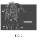
- the ECG electrodes 128 can include five electrodes to measure the three ECG leads, where one of the electrodes is a ground. In a possible embodiment, the ground can be included in one of the other electrodes and fewer total electrodes can be used.
- Electrode 208 is a ground and is typically placed on the right leg, making its placement easy for a user, but the location of the ground electrode is not limited to the right leg and can be placed in other locations as well. Electrode 210 also corresponds to an anatomical location that is easy for a user to locate. The signal from the electrodes may be improved if the electrodes are not placed directly on a muscle, which can cause interference. In an exemplary alternative implementation, a ground can be included in the V2 electrode (210). In this case, electrode 208 is not needed and four electrodes can be used instead. In other possible implementations, the ground can be in one of the other electrodes as well. Using the electrode placements of FIG.
- ECG leads I, II, and V2 are members of the set of leads that makes up the standard 12-lead ECG.
- V9 placement of V9 in the posterior chest (behind V2) can be in place of V2 in the above described example to derive the n-lead ECG and construct the CEB.
- the ECG derivation module 108, heart rate and cardiac rhythm module 110, dynamic CEB calculation module 112, and alert module 114 can be stored in the data storage device 106.
- Each of these modules includes computer program instructions for performing a particular set of operations when loaded into the memory 104 and executed by the processor 102.
- the data storage device 106 also includes patient data storage 116 for storing various patient data, including voltage-time measurements received from the ECG electrodes 128, derived ECG data generated by the ECG derivation module 108, heart rate and cardiac rhythm data generated by the heart rate and cardiac rhythm module 110, and cardiac electrical biomarker (CEB) data generated by the dynamic CEB calculation module 112.
- CEB cardiac electrical biomarker
- a standard ECG is measured by placing a series of electrodes on the patient's skin.
- the standard ECG record includes 12 lead waveforms, denoted as I, II, III, aVR, aVL, aVF, V1, V2, V3, V4, V5, and V6, arranged in a specific order that is interpreted by a physician using pattern recognition techniques.
- 10 electrodes are placed on the body torso to measure the electrical potentials that define the standard 12 leads.
- the ECG derivation module 108 can derive a full set of ECG leads from the subset of ECG leads measured by the ECG electrodes 128.
- the ECG derivation module 108 can derive a complete n-lead (e.g., 12-lead) ECG for a patient from the 3 measured leads received from the ECG electrodes 128.
- the ECG derivation module 108 can derive the complete n-lead ECG from the 3 measured leads by applying a stored universal transformation matrix that is generated from sets of training ECG data using abstract factor analysis and a simplex optimization algorithm.
- a method for deriving an n-lead ECG is described in greater detail in United States Patent No. 6,901,285 .
- the aVF ECG lead is calculated from the measured ECG leads I and II.
- the aVF (augmented vector foot) lead can be calculated from the known geometry of leads I and II.
- the aVF lead has a positive pole on the left leg and the negative pole is a combination of the right arm electrode and the left arm electrode.
- the method of FIG. 3 acquires the voltage-time measurements for leads I, II, and V2, and then calculates lead aVF from leads I and II
- voltage time measurements for leads I, aVF, and V2 can be acquired directly from the ECG electrodes.
- an n-lead ECG is derived from leads I, aVF, and V2 using a universal transformation matrix.
- the universal transformation matrix is derived from training sets of ECG data and stored as part of the ECG derivation module 108 in the data storage device 106.
- lead sets that can be derived from the 3 leads (I, aVF, and V2) are:
- the universal transformation matrix is particular to the number of leads in the n-lead ECG being derived.
- the universal transformation matrix is generated from a training set of ECG voltage-time data arrays.
- an abstract factor analysis (“AFA”) technique can be applied to each ECG voltage-time array in the training set in order to minimize the error in the measured arrays.
- a simplex optimization technique (“SOP”) is then applied to the training set in order to derive the universal transformation matrix that is applicable to all patients and is time independent.
- the universal transformation matric can also be independent to other characteristics such as gender, body type, etc.
- the universal transformation matrix is an Nx3 matrix that is applied to the subset of 3 leads to generate the full n-lead ECG.
- the Nx3 universal transformation matrix is multiplied by a vector comprising 3 leads ⁇ I, aVF, V2 ⁇ for a particular time to yield a full n-lead ECG. It with be understood by those knowledgeable in the art that ⁇ I, aVF, V2 ⁇ proximates a basis orthogonal lead set that is necessary to construct the universal transformation matrix.
- basis orthogonal lead sets may be used to perform this step, as will be recognized by those knowledgeable in the art.
- exemplary basis orthogonal lead sets include ⁇ I, aVF, V9 ⁇ , ⁇ V6R, aVF, V2 ⁇ , and ⁇ V6R, aVF, V9 ⁇ , but the present invention is not limited thereto.
- the heart rate and cardiac rhythm module 110 identifies the cardiac rhythm and calculates a heart rate of the user from at least one of the measured ECG leads.
- ECG is typically presented as a graph plotting electrical activity of the heart on the vertical axis against time on the horizontal axis.
- Standard ECG paper moves at 25 mm per second during real-time recording. This means that when looking at a printed ECG a distance of 25 mm along the horizontal axis represents 1 second.
- ECG paper is marked with a grid of small and large squares. Each small square represents 40 milliseconds (ms) in time along the horizontal axis and each larger square contains 5 small squares, thus representing 200 ms. Standard paper speeds and square markings allow easy measurement of cardiac timing intervals.
- the amplitude or voltage of the recorded electrical signal is expressed in the vertical dimension and is measured in millivolts (mV).
- mV millivolts
- 1 mV is represented by a deflection of 10 mm.
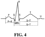
- FIG. 4 illustrates a typical cardiac electrical signal as measured by an ECG. Since the first structure to be depolarized during normal sinus rhythm is the right atrium, closely followed by the left atrium, the first electrical signal on a normal ECG originates from the atria and is known as the P wave. Although there is usually only one P wave in most leads of an ECG, the P wave is in fact the sum of the electrical signals from the two atria, which are usually superimposed. There is a short, physiological delay as the atrioventricular (AV) node slows the electrical depolarization before it proceeds to the ventricles that is responsible for the PR interval, a short period where no electrical activity is seen on the ECG, represented by a straight horizontal or "isoelectric" line.
- AV atrioventricular
- a PR interval is measured from the beginning of the P wave to the first deflection of the QRS complex and has a normal range of 120 - 200 ms (3 - 5 small squares on ECG paper).
- the QRS duration is measured from the first deflection of the QRS complex to the end of the QRS complex at the isoelectric line and has a normal range of up to 120 ms (3 small squares on ECG paper).
- the QT interval is measured from the first deflection of the QRS complex to the end of the T wave at the isoelectric line and has a normal range of up to 440 ms, although this varies with heart rate and may be slightly longer in females.
- the heart rate and cardiac rhythm module 110 can calculate the heart rate of the patient by determining an amount of time between each QRS complex in one or multiple ECG leads. Each second of time in the ECG signal can be estimated by 25 mm (5 large squares) along the horizontal axis. Accordingly, the number of large squares between each QRS complex of the ECG lead provides an approximate amount of time between each QRS complex, which can be used to estimate the heart rate. For example, if the number of large squares between each QRS complex is 5, the heart rate is 60 beats per minute; if the number of large squares between each QRS complex is 3, the heart rate is 100 beats per minute; if the number of large squares between each QRS complex is 2, the heart rate is 150 beats per minute.
- the standard paper rate and square markings can be scaled for display of the ECG signals on the display 120, and the heart rate can be similarly estimated.
- the heart rate and cardiac rhythm module 110 can also evaluate the acquired and/or derived ECG signals to monitor the cardiac rhythm to help identify whether the cardiac rhythm is regular or irregular.
- the dynamic CEB calculation module 112 calculates a CEB from the derived ECG.
- the CEB is an electrical biomarker that quantifies dipolar energy content in the cardiac electrical field. The more dipolar energy content that is present in the cardiac electrical field, the more normal is the patient's condition, while the more multipolar energy content that is present in the cardiac electrical field, the more abnormal is the patients' condition.
- the CEB can be used as a "point-of-care" diagnostic test to detect the presence or absence of acute myocardial ischemic injury (AMII) including acute myocardial infarction (AMI).
- AMII acute myocardial ischemic injury
- the CEB can also be used to monitor a patient who is not initially diagnosed with AMII/AMI to monitor and detect the onset and/or development of AMII/AMI in real time.
- the electrical field of the heart starts at a cellular level and there is a very small multi-polar component to the electrical field in cases of AMII/AMI.
- the CEB can be calculated from the derived ECG by calculating the third eigenvalue of the derived ECG voltage-time data.
- abstract factor analysis AFA
- AFA abstract factor analysis
- D represent the data matrix array of the derived ECG voltage-time data.
- the third eigenvalue ( ⁇ 3 ) as calculated is used as the CEB.
- the present inventor has determined that the third eigenvalue, which provides a measurement of dipolar activity of the cardiac electrical field, can be used as a GEB that is indicative of acute myocardial ischemic injury.
- the more multipolar (less dipole) forces in the cardiac electrical field the greater the potential for an AMII/AMI.
- the CEB has a numerical value that quantifies the multipolar forces in the cardiac electrical field suggestive of an AMI. For example, a CEB value less than 66 can be indicative of a normal condition, a CEB value between 66 and 94 can be considered to be in an indeterminate zone, and a CEB value greater than 94 can be indicative of an abnormal condition. It is to be understood that the present invention is not limited to these particular cutoff values, and the cutoff values may vary based on user operability and variation of a more specific universal transformation matrix.
- the dynamic CEB calculation module 112 calculates a dynamic CEB by calculating a respective CEB value from the derived EGG for each heartbeat.
- the abstract factor analysis is applied to the derived EGG voltage-time data for each heartbeat to calculate the third eigenvalue of the derived EGG voltage-time data for each heart, resulting in a respective CEB value for each heartbeat.
- the dynamic CEB data can be displayed by the display 120 as a graph of CEB over time.
- a number of heart beats in the derived EGG in a predetermined time interval e.g. 10 seconds
- a static CEB is calculated for that time interval based on the median beat EGG data.
- beats of the same shape are combined into an accurate representative cycle. Noise is dramatically reduced by this process. Successive CEB's in a predetermined interval of time can lead to the display of a dynamic CEB in this instance.
- a fractal CEB may be calculated instead of or in addition to the eigenvalue CEB.
- the fractal CEB can be calculated using the method described in United States Patent No. 6,920,349 .
- a spatial curve can be defined from the lead values for at least three leads of the derived EGG.
- a fractal index for the spatial curve is calculated as a function of time.
- the time rate of change of the fractal index can be calculated as the CEB.
- a negative time rate of change is indicative of normal cardiac activity, while a positive time rate of change is indicative of pathological activity.
- the dynamic CEB calculation module 112 may calculate both the eigenvalue CEB and the fractal CEB for each heart beat and the alert module 114 may utilize a combination of the eigenvalue CEB and the fractal CEB in determining whether an alert condition has been triggered.
- Other fractal analyses of the spatial curves can be constructed as well.
- a suite of multiple CEBs can be calculated and displayed and/or transmitted to a device associated with a physician to assist the physician in understanding the onset and/or development of AMII/AMI.
- the alert module 114 monitors the CEB values calculated by the dynamic CEB calculation module 112 and controls the mobile cardiac monitoring device 100 to send an alert when a certain trigger condition is detected.
- the alert module 114 monitors dynamic CEB values calculated for each heart beat and determine whether the CEB value for each heart beat is in an abnormal zone. For example, for the eigenvalue CEB, a CEB value greater than 94 can be considered to be in the abnormal zone. If a programmable percentage of the heart beats in the abnormal zone within a predetermined time interval is greater than a threshold, the alert module 114 determines that the trigger condition has been detected and transmits an alert message via the network interface(s) 124.
- the alert message can be a text message sent to a predetermined remote device, such as device associated with a physician of the patient.
- the text message can include the derived ECG data and/or the measured ECG leads, the estimated heart rate data, and the CEB data for a certain time period preceding the detection of the trigger condition.
- the alert message may be an emailmessage sent to a predetermined email address, and the email message may include the derived ECG data and/or the measured ECG leads, the heart rate data, and the CEB data of the patient.
- the alert module 114 may also control the mobile cardiac monitoring device 100 to place a telephone call to a telephone number associated with a predetermined remote device (e.g. the telephone of the physician), and play a predetermined voice alert message.
- the alert module 114 may also control the mobile cardiac monitoring device 100 to automatically contact and emergency response system.
- the alert module may control the mobile cardiac monitoring device 100 to automatically call 911 in response to the detection of a trigger condition.
- the data can be downloaded to a reader device, such as a Vetraplex ECG System, that is capable of performing additional calculations and displaying additional information.
- a reader device such as a Vetraplex ECG System
- such a device may derive a 15 or 22 lead ECG from the measured ECG leads, display the derived 15 or 22 lead ECG.
- FIG. 5 illustrates a method of cardiac monitoring using a mobile cardiac monitoring device according to an embodiment of the described invention.
- the method of FIG. 5 may be performed by the mobile cardiac monitoring device 100 of FIG. 1 .
- the method steps of FIG. 5 can be repeated to provide real-time cardiac monitoring for a patient.
- a mobile cardiac monitoring device 100 can be provided to a patient who is not under direct supervision of a doctor, such as a patient who exhibited chest pain but was sent home from an emergency room, and the method of FIG. 5 can be performed to provide real-time remote cardiac monitoring of the patient.
- the method of FIG. 5 can be performed for real-time point of care of a patient in a hospital, doctor's office, etc.
- digitized voltage-time measurements are received for 3 ECG leads. For example, voltage time measurements for leads I, II, and V2 or for leads I, aVF, and V2 can be received from the ECG electrodes 128.
- a full 12-lead ECG is derived from the voltage-time measurements for the 3 ECG leads.
- the ECG derivation module can derive the 12-lead ECG using a pre-stored universal transformation matrix. Although the method of FIG. 5 derives a 12-lead ECG, the described invention is not limited thereto, and any other n-lead ECG can be similarly derived.
- the mobile cardiac monitoring device may derive a full 15-lead or 22-lead ECG.
- the heart rate of the patient is calculated from the received voltage time measurements for at least one of the ECG leads and the cardiac rhythm is monitored.
- a dynamic CEB is calculated from the derived 12-lead ECG.
- the dynamic CEB can be constructed by calculating a CEB value for each heartbeat.
- the CEB value for each heart beat can be constructed by calculating the third eigenvalue of the derived 12-lead ECG voltage-time data corresponding to each heartbeat. It is also possible that other eigenvalue analyses can be performed as well.
- the mobile cardiac monitoring device 100 may perform any one of these steps, all of these steps, or any combination of these steps.
- the derived ECG data, the heart rate data, the cardiac rhythm data, and the CEB data for the patient are stored.
- This patient data can be stored in the patient data storage 116 of the data storage device 106 and/or on the removable storage device 118.
- the mobile cardiac monitoring device 100 can be used to monitor a patient for a specific time period (e.g., 1 or 2 days) and the patient data acquired during that time period is stored on the removable storage device 118.
- a doctor can then remove the removable storage 118 and load the patient data from the removable storage to the doctor's computer (or other device) in order to view the patient data.
- the derived EGG data, the heart rate data, the cardiac rhythm data, and the CEB data of the patient may be displayed on the display 120 of the mobile cardiac monitoring device 100.
- the patient data can be displayed in real-time as the patient data is acquired and calculated.
- the derived EGG data can be displayed by displaying the EGG signals over time for each of the leads of the derived 12-lead EGG. It is also possible that the EGG data can be displayed by displaying a 3-dimensionalspatialEGG loop resulting from plotting the 3 measured leads (I, aVF, and V2) or any other 3 orthogonal leads of the derived 12-lead EGG against each other in 3-dimensional space.
- the mobile cardiac monitoring device can display the EGG vector loops from a full 15-lead and/or 22-lead EGG derived by the mobile cardiac monitoring device.
- the heart rate can be displayed as a numeric value that is updated as needed.
- Dynamic CEB data such as CEB values calculated for each heartbeat, can be displayed as a graph of CEB over time.
- the Dynamic CEB data can be displayed in real-time as it is calculated. It is also possible to display dynamic CEB data as a numeric value that is updated as it changes.
- the CEB data can be color coded, for example using different colors for CEB values corresponding to a normal zone, an indeterminate zone, and an abnormal zone.
- the derived EGG data, the heart rate data, the cardiac rhythm data, and the CEB data of the patient is transmitted to a remote device.
- the patient data can be transmitted to a computer or other device associated with a doctor or a remote monitoring system.
- the data can be transmitted to a reader device, which can calculate a 15 or 22 lead EGG of the patient.
- the full 15 and/or 22 lead EGG can be derived by the cardiac monitoring device and transferred to the remote device.
- the patient data can be transmitted in real-time as it is acquired and calculated. This allows a doctor to monitor the patient data in real-time even if the patient is located remotely.
- the patient data can be transmitted at programmable time intervals.
- the patient can manually trigger the mobile cardiac monitoring device 100 to transmit the data.
- the mobile cardiac monitoring device may be equipped with an event button that the patient/user can select to manually trigger the patient data to be transmitted.
- the patient data may be transmitted via any type of data network, such as a cellular network, WIFI, text or multimedia messaging, Bluetooth, etc., using the network interface(s) 124.
- the patient data can be transmitted to a monitoring service, which can then monitor the patient data to detect emergency conditions instead of or in addition to an alert module 114 in the mobile cardiac monitoring device 100.
- FIG. 6 illustrates a method of cardiac monitoring and alert notification using a mobile cardiac monitoring device according to an embodiment of the described invention.
- the method of FIG. 6 may be performed by the mobile cardiac monitoring device 100 of FIG. 1 .
- the method steps of FIG. 6 can be repeated to provide real-time cardiac monitoring for a patient.
- a mobile cardiac monitoring device 100 can be provided to a patient who is not under direct supervision of a doctor, such as a patient who exhibited chest pain but was sent home from an emergency room, and the method of FIG. 6 can be performed to provide real-time cardiac monitoring of the patient.
- the method of FIG. 6 can be performed for real-time point of care of a patient in a hospital, doctor's office, etc.
- digitized voltage-time measurements are received for 3 orthogonal ECG leads. For example, voltage time measurements for leads I, II, and V2 or for leads I, aVF, and V2 can be received from the ECG electrodes 128.
- a full 12-lead ECG is derived from the voltage-time measurements for the 3 ECG leads.
- the ECG derivation module can derive the 12-lead ECG using a pre-stored universal transformation matrix.
- the method of FIG. 5 derives a 12-lead ECG, the described invention is not limited thereto, and any other n-lead ECG can be similarly derived.
- the heart rate of the patient is calculated from the received voltage-time measurements for at least one of the ECG leads and the cardiac rhythm is monitored.
- a dynamic CEB is calculated from the derived 12-lead ECG.
- the dynamic CEB can be constructed by calculating a CEB value for each heartbeat.
- the CEB value for each heart beat can be constructed by calculating the eigenvalues of the derived 12-lead ECG voltage-time data corresponding to each heartbeat.
- a trigger condition it is determined if a trigger condition is detected.
- a trigger condition it is determined, for each heartbeat, whether a CEB associated with that heart beat is in an abnormalzone. For example, for eigenvalue CEB, a CEB value greater than 94 may be considered to be in an abnormal zone.
- a trigger condition can be detected when a programmable percentage of heart beats having a CEB value in the abnormal zone within a predetermined time interval is greater than a threshold.
- a trigger condition is detected when P > ⁇ , where P is the percentage of heart beats in a time interval t (e.g., 1 minute) that have a CEB value in the abnormalzone, and ⁇ is a threshold percentage value (e.g., 90%). It is also possible that the trigger condition can be detected based on an average CEB value over a certain time interval, based on a fractal CEB, or based on a combination of a fractal and an eigenvalue CEB or other combination of CEBs. If no trigger condition is detected, the method returns to step 602 and continues monitoring the patient by repeating steps 602, 604, 606, and 608. If a trigger condition is detected, the method proceeds to step 610.
- the reader device may also calculate a static CEB value based on the derived n-lead ECG and display the CEB value.
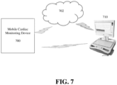
- the mobile cardiac monitoring device 700 can transmit the data to the reader device 710 (or to the cloud 702) at predetermined (programmable) time intervals. It is also possible that the mobile cardiac monitoring device 700 can transmit the data to the reader device 710 (or to the cloud 702) in response to detection of an alert condition at the mobile cardiac monitoring device or in response to a manual trigger (e.g., selection of event button) input by the patient at the mobile cardiac monitoring device 700. It is also possible that the mobile cardiac monitoring device 700 can transmit the data to the reader device 710 (or to the cloud 702) in response to a request for data being received at the mobile cardiac monitoring device 700.
- a manual trigger e.g., selection of event button
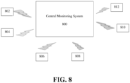
- FIG. 8 illustrates a system for cardiac monitoring of a patient according to an embodiment of the present invention.
- the system includes a central monitoring system 800 and a plurality of mobile cardiac monitoring devices 802, 804, 806, 808, 810, and 812.
- the mobile cardiac monitoring devices 802, 804, 806, 808, 810, and 812 can be implemented similarly to the mobile cardiac monitoring device 100 of FIG. 1 . It is also possible that the mobile cardiac monitoring devices 802, 802, 806, 808, 810, and 812 of FIG. 8 can be implemented without the alert module 114, or without any of the ECG derivation module 108, the cardiac rhythm estimation module 110, the dynamic CEB calculation module 112, and the alert module 114.
- the mobile cardiac monitoring devices 802, 804, 806, 808, 810, and 812 are each associated with a respective patient and transmit respective patient data to the central monitoring system 800.
- the central monitoring system 800 monitors the patient data for each of the patients associated with the mobile cardiac monitoring devices 802, 804, 806, 808, 810, and 812.
- the mobile cardiac monitoring devices 802, 804, 806, 808, 810, and 812 can transmit the patient data via any type of data network, such as WIFI, Bluetooth, etc.
- the system of FIG. 8 can be implemented in a hospital and each patient can be provided with one of mobile cardiac monitoring devices 802, 804, 806, 808, 810, and 812.
- the central monitoring system 800 can then be used to simultaneously monitor all of the patients, or all patients on a floor or section of the hospital.
- each of the mobile cardiac monitoring devices 802, 804, 806, 808, 810, and 812 can acquire 3-lead ECG voltage-time measurements, derive the full n-lead ECG, estimate the heart rate, and calculate the CEB for the respective patient, and then transmit the derived ECG, estimated heart rate, and calculated CEB for the respective to the central monitoring system 800 in real-time.
- the central monitoring system 800 then monitors the CEB of each patient to detect whether the trigger condition has occurred and generates the alert notification for a patient when the trigger condition is detected.
Landscapes
- Health & Medical Sciences (AREA)
- Life Sciences & Earth Sciences (AREA)
- Engineering & Computer Science (AREA)
- Cardiology (AREA)
- Physics & Mathematics (AREA)
- Animal Behavior & Ethology (AREA)
- Biomedical Technology (AREA)
- Heart & Thoracic Surgery (AREA)
- Medical Informatics (AREA)
- Molecular Biology (AREA)
- Surgery (AREA)
- Biophysics (AREA)
- General Health & Medical Sciences (AREA)
- Public Health (AREA)
- Veterinary Medicine (AREA)
- Pathology (AREA)
- Physiology (AREA)
- Computer Networks & Wireless Communication (AREA)
- Artificial Intelligence (AREA)
- Evolutionary Computation (AREA)
- Fuzzy Systems (AREA)
- Mathematical Physics (AREA)
- Computer Vision & Pattern Recognition (AREA)
- Psychiatry (AREA)
- Signal Processing (AREA)
- Measurement And Recording Of Electrical Phenomena And Electrical Characteristics Of The Living Body (AREA)
Applications Claiming Priority (2)
| Application Number | Priority Date | Filing Date | Title |
|---|---|---|---|
| US14/984,838 US10602946B2 (en) | 2015-12-30 | 2015-12-30 | Mobile cardiac monitoring device |
| PCT/US2016/066502 WO2017116703A1 (en) | 2015-12-30 | 2016-12-14 | Mobile cardiac monitoring device |
Publications (3)
| Publication Number | Publication Date |
|---|---|
| EP3397148A1 EP3397148A1 (en) | 2018-11-07 |
| EP3397148A4 EP3397148A4 (en) | 2019-05-22 |
| EP3397148B1 true EP3397148B1 (en) | 2024-07-10 |
Family
ID=59225515
Family Applications (1)
| Application Number | Title | Priority Date | Filing Date |
|---|---|---|---|
| EP16882311.0A Active EP3397148B1 (en) | 2015-12-30 | 2016-12-14 | Mobile cardiac monitoring device |
Country Status (8)
| Country | Link |
|---|---|
| US (1) | US10602946B2 (enExample) |
| EP (1) | EP3397148B1 (enExample) |
| JP (1) | JP7051707B2 (enExample) |
| CN (2) | CN108697357B (enExample) |
| AU (2) | AU2016380869B2 (enExample) |
| CA (1) | CA3008146C (enExample) |
| ES (1) | ES2983220T3 (enExample) |
| WO (1) | WO2017116703A1 (enExample) |
Families Citing this family (15)
| Publication number | Priority date | Publication date | Assignee | Title |
|---|---|---|---|---|
| CN107847171A (zh) | 2015-04-09 | 2018-03-27 | 哈特比姆公司 | 用于自动诊断的移动式三导联心脏监测设备和方法 |
| US11071490B1 (en) | 2015-04-09 | 2021-07-27 | Heartbeam, Inc. | Electrocardiogram patch devices and methods |
| DE102015213483A1 (de) * | 2015-07-17 | 2017-01-19 | Robert Bosch Gmbh | Verfahren und Vorrichtung zum Steuern eines Übertragungsverhaltens zum Übertragen einer Warnmeldung für ein Fahrzeug |
| CN109683645B (zh) * | 2018-11-14 | 2022-05-17 | 遵义华正电缆桥架有限公司 | 一种具有自反馈功能的电力设备 |
| WO2020123102A1 (en) | 2018-12-14 | 2020-06-18 | Heartbeam, Inc. | Hand held device for automatic cardiac risk and diagnostic assessment |
| JP7097528B2 (ja) * | 2019-03-25 | 2022-07-08 | 日本電信電話株式会社 | 無線通信方法及び基地局 |
| CA3137699A1 (en) | 2019-05-13 | 2020-11-19 | Branislav Vajdic | Compact mobile three-lead cardiac monitoring device |
| US20210113108A1 (en) * | 2019-10-22 | 2021-04-22 | Sensesemi Technologies Private Limited | Method, system and device for generating electrocardiogram with fewer number of probes |
| US20210169392A1 (en) * | 2019-12-10 | 2021-06-10 | Alivecor, Inc. | Twelve-lead electrocardiogram using a three-electrode device |
| KR102772457B1 (ko) * | 2021-02-24 | 2025-02-26 | 주식회사 메디컬에이아이 | 딥러닝 알고리즘을 기반으로 하는 심전도 생성 시스템 및 그 방법 |
| US20220304613A1 (en) * | 2021-03-24 | 2022-09-29 | Alivecor, Inc. | Twelve-lead electrocardiogram using a reduced form-factor multi-electrode device |
| US11445963B1 (en) * | 2021-10-05 | 2022-09-20 | Heartbeam, Inc. | Method and apparatus for reconstructing electrocardiogram (ECG) data |
| US11529085B1 (en) | 2022-04-21 | 2022-12-20 | Heartbeam, Inc. | Apparatus for generating an electrocardiogram |
| EP4548841A1 (en) | 2023-11-06 | 2025-05-07 | Kaunas University of Technology | A method for improving accuracy and reliability of non-medical wearable devices for generating an alert related to acute myocardial infarction |
| WO2025221070A1 (ko) * | 2024-04-19 | 2025-10-23 | 주식회사 메디컬에이아이 | 인공지능을 이용하여 심전도를 생성하는 방법, 프로그램 및 장치 |
Family Cites Families (18)
| Publication number | Priority date | Publication date | Assignee | Title |
|---|---|---|---|---|
| JP2001269322A (ja) * | 2000-03-24 | 2001-10-02 | Hiroshi Matsumoto | 心電図信号誘導用電極装置及び心電図信号測定装置 |
| ATE515231T1 (de) * | 2000-08-29 | 2011-07-15 | Cardiomag Imaging Inc | Identifikation, quantifizierung und teilweise lokalisierung von ischemie in der magnetkardiographie |
| US6636761B2 (en) * | 2000-12-29 | 2003-10-21 | Ge Medical Systems Information Technologies, Inc. | Method and apparatus for generating a twelve-lead ECG from fewer than ten electrodes |
| US6901285B2 (en) * | 2002-05-17 | 2005-05-31 | David M. Schreck | System and method for synthesizing leads of an electrocardiogram |
| US6920349B2 (en) * | 2002-07-01 | 2005-07-19 | David M. Schreck | System and method for predicting the onset of cardiac pathology using fractal analysis |
| JP4830266B2 (ja) * | 2004-05-14 | 2011-12-07 | 日本光電工業株式会社 | 標準12誘導心電図の構築方法および心電図検査装置 |
| US7792572B1 (en) * | 2004-05-17 | 2010-09-07 | Pacesetter, Inc. | Ischemia detection using intra-cardiac signals |
| US8818496B2 (en) | 2005-10-14 | 2014-08-26 | Medicalgorithmics Ltd. | Systems for safe and remote outpatient ECG monitoring |
| WO2008061010A1 (en) | 2006-11-10 | 2008-05-22 | Draeger Medical Systems, Inc. | An ecg system for use in ecg signal measurement of intra-cardiac ecg using a catheter |
| US20110270112A1 (en) * | 2009-11-02 | 2011-11-03 | Applied Cardiac Systems, Inc. | Multi-Function Health Monitor |
| US20110105928A1 (en) | 2009-11-05 | 2011-05-05 | Newcardio, Inc. | ECG Reconstruction For Atrial Activity Monitoring And Detection |
| US8412327B2 (en) * | 2009-11-18 | 2013-04-02 | Pacesetter, Inc. | Cardiac resynchronization therapy optimization using vector measurements obtained from realtime electrode position tracking |
| US8244339B2 (en) * | 2010-08-09 | 2012-08-14 | Medtronic, Inc. | Wireless cardiac pulsatility sensing |
| US9026190B2 (en) | 2010-11-17 | 2015-05-05 | Rhythm Check, Inc. | Portable physiological parameter detection and monitoring device with integratable computer memory and communication disk, systems and methods of use thereof |
| US20130096447A1 (en) * | 2011-09-27 | 2013-04-18 | Akshay Dhawan | System and methods for serial analysis of electrocardiograms |
| US9095718B2 (en) * | 2012-04-04 | 2015-08-04 | Medtronic, Inc. | Heart-sounds based adaptive cardiac resynchronization therapy timing parameter optimization system |
| JP2016520342A (ja) * | 2013-03-15 | 2016-07-14 | ピアブリッジ ヘルス インコーポレイテッド | 無線センサ監視データに基づいて患者の状態を監視及び診断するための方法及びシステム |
| TWI637723B (zh) * | 2014-12-09 | 2018-10-11 | 國立交通大學 | 利用三個導程之差動電壓產生十二導程心電圖信號之方法與系統 |
-
2015
- 2015-12-30 US US14/984,838 patent/US10602946B2/en active Active
-
2016
- 2016-12-14 CN CN201680082950.0A patent/CN108697357B/zh active Active
- 2016-12-14 EP EP16882311.0A patent/EP3397148B1/en active Active
- 2016-12-14 WO PCT/US2016/066502 patent/WO2017116703A1/en not_active Ceased
- 2016-12-14 CA CA3008146A patent/CA3008146C/en active Active
- 2016-12-14 AU AU2016380869A patent/AU2016380869B2/en active Active
- 2016-12-14 CN CN202210149675.7A patent/CN114601470B/zh active Active
- 2016-12-14 JP JP2018554312A patent/JP7051707B2/ja active Active
- 2016-12-14 ES ES16882311T patent/ES2983220T3/es active Active
-
2021
- 2021-04-21 AU AU2021202438A patent/AU2021202438B2/en active Active
Also Published As
| Publication number | Publication date |
|---|---|
| AU2016380869A1 (en) | 2018-07-12 |
| JP2019506991A (ja) | 2019-03-14 |
| AU2021202438A1 (en) | 2021-05-13 |
| US10602946B2 (en) | 2020-03-31 |
| CN114601470A (zh) | 2022-06-10 |
| ES2983220T3 (es) | 2024-10-22 |
| US20170188861A1 (en) | 2017-07-06 |
| EP3397148A1 (en) | 2018-11-07 |
| JP7051707B2 (ja) | 2022-04-11 |
| CA3008146C (en) | 2024-02-13 |
| AU2021202438B2 (en) | 2022-03-31 |
| CN114601470B (zh) | 2025-07-04 |
| EP3397148A4 (en) | 2019-05-22 |
| CN108697357A (zh) | 2018-10-23 |
| CN108697357B (zh) | 2022-02-18 |
| CA3008146A1 (en) | 2017-07-06 |
| WO2017116703A1 (en) | 2017-07-06 |
| AU2016380869B2 (en) | 2021-01-21 |
Similar Documents
| Publication | Publication Date | Title |
|---|---|---|
| AU2021202438B2 (en) | Mobile cardiac monitoring device | |
| JP6758327B2 (ja) | 心電図の取得を制御するための電子システム | |
| US9436801B2 (en) | Hemodynamic status assessment | |
| CN105431081A (zh) | 标识健康基质与不健康基质以从多极引线起搏 | |
| US20250325216A1 (en) | Electrocardiogram signal segmentation | |
| US9687165B2 (en) | Apparatus and method for electrocardiographic monitoring | |
| US8095207B2 (en) | Implantable medical device with inter-atrial block monitoring | |
| US20190053728A1 (en) | System and method for activation recovery interval imaging of cardiac disorders | |
| Vieau et al. | Basic ECG theory, 12-lead recordings, and their interpretation | |
| KR20130012903A (ko) | 리드가 없는 무선 심전도 측정 시스템과 심장의 생체 활동 전위 측정 방법 | |
| US12465269B2 (en) | Visualization of ventricular tachycardia causing reentrant circuits via pseudo-activation maps | |
| US20140257070A1 (en) | Processing of lap signals | |
| HK40076086A (en) | Mobile cardiac monitoring device | |
| HK1260475A1 (en) | Mobile cardiac monitoring device | |
| HK1260475B (zh) | 移动心脏监测装置 | |
| EP3949850A1 (en) | Mobile electrocardiography recording device | |
| US20250082251A1 (en) | Method and system for noise filtering from ecg signals | |
| Germany | The Use of Device‐Based Diagnostics to Manage Patients With Heart Failure | |
| Monacizzo | Analysis of T-wave alternans in ambulatory records using a new index: ADTWA |
Legal Events
| Date | Code | Title | Description |
|---|---|---|---|
| STAA | Information on the status of an ep patent application or granted ep patent |
Free format text: STATUS: THE INTERNATIONAL PUBLICATION HAS BEEN MADE |
|
| PUAI | Public reference made under article 153(3) epc to a published international application that has entered the european phase |
Free format text: ORIGINAL CODE: 0009012 |
|
| STAA | Information on the status of an ep patent application or granted ep patent |
Free format text: STATUS: REQUEST FOR EXAMINATION WAS MADE |
|
| 17P | Request for examination filed |
Effective date: 20180723 |
|
| AK | Designated contracting states |
Kind code of ref document: A1 Designated state(s): AL AT BE BG CH CY CZ DE DK EE ES FI FR GB GR HR HU IE IS IT LI LT LU LV MC MK MT NL NO PL PT RO RS SE SI SK SM TR |
|
| AX | Request for extension of the european patent |
Extension state: BA ME |
|
| DAV | Request for validation of the european patent (deleted) | ||
| DAX | Request for extension of the european patent (deleted) | ||
| A4 | Supplementary search report drawn up and despatched |
Effective date: 20190423 |
|
| RIC1 | Information provided on ipc code assigned before grant |
Ipc: A61B 5/0402 20060101ALI20190415BHEP Ipc: A61B 5/00 20060101ALN20190415BHEP Ipc: A61B 5/04 20060101ALN20190415BHEP Ipc: A61B 5/0404 20060101ALI20190415BHEP Ipc: A61B 5/0452 20060101AFI20190415BHEP |
|
| STAA | Information on the status of an ep patent application or granted ep patent |
Free format text: STATUS: EXAMINATION IS IN PROGRESS |
|
| 17Q | First examination report despatched |
Effective date: 20211012 |
|
| REG | Reference to a national code |
Ref country code: DE Ref legal event code: R079 Free format text: PREVIOUS MAIN CLASS: A61B0005040200 Ipc: A61B0005327000 Ref country code: DE Ref legal event code: R079 Ref document number: 602016088382 Country of ref document: DE Free format text: PREVIOUS MAIN CLASS: A61B0005040200 Ipc: A61B0005327000 |
|
| RIC1 | Information provided on ipc code assigned before grant |
Ipc: A61B 5/00 20060101ALN20231102BHEP Ipc: A61B 5/349 20210101ALI20231102BHEP Ipc: A61B 5/332 20210101ALI20231102BHEP Ipc: A61B 5/327 20210101AFI20231102BHEP |
|
| GRAP | Despatch of communication of intention to grant a patent |
Free format text: ORIGINAL CODE: EPIDOSNIGR1 |
|
| STAA | Information on the status of an ep patent application or granted ep patent |
Free format text: STATUS: GRANT OF PATENT IS INTENDED |
|
| RIC1 | Information provided on ipc code assigned before grant |
Ipc: A61B 5/00 20060101ALN20240119BHEP Ipc: A61B 5/349 20210101ALI20240119BHEP Ipc: A61B 5/332 20210101ALI20240119BHEP Ipc: A61B 5/327 20210101AFI20240119BHEP |
|
| INTG | Intention to grant announced |
Effective date: 20240205 |
|
| RIN1 | Information on inventor provided before grant (corrected) |
Inventor name: VAN LAAR, MICHAEL, G. Inventor name: SCHRECK, ANDREW, J. Inventor name: SCHRECK, BRAD, S. Inventor name: SCHRECK, DAVID, M. |
|
| GRAS | Grant fee paid |
Free format text: ORIGINAL CODE: EPIDOSNIGR3 |
|
| GRAA | (expected) grant |
Free format text: ORIGINAL CODE: 0009210 |
|
| STAA | Information on the status of an ep patent application or granted ep patent |
Free format text: STATUS: THE PATENT HAS BEEN GRANTED |
|
| AK | Designated contracting states |
Kind code of ref document: B1 Designated state(s): AL AT BE BG CH CY CZ DE DK EE ES FI FR GB GR HR HU IE IS IT LI LT LU LV MC MK MT NL NO PL PT RO RS SE SI SK SM TR |
|
| REG | Reference to a national code |
Ref country code: CH Ref legal event code: EP |
|
| P01 | Opt-out of the competence of the unified patent court (upc) registered |
Free format text: CASE NUMBER: APP_36125/2024 Effective date: 20240617 |
|
| REG | Reference to a national code |
Ref country code: DE Ref legal event code: R096 Ref document number: 602016088382 Country of ref document: DE |
|
| REG | Reference to a national code |
Ref country code: NL Ref legal event code: FP |
|
| REG | Reference to a national code |
Ref country code: ES Ref legal event code: FG2A Ref document number: 2983220 Country of ref document: ES Kind code of ref document: T3 Effective date: 20241022 |
|
| REG | Reference to a national code |
Ref country code: LT Ref legal event code: MG9D |
|
| PG25 | Lapsed in a contracting state [announced via postgrant information from national office to epo] |
Ref country code: PT Free format text: LAPSE BECAUSE OF FAILURE TO SUBMIT A TRANSLATION OF THE DESCRIPTION OR TO PAY THE FEE WITHIN THE PRESCRIBED TIME-LIMIT Effective date: 20241111 |
|
| REG | Reference to a national code |
Ref country code: AT Ref legal event code: MK05 Ref document number: 1701292 Country of ref document: AT Kind code of ref document: T Effective date: 20240710 |
|
| PG25 | Lapsed in a contracting state [announced via postgrant information from national office to epo] |
Ref country code: PT Free format text: LAPSE BECAUSE OF FAILURE TO SUBMIT A TRANSLATION OF THE DESCRIPTION OR TO PAY THE FEE WITHIN THE PRESCRIBED TIME-LIMIT Effective date: 20241111 |
|
| PGFP | Annual fee paid to national office [announced via postgrant information from national office to epo] |
Ref country code: DE Payment date: 20241001 Year of fee payment: 9 |
|
| PG25 | Lapsed in a contracting state [announced via postgrant information from national office to epo] |
Ref country code: NO Free format text: LAPSE BECAUSE OF FAILURE TO SUBMIT A TRANSLATION OF THE DESCRIPTION OR TO PAY THE FEE WITHIN THE PRESCRIBED TIME-LIMIT Effective date: 20241010 |
|
| PG25 | Lapsed in a contracting state [announced via postgrant information from national office to epo] |
Ref country code: GR Free format text: LAPSE BECAUSE OF FAILURE TO SUBMIT A TRANSLATION OF THE DESCRIPTION OR TO PAY THE FEE WITHIN THE PRESCRIBED TIME-LIMIT Effective date: 20241011 Ref country code: FI Free format text: LAPSE BECAUSE OF FAILURE TO SUBMIT A TRANSLATION OF THE DESCRIPTION OR TO PAY THE FEE WITHIN THE PRESCRIBED TIME-LIMIT Effective date: 20240710 Ref country code: PL Free format text: LAPSE BECAUSE OF FAILURE TO SUBMIT A TRANSLATION OF THE DESCRIPTION OR TO PAY THE FEE WITHIN THE PRESCRIBED TIME-LIMIT Effective date: 20240710 |
|
| PGFP | Annual fee paid to national office [announced via postgrant information from national office to epo] |
Ref country code: GB Payment date: 20241001 Year of fee payment: 9 |
|
| PG25 | Lapsed in a contracting state [announced via postgrant information from national office to epo] |
Ref country code: BG Free format text: LAPSE BECAUSE OF FAILURE TO SUBMIT A TRANSLATION OF THE DESCRIPTION OR TO PAY THE FEE WITHIN THE PRESCRIBED TIME-LIMIT Effective date: 20240710 |
|
| PG25 | Lapsed in a contracting state [announced via postgrant information from national office to epo] |
Ref country code: LV Free format text: LAPSE BECAUSE OF FAILURE TO SUBMIT A TRANSLATION OF THE DESCRIPTION OR TO PAY THE FEE WITHIN THE PRESCRIBED TIME-LIMIT Effective date: 20240710 |
|
| PG25 | Lapsed in a contracting state [announced via postgrant information from national office to epo] |
Ref country code: IS Free format text: LAPSE BECAUSE OF FAILURE TO SUBMIT A TRANSLATION OF THE DESCRIPTION OR TO PAY THE FEE WITHIN THE PRESCRIBED TIME-LIMIT Effective date: 20241110 Ref country code: AT Free format text: LAPSE BECAUSE OF FAILURE TO SUBMIT A TRANSLATION OF THE DESCRIPTION OR TO PAY THE FEE WITHIN THE PRESCRIBED TIME-LIMIT Effective date: 20240710 |
|
| PGFP | Annual fee paid to national office [announced via postgrant information from national office to epo] |
Ref country code: FR Payment date: 20241001 Year of fee payment: 9 |
|
| PG25 | Lapsed in a contracting state [announced via postgrant information from national office to epo] |
Ref country code: HR Free format text: LAPSE BECAUSE OF FAILURE TO SUBMIT A TRANSLATION OF THE DESCRIPTION OR TO PAY THE FEE WITHIN THE PRESCRIBED TIME-LIMIT Effective date: 20240710 |
|
| PG25 | Lapsed in a contracting state [announced via postgrant information from national office to epo] |
Ref country code: RS Free format text: LAPSE BECAUSE OF FAILURE TO SUBMIT A TRANSLATION OF THE DESCRIPTION OR TO PAY THE FEE WITHIN THE PRESCRIBED TIME-LIMIT Effective date: 20241010 |
|
| PGFP | Annual fee paid to national office [announced via postgrant information from national office to epo] |
Ref country code: IT Payment date: 20241112 Year of fee payment: 9 |
|
| PG25 | Lapsed in a contracting state [announced via postgrant information from national office to epo] |
Ref country code: RS Free format text: LAPSE BECAUSE OF FAILURE TO SUBMIT A TRANSLATION OF THE DESCRIPTION OR TO PAY THE FEE WITHIN THE PRESCRIBED TIME-LIMIT Effective date: 20241010 Ref country code: PL Free format text: LAPSE BECAUSE OF FAILURE TO SUBMIT A TRANSLATION OF THE DESCRIPTION OR TO PAY THE FEE WITHIN THE PRESCRIBED TIME-LIMIT Effective date: 20240710 Ref country code: NO Free format text: LAPSE BECAUSE OF FAILURE TO SUBMIT A TRANSLATION OF THE DESCRIPTION OR TO PAY THE FEE WITHIN THE PRESCRIBED TIME-LIMIT Effective date: 20241010 Ref country code: LV Free format text: LAPSE BECAUSE OF FAILURE TO SUBMIT A TRANSLATION OF THE DESCRIPTION OR TO PAY THE FEE WITHIN THE PRESCRIBED TIME-LIMIT Effective date: 20240710 Ref country code: IS Free format text: LAPSE BECAUSE OF FAILURE TO SUBMIT A TRANSLATION OF THE DESCRIPTION OR TO PAY THE FEE WITHIN THE PRESCRIBED TIME-LIMIT Effective date: 20241110 Ref country code: HR Free format text: LAPSE BECAUSE OF FAILURE TO SUBMIT A TRANSLATION OF THE DESCRIPTION OR TO PAY THE FEE WITHIN THE PRESCRIBED TIME-LIMIT Effective date: 20240710 Ref country code: GR Free format text: LAPSE BECAUSE OF FAILURE TO SUBMIT A TRANSLATION OF THE DESCRIPTION OR TO PAY THE FEE WITHIN THE PRESCRIBED TIME-LIMIT Effective date: 20241011 Ref country code: FI Free format text: LAPSE BECAUSE OF FAILURE TO SUBMIT A TRANSLATION OF THE DESCRIPTION OR TO PAY THE FEE WITHIN THE PRESCRIBED TIME-LIMIT Effective date: 20240710 Ref country code: BG Free format text: LAPSE BECAUSE OF FAILURE TO SUBMIT A TRANSLATION OF THE DESCRIPTION OR TO PAY THE FEE WITHIN THE PRESCRIBED TIME-LIMIT Effective date: 20240710 Ref country code: AT Free format text: LAPSE BECAUSE OF FAILURE TO SUBMIT A TRANSLATION OF THE DESCRIPTION OR TO PAY THE FEE WITHIN THE PRESCRIBED TIME-LIMIT Effective date: 20240710 |
|
| REG | Reference to a national code |
Ref country code: DE Ref legal event code: R097 Ref document number: 602016088382 Country of ref document: DE |
|
| PG25 | Lapsed in a contracting state [announced via postgrant information from national office to epo] |
Ref country code: DK Free format text: LAPSE BECAUSE OF FAILURE TO SUBMIT A TRANSLATION OF THE DESCRIPTION OR TO PAY THE FEE WITHIN THE PRESCRIBED TIME-LIMIT Effective date: 20240710 Ref country code: SM Free format text: LAPSE BECAUSE OF FAILURE TO SUBMIT A TRANSLATION OF THE DESCRIPTION OR TO PAY THE FEE WITHIN THE PRESCRIBED TIME-LIMIT Effective date: 20240710 Ref country code: RO Free format text: LAPSE BECAUSE OF FAILURE TO SUBMIT A TRANSLATION OF THE DESCRIPTION OR TO PAY THE FEE WITHIN THE PRESCRIBED TIME-LIMIT Effective date: 20240710 |
|
| PGFP | Annual fee paid to national office [announced via postgrant information from national office to epo] |
Ref country code: ES Payment date: 20250115 Year of fee payment: 9 |
|
| PG25 | Lapsed in a contracting state [announced via postgrant information from national office to epo] |
Ref country code: EE Free format text: LAPSE BECAUSE OF FAILURE TO SUBMIT A TRANSLATION OF THE DESCRIPTION OR TO PAY THE FEE WITHIN THE PRESCRIBED TIME-LIMIT Effective date: 20240710 |
|
| PG25 | Lapsed in a contracting state [announced via postgrant information from national office to epo] |
Ref country code: CZ Free format text: LAPSE BECAUSE OF FAILURE TO SUBMIT A TRANSLATION OF THE DESCRIPTION OR TO PAY THE FEE WITHIN THE PRESCRIBED TIME-LIMIT Effective date: 20240710 |
|
| PG25 | Lapsed in a contracting state [announced via postgrant information from national office to epo] |
Ref country code: SK Free format text: LAPSE BECAUSE OF FAILURE TO SUBMIT A TRANSLATION OF THE DESCRIPTION OR TO PAY THE FEE WITHIN THE PRESCRIBED TIME-LIMIT Effective date: 20240710 |
|
| PLBE | No opposition filed within time limit |
Free format text: ORIGINAL CODE: 0009261 |
|
| STAA | Information on the status of an ep patent application or granted ep patent |
Free format text: STATUS: NO OPPOSITION FILED WITHIN TIME LIMIT |
|
| 26N | No opposition filed |
Effective date: 20250411 |
|
| PG25 | Lapsed in a contracting state [announced via postgrant information from national office to epo] |
Ref country code: MC Free format text: LAPSE BECAUSE OF FAILURE TO SUBMIT A TRANSLATION OF THE DESCRIPTION OR TO PAY THE FEE WITHIN THE PRESCRIBED TIME-LIMIT Effective date: 20240710 |
|
| REG | Reference to a national code |
Ref country code: CH Ref legal event code: PL |
|
| PG25 | Lapsed in a contracting state [announced via postgrant information from national office to epo] |
Ref country code: LU Free format text: LAPSE BECAUSE OF NON-PAYMENT OF DUE FEES Effective date: 20241214 |
|
| PG25 | Lapsed in a contracting state [announced via postgrant information from national office to epo] |
Ref country code: SE Free format text: LAPSE BECAUSE OF FAILURE TO SUBMIT A TRANSLATION OF THE DESCRIPTION OR TO PAY THE FEE WITHIN THE PRESCRIBED TIME-LIMIT Effective date: 20240710 |
|
| REG | Reference to a national code |
Ref country code: BE Ref legal event code: MM Effective date: 20241231 |
|
| PG25 | Lapsed in a contracting state [announced via postgrant information from national office to epo] |
Ref country code: BE Free format text: LAPSE BECAUSE OF NON-PAYMENT OF DUE FEES Effective date: 20241231 |
|
| PG25 | Lapsed in a contracting state [announced via postgrant information from national office to epo] |
Ref country code: CH Free format text: LAPSE BECAUSE OF NON-PAYMENT OF DUE FEES Effective date: 20241231 |
|
| PG25 | Lapsed in a contracting state [announced via postgrant information from national office to epo] |
Ref country code: IE Free format text: LAPSE BECAUSE OF NON-PAYMENT OF DUE FEES Effective date: 20241214 |
|
| PGFP | Annual fee paid to national office [announced via postgrant information from national office to epo] |
Ref country code: NL Payment date: 20251024 Year of fee payment: 10 |