EP3396979A1 - Verfahren zur herstellung eines tragrahmens eines hörhilfegeräts und tragrahmen sowie hörhilfegerät - Google Patents
Verfahren zur herstellung eines tragrahmens eines hörhilfegeräts und tragrahmen sowie hörhilfegerät Download PDFInfo
- Publication number
- EP3396979A1 EP3396979A1 EP18163937.8A EP18163937A EP3396979A1 EP 3396979 A1 EP3396979 A1 EP 3396979A1 EP 18163937 A EP18163937 A EP 18163937A EP 3396979 A1 EP3396979 A1 EP 3396979A1
- Authority
- EP
- European Patent Office
- Prior art keywords
- support frame
- plastic material
- frame
- hearing aid
- antenna element
- Prior art date
- Legal status (The legal status is an assumption and is not a legal conclusion. Google has not performed a legal analysis and makes no representation as to the accuracy of the status listed.)
- Granted
Links
Images


Classifications
-
- H—ELECTRICITY
- H04—ELECTRIC COMMUNICATION TECHNIQUE
- H04R—LOUDSPEAKERS, MICROPHONES, GRAMOPHONE PICK-UPS OR LIKE ACOUSTIC ELECTROMECHANICAL TRANSDUCERS; ELECTRIC HEARING AIDS; PUBLIC ADDRESS SYSTEMS
- H04R31/00—Apparatus or processes specially adapted for the manufacture of transducers or diaphragms therefor
- H04R31/003—Apparatus or processes specially adapted for the manufacture of transducers or diaphragms therefor for diaphragms or their outer suspension
-
- H—ELECTRICITY
- H04—ELECTRIC COMMUNICATION TECHNIQUE
- H04R—LOUDSPEAKERS, MICROPHONES, GRAMOPHONE PICK-UPS OR LIKE ACOUSTIC ELECTROMECHANICAL TRANSDUCERS; ELECTRIC HEARING AIDS; PUBLIC ADDRESS SYSTEMS
- H04R25/00—Electric hearing aids
- H04R25/65—Housing parts, e.g. shells, tips or moulds, or their manufacture
- H04R25/658—Manufacture of housing parts
-
- H—ELECTRICITY
- H04—ELECTRIC COMMUNICATION TECHNIQUE
- H04R—LOUDSPEAKERS, MICROPHONES, GRAMOPHONE PICK-UPS OR LIKE ACOUSTIC ELECTROMECHANICAL TRANSDUCERS; ELECTRIC HEARING AIDS; PUBLIC ADDRESS SYSTEMS
- H04R25/00—Electric hearing aids
- H04R25/02—Electric hearing aids adapted to be supported entirely by ear
-
- H—ELECTRICITY
- H04—ELECTRIC COMMUNICATION TECHNIQUE
- H04R—LOUDSPEAKERS, MICROPHONES, GRAMOPHONE PICK-UPS OR LIKE ACOUSTIC ELECTROMECHANICAL TRANSDUCERS; ELECTRIC HEARING AIDS; PUBLIC ADDRESS SYSTEMS
- H04R25/00—Electric hearing aids
- H04R25/55—Electric hearing aids using an external connection, either wireless or wired
- H04R25/558—Remote control, e.g. of amplification, frequency
-
- H—ELECTRICITY
- H04—ELECTRIC COMMUNICATION TECHNIQUE
- H04R—LOUDSPEAKERS, MICROPHONES, GRAMOPHONE PICK-UPS OR LIKE ACOUSTIC ELECTROMECHANICAL TRANSDUCERS; ELECTRIC HEARING AIDS; PUBLIC ADDRESS SYSTEMS
- H04R25/00—Electric hearing aids
- H04R25/65—Housing parts, e.g. shells, tips or moulds, or their manufacture
-
- H—ELECTRICITY
- H01—ELECTRIC ELEMENTS
- H01Q—ANTENNAS, i.e. RADIO AERIALS
- H01Q1/00—Details of, or arrangements associated with, antennas
- H01Q1/27—Adaptation for use in or on movable bodies
- H01Q1/273—Adaptation for carrying or wearing by persons or animals
-
- H—ELECTRICITY
- H01—ELECTRIC ELEMENTS
- H01Q—ANTENNAS, i.e. RADIO AERIALS
- H01Q1/00—Details of, or arrangements associated with, antennas
- H01Q1/36—Structural form of radiating elements, e.g. cone, spiral, umbrella; Particular materials used therewith
- H01Q1/38—Structural form of radiating elements, e.g. cone, spiral, umbrella; Particular materials used therewith formed by a conductive layer on an insulating support
-
- H—ELECTRICITY
- H04—ELECTRIC COMMUNICATION TECHNIQUE
- H04R—LOUDSPEAKERS, MICROPHONES, GRAMOPHONE PICK-UPS OR LIKE ACOUSTIC ELECTROMECHANICAL TRANSDUCERS; ELECTRIC HEARING AIDS; PUBLIC ADDRESS SYSTEMS
- H04R2225/00—Details of deaf aids covered by H04R25/00, not provided for in any of its subgroups
- H04R2225/021—Behind the ear [BTE] hearing aids
-
- H—ELECTRICITY
- H04—ELECTRIC COMMUNICATION TECHNIQUE
- H04R—LOUDSPEAKERS, MICROPHONES, GRAMOPHONE PICK-UPS OR LIKE ACOUSTIC ELECTROMECHANICAL TRANSDUCERS; ELECTRIC HEARING AIDS; PUBLIC ADDRESS SYSTEMS
- H04R2225/00—Details of deaf aids covered by H04R25/00, not provided for in any of its subgroups
- H04R2225/021—Behind the ear [BTE] hearing aids
- H04R2225/0213—Constructional details of earhooks, e.g. shape, material
-
- H—ELECTRICITY
- H04—ELECTRIC COMMUNICATION TECHNIQUE
- H04R—LOUDSPEAKERS, MICROPHONES, GRAMOPHONE PICK-UPS OR LIKE ACOUSTIC ELECTROMECHANICAL TRANSDUCERS; ELECTRIC HEARING AIDS; PUBLIC ADDRESS SYSTEMS
- H04R2225/00—Details of deaf aids covered by H04R25/00, not provided for in any of its subgroups
- H04R2225/51—Aspects of antennas or their circuitry in or for hearing aids
-
- H—ELECTRICITY
- H04—ELECTRIC COMMUNICATION TECHNIQUE
- H04R—LOUDSPEAKERS, MICROPHONES, GRAMOPHONE PICK-UPS OR LIKE ACOUSTIC ELECTROMECHANICAL TRANSDUCERS; ELECTRIC HEARING AIDS; PUBLIC ADDRESS SYSTEMS
- H04R2231/00—Details of apparatus or processes specially adapted for the manufacture of transducers or diaphragms therefor covered by H04R31/00, not provided for in its subgroups
- H04R2231/001—Moulding aspects of diaphragm or surround
-
- H—ELECTRICITY
- H04—ELECTRIC COMMUNICATION TECHNIQUE
- H04R—LOUDSPEAKERS, MICROPHONES, GRAMOPHONE PICK-UPS OR LIKE ACOUSTIC ELECTROMECHANICAL TRANSDUCERS; ELECTRIC HEARING AIDS; PUBLIC ADDRESS SYSTEMS
- H04R25/00—Electric hearing aids
- H04R25/60—Mounting or interconnection of hearing aid parts, e.g. inside tips, housings or to ossicles
-
- H—ELECTRICITY
- H04—ELECTRIC COMMUNICATION TECHNIQUE
- H04R—LOUDSPEAKERS, MICROPHONES, GRAMOPHONE PICK-UPS OR LIKE ACOUSTIC ELECTROMECHANICAL TRANSDUCERS; ELECTRIC HEARING AIDS; PUBLIC ADDRESS SYSTEMS
- H04R25/00—Electric hearing aids
- H04R25/60—Mounting or interconnection of hearing aid parts, e.g. inside tips, housings or to ossicles
- H04R25/609—Mounting or interconnection of hearing aid parts, e.g. inside tips, housings or to ossicles of circuitry
Definitions
- the invention relates to a method for producing an (electronics) support frame of a hearing aid for receiving and holding electrical and electronic assemblies.
- the invention further relates to a support frame produced by such a method and to a hearing aid provided with such a support frame.
- Hearing aids are portable hearing aids that are used in particular for the care of the hearing impaired or hearing impaired.
- different types of hearing aids such as behind-the-ear hearing aids (BTE) and hearing aids with an external receiver (RIC: receiver in the canal) and in-the-ear hearing aids (IDO), for
- BTE behind-the-ear hearing aids
- RIC receiver in the canal
- IDO in-the-ear hearing aids
- Concha hearing aids or channel hearing aids ITE: In-The-Ear
- CIC Completely-In-Channel
- IIC Invisible-In-The-Channel
- the hearing aids listed by way of example are worn on the outer ear or in the auditory canal of a hearing aid user.
- bone conduction hearing aids, implantable or vibrotactile hearing aids are also available on the market. The stimulation of the damaged hearing takes place either mechanically or electrically.
- Such hearing aids basically have as essential (hearing aid) components an input transducer, an amplifier and an output transducer.
- the input transducer is usually an acousto-electrical converter, such as a microphone.
- the output transducer is mostly as an electro-acoustic transducer, for example as a miniature speaker (earphone), or as an electromechanical one Transducer, such as a bone conduction, implemented.
- the amplifier is usually integrated in a signal processing device.
- the power is usually supplied by a battery or a rechargeable battery.
- Such hearing aids furthermore have, for example, an electromagnetic receiver, for example an antenna element as an RF antenna, by means of which the hearing aid can be coupled, for example, with an operating element (remote control) and / or with a further hearing aid.
- an electromagnetic receiver for example an antenna element as an RF antenna
- the hearing aid can be coupled, for example, with an operating element (remote control) and / or with a further hearing aid.
- the same antenna element is used for sending and receiving data for reasons of space.
- Hearing aids are preferably designed to be particularly space-saving and compact, so that they can be visually worn as inconspicuously by a hearing device user.
- increasingly smaller hearing aids are manufactured, which have an increasingly higher wearing comfort, and are thus hardly noticed by a user when worn on or in an ear. Due to the resulting reduced space, however, it is increasingly difficult to accommodate and / or install conventional antenna elements for wireless signal transmission in such hearing aids.
- Such support frames or frame halves are embodied, for example, as injection-molded MID components (MID: Molded Interconnected Devices).
- MID Molded Interconnected Devices
- Such a support frame as a circuit carrier can be produced, for example, from a laser-direct structurable plastic material, so that the antenna element can be integrated into the support frame itself, in particular by means of laser direct structuring (LDS) as an electrically conductive structure.
- LDS laser direct structuring
- the frame halves of the support frame are thus substantially each formed as an injection-molded circuit carrier, in which an electrical conductor or microstrip line is introduced as an antenna element or antenna structure.
- a thermoplastic material is doped with a (non-conductive) laser-activatable metal compound as a plastic additive for the production of the support frame or its frame halves.
- the or each frame half is in this case made by means of a one-component injection molding process of this plastic material.
- the later trace or microstrip line of the antenna element is written on the plastic of the frame half with a laser beam, wherein the plastic additive is activated.
- the activated regions are then locally provided with an electrically conductive metallization as a microstrip line or trace.
- LDS-suitable plastic materials have comparatively poor mechanical properties.
- the mechanical stability is adversely affected by a reduction in the size of such manufactured components. This is critical in particular in the area of mechanically stressed component sites, such as for mutual attachment of the frame halves to each other. This makes it necessary, for example, that a certain minimum size of the support frame is not exceeded, so that a further reduction of the hearing aid size is disadvantageously difficult, or must be avoided on a non laser direct structurable plastic material with better mechanical stability.
- the invention has for its object to provide a particularly suitable method for producing a support frame of a hearing aid.
- the support frame should be suitable for LDS, and at the same time have the highest possible mechanical stability.
- the invention is further based on the object of specifying a support frame produced by such a method and a hearing aid provided with such a support frame.
- the method according to the invention is suitable and designed for producing a support frame of a hearing aid.
- the support frame is expediently formed from two composite frame halves, which are provided and designed to receive electrical and electronic assemblies of the hearing aid and to hold in a position against each other or to fix.
- the assemblies are preferably components of the hearing aid.
- the assemblies include a transmitting and / or receiving unit for electromagnetic waves. Under electromagnetic waves are below particular radio signals, also referred to as RF signals to understand.
- the transmitting and / or receiving unit is associated with an antenna element for sending and / or receiving the RF signals, which is integrated at least in one of the frame halves.
- the antenna element is an integral part of the or each frame half. This means that the antenna element is substantially not detachable from the respective frame half, and the outer contour of the respective frame half does not substantially rise.
- the support frame is produced in a two-component injection molding process (2K process) with a first plastic material suitable for laser direct structuring (LDS) and with an electrically nonconductive second plastics material which has a has increased mechanical stability compared to the first plastic material.
- 2K process two-component injection molding process
- LDS laser direct structuring
- second plastics material which has a has increased mechanical stability compared to the first plastic material.
- the support frame is thus produced as a two-component injection molded part, wherein the mechanical stability of the support frame is advantageously improved by the mechanically more stable second plastic material. This makes it possible, without adversely affecting the mechanical stability of the support frame to reduce its size and thus the size of a thus provided hearing aid.
- the second plastic material is used for producing a mechanically stable framework of the or each frame half, on which the first plastic material is applied to form a laser direct structurable surface.
- the framework By the framework, a particularly high mechanical stability of the respective frame half, in particular in the region of connection or attachment points for a mutual attachment of the frame halves, guaranteed.
- the antenna element is produced by means of a laser-direct structuring of the first plastic material of the respective frame half, in particular the surface, or integrated into the respective frame half / surface.
- the first plastic material has a higher dielectric (relative) permittivity than the second plastic material.
- this advantageously transfers to the antenna power and / or the antenna length of the antenna element.
- the increased permittivity has a particularly advantageous effect on a reduction of the required antenna length.
- An additional or further aspect of the invention provides a support frame of a hearing aid made by such a method.
- a mechanically stable support frame is realized, which is suitable and adapted for an LDS at the same time.
- the support frame according to the invention is part of a hearing aid.
- the support frame is in this case preferably used in a housing, so that the antenna element and the modules are protected from external influences.
- Fig. 1 only the essential elements and components of a hearing aid 2 are shown without faithfully reproducing their position, connections or form.
- Hearing aid 2 shown is a hearing aid 2 for wearing behind the ear.
- the invention is also conceivable for in-the-ear hearing aids, which then results in a correspondingly different arrangement of the components shown.
- the hearing aid 2 has a shell-like (device) housing 4 made of plastic, in which a support frame 6 is inserted.
- the support frame 6 is a two-component injection molded plastic part.
- the support frame 6 is generally used for receiving electrical and electronic components of the hearing aid 2 and for fixing and holding these assemblies within the housing 4 in certain positions relative to each other.
- one or more microphones 8 for receiving an ambient sound that is, an acoustic signal
- a printed circuit board PCB
- the microphones 8 are acousto-electrical converters for converting the acoustic sound into electrical audio signals.
- a signal processing device 10 which is also integrated in the housing 4, is provided for processing these audio signals.
- the output signal of the signal processing device 10 is transmitted to a loudspeaker or handset 12, which outputs an acoustic signal as an electro-acoustic transducer.
- the output sound is optionally transmitted to a tympanum of the hearing aid user via a sound tube which is fixed or fixable with an otoplastic in an auditory canal of a hearing aid user.
- the power supply of the hearing aid 2 and in particular the signal processing device 10 is effected by a likewise integrated into the housing 4 battery 14.
- the signal processing device 10, handset 12 and battery 14 are also arranged in the support frame 6, so that the support frame 6 with the components arranged therein simply Housing 4 can be removed, for example, to replace the housing 4 can.
- the signal processing device 10 is designed and configured for processing electromagnetic waves.
- the signal processing device 10 has for this purpose a transmitting and receiving device (transceiver) 16 for generating and detecting electromagnetic waves and / or for their decoding on.
- the transmitting and receiving device 10 is electrically connected to an antenna element 18 for transmitting and receiving electromagnetic waves.
- the antenna element 18 embodied as an RF antenna is designed as an integral component of the support frame 6, in particular as a conductive structure integrated into the support frame 6.
- the antenna element 18 is - as in the Fig. 2 visible - applied directly to the support frame 6. It is thus not spaced from the surface and not non-destructively detachable from the support frame 6.
- the antenna element 18 is applied in particular on the support frame 6 in MID technology.
- a laser direct structuring (laser direct structuring, short: LDS) is applied.
- LDS laser direct structuring, short: LDS
- the superficially applied to the support frame 6 microstrip lines or conductor structures are then optionally electrically insulated by a protective coating or coating and thus protected from damage.
- the support frame 6 is split longitudinally along a dividing plane oriented along the hearing aid longitudinal direction into two shell-like frame halves 20 and 22.
- the frame halves 20 ( FIGS. 2 and 3 ) and 22 ( 4 and 5 ) are hereby connected after insertion of the modules housed therein by Verclipsung, screwing, bonding and / or by means of retaining pins. In the connected (support frame) state, the assemblies are thus at least partially positively held in unspecified recesses between the frame halves 20 and 22.
- FIGS. 2 and 3 show the frame half 20 in two exemplary embodiments with respect to an outer side 24 of the support frame 6.
- the outer side 24 is in the assembled state that surface of the frame half 20, which faces the housing 4.
- the support frame 6 and the frame halves 20 and 22 are made as two-component injection molded parts from two plastic materials.
- a mechanically stable framework 26 and 28 is in this case made of a mechanically stable plastic material which has, for example, a 5 to 20% proportion of glass fibers.
- the framework 26, 28 in this case forms the necessary for the recording and mounting of the modules and the mutual attachment contours of the frame halves 20 and 22nd
- the frame 26 or 28 is then encapsulated as an insert at least partially by the second plastic material.
- the second plastic material is designed here as an LDS suitable MID plastic.
- the frame scaffold 26, 28 forms substantially the inner part of the support frame 6, wherein the surface 24 applied thereto is made of the LDS plastic.
- the plastic materials of the support frame 6 preferably have a much higher permittivity than the plastic material of the housing 4. It has been found that the increased permittivity of the frame material by dielectric interaction with the electromagnetic field generated and received by the antenna element 18 enables a significant shortening of the antenna length ,
- the frame half 20 is shown. On the outside surface 24, the LDS-fabricated antenna element 18 is applied. In the Fig. 2 an eyelet or annular mounting surface 30 of the frame 26 of the frame half 20 is visible, which is configured for example for a pinning with the housing 4 and / or with a battery compartment for holding the battery 14 and / or with the frame half 22. Further shows Fig. 2 two trained as a latching arms or hook holder name 32 of the frame 26, which Ensure an on / off functionality of the battery compartment in the joining or supporting frame state.
- the Fig. 3 shows an alternative embodiment of the frame half 20 without the antenna element 18.
- the regions of the framework 26 of the frame half 20, ie the parts of the support frame 6 made of the mechanically more stable plastic material, are hatched for improved visibility.
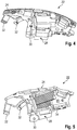
- FIGS. 4 and 5 show the inside of the frame half 22 with a view of the frame framework 28 in two conceivable embodiments.
- the laser direct structurable outer side 24 is provided with hatching, and the frame framework 28 is shown not hatched.
- the compartments formed by the frameworks 26 and 28 and receptacles for the mounting of the assemblies are comparatively clearly recognizable.
- an inside surface 34 is provided with the LDS plastic material.
- the LDS plastic material preferably has a dielectric permittivity which is increased compared with the plastic material of the frame structures 26 and 28.
- the in Fig. 5 hatched surface 34 is made of a third plastic material having a relatively high permittivity.
Landscapes
- Engineering & Computer Science (AREA)
- Manufacturing & Machinery (AREA)
- Physics & Mathematics (AREA)
- Acoustics & Sound (AREA)
- Signal Processing (AREA)
- Health & Medical Sciences (AREA)
- General Health & Medical Sciences (AREA)
- Neurosurgery (AREA)
- Otolaryngology (AREA)
- Computer Networks & Wireless Communication (AREA)
- Support Of Aerials (AREA)
- Details Of Aerials (AREA)
- Telephone Set Structure (AREA)
Abstract
Description
- Die Erfindung betrifft ein Verfahren zur Herstellung eines (Elektronik-)Tragrahmens eines Hörhilfegeräts zur Aufnahme und Halterung von elektrischen und elektronischen Baugruppen. Die Erfindung betrifft weiterhin ein nach einem derartigen Verfahren hergestellten Tragrahmen sowie ein mit einem solchen Tragrahmen versehenes Hörhilfegerät.
- Hörhilfegeräte sind tragbare Hörgeräte, die insbesondere zur Versorgung von Schwerhörenden oder Hörgeschädigten dienen. Um den zahlreichen individuellen Bedürfnissen entgegenzukommen, werden unterschiedliche Bauformen von Hörhilfegeräte wie Hinter-dem-Ohr-Hörgeräte (HdO) und Hörgeräte mit einem externen Hörer (RIC: receiver in the canal) sowie In-dem-Ohr-Hörgeräte (IdO), zum Beispiel auch Concha-Hörgeräte oder Kanal-Hörgeräte (ITE: In-The-Ear, CIC: Completely-In-Channel, IIC: Invisible-In-The-Channel), bereitgestellt. Die beispielhaft aufgeführten Hörgeräte werden am Außenohr oder im Gehörgang eines Hörhilfegerätenutzers getragen. Darüber hinaus stehen auf dem Markt aber auch Knochenleitungshörhilfen, implantierbare oder vibrotaktile Hörhilfen zur Verfügung. Dabei erfolgt die Stimulation des geschädigten Gehörs entweder mechanisch oder elektrisch.
- Derartige Hörgeräte besitzen prinzipiell als wesentliche (Hörgeräte-)Komponenten einen Eingangswandler, einen Verstärker und einen Ausgangswandler. Der Eingangswandler ist in der Regel ein akusto-elektrischer Wandler, wie beispielsweise ein Mikrofon. Der Ausgangswandler ist meist als ein elektro-akustischer Wandler, zum Beispiel als ein Miniaturlautsprecher (Hörer), oder als ein elektromechanischer Wandler, wie beispielsweise ein Knochenleitungshörer, realisiert. Der Verstärker ist üblicherweise in eine Signalverarbeitungseinrichtung integriert. Die Energieversorgung erfolgt üblicherweise durch eine Batterie oder einen aufladbaren Akkumulator.
- Derartige Hörgeräte weisen weiterhin beispielsweise ein elektromagnetischen Empfänger, beispielsweise ein Antennenelement als RF-Antenne auf, mittels welchen das Hörgerät signaltechnisch beispielsweise mit einem Bedienelement (Fernbedienung) und/oder mit einem weiteren Hörgerät koppelbar ist. In der Regel wird aus Platzgründen dasselbe Antennenelement für das Senden und das Empfangen von Daten verwendet.
- Hörgeräte sind vorzugsweise besonders platzsparend und kompakt ausgeführt, sodass sie optisch möglichst unscheinbar von einem Hörgerätenutzer getragen werden können. Dadurch werden zunehmend kleinere Hörgeräte hergestellt, welche einen zunehmend höheren Tragekomfort aufweisen, und somit von einem Benutzer bei einem Tragen an oder in einem Ohr kaum wahrgenommen werden. Aufgrund des dadurch reduzierten Bauraums ist es jedoch zunehmend schwieriger konventionelle Antennenelemente zur drahtlosen Signalübertragung in derartigen Hörgeräten unterzubringen und/oder einzubauen.
- Es sind Hörhilfegeräte mit Tragrahmen (Elektronikrahmen, Frame) mit zwei zusammensetzbaren Rahmenhälften zur Halterung und Aufnahme der elektrischen oder elektronischen Baugruppen beziehungsweise Komponenten innerhalb eines (Geräte-)Gehäuses denkbar. Derartige Tragrahmen beziehungsweise Rahmenhälften sind beispielsweise als spritzgegossene MID-Bauteile (MID: Molded Interconnected Devices) ausgeführt. Ein derartiger Tragrahmen als Schaltungsträger ist zum Beispiel aus einem laserdirektstrukturierbaren Kunststoffmaterial herstellbar, sodass das Antennenelement insbesondere mittels einer Laser-Direkt-Strukturierung (LDS) als elektrisch leitfähige Struktur in den Tragrahmen selbst integrierbar ist. Durch die Integration des Antennenelements in den Tragrahmen wird eine für eine effektive Sende-/Empfangs-Charakteristik des Antennenelements notwendige Antennenlänge auch bei bauraumreduzierten Hörhilfegeräten ermöglicht.
- Die Rahmenhälften des Tragrahmens sind somit im Wesentlichen jeweils als ein spritzgegossener Schaltungsträger ausgebildet, in den eine elektrische Leiterbahn oder Mikrostreifenleitung als Antennenelement oder Antennenstruktur eingebracht ist. Hierbei wird zur Herstellung des Tragrahmens beziehungsweise dessen Rahmenhälften ein thermoplastischer Kunststoff mit einer (nichtleitenden) laseraktivierbaren Metall-Verbindung als Kunststoff-Additiv dotiert. Die oder jede Rahmenhälfte wird hierbei mittels eines Ein-Komponenten-Spritzguss-Verfahrens aus diesem Kunststoffmaterial hergestellt. Anschließend wird mit einem Laserstrahl die spätere Leiterbahn oder Mikrostreifenleitung des Antennenelements auf den Kunststoff der Rahmenhälfte geschrieben, wobei das Kunststoff-Additiv aktiviert wird. Die aktivierten Bereiche werden anschließend lokal mit einer elektrisch leitfähigen Metallisierung als Mikrostreifenleitung oder Leiterbahn versehen.
- Nachteiligerweise weisen derartige LDS-geeignete Kunststoffmaterialien vergleichsweise schlechte mechanische Eigenschaften auf. Insbesondere die mechanische Stabilität wird bei einer Verringerung der Baugröße derartig hergestellter Bauteile nachteilig beeinflusst. Dies ist insbesondere im Bereich mechanisch beanspruchter Bauteilstellen, wie beispielsweise zur gegenseitigen Befestigung der Rahmenhälften aneinander, kritisch zu bewerten. Dadurch ist es beispielsweise notwendig, dass eine gewisse Mindestbaugröße des Tragrahmens nicht unterschritten wird, sodass eine weitere Reduzierung der Hörgerätegröße nachteilig erschwert wird, oder auf ein nicht laserdirektstrukturierbares Kunststoffmaterial mit besserer mechanischer Stabilität ausgewichen werden muss.
- Der Erfindung liegt die Aufgabe zugrunde, ein besonders geeignetes Verfahren zur Herstellung eines Tragrahmens eines Hörhilfegeräts anzugeben. Insbesondere soll der Tragrahmen zur LDS geeignet sein, und gleichzeitig eine möglichst hohe mechanische Stabilität aufweisen. Der Erfindung liegt weiterhin die Aufgabe zugrunde, ein nach einem derartigen Verfahren hergestellten Tragrahmen sowie ein mit einem solchen Tragrahmen versehenes Hörhilfegerät anzugeben.
- Hinsichtlich des Verfahrens wird die Aufgabe mit den Merkmalen des Anspruchs 1 und hinsichtlich des Tragrahmens mit den Merkmalen des Anspruchs 5 sowie hinsichtlich des Hörhilfegeräts mit den Merkmalen des Anspruchs 6 erfindungsgemäß gelöst. Vorteilhafte Ausgestaltungen und Weiterbildungen sind Gegenstand der jeweiligen Unteransprüche.
- Das erfindungsgemäße Verfahren ist zur Herstellung eines Tragrahmens eines Hörhilfegeräts geeignet und ausgestaltet. Der Tragrahmen ist zweckmäßigerweise aus zwei zusammensetzbaren Rahmenhälften gebildet, welche dazu vorgesehen und ausgeführt sind, elektrische und elektronische Baugruppen des Hörhilfegeräts aufzunehmen und in einer Position gegeneinander zu halten oder zu fixieren. Die Baugruppen sind hierbei vorzugsweise Komponenten des Hörhilfegeräts.
- Die Baugruppen umfassen hierbei eine Sende- und/oder Empfangseinheit für elektromagnetische Wellen. Unter elektromagnetischen Wellen sind nachfolgend insbesondere Funksignale, auch als RF-Signale bezeichnet, zu verstehen. Der Sende- und/oder Empfangseinheit ist ein Antennenelement zum Versenden und/oder Empfangen der RF-Signale zugeordnet, welches zumindest in eine der Rahmenhälften integriert ist. Mit anderen Worten ist das Antennenelement ein integrales Bauteil der oder jeder Rahmenhälfte ist. Dies bedeutet, dass das Antennenelement im Wesentlichen nicht von der jeweiligen Rahmenhälfte lösbar ist, und der äußeren Kontur der jeweiligen Rahmenhälfte nicht wesentlich emporsteht.
- Verfahrensgemäß ist hierbei vorgesehen, dass der Tragrahmen in einem Zwei-Komponenten-Spritzguss-Verfahren (2K-Verfahren) mit einem für eine Laser-Direkt-Strukturierung (LDS) geeigneten ersten Kunststoffmaterial und mit einem elektrisch nicht leitfähigen zweiten Kunststoffmaterial hergestellt wird, welches eine im Vergleich zum ersten Kunststoffmaterial erhöhte mechanische Stabilität aufweist. Dadurch ist ein besonders geeignetes Verfahren zu Herstellung des Tragrahmens realisiert.
- Im Gegensatz zum Stand der Technik ist der Tragrahmen somit als ein Zwei-Komponenten-Spritzgussteil hergestellt, wobei durch das mechanisch stabilere zweite Kunststoffmaterial die mechanische Stabilität des Tragrahmens vorteilhaft verbessert wird. Dadurch ist es möglich, ohne eine nachteilige Beeinflussung der mechanischen Stabilität des Tragrahmens dessen Baugröße und somit die Baugröße eines damit versehenen Hörhilfegeräts zu reduzieren.
- In einer geeigneten Weiterbildung wird das zweite Kunststoffmaterial zur Herstellung eines mechanisch stabilen Rahmengerüsts der oder jeder Rahmenhälfte verwendet, auf welches das erste Kunststoffmaterial zur Bildung einer laserdirektstrukturierbarer Oberfläche aufgebracht wird. Durch das Rahmengerüst wird eine besonders hohe mechanische Stabilität der jeweiligen Rahmenhälfte, insbesondere im Bereich von Anbindungs- oder Befestigungsstellen für eine gegenseitige Befestigung der Rahmenhälften, gewährleistet.
- In einer vorteilhaften Ausbildung des Verfahrens wird das Antennenelement mittels einer Laser-Direkt-Strukturierung des ersten Kunststoffmaterials der jeweiligen Rahmenhälfte, insbesondere der Oberfläche, erzeugt beziehungsweise in die jeweilige Rahmenhälfte/Oberfläche integriert. Dadurch ist eine besonders zweckmäßige und kostengünstige Funktionsintegration des Antennenelements in den Tragrahmen realisiert.
- In einer zweckmäßigen Ausführung weist das erste Kunststoffmaterial eine höhere dielektrische (relative) Permittivität als das zweite Kunststoffmaterial auf. Dies überträgt sich in der Folge vorteilhaft auf die Antennenleistung und/oder die Antennenlänge des Antennenelements. Die erhöhte Permittivität wirkt sich hierbei insbesondere vorteilhaft auf eine Reduzierung der benötigten Antennenlänge aus.
- Ein zusätzlicher oder weiterer Aspekt der Erfindung sieht einen nach einem derartigen Verfahren hergestellten Tragrahmen eines Hörhilfegeräts vor. Dadurch ist ein mechanisch stabiler Tragrahmen realisiert, welcher gleichzeitig für eine LDS geeignet und eingerichtet ist.
- In einer bevorzugten Anwendung ist der erfindungsgemäße Tragrahmen Teil eines Hörhilfegeräts. Der Tragrahmen ist hierbei vorzugsweise in einem Gehäuse eingesetzt, sodass das Antennenelement sowie die Baugruppen vor äußeren Einflüssen geschützt sind.
- Nachfolgend sind Ausführungsbeispiele der Erfindung anhand einer Zeichnung näher erläutert. Darin zeigen:
- Fig. 1
- in vereinfachter und schematisierter Darstellung ein Hörhilfegerät mit einem in einem Gehäuse aufgenommenen Tragrahmen,
- Fig. 2
- in perspektivischer Darstellung eine Rahmenhälfte einer konkreten Ausführungsform des Tragrahmens mit Blick auf eine Außenseite,
- Fig. 3
- die Rahmenhälfte in einer alternativen Ausführungsform in perspektivischer Darstellung,
- Fig. 4
- in perspektivischer Darstellung eine Rahmenhälfte mit Blick auf eine Innenseite, und
- Fig. 5
- eine alternative Ausführungsform der Rahmenhälfte in perspektivischen Darstellung.
- Einander entsprechende Teile und Größen sind in allen Figuren stets mit den gleichen Bezugszeichen versehen.
- In
Fig. 1 sind lediglich die wesentlichen Elemente und Komponenten eines Hörhilfegeräts 2 dargestellt, ohne deren Position, Verbindungen oder Form naturgetreu wiederzugeben. - Bei dem in
Fig. 1 dargestellten Hörhilfegerät 2 handelt es sich um ein Hörhilfegerät 2 zum Tragen hinter dem Ohr. Die Erfindung ist aber auch für In-dem-Ohr Hörhilfegeräte denkbar, wobei sich dann eine entsprechend andere Anordnung der dargestellten Komponenten ergibt. - Das Hörhilfegerät 2 weist ein schalenartiges (Geräte-)Gehäuse 4 aus Kunststoff auf, in das ein Tragrahmen 6 eingesetzt ist. Bei dem Tragrahmen 6 handelt es sich um ein Zwei-Komponenten-Spritzguss-Kunststoffteil. Der Tragrahmen 6 dient allgemein zur Aufnahme von elektrischen und elektronischen Baugruppen des Hörhilfegeräts 2 sowie zur Fixierung und Halterung dieser Baugruppen innerhalb des Gehäuses 4 in bestimmten Positionen relativ zueinander. Konkret sind in dem Tragrahmen 6 ein oder mehrere Mikrofone 8 zur Aufnahme eines Umgebungsschalls (das bedeutet eines akustischen Signals) angeordnet. In den Tragrahmen 6 ist hierzu beispielsweise ein gedruckter Schaltungsträger (Printed Circuit Board, kurz: PCB) eingefaltet, der zumindest einen Teil der besagten elektrischen oder elektronischen Komponenten trägt.
- Die Mikrofone 8 sind akusto-elektrische Wandler zur Umwandlung des akustischen Schalls in elektrische Audiosignale. Eine Signalverarbeitungseinrichtung 10, die ebenfalls in das Gehäuse 4integriert ist, ist zur Verarbeitung diese Audiosignale vorgesehen. Das Ausgangssignal der Signalverarbeitungseinrichtung 10 wird an einen Lautsprecher beziehungsweise Hörer 12 übertragen, der als elektro-akustischer Wandler ein akustisches Signal ausgibt. Der ausgegebene Schall wird gegebenenfalls über einen Schallschlauch, der mit einer Otoplastik in einem Gehörgang eines Hörhilfegerätenutzers fixiert oder fixierbar ist, zu einem Trommelfell des Hörhilfegerätenutzers übertragen.
- Die Energieversorgung des Hörhilfegeräts 2 und insbesondere die der Signalverarbeitungseinrichtung 10 erfolgt durch eine ebenfalls ins Gehäuse 4 integrierte Batterie 14. Die Signalverarbeitungseinrichtung 10, Hörer 12 und Batterie 14 sind ebenfalls in dem Tragrahmen 6 angeordnet, sodass der Tragrahmen 6 mit den darin angeordneten Komponenten einfach dem Gehäuse 4 entnommen werden kann, um beispielsweise das Gehäuse 4 austauschen zu können.
- Die Signalverarbeitungseinrichtung 10 ist zur Verarbeitung von elektromagnetischen Wellen ausgelegt und eingerichtet. Die Signalverarbeitungseinrichtung 10 weist hierzu eine Sende- und Empfangseinrichtung (Transceiver) 16 zum Erzeugen und Detektieren von elektromagnetischen Wellen und/oder zu deren Dekodierung auf. Die Sende- und Empfangseinrichtung 10 ist elektrisch mit einem Antennenelement 18 verbunden, um elektromagnetische Wellen auszusenden und zu empfangen.
- Das als RF-Antenne ausgeführte Antennenelement 18 ist als integraler Bestandteil des Tragrahmens 6, insbesondere als in den Tragrahmen 6 integrierte leitfähige Struktur, ausgebildet. Das Antennenelement 18 ist dabei - wie beispielsweise in der
Fig. 2 ersichtlich - unmittelbar auf dem Tragrahmen 6 aufgebracht. Sie ist somit nicht von der Oberfläche beabstandet und nicht zerstörungsfrei von dem Tragrahmen 6 lösbar. - Das Antennenelement 18 ist insbesondere in MID-Technologie auf dem Tragrahmen 6 aufgebracht. Hierzu wird eine Laser-Direkt-Strukturierung (Laser Direct Structuring, kurz: LDS) angewendet. Die oberflächlich auf den Tragrahmen 6 aufgebrachten Mikrostreifenleitungen beziehungsweise Leiterstrukturen werden anschließend optional durch eine Schutzlackierung oder -beschichtung elektrisch isoliert und somit vor einer Beschädigung beschützt.
- Der Tragrahmen 6 ist längs entlang einer entlang der Hörhilfegeräte-Längsrichtung orientierter Teilungsebene in zwei schalenartige Rahmenhälften 20 und 22 geteilt. Die Rahmenhälften 20 (
Fig. 2 und 3 ) und 22 (Fig. 4 und 5 ) werden hierbei nach dem Einsetzen der darin aufgenommenen Baugruppen durch Verclipsung, Verschraubung, Verklebung und/oder mittels Haltestiften verbunden. Im verbundenen (Tragrahmen-)Zustand sind die Baugruppen somit zumindest teilweise formschlüssig in nicht näher bezeichneten Ausnehmungen zwischen den Rahmenhälften 20 und 22 gehalten. - Die
Fig. 2 und 3 zeigen die Rahmenhälfte 20 in zwei beispielhaften Ausführungsformen mit Blick auf eine Außenseite 24 des Tragrahmens 6. Die Außenseite 24 ist im Montagezustand diejenige Oberfläche der Rahmenhälfte 20, die dem Gehäuse 4 zugewandt ist. In dem Ausführungsbeispiel derFig. 2 ist das Antennenelement 18 an der Außenseite 24, also an der seitlichen Oberfläche des Tragrahmens 6 angeordnet. - Der Tragrahmen 6 beziehungsweise die Rahmenhälften 20 und 22 sind als Zwei-Komponenten-Spritzgussteile aus zwei Kunststoffmaterialien hergestellt. Ein mechanisch stabiles Rahmengerüst 26 und 28 ist hierbei aus einem mechanisch stabilen Kunststoffmaterial gefertigt, welches beispielsweise einen 5 bis 20%-igen Anteil an Glasfasern aufweist. Das Rahmengerüst 26, 28 bildet hierbei die für die Aufnahme und Halterung der Baugruppen sowie die gegenseitige Befestigung notwendigen Konturen der Rahmenhälften 20 und 22.
- Das Rahmengerüst 26 beziehungsweise 28 wird anschließend als Einlegeteil zumindest abschnittsweise von dem zweiten Kunststoffmaterial umspritzt. Das zweite Kunststoffmaterial ist hierbei als ein LDS geeigneter MID-Kunststoff ausgeführt.
- Wie in den
Figuren 2 und 3 vergleichsweise deutlich ersichtlich ist, bildet das Rahmengerüst 26, 28 hierbei im Wesentlichen den inneren Teil des Tragrahmens 6, wobei die darauf aufgebrachte Oberfläche 24 aus dem LDS-Kunststoff gefertigt ist. - Die Kunststoffmaterialien des Tragrahmens 6 weisen vorzugsweise eine wesentlich höhere Permittivität auf als das Kunststoffmaterial des Gehäuses 4. Es hat sich gezeigt, dass die erhöhte Permittivität des Rahmenmaterials durch dielektrische Wechselwirkung mit dem von dem Antennenelement 18 erzeugten und empfangenen elektromagnetischen Feld eine entscheidende Verkürzung der Antennenlänge ermöglicht.
- In der
Fig. 2 ist die Rahmenhälfte 20 dargestellt. Auf die außenseitige Oberfläche 24 ist das LDS-gefertigte Antennenelement 18 aufgebracht. In derFig. 2 ist eine ösen- oder kreisringartige Befestigungsfläche 30 des Rahmengerüsts 26 der Rahmenhälfte 20 sichtbar, welche beispielsweise für eine Verstiftung mit dem Gehäuse 4 und/oder mit einem Batteriefach zur Halterung der Batterie 14 und/oder mit der Rahmenhälfte 22 ausgestaltet ist. Des Weiteren zeigtFig. 2 zwei als Rastarme oder Haken ausgebildete Halterame 32 des Rahmengerüsts 26, welche im Füge- oder Tragrahmenzustand eine On/Off-Funktionalität des Batteriefachs gewährleisten. - Die
Fig. 3 zeigt eine alternative Ausbildung der Rahmenhälfte 20 ohne das Antennenelement 18. In denFiguren 2 und 3 sind die Bereiche des Rahmengerüsts 26 der Rahmenhälfte 20, also die aus dem mechanisch stabileren Kunststoffmaterial hergestellten Teile des Tragrahmens 6, zur verbesserten Sichtbarkeit mit einer Schraffur versehen. - Die
Figuren 4 und 5 zeigen die Innenseite der Rahmenhälfte 22 mit Blick auf das Rahmengerüst 28 in zwei denkbaren Ausgestaltungsformen. In diesen Darstellungen ist die laserdirektstrukturierbare Außenseite 24 mit einer Schraffur versehen, und das Rahmengerüst 28 nicht schraffiert gezeigt. In diesen Darstellungen sind die durch die Rahmengerüste 26 und 28 ausgebildeten Fächer und Aufnahmen für die Halterung der Baugruppen vergleichsweise deutlich erkennbar. - In dem Ausführungsbeispiel der
Fig. 5 ist zusätzlich zu der Außenseite 24 eine innenseitige Oberfläche 34 mit dem LDS-Kunststoffmaterial versehen. Das LDS-Kunststoffmaterial weist hierbei vorzugsweise eine gegenüber dem Kunststoffmaterial der Rahmengerüste 26 und 28 erhöhte dielektrische Permittivität auf. Alternativ ist es beispielsweise ebenso denkbar, dass die inFig. 5 schraffiert dargestellte Oberfläche 34 aus einem dritten Kunststoffmaterial mit einer vergleichsweise hohen Permittivität hergestellt ist. - Die Erfindung ist nicht auf die vorstehend beschriebenen Ausführungsbeispiele beschränkt. Vielmehr können auch andere Varianten der Erfindung von dem Fachmann hieraus abgeleitet werden, ohne den Gegenstand der Erfindung zu verlassen. Insbesondere sind ferner alle im Zusammenhang mit den Ausführungsbeispielen beschriebenen Einzelmerkmale auch auf andere Weise miteinander kombinierbar, ohne den Gegenstand der Erfindung zu verlassen.
-
- 2
- Hörhilfegerät
- 4
- Gehäuse
- 6
- Tragrahmen
- 8
- Mikrofon
- 10
- Signalverarbeitungseinrichtung
- 12
- Hörer
- 14
- Batterie
- 16
- Sende- und Empfangseinrichtung
- 18
- Antennenelement
- 20, 22
- Rahmenhälfte
- 24
- Außenseite/Oberfläche
- 26,28
- Rahmengerüst
- 30
- Befestigungsfläche
- 32
- Haltearm
- 34
- Oberfläche
Claims (6)
- Verfahren zur Herstellung eines Tragrahmens (6) mit zwei Rahmenhälften (20, 22) zur Aufnahme und Halterung von eine Sende- und/oder Empfangseinheit (16) für elektromagnetische Wellen umfassenenden elektrischen und elektronischen Baugruppen eines Hörhilfegeräts (2), wobei in zumindest eine der Rahmenhälften (20, 22) ein Antennenelement (18) integriert ist,- wobei der Tragrahmen (6) in einem Zwei-Komponenten-Spritzguss-Verfahren mit einem für eine Laser-Direkt-Strukturierung geeigneten ersten Kunststoffmaterial und mit einem elektrisch nicht leitfähigen zweiten Kunststoffmaterial hergestellt wird, welches eine im Vergleich zum ersten Kunststoffmaterial erhöhte mechanische Stabilität aufweist.
- Verfahren nach Anspruch 1,
dadurch gekennzeichnet,
dass das zweite Kunststoffmaterial zur Herstellung eines mechanisch stabilen Rahmengerüsts (26, 28) der oder jeder Rahmenhälfte (20, 22) verwendet wird, auf welches das erste Kunststoffmaterial zur Bildung einer laserdirektstrukturierbarer Oberfläche (24, 34) aufgebracht wird. - Verfahren nach Anspruch 1 oder 2,
gekennzeichnet durch
dass das Antennenelement (18) mittels einer Laser-Direkt-Strukturierung des ersten Kunststoffmaterials der jeweiligen Rahmenhälfte (20, 22), insbesondere der Oberfläche (24), erzeugt wird. - Verfahren nach einem der Ansprüche 1 bis 3,
gekennzeichnet durch
ein erstes Kunststoffmaterial, welches eine höhere Permittivität als das zweite Kunststoffmaterial aufweist. - Tragrahmen (6) eines Hörhilfegerätes (2), hergestellt nach einem Verfahren gemäß einem der Ansprüche 1 bis 4.
- Hörhilfegerät (2) mit einem Gehäuse (4), mit einem in dem Gehäuse (4) eingesetzten Tragrahmen (6) nach Anspruch 5 zur Aufnahme und Halterung von elektrischen oder elektronischen Baugruppen, die eine Sende- und/oder Empfangseinheit (16) für elektromagnetische Wellen umfassen, sowie mit einem zugeordneten Antennenelement (18), welches als integraler Bestandteil des Tragrahmens (6) ausgebildet ist.
Applications Claiming Priority (1)
| Application Number | Priority Date | Filing Date | Title |
|---|---|---|---|
| DE102017207143.5A DE102017207143A1 (de) | 2017-04-27 | 2017-04-27 | Verfahren zur Herstellung eines Tragrahmens eines Hörhilfegeräts und Tragrahmen sowie Hörhilfegerät |
Publications (2)
| Publication Number | Publication Date |
|---|---|
| EP3396979A1 true EP3396979A1 (de) | 2018-10-31 |
| EP3396979B1 EP3396979B1 (de) | 2020-02-12 |
Family
ID=61800374
Family Applications (1)
| Application Number | Title | Priority Date | Filing Date |
|---|---|---|---|
| EP18163937.8A Revoked EP3396979B1 (de) | 2017-04-27 | 2018-03-26 | Verfahren zur herstellung eines tragrahmens eines hörhilfegeräts und tragrahmen sowie hörhilfegerät |
Country Status (5)
| Country | Link |
|---|---|
| US (1) | US20180317032A1 (de) |
| EP (1) | EP3396979B1 (de) |
| CN (1) | CN108810790A (de) |
| DE (1) | DE102017207143A1 (de) |
| DK (1) | DK3396979T3 (de) |
Families Citing this family (1)
| Publication number | Priority date | Publication date | Assignee | Title |
|---|---|---|---|---|
| DE102022203528A1 (de) * | 2022-04-07 | 2023-10-12 | Sivantos Pte. Ltd. | Hörgerät, insbesondere In-dem-Ohr-Hörgerät |
Citations (3)
| Publication number | Priority date | Publication date | Assignee | Title |
|---|---|---|---|---|
| WO2014090419A1 (de) * | 2012-12-12 | 2014-06-19 | Siemens Medical Instruments Pte. Ltd. | Modulare antenne für hörgeräte |
| US20150230035A1 (en) * | 2013-11-27 | 2015-08-13 | Starkey Laboratories, Inc. | Solderless module connector for a hearing assistance device assembly |
| WO2015139749A1 (en) * | 2014-03-20 | 2015-09-24 | Sonova Ag | Method of manufacturing a hearing device as well as a hearing device |
Family Cites Families (5)
| Publication number | Priority date | Publication date | Assignee | Title |
|---|---|---|---|---|
| DK2229009T3 (da) * | 2009-03-09 | 2014-02-03 | Oticon As | Høreapparat |
| US9374650B2 (en) | 2012-07-17 | 2016-06-21 | Starkey Laboratories, Inc. | System and method for embedding conductive traces into hearing assistance device housings |
| US9980062B2 (en) | 2012-12-12 | 2018-05-22 | Sivantos Pte. Ltd. | Hearing aid and method for producing a hearing aid |
| EP2886606B1 (de) | 2013-12-20 | 2017-11-15 | Ems-Patent Ag | Kunststoffformmasse und deren Verwendung |
| US10257624B2 (en) | 2015-08-17 | 2019-04-09 | Starkey Laboratories, Inc. | Hearing aid wireless antenna molded into the device shell |
-
2017
- 2017-04-27 DE DE102017207143.5A patent/DE102017207143A1/de not_active Withdrawn
-
2018
- 2018-03-26 EP EP18163937.8A patent/EP3396979B1/de not_active Revoked
- 2018-03-26 DK DK18163937.8T patent/DK3396979T3/da active
- 2018-04-25 CN CN201810377287.8A patent/CN108810790A/zh active Pending
- 2018-04-27 US US15/964,515 patent/US20180317032A1/en not_active Abandoned
Patent Citations (3)
| Publication number | Priority date | Publication date | Assignee | Title |
|---|---|---|---|---|
| WO2014090419A1 (de) * | 2012-12-12 | 2014-06-19 | Siemens Medical Instruments Pte. Ltd. | Modulare antenne für hörgeräte |
| US20150230035A1 (en) * | 2013-11-27 | 2015-08-13 | Starkey Laboratories, Inc. | Solderless module connector for a hearing assistance device assembly |
| WO2015139749A1 (en) * | 2014-03-20 | 2015-09-24 | Sonova Ag | Method of manufacturing a hearing device as well as a hearing device |
Also Published As
| Publication number | Publication date |
|---|---|
| EP3396979B1 (de) | 2020-02-12 |
| CN108810790A (zh) | 2018-11-13 |
| DE102017207143A1 (de) | 2018-10-31 |
| US20180317032A1 (en) | 2018-11-01 |
| DK3396979T3 (da) | 2020-05-04 |
Similar Documents
| Publication | Publication Date | Title |
|---|---|---|
| DE102008017194B4 (de) | Hörvorrichtung zum Tragen in der Ohrmuschel mit individuellem Formteil und Verfahren zum Herstellen einer Hörvorrichtung | |
| EP2932559B1 (de) | Modulare antenne für hörgeräte | |
| DE102018207179B4 (de) | Hörhilfegerät mit Elektronikrahmen und darin integrierter Antenne | |
| EP3322032B1 (de) | Hörhilfegerät mit elektronikrahmen und darin integrierter antenne | |
| EP1993324A2 (de) | Ohrpassstück mit Adapterdichtung | |
| CH673551A5 (en) | Hearing aid with direct audio input connection - provided by audio plug fitted into battery compartment upon battery removal | |
| EP3490272B1 (de) | Hörgerätecharge und verfahren zur herstellung einer hörgerätecharge | |
| WO2019105949A1 (de) | Modulares hörgerät | |
| EP3491846A1 (de) | Hörhilfegerät und hörhilfevorrichtung | |
| EP2007172B1 (de) | Schallausgangsröhrchen mit 2-Komponenten-Aufbau | |
| EP3313093A1 (de) | Hörhilfegerät und signalverarbeitungseinrichtung für ein hörhilfegerät | |
| EP2091124A2 (de) | Ladegerät für eine Hörvorrichtung mit einem bewegbaren Ladekontakt und zugehöriges Hörgerätesystem | |
| EP3396979B1 (de) | Verfahren zur herstellung eines tragrahmens eines hörhilfegeräts und tragrahmen sowie hörhilfegerät | |
| CH669296A5 (en) | Electroacoustic hearing aid with contact for external equipment - has battery compartment adapted to accept plug connection from external broadcast receiver or voice communication appts. | |
| DE102008052683B3 (de) | Hörereinrichtung und Hörgerät | |
| EP1915029B1 (de) | Hörgerät mit einer Montagevorrichtung für eine Komponente des Hörgeräts und Verfahren zum Befestigen der Komponente | |
| DE102016200831A1 (de) | Hörgerät | |
| EP2180723B1 (de) | Hörereinrichtung mit beweglichem Hörer | |
| DE102017210448B3 (de) | Hörgerät | |
| DE102017220187A1 (de) | Hörhilfegerät | |
| DE102017208445A1 (de) | Hörvorrichtung | |
| DE102006062423B4 (de) | Hörvorrichtung mit einem Schallleitstück oder Gehäuseteil aus Spritzgießkeramik | |
| DE102018201025B4 (de) | Hörgerät | |
| EP2007171B1 (de) | Verschlusseinheit mit Bauelementeträger für eine Hörvorrichtung | |
| DE102009007219A1 (de) | Faceplatemodul mit verriegelbarem Mikrofon |
Legal Events
| Date | Code | Title | Description |
|---|---|---|---|
| PUAI | Public reference made under article 153(3) epc to a published international application that has entered the european phase |
Free format text: ORIGINAL CODE: 0009012 |
|
| STAA | Information on the status of an ep patent application or granted ep patent |
Free format text: STATUS: THE APPLICATION HAS BEEN PUBLISHED |
|
| AK | Designated contracting states |
Kind code of ref document: A1 Designated state(s): AL AT BE BG CH CY CZ DE DK EE ES FI FR GB GR HR HU IE IS IT LI LT LU LV MC MK MT NL NO PL PT RO RS SE SI SK SM TR |
|
| AX | Request for extension of the european patent |
Extension state: BA ME |
|
| STAA | Information on the status of an ep patent application or granted ep patent |
Free format text: STATUS: REQUEST FOR EXAMINATION WAS MADE |
|
| 17P | Request for examination filed |
Effective date: 20190417 |
|
| RBV | Designated contracting states (corrected) |
Designated state(s): AL AT BE BG CH CY CZ DE DK EE ES FI FR GB GR HR HU IE IS IT LI LT LU LV MC MK MT NL NO PL PT RO RS SE SI SK SM TR |
|
| GRAP | Despatch of communication of intention to grant a patent |
Free format text: ORIGINAL CODE: EPIDOSNIGR1 |
|
| STAA | Information on the status of an ep patent application or granted ep patent |
Free format text: STATUS: GRANT OF PATENT IS INTENDED |
|
| INTG | Intention to grant announced |
Effective date: 20190927 |
|
| RIN1 | Information on inventor provided before grant (corrected) |
Inventor name: KUHN, JOHANNES Inventor name: NIPP, OLIVER |
|
| GRAS | Grant fee paid |
Free format text: ORIGINAL CODE: EPIDOSNIGR3 |
|
| GRAA | (expected) grant |
Free format text: ORIGINAL CODE: 0009210 |
|
| STAA | Information on the status of an ep patent application or granted ep patent |
Free format text: STATUS: THE PATENT HAS BEEN GRANTED |
|
| AK | Designated contracting states |
Kind code of ref document: B1 Designated state(s): AL AT BE BG CH CY CZ DE DK EE ES FI FR GB GR HR HU IE IS IT LI LT LU LV MC MK MT NL NO PL PT RO RS SE SI SK SM TR |
|
| REG | Reference to a national code |
Ref country code: GB Ref legal event code: FG4D Free format text: NOT ENGLISH |
|
| REG | Reference to a national code |
Ref country code: CH Ref legal event code: EP Ref country code: CH Ref legal event code: NV Representative=s name: E. BLUM AND CO. AG PATENT- UND MARKENANWAELTE , CH |
|
| REG | Reference to a national code |
Ref country code: AT Ref legal event code: REF Ref document number: 1233717 Country of ref document: AT Kind code of ref document: T Effective date: 20200215 |
|
| REG | Reference to a national code |
Ref country code: IE Ref legal event code: FG4D Free format text: LANGUAGE OF EP DOCUMENT: GERMAN |
|
| REG | Reference to a national code |
Ref country code: DE Ref legal event code: R096 Ref document number: 502018000742 Country of ref document: DE |
|
| REG | Reference to a national code |
Ref country code: DK Ref legal event code: T3 Effective date: 20200427 |
|
| PGFP | Annual fee paid to national office [announced via postgrant information from national office to epo] |
Ref country code: FR Payment date: 20200214 Year of fee payment: 3 |
|
| PG25 | Lapsed in a contracting state [announced via postgrant information from national office to epo] |
Ref country code: NO Free format text: LAPSE BECAUSE OF FAILURE TO SUBMIT A TRANSLATION OF THE DESCRIPTION OR TO PAY THE FEE WITHIN THE PRESCRIBED TIME-LIMIT Effective date: 20200512 Ref country code: FI Free format text: LAPSE BECAUSE OF FAILURE TO SUBMIT A TRANSLATION OF THE DESCRIPTION OR TO PAY THE FEE WITHIN THE PRESCRIBED TIME-LIMIT Effective date: 20200212 Ref country code: RS Free format text: LAPSE BECAUSE OF FAILURE TO SUBMIT A TRANSLATION OF THE DESCRIPTION OR TO PAY THE FEE WITHIN THE PRESCRIBED TIME-LIMIT Effective date: 20200212 |
|
| PGFP | Annual fee paid to national office [announced via postgrant information from national office to epo] |
Ref country code: DE Payment date: 20200331 Year of fee payment: 3 Ref country code: DK Payment date: 20200424 Year of fee payment: 3 |
|
| REG | Reference to a national code |
Ref country code: LT Ref legal event code: MG4D |
|
| REG | Reference to a national code |
Ref country code: NL Ref legal event code: MP Effective date: 20200212 |
|
| PG25 | Lapsed in a contracting state [announced via postgrant information from national office to epo] |
Ref country code: IS Free format text: LAPSE BECAUSE OF FAILURE TO SUBMIT A TRANSLATION OF THE DESCRIPTION OR TO PAY THE FEE WITHIN THE PRESCRIBED TIME-LIMIT Effective date: 20200612 Ref country code: HR Free format text: LAPSE BECAUSE OF FAILURE TO SUBMIT A TRANSLATION OF THE DESCRIPTION OR TO PAY THE FEE WITHIN THE PRESCRIBED TIME-LIMIT Effective date: 20200212 Ref country code: GR Free format text: LAPSE BECAUSE OF FAILURE TO SUBMIT A TRANSLATION OF THE DESCRIPTION OR TO PAY THE FEE WITHIN THE PRESCRIBED TIME-LIMIT Effective date: 20200513 Ref country code: SE Free format text: LAPSE BECAUSE OF FAILURE TO SUBMIT A TRANSLATION OF THE DESCRIPTION OR TO PAY THE FEE WITHIN THE PRESCRIBED TIME-LIMIT Effective date: 20200212 Ref country code: LV Free format text: LAPSE BECAUSE OF FAILURE TO SUBMIT A TRANSLATION OF THE DESCRIPTION OR TO PAY THE FEE WITHIN THE PRESCRIBED TIME-LIMIT Effective date: 20200212 Ref country code: BG Free format text: LAPSE BECAUSE OF FAILURE TO SUBMIT A TRANSLATION OF THE DESCRIPTION OR TO PAY THE FEE WITHIN THE PRESCRIBED TIME-LIMIT Effective date: 20200512 |
|
| PG25 | Lapsed in a contracting state [announced via postgrant information from national office to epo] |
Ref country code: NL Free format text: LAPSE BECAUSE OF FAILURE TO SUBMIT A TRANSLATION OF THE DESCRIPTION OR TO PAY THE FEE WITHIN THE PRESCRIBED TIME-LIMIT Effective date: 20200212 |
|
| PG25 | Lapsed in a contracting state [announced via postgrant information from national office to epo] |
Ref country code: LT Free format text: LAPSE BECAUSE OF FAILURE TO SUBMIT A TRANSLATION OF THE DESCRIPTION OR TO PAY THE FEE WITHIN THE PRESCRIBED TIME-LIMIT Effective date: 20200212 Ref country code: EE Free format text: LAPSE BECAUSE OF FAILURE TO SUBMIT A TRANSLATION OF THE DESCRIPTION OR TO PAY THE FEE WITHIN THE PRESCRIBED TIME-LIMIT Effective date: 20200212 Ref country code: PT Free format text: LAPSE BECAUSE OF FAILURE TO SUBMIT A TRANSLATION OF THE DESCRIPTION OR TO PAY THE FEE WITHIN THE PRESCRIBED TIME-LIMIT Effective date: 20200705 Ref country code: SM Free format text: LAPSE BECAUSE OF FAILURE TO SUBMIT A TRANSLATION OF THE DESCRIPTION OR TO PAY THE FEE WITHIN THE PRESCRIBED TIME-LIMIT Effective date: 20200212 Ref country code: ES Free format text: LAPSE BECAUSE OF FAILURE TO SUBMIT A TRANSLATION OF THE DESCRIPTION OR TO PAY THE FEE WITHIN THE PRESCRIBED TIME-LIMIT Effective date: 20200212 Ref country code: RO Free format text: LAPSE BECAUSE OF FAILURE TO SUBMIT A TRANSLATION OF THE DESCRIPTION OR TO PAY THE FEE WITHIN THE PRESCRIBED TIME-LIMIT Effective date: 20200212 Ref country code: CZ Free format text: LAPSE BECAUSE OF FAILURE TO SUBMIT A TRANSLATION OF THE DESCRIPTION OR TO PAY THE FEE WITHIN THE PRESCRIBED TIME-LIMIT Effective date: 20200212 Ref country code: SK Free format text: LAPSE BECAUSE OF FAILURE TO SUBMIT A TRANSLATION OF THE DESCRIPTION OR TO PAY THE FEE WITHIN THE PRESCRIBED TIME-LIMIT Effective date: 20200212 |
|
| REG | Reference to a national code |
Ref country code: DE Ref legal event code: R026 Ref document number: 502018000742 Country of ref document: DE |
|
| PLBI | Opposition filed |
Free format text: ORIGINAL CODE: 0009260 |
|
| PLAX | Notice of opposition and request to file observation + time limit sent |
Free format text: ORIGINAL CODE: EPIDOSNOBS2 |
|
| PG25 | Lapsed in a contracting state [announced via postgrant information from national office to epo] |
Ref country code: MC Free format text: LAPSE BECAUSE OF FAILURE TO SUBMIT A TRANSLATION OF THE DESCRIPTION OR TO PAY THE FEE WITHIN THE PRESCRIBED TIME-LIMIT Effective date: 20200212 |
|
| 26 | Opposition filed |
Opponent name: GN HEARING A/S / OTICON A/S Effective date: 20201112 |
|
| REG | Reference to a national code |
Ref country code: BE Ref legal event code: MM Effective date: 20200331 |
|
| PG25 | Lapsed in a contracting state [announced via postgrant information from national office to epo] |
Ref country code: LU Free format text: LAPSE BECAUSE OF NON-PAYMENT OF DUE FEES Effective date: 20200326 |
|
| PG25 | Lapsed in a contracting state [announced via postgrant information from national office to epo] |
Ref country code: IT Free format text: LAPSE BECAUSE OF FAILURE TO SUBMIT A TRANSLATION OF THE DESCRIPTION OR TO PAY THE FEE WITHIN THE PRESCRIBED TIME-LIMIT Effective date: 20200212 Ref country code: IE Free format text: LAPSE BECAUSE OF NON-PAYMENT OF DUE FEES Effective date: 20200326 |
|
| PG25 | Lapsed in a contracting state [announced via postgrant information from national office to epo] |
Ref country code: BE Free format text: LAPSE BECAUSE OF NON-PAYMENT OF DUE FEES Effective date: 20200331 Ref country code: PL Free format text: LAPSE BECAUSE OF FAILURE TO SUBMIT A TRANSLATION OF THE DESCRIPTION OR TO PAY THE FEE WITHIN THE PRESCRIBED TIME-LIMIT Effective date: 20200212 Ref country code: SI Free format text: LAPSE BECAUSE OF FAILURE TO SUBMIT A TRANSLATION OF THE DESCRIPTION OR TO PAY THE FEE WITHIN THE PRESCRIBED TIME-LIMIT Effective date: 20200212 |
|
| RDAF | Communication despatched that patent is revoked |
Free format text: ORIGINAL CODE: EPIDOSNREV1 |
|
| REG | Reference to a national code |
Ref country code: DE Ref legal event code: R103 Ref document number: 502018000742 Country of ref document: DE Ref country code: DE Ref legal event code: R064 Ref document number: 502018000742 Country of ref document: DE |
|
| RDAG | Patent revoked |
Free format text: ORIGINAL CODE: 0009271 |
|
| STAA | Information on the status of an ep patent application or granted ep patent |
Free format text: STATUS: PATENT REVOKED |
|
| REG | Reference to a national code |
Ref country code: CH Ref legal event code: PL |
|
| REG | Reference to a national code |
Ref country code: DK Ref legal event code: EBP Effective date: 20210331 |
|
| REG | Reference to a national code |
Ref country code: FI Ref legal event code: MGE |
|
| 27W | Patent revoked |
Effective date: 20210718 |
|
| GBPR | Gb: patent revoked under art. 102 of the ep convention designating the uk as contracting state |
Effective date: 20210718 |
|
| PG25 | Lapsed in a contracting state [announced via postgrant information from national office to epo] |
Ref country code: LI Free format text: LAPSE BECAUSE OF NON-PAYMENT OF DUE FEES Effective date: 20210331 Ref country code: CH Free format text: LAPSE BECAUSE OF NON-PAYMENT OF DUE FEES Effective date: 20210331 |
|
| REG | Reference to a national code |
Ref country code: AT Ref legal event code: MA03 Ref document number: 1233717 Country of ref document: AT Kind code of ref document: T Effective date: 20210718 |
|
| PG25 | Lapsed in a contracting state [announced via postgrant information from national office to epo] |
Ref country code: DK Free format text: LAPSE BECAUSE OF NON-PAYMENT OF DUE FEES Effective date: 20210331 |
|
| PG25 | Lapsed in a contracting state [announced via postgrant information from national office to epo] |
Ref country code: TR Free format text: LAPSE BECAUSE OF FAILURE TO SUBMIT A TRANSLATION OF THE DESCRIPTION OR TO PAY THE FEE WITHIN THE PRESCRIBED TIME-LIMIT Effective date: 20200212 Ref country code: MT Free format text: LAPSE BECAUSE OF FAILURE TO SUBMIT A TRANSLATION OF THE DESCRIPTION OR TO PAY THE FEE WITHIN THE PRESCRIBED TIME-LIMIT Effective date: 20200212 Ref country code: CY Free format text: LAPSE BECAUSE OF FAILURE TO SUBMIT A TRANSLATION OF THE DESCRIPTION OR TO PAY THE FEE WITHIN THE PRESCRIBED TIME-LIMIT Effective date: 20200212 |
|
| PG25 | Lapsed in a contracting state [announced via postgrant information from national office to epo] |
Ref country code: MK Free format text: LAPSE BECAUSE OF FAILURE TO SUBMIT A TRANSLATION OF THE DESCRIPTION OR TO PAY THE FEE WITHIN THE PRESCRIBED TIME-LIMIT Effective date: 20200212 Ref country code: AL Free format text: LAPSE BECAUSE OF FAILURE TO SUBMIT A TRANSLATION OF THE DESCRIPTION OR TO PAY THE FEE WITHIN THE PRESCRIBED TIME-LIMIT Effective date: 20200212 |
|
| PG25 | Lapsed in a contracting state [announced via postgrant information from national office to epo] |
Ref country code: FR Free format text: LAPSE BECAUSE OF NON-PAYMENT OF DUE FEES Effective date: 20210331 |
|
| PGFP | Annual fee paid to national office [announced via postgrant information from national office to epo] |
Ref country code: AT Payment date: 20260410 Year of fee payment: 4 |