EP3396776B1 - Battery cell assembly - Google Patents
Battery cell assembly Download PDFInfo
- Publication number
- EP3396776B1 EP3396776B1 EP17866407.4A EP17866407A EP3396776B1 EP 3396776 B1 EP3396776 B1 EP 3396776B1 EP 17866407 A EP17866407 A EP 17866407A EP 3396776 B1 EP3396776 B1 EP 3396776B1
- Authority
- EP
- European Patent Office
- Prior art keywords
- slanted
- end plate
- metallic
- pouch
- extension portion
- Prior art date
- Legal status (The legal status is an assumption and is not a legal conclusion. Google has not performed a legal analysis and makes no representation as to the accuracy of the status listed.)
- Active
Links
- 239000000853 adhesive Substances 0.000 claims description 45
- 230000001070 adhesive effect Effects 0.000 claims description 45
- 239000003507 refrigerant Substances 0.000 claims description 29
- 230000008878 coupling Effects 0.000 claims description 13
- 238000010168 coupling process Methods 0.000 claims description 13
- 238000005859 coupling reaction Methods 0.000 claims description 13
- XAGFODPZIPBFFR-UHFFFAOYSA-N aluminium Chemical compound [Al] XAGFODPZIPBFFR-UHFFFAOYSA-N 0.000 claims description 4
- 229910052782 aluminium Inorganic materials 0.000 claims description 4
- 239000006260 foam Substances 0.000 description 13
- 238000001816 cooling Methods 0.000 description 8
- RYGMFSIKBFXOCR-UHFFFAOYSA-N Copper Chemical compound [Cu] RYGMFSIKBFXOCR-UHFFFAOYSA-N 0.000 description 2
- 229910000831 Steel Inorganic materials 0.000 description 2
- 229910052802 copper Inorganic materials 0.000 description 2
- 239000010949 copper Substances 0.000 description 2
- 239000007769 metal material Substances 0.000 description 2
- 239000010959 steel Substances 0.000 description 2
- 238000002474 experimental method Methods 0.000 description 1
Images


Classifications
-
- H—ELECTRICITY
- H01—ELECTRIC ELEMENTS
- H01M—PROCESSES OR MEANS, e.g. BATTERIES, FOR THE DIRECT CONVERSION OF CHEMICAL ENERGY INTO ELECTRICAL ENERGY
- H01M10/00—Secondary cells; Manufacture thereof
- H01M10/60—Heating or cooling; Temperature control
- H01M10/65—Means for temperature control structurally associated with the cells
- H01M10/655—Solid structures for heat exchange or heat conduction
- H01M10/6556—Solid parts with flow channel passages or pipes for heat exchange
-
- H—ELECTRICITY
- H01—ELECTRIC ELEMENTS
- H01M—PROCESSES OR MEANS, e.g. BATTERIES, FOR THE DIRECT CONVERSION OF CHEMICAL ENERGY INTO ELECTRICAL ENERGY
- H01M10/00—Secondary cells; Manufacture thereof
- H01M10/60—Heating or cooling; Temperature control
- H01M10/61—Types of temperature control
- H01M10/613—Cooling or keeping cold
-
- H—ELECTRICITY
- H01—ELECTRIC ELEMENTS
- H01M—PROCESSES OR MEANS, e.g. BATTERIES, FOR THE DIRECT CONVERSION OF CHEMICAL ENERGY INTO ELECTRICAL ENERGY
- H01M10/00—Secondary cells; Manufacture thereof
- H01M10/60—Heating or cooling; Temperature control
- H01M10/64—Heating or cooling; Temperature control characterised by the shape of the cells
- H01M10/647—Prismatic or flat cells, e.g. pouch cells
-
- H—ELECTRICITY
- H01—ELECTRIC ELEMENTS
- H01M—PROCESSES OR MEANS, e.g. BATTERIES, FOR THE DIRECT CONVERSION OF CHEMICAL ENERGY INTO ELECTRICAL ENERGY
- H01M10/00—Secondary cells; Manufacture thereof
- H01M10/60—Heating or cooling; Temperature control
- H01M10/65—Means for temperature control structurally associated with the cells
- H01M10/653—Means for temperature control structurally associated with the cells characterised by electrically insulating or thermally conductive materials
-
- H—ELECTRICITY
- H01—ELECTRIC ELEMENTS
- H01M—PROCESSES OR MEANS, e.g. BATTERIES, FOR THE DIRECT CONVERSION OF CHEMICAL ENERGY INTO ELECTRICAL ENERGY
- H01M10/00—Secondary cells; Manufacture thereof
- H01M10/60—Heating or cooling; Temperature control
- H01M10/65—Means for temperature control structurally associated with the cells
- H01M10/655—Solid structures for heat exchange or heat conduction
- H01M10/6551—Surfaces specially adapted for heat dissipation or radiation, e.g. fins or coatings
-
- H—ELECTRICITY
- H01—ELECTRIC ELEMENTS
- H01M—PROCESSES OR MEANS, e.g. BATTERIES, FOR THE DIRECT CONVERSION OF CHEMICAL ENERGY INTO ELECTRICAL ENERGY
- H01M10/00—Secondary cells; Manufacture thereof
- H01M10/60—Heating or cooling; Temperature control
- H01M10/65—Means for temperature control structurally associated with the cells
- H01M10/655—Solid structures for heat exchange or heat conduction
- H01M10/6554—Rods or plates
-
- H—ELECTRICITY
- H01—ELECTRIC ELEMENTS
- H01M—PROCESSES OR MEANS, e.g. BATTERIES, FOR THE DIRECT CONVERSION OF CHEMICAL ENERGY INTO ELECTRICAL ENERGY
- H01M10/00—Secondary cells; Manufacture thereof
- H01M10/60—Heating or cooling; Temperature control
- H01M10/65—Means for temperature control structurally associated with the cells
- H01M10/656—Means for temperature control structurally associated with the cells characterised by the type of heat-exchange fluid
- H01M10/6567—Liquids
- H01M10/6568—Liquids characterised by flow circuits, e.g. loops, located externally to the cells or cell casings
-
- H—ELECTRICITY
- H01—ELECTRIC ELEMENTS
- H01M—PROCESSES OR MEANS, e.g. BATTERIES, FOR THE DIRECT CONVERSION OF CHEMICAL ENERGY INTO ELECTRICAL ENERGY
- H01M10/00—Secondary cells; Manufacture thereof
- H01M10/60—Heating or cooling; Temperature control
- H01M10/65—Means for temperature control structurally associated with the cells
- H01M10/656—Means for temperature control structurally associated with the cells characterised by the type of heat-exchange fluid
- H01M10/6569—Fluids undergoing a liquid-gas phase change or transition, e.g. evaporation or condensation
-
- H—ELECTRICITY
- H01—ELECTRIC ELEMENTS
- H01M—PROCESSES OR MEANS, e.g. BATTERIES, FOR THE DIRECT CONVERSION OF CHEMICAL ENERGY INTO ELECTRICAL ENERGY
- H01M50/00—Constructional details or processes of manufacture of the non-active parts of electrochemical cells other than fuel cells, e.g. hybrid cells
- H01M50/10—Primary casings; Jackets or wrappings
- H01M50/102—Primary casings; Jackets or wrappings characterised by their shape or physical structure
- H01M50/103—Primary casings; Jackets or wrappings characterised by their shape or physical structure prismatic or rectangular
-
- H—ELECTRICITY
- H01—ELECTRIC ELEMENTS
- H01M—PROCESSES OR MEANS, e.g. BATTERIES, FOR THE DIRECT CONVERSION OF CHEMICAL ENERGY INTO ELECTRICAL ENERGY
- H01M50/00—Constructional details or processes of manufacture of the non-active parts of electrochemical cells other than fuel cells, e.g. hybrid cells
- H01M50/10—Primary casings; Jackets or wrappings
- H01M50/102—Primary casings; Jackets or wrappings characterised by their shape or physical structure
- H01M50/105—Pouches or flexible bags
-
- H—ELECTRICITY
- H01—ELECTRIC ELEMENTS
- H01M—PROCESSES OR MEANS, e.g. BATTERIES, FOR THE DIRECT CONVERSION OF CHEMICAL ENERGY INTO ELECTRICAL ENERGY
- H01M50/00—Constructional details or processes of manufacture of the non-active parts of electrochemical cells other than fuel cells, e.g. hybrid cells
- H01M50/20—Mountings; Secondary casings or frames; Racks, modules or packs; Suspension devices; Shock absorbers; Transport or carrying devices; Holders
- H01M50/204—Racks, modules or packs for multiple batteries or multiple cells
- H01M50/207—Racks, modules or packs for multiple batteries or multiple cells characterised by their shape
- H01M50/211—Racks, modules or packs for multiple batteries or multiple cells characterised by their shape adapted for pouch cells
-
- H—ELECTRICITY
- H01—ELECTRIC ELEMENTS
- H01M—PROCESSES OR MEANS, e.g. BATTERIES, FOR THE DIRECT CONVERSION OF CHEMICAL ENERGY INTO ELECTRICAL ENERGY
- H01M50/00—Constructional details or processes of manufacture of the non-active parts of electrochemical cells other than fuel cells, e.g. hybrid cells
- H01M50/20—Mountings; Secondary casings or frames; Racks, modules or packs; Suspension devices; Shock absorbers; Transport or carrying devices; Holders
- H01M50/218—Mountings; Secondary casings or frames; Racks, modules or packs; Suspension devices; Shock absorbers; Transport or carrying devices; Holders characterised by the material
- H01M50/22—Mountings; Secondary casings or frames; Racks, modules or packs; Suspension devices; Shock absorbers; Transport or carrying devices; Holders characterised by the material of the casings or racks
- H01M50/222—Inorganic material
- H01M50/224—Metals
-
- H—ELECTRICITY
- H01—ELECTRIC ELEMENTS
- H01M—PROCESSES OR MEANS, e.g. BATTERIES, FOR THE DIRECT CONVERSION OF CHEMICAL ENERGY INTO ELECTRICAL ENERGY
- H01M50/00—Constructional details or processes of manufacture of the non-active parts of electrochemical cells other than fuel cells, e.g. hybrid cells
- H01M50/50—Current conducting connections for cells or batteries
- H01M50/543—Terminals
- H01M50/552—Terminals characterised by their shape
- H01M50/553—Terminals adapted for prismatic, pouch or rectangular cells
- H01M50/557—Plate-shaped terminals
-
- H—ELECTRICITY
- H01—ELECTRIC ELEMENTS
- H01M—PROCESSES OR MEANS, e.g. BATTERIES, FOR THE DIRECT CONVERSION OF CHEMICAL ENERGY INTO ELECTRICAL ENERGY
- H01M6/00—Primary cells; Manufacture thereof
- H01M6/50—Methods or arrangements for servicing or maintenance, e.g. for maintaining operating temperature
- H01M6/5038—Heating or cooling of cells or batteries
-
- H—ELECTRICITY
- H01—ELECTRIC ELEMENTS
- H01M—PROCESSES OR MEANS, e.g. BATTERIES, FOR THE DIRECT CONVERSION OF CHEMICAL ENERGY INTO ELECTRICAL ENERGY
- H01M50/00—Constructional details or processes of manufacture of the non-active parts of electrochemical cells other than fuel cells, e.g. hybrid cells
- H01M50/50—Current conducting connections for cells or batteries
- H01M50/502—Interconnectors for connecting terminals of adjacent batteries; Interconnectors for connecting cells outside a battery casing
- H01M50/503—Interconnectors for connecting terminals of adjacent batteries; Interconnectors for connecting cells outside a battery casing characterised by the shape of the interconnectors
-
- Y—GENERAL TAGGING OF NEW TECHNOLOGICAL DEVELOPMENTS; GENERAL TAGGING OF CROSS-SECTIONAL TECHNOLOGIES SPANNING OVER SEVERAL SECTIONS OF THE IPC; TECHNICAL SUBJECTS COVERED BY FORMER USPC CROSS-REFERENCE ART COLLECTIONS [XRACs] AND DIGESTS
- Y02—TECHNOLOGIES OR APPLICATIONS FOR MITIGATION OR ADAPTATION AGAINST CLIMATE CHANGE
- Y02E—REDUCTION OF GREENHOUSE GAS [GHG] EMISSIONS, RELATED TO ENERGY GENERATION, TRANSMISSION OR DISTRIBUTION
- Y02E60/00—Enabling technologies; Technologies with a potential or indirect contribution to GHG emissions mitigation
- Y02E60/10—Energy storage using batteries
Definitions
- the present invention relates to a battery cell system.
- a conventional battery system such as the ones disclosed in CN 205 621 774 , US 2016/233465 , US 2015/093608 , US 2011/212355 , EP 2 866 296 , WO 2008/078586 and US212/04221 , has a plurality of battery cells
- the battery system in order to cool the battery cells, uses a cooling system having cooling fins being disposed between the battery cells.
- the inventors herein have recognized a need for an improved battery system that utilizes metallic end plates that are coupled to end portions of pouch battery cells of a battery module to transfer heat energy from the pouch battery cells to a refrigerant flowing through the metallic end plates, without utilizing internal cooling fins disposed between the pouch battery cells.
- the present invention has been made to solve the above problems, and other technical problems that have yet to be resolved.
- the present inventors developed a battery system utilizing metallic end plates that are coupled to end portions of pouch battery cells of a battery module to transfer heat energy from the pouch battery cells to a refrigerant flowing through the metallic end plates, without utilizing internal cooling fins disposed between the pouch battery cells. And the present inventors found that the battery system can reduce its volume and weight and improve its cooling system.
- the present invention has been completed based on these findings.
- the battery system includes a first metallic end plate having a first side and a second side.
- the first side of the first metallic end plate has first and second slanted surfaces and a first groove.
- the first and second slanted surfaces of the first metallic end plate extend inwardly into the first metallic end plate and toward one another.
- the first groove of the first metallic end plate is disposed between first and second ends of the first and second slanted surfaces, respectively, of the first metallic end plate and extends further into the first metallic end plate.
- the battery system further includes a first pouch battery cell having a first pouch housing with a first end portion and a second end portion.
- the first end portion of the first pouch housing has a first extension portion and first and second slanted end surfaces.
- the first extension portion of the first pouch housing has a first end and a second end.
- the first slanted end surface of the first pouch housing extends from the first end of the first extension portion of the first pouch housing.
- the second slanted end surface of the first pouch housing extends from the first end of the first extension portion of the first pouch housing and away from the first slanted end surface of the first pouch housing.
- the battery system further includes first and second thermally conductive adhesive portions that are disposed on the first and second slanted surfaces, respectively, of the first metallic end plate.
- the first pouch battery cell is coupled to the first metallic end plate such that the first extension portion of the first pouch battery cell is disposed in the first groove of the first metallic end plate, and the first and second slanted end surfaces of the first pouch battery cell are disposed on and against the first and second thermally conductive adhesive portions, respectively, on the first and second slanted surfaces, respectively, of the first metallic end plate.
- the second side of the first metallic end plate has a first receiving bracket with first and second finger portions and a first receiving surface.
- the first receiving surface of the first metallic end plate is at least partially defined by the first and second finger portions of the first metallic end plate and extends into the first receiving bracket of the first metallic end plate.
- the battery system further includes a first conduit that is disposed against the first receiving surface of the first receiving bracket and is disposed between the first and second finger portions of the first metallic end plate.
- the first conduit has a refrigerant flowing therethrough such that the first metallic end plate transfers heat energy from the first pouch battery cell into the refrigerant.
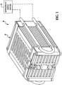
- a power supply system 10 having a battery system 20 in accordance with an exemplary embodiment, and a refrigerant supply system 22 is provided.
- the battery system 20 includes pouch battery cells, 40, 42, 44, 46, 48, 50, 52, 54, 56, 58, 60, 62, 64, 66, 68, 70, a first metallic end plate 90, a conduit 92, a second metallic end plate 100, a conduit 102, thermally conductive adhesive portions 110, 112, 114, 116, 118, 120, 122, 124, 126, 128, 130 132, 134, 136, 138, 140, 142, 144, 146, 148, 150, 152, 154, 156, 158, 160, 162, 164, 166, 168, 170, 172, 210, 212, 214, 216, 218, 220, 222, 224, 226, 228, 230, 232, 234, 236, 238, 240, 242, 244, 246, 248, 250, 252, 254, 256, 258, 260, 262, 264, 266, 268, 70, a first metallic end plate 90, a conduit 92,
- the slanted surfaces of the metallic end plate 90 can either be slanted flat surfaces as shown in FIG. 17 , or slanted arcuate-shaped surfaces (on metallic end plate 90') as shown in FIG. 18 .
- the slanted end surfaces of each pouch battery cell can either be slanted flat end surfaces as shown in FIG. 17 , or slanted arcuate-shaped end surfaces (on pouch battery cell 40') as shown in FIG. 18 coupled to thermally conductive adhesive portions 110', 112'.
- a conduit portion comprises a portion of a conduit.
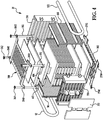
- the pouch battery cell 40 is coupled to both the first and second metallic end plates 90, 100.
- the pouch battery cell 40 includes a pouch housing 400, first and second electrical terminals 402, 404 (shown in FIG. 4 ) extending outwardly from the pouch housing 400.
- the pouch housing 400 includes a first end portion 406, a second end portion 408, and major surfaces 410, 412.
- the first end portion 406 includes an extension portion 420 and slanted end surfaces 422, 424.
- the extension portion 420 has a first end and a second end. The slanted end surface 422 extends from the first end of the extension portion 420.
- the slanted end surface 424 extends from the first end of the extension portion 420 and away from the slanted end surface 422.
- the second end portion 408 includes an extension portion 430 and slanted end surfaces 432, 434.
- the extension portion 430 has a first end and a second end.
- the slanted end surface 432 extends from the first end of the extension portion 430.
- the slanted end surface 434 extends from the first end of the extension portion 430 and away from the slanted end surface 432.
- the pouch battery cell 42 is coupled to both the first and second metallic end plates 90, 100.
- the pouch battery cell 42 includes a pouch housing 440, first and second electrical terminals (shown in FIG. 4 ) extending outwardly from the pouch housing 440.
- the pouch housing 440 includes a first end portion 446, a second end portion 448, and major surfaces 450, 452.
- the first end portion 446 includes an extension portion 460 and slanted end surfaces 462, 464.
- the extension portion 460 has a first end and a second end.
- the slanted end surface 462 extends from the first end of the extension portion 460.
- the slanted end surface 464 extends from the first end of the extension portion 460 and away from the slanted end surface 462.
- the second end portion 448 includes an extension portion 470 and slanted end surfaces 472, 474.
- the extension portion 470 has a first end and a second end.
- the slanted end surface 472 extends from the first end of the extension portion 470.
- the slanted end surface 474 extends from the first end of the extension portion 470 and away from the slanted end surface 472.
- the pouch battery cell 44 is coupled to both the first and second metallic end plates 90, 100.
- the pouch battery cell 44 includes a pouch housing 480, first and second electrical terminals extending outwardly from the pouch housing 480.
- the pouch housing 480 includes a first end portion 486, a second end portion 488, and major surfaces 490, 492.
- the first end portion 486 includes an extension portion 500 and slanted end surfaces 502, 504.
- the extension portion 500 has a first end and a second end.
- the slanted end surface 502 extends from the first end of the extension portion 500.
- the slanted end surface 504 extends from the first end of the extension portion 500 and away from the slanted end surface 502.
- the second end portion 488 includes an extension portion 510 and slanted end surfaces 512, 514.
- the extension portion 510 has a first end and a second end.
- the slanted end surface 512 extends from the first end of the extension portion 510.
- the slanted end surface 514 extends from the first end of the extension portion 510 and away from the slanted end surface 512.
- the pouch battery cell 46 is coupled to both the first and second metallic end plates 90, 100.
- the pouch battery cell 46 includes a pouch housing 520, first and second electrical terminals extending outwardly from the pouch housing 520.
- the pouch housing 520 includes a first end portion 526, a second end portion 528, and major surfaces 530, 532.
- the first end portion 526 includes an extension portion 540 and slanted end surfaces 542, 544.
- the extension portion 540 has a first end and a second end.
- the slanted end surface 542 extends from the first end of the extension portion 540.
- the slanted end surface 544 extends from the first end of the extension portion 540 and away from the slanted end surface 542.
- the second end portion 528 includes an extension portion 550 and slanted end surfaces 552, 554.
- the extension portion 550 has a first end and a second end.
- the slanted end surface 552 extends from the first end of the extension portion 550.
- the slanted end surface 554 extends from the first end of the extension portion 550 and away from the slanted end surface 552.
- the pouch battery cell 48 is coupled to both the first and second metallic end plates 90, 100.
- the pouch battery cell 48 includes a pouch housing 560, first and second electrical terminals extending outwardly from the pouch housing 560.
- the pouch housing 560 includes a first end portion 566, a second end portion 568, and major surfaces 570, 572.
- the first end portion 566 includes an extension portion 580 and slanted end surfaces 582, 584.
- the extension portion 580 has a first end and a second end.
- the slanted end surface 582 extends from the first end of the extension portion 580.
- the slanted end surface 584 extends from the first end of the extension portion 580 and away from the slanted end surface 582.
- the second end portion 568 includes an extension portion 590 and slanted end surfaces 592, 594.
- the extension portion 590 has a first end and a second end.
- the slanted end surface 592 extends from the first end of the extension portion 590.
- the slanted end surface 594 extends from the first end of the extension portion 590 and away from the slanted end surface 592.
- the pouch battery cell 50 is coupled to both the first and second metallic end plates 90, 100.
- the pouch battery cell 50 includes a pouch housing 600, first and second electrical terminals extending outwardly from the pouch housing 600.
- the pouch housing 600 includes a first end portion 606, a second end portion 608, and major surfaces 610, 612.
- the first end portion 606 includes an extension portion 620 and slanted end surfaces 622, 624.
- the extension portion 620 has a first end and a second end.
- the slanted end surface 622 extends from the first end of the extension portion 620.
- the slanted end surface 624 extends from the first end of the extension portion 620 and away from the slanted end surface 622.
- the second end portion 608 includes an extension portion 630 and slanted end surfaces 632, 634.
- the extension portion 630 has a first end and a second end.
- the slanted end surface 632 extends from the first end of the extension portion 630.
- the slanted end surface 634 extends from the first end of the extension portion 630 and away from the slanted end surface 632.
- the pouch battery cell 52 is coupled to both the first and second metallic end plates 90, 100.
- the pouch battery cell 52 includes a pouch housing 640, first and second electrical terminals extending outwardly from the pouch housing 640.
- the pouch housing 640 includes a first end portion 646, a second end portion 648, and major surfaces 650, 652.
- the first end portion 646 includes an extension portion 660 and slanted end surfaces 662, 664.
- the extension portion 660 has a first end and a second end.
- the slanted end surface 662 extends from the first end of the extension portion 660.
- the slanted end surface 664 extends from the first end of the extension portion 660 and away from the slanted end surface 662.
- the second end portion 648 includes an extension portion 670 and slanted end surfaces 672, 674.
- the extension portion 670 has a first end and a second end.
- the slanted end surface 672 extends from the first end of the extension portion 670.
- the slanted end surface 674 extends from the first end of the extension portion 670 and away from the slanted end surface 672.
- the pouch battery cell 54 is coupled to both the first and second metallic end plates 90, 100.
- the pouch battery cell 54 includes a pouch housing 680, first and second electrical terminals extending outwardly from the pouch housing 680.
- the pouch housing 680 includes a first end portion 686, a second end portion 688, and major surfaces 690, 692.
- the first end portion 686 includes an extension portion 700 and slanted end surfaces 702, 704.
- the extension portion 700 has a first end and a second end.
- the slanted end surface 702 extends from the first end of the extension portion 700.
- the slanted end surface 704 extends from the first end of the extension portion 700 and away from the slanted end surface 702.
- the second end portion 688 includes an extension portion 710 and slanted end surfaces 712, 714.
- the extension portion 710 has a first end and a second end.
- the slanted end surface 712 extends from the first end of the extension portion 710.
- the slanted end surface 714 extends from the first end of the extension portion 710 and away from the slanted end surface 712.
- the pouch battery cell 56 is coupled to both the first and second metallic end plates 90, 100.
- the pouch battery cell 56 includes a pouch housing 720, first and second electrical terminals extending outwardly from the pouch housing 720.
- the pouch housing 720 includes a first end portion 726, a second end portion 728, and major surfaces 730, 732.
- the first end portion 726 includes an extension portion 740 and slanted end surfaces 742, 744.
- the extension portion 740 has a first end and a second end.
- the slanted end surface 742 extends from the first end of the extension portion 740.
- the slanted end surface 744 extends from the first end of the extension portion 740 and away from the slanted end surface 742.
- the second end portion 728 includes an extension portion 750 and slanted end surfaces 752, 754.
- the extension portion 750 has a first end and a second end.
- the slanted end surface 752 extends from the first end of the extension portion 750.
- the slanted end surface 754 extends from the first end of the extension portion 750 and away from the slanted end surface 752.
- the pouch battery cell 58 is coupled to both the first and second metallic end plates 90, 100.
- the pouch battery cell 58 includes a pouch housing 760, first and second electrical terminals extending outwardly from the pouch housing 760.
- the pouch housing 760 includes a first end portion 766, a second end portion 768, and major surfaces 770, 772.
- the first end portion 766 includes an extension portion 780 and slanted end surfaces 782, 784.
- the extension portion 780 has a first end and a second end.
- the slanted end surface 782 extends from the first end of the extension portion 780.
- the slanted end surface 784 extends from the first end of the extension portion 780 and away from the slanted end surface 782.
- the second end portion 768 includes an extension portion 790 and slanted end surfaces 792, 794.
- the extension portion 790 has a first end and a second end.
- the slanted end surface 792 extends from the first end of the extension portion 790.
- the slanted end surface 794 extends from the first end of the extension portion 790 and away from the slanted end surface 792.
- the pouch battery cell 60 is coupled to both the first and second metallic end plates 90, 100.
- the pouch battery cell 60 includes a pouch housing 800, first and second electrical terminals extending outwardly from the pouch housing 800.
- the pouch housing 800 includes a first end portion 806, a second end portion 808, and major surfaces 810, 812.
- the first end portion 806 includes an extension portion 820 and slanted end surfaces 822, 824.
- the extension portion 820 has a first end and a second end.
- the slanted end surface 822 extends from the first end of the extension portion 820.
- the slanted end surface 824 extends from the first end of the extension portion 820 and away from the slanted end surface 822.
- the second end portion 808 includes an extension portion 830 and slanted end surfaces 832, 834.
- the extension portion 830 has a first end and a second end.
- the slanted end surface 832 extends from the first end of the extension portion 830.
- the slanted end surface 834 extends from the first end of the extension portion 830 and away from the slanted end surface 832.
- the pouch battery cell 62 is coupled to both the first and second metallic end plates 90, 100.
- the pouch battery cell 62 includes a pouch housing 840, first and second electrical terminals extending outwardly from the pouch housing 840.
- the pouch housing 840 includes a first end portion 846, a second end portion 848, and major surfaces 850, 852.
- the first end portion 846 includes an extension portion 860 and slanted end surfaces 862, 864.
- the extension portion 860 has a first end and a second end.
- the slanted end surface 862 extends from the first end of the extension portion 860.
- the slanted end surface 864 extends from the first end of the extension portion 860 and away from the slanted end surface 862.
- the second end portion 848 includes an extension portion 870 and slanted end surfaces 872, 874.
- the extension portion 870 has a first end and a second end.
- the slanted end surface 872 extends from the first end of the extension portion 870.
- the slanted end surface 874 extends from the first end of the extension portion 870 and away from the slanted end surface 872.
- the pouch battery cell 64 is coupled to both the first and second metallic end plates 90, 100.
- the pouch battery cell 64 includes a pouch housing 880, first and second electrical terminals extending outwardly from the pouch housing 880.
- the pouch housing 880 includes a first end portion 886, a second end portion 888, and major surfaces 890, 892.
- the first end portion 886 includes an extension portion 900 and slanted end surfaces 902, 904.
- the extension portion 900 has a first end and a second end.
- the slanted end surface 902 extends from the first end of the extension portion 900.
- the slanted end surface 904 extends from the first end of the extension portion 900 and away from the slanted end surface 902.
- the second end portion 888 includes an extension portion 910 and slanted end surfaces 912, 914.
- the extension portion 910 has a first end and a second end.
- the slanted end surface 912 extends from the first end of the extension portion 910.
- the slanted end surface 914 extends from the first end of the extension portion 910 and away from the slanted end surface 912.
- the pouch battery cell 66 is coupled to both the first and second metallic end plates 90, 100.
- the pouch battery cell 66 includes a pouch housing 920, first and second electrical terminals extending outwardly from the pouch housing 920.
- the pouch housing 920 includes a first end portion 926, a second end portion 928, and major surfaces 930, 932.
- the first end portion 926 includes an extension portion 940 and slanted end surfaces 942, 944.
- the extension portion 940 has a first end and a second end.
- the slanted end surface 942 extends from the first end of the extension portion 940.
- the slanted end surface 944 extends from the first end of the extension portion 940 and away from the slanted end surface 942.
- the second end portion 928 includes an extension portion 950 and slanted end surfaces 952, 954.
- the extension portion 950 has a first end and a second end.
- the slanted end surface 952 extends from the first end of the extension portion 950.
- the slanted end surface 954 extends from the first end of the extension portion 950 and away from the slanted end surface 952.
- the pouch battery cell 68 is coupled to both the first and second metallic end plates 90, 100.
- the pouch battery cell 68 includes a pouch housing 960, first and second electrical terminals extending outwardly from the pouch housing 960.
- the pouch housing 960 includes a first end portion 966, a second end portion 968, and major surfaces 970, 972.
- the first end portion 966 includes an extension portion 980 and slanted end surfaces 982, 984.
- the extension portion 980 has a first end and a second end.
- the slanted end surface 982 extends from the first end of the extension portion 980.
- the slanted end surface 984 extends from the first end of the extension portion 980 and away from the slanted end surface 982.
- the second end portion 968 includes an extension portion 990 and slanted end surfaces 992, 994.
- the extension portion 990 has a first end and a second end.
- the slanted end surface 992 extends from the first end of the extension portion 990.
- the slanted end surface 994 extends from the first end of the extension portion 990 and away from the slanted end surface 992.
- the pouch battery cell 70 is coupled to both the first and second metallic end plates 90, 100.
- the pouch battery cell 70 includes a pouch housing 1000, first and second electrical terminals extending outwardly from the pouch housing 1000.
- the pouch housing 1000 includes a first end portion 1006, a second end portion 1008, and major surfaces 1010, 1012.
- the first end portion 1006 includes an extension portion 1020 and slanted end surfaces 1022, 1024.
- the extension portion 1020 has a first end and a second end.
- the slanted end surface 1022 extends from the first end of the extension portion 1020.
- the slanted end surface 1024 extends from the first end of the extension portion 1020 and away from the slanted end surface 1022.
- the second end portion 1008 includes an extension portion 1030 and slanted end surfaces 1032, 1034.
- the extension portion 1030 has a first end and a second end.
- the slanted end surface 1032 extends from the first end of the extension portion 1030.
- the slanted end surface 1034 extends from the first end of the extension portion 1030 and away from the slanted end surface 1032.
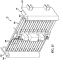
- the first metallic end plate 90 is provided to conduct heat energy from the pouch battery cells 40-70 into a refrigerant flowing through the first metallic end plate 90 from the refrigerant supply system 22.
- the first metallic end plate 90 has a first side 1300 and a second side 1302.
- the first side 1300 is coupled to the pouch battery cells 40-70.
- the second side 1302 is coupled to the conduit 92.
- the first metallic end plate 90 is constructed of aluminum.
- the first metallic end plate 90 could be constructed of other thermally conductive metallic materials such as copper or steel for example.
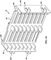
- the first side 1300 has slanted surfaces 1310, 1312 and a groove 1314; slanted surfaces 1320, 1322 and a groove 1324; slanted surfaces 1330, 1332 and a groove 1334; slanted surfaces 1340, 1342 and a groove 1344; slanted surfaces 1350, 1352 and a groove 1354; slanted surfaces 1360, 1362 and a groove 1364; slanted surfaces 1370, 1372 and a groove 1374; slanted surfaces 1380, 1382 and a groove 1384; slanted surfaces 1390, 1392 and a groove 1394; slanted surfaces 1400, 1402 and a groove 1404; slanted surfaces 1410, 1412 and a groove 1414; slanted surfaces 1420, 1422 and a groove 1424; slanted surfaces 1430, 1432 and a groove 1434; slanted surfaces 1440, 1442 and a groove 1444; slanted surfaces 1450, 1452
- the slanted surfaces 1310, 1312 extend inwardly into the first metallic end plate 90 and toward one another.
- the groove 1314 is disposed between first and second ends of the slanted surfaces 1310, 1312, respectively, and extends further into the first metallic end plate 90.
- the pouch battery cell 40 is coupled to the first metallic end plate 90 such that the extension portion 420 of the pouch battery cell 40 is disposed in the groove 1314 of the first metallic end plate 90, and the slanted end surfaces 422, 424 of the pouch battery cell 40 are disposed on and against the thermally conductive adhesive portions 110, 112, respectively, on the slanted surfaces 1310, 1312, respectively, of the first metallic end plate 90.
- the slanted surfaces 1320, 1322 extend inwardly into the first metallic end plate 90 and toward one another.
- the groove 1324 is disposed between first and second ends of the slanted surfaces 1320, 1322, respectively, and extends further into the first metallic end plate 90.
- the pouch battery cell 42 is coupled to the first metallic end plate 90 such that the extension portion 460 of the pouch battery cell 42 is disposed in the groove 1324 of the first metallic end plate 90, and the slanted end surfaces 462, 464 of the pouch battery cell 42 are disposed on and against the thermally conductive adhesive portions 114, 116, respectively, on the slanted surfaces 1320, 1322, respectively, of the first metallic end plate 90.
- the slanted surfaces 1330, 1332 extend inwardly into the first metallic end plate 90 and toward one another.
- the groove 1334 is disposed between first and second ends of the slanted surfaces 1330, 1332, respectively, and extends further into the first metallic end plate 90.
- the pouch battery cell 44 is coupled to the first metallic end plate 90 such that the extension portion 500 of the pouch battery cell 44 is disposed in the groove 1334 of the first metallic end plate 90, and the slanted end surfaces 502, 504 of the pouch battery cell 44 are disposed on and against the thermally conductive adhesive portions 118, 120, respectively, on the slanted surfaces 1330, 1332, respectively, of the first metallic end plate 90.
- the slanted surfaces 1340, 1342 extend inwardly into the first metallic end plate 90 and toward one another.
- the groove 1344 is disposed between first and second ends of the slanted surfaces 1340, 1342, respectively, and extends further into the first metallic end plate 90.
- the pouch battery cell 46 is coupled to the first metallic end plate 90 such that the extension portion 540 of the pouch battery cell 46 is disposed in the groove 1344 of the first metallic end plate 90, and the slanted end surfaces 542, 544 of the pouch battery cell 46 are disposed on and against the thermally conductive adhesive portions 122, 124, respectively, on the slanted surfaces 1340, 1342, respectively, of the first metallic end plate 90.
- the slanted surfaces 1350, 1352 extend inwardly into the first metallic end plate 90 and toward one another.
- the groove 1354 is disposed between first and second ends of the slanted surfaces 1350, 1352, respectively, and extends further into the first metallic end plate 90.
- the pouch battery cell 48 is coupled to the first metallic end plate 90 such that the extension portion 580 of the pouch battery cell 48 is disposed in the groove 1354 of the first metallic end plate 90, and the slanted end surfaces 582, 584 of the pouch battery cell 48 are disposed on and against the thermally conductive adhesive portions 126, 128, respectively, on the slanted surfaces 1350, 1352, respectively, of the first metallic end plate 90.
- the slanted surfaces 1360, 1362 extend inwardly into the first metallic end plate 90 and toward one another.
- the groove 1364 is disposed between first and second ends of the slanted surfaces 1360, 1362, respectively, and extends further into the first metallic end plate 90.
- the pouch battery cell 50 is coupled to the first metallic end plate 90 such that the extension portion 620 of the pouch battery cell 50 is disposed in the groove 1364 of the first metallic end plate 90, and the slanted end surfaces 622, 624 of the pouch battery cell 50 are disposed on and against the thermally conductive adhesive portions 130, 132, respectively, on the slanted surfaces 1360, 1362, respectively, of the first metallic end plate 90.
- the slanted surfaces 1370, 1372 extend inwardly into the first metallic end plate 90 and toward one another.
- the groove 1374 is disposed between first and second ends of the slanted surfaces 1370, 1372, respectively, and extends further into the first metallic end plate 90.
- the pouch battery cell 52 is coupled to the first metallic end plate 90 such that the extension portion 660 of the pouch battery cell 52 is disposed in the groove 1374 of the first metallic end plate 90, and the slanted end surfaces 662, 664 of the pouch battery cell 52 are disposed on and against the thermally conductive adhesive portions 134, 136, respectively, on the slanted surfaces 1370, 1372, respectively, of the first metallic end plate 90.
- the slanted surfaces 1380, 1382 extend inwardly into the first metallic end plate 90 and toward one another.
- the groove 1384 is disposed between first and second ends of the slanted surfaces 1380, 1382, respectively, and extends further into the first metallic end plate 90.
- the pouch battery cell 54 is coupled to the first metallic end plate 90 such that the extension portion 700 of the pouch battery cell 54 is disposed in the groove 1384 of the first metallic end plate 90, and the slanted end surfaces 702, 704 of the pouch battery cell 54 are disposed on and against the thermally conductive adhesive portions 138, 140, respectively, on the slanted surfaces 1380, 1382, respectively, of the first metallic end plate 90.
- the slanted surfaces 1390, 1392 extend inwardly into the first metallic end plate 90 and toward one another.
- the groove 1394 is disposed between first and second ends of the slanted surfaces 1390, 1392, respectively, and extends further into the first metallic end plate 90.
- the pouch battery cell 56 is coupled to the first metallic end plate 90 such that the extension portion 740 of the pouch battery cell 56 is disposed in the groove 1394 of the first metallic end plate 90, and the slanted end surfaces 742, 744 of the pouch battery cell 56 are disposed on and against the thermally conductive adhesive portions 142, 144, respectively, on the slanted surfaces 1390, 1392, respectively, of the first metallic end plate 90.
- the slanted surfaces 1400, 1402 extend inwardly into the first metallic end plate 90 and toward one another.
- the groove 1404 is disposed between first and second ends of the slanted surfaces 1400, 1402, respectively, and extends further into the first metallic end plate 90.
- the pouch battery cell 58 is coupled to the first metallic end plate 90 such that the extension portion 780 of the pouch battery cell 58 is disposed in the groove 1404 of the first metallic end plate 90, and the slanted end surfaces 782, 784 of the pouch battery cell 58 are disposed on and against the thermally conductive adhesive portions 146, 148, respectively, on the slanted surfaces 1400, 1402, respectively, of the first metallic end plate 90.
- the slanted surfaces 1410, 1412 extend inwardly into the first metallic end plate 90 and toward one another.
- the groove 1414 is disposed between first and second ends of the slanted surfaces 1410, 1412, respectively, and extends further into the first metallic end plate 90.
- the pouch battery cell 60 is coupled to the first metallic end plate 90 such that the extension portion 820 of the pouch battery cell 60 is disposed in the groove 1414 of the first metallic end plate 90, and the slanted end surfaces 822, 824 of the pouch battery cell 60 are disposed on and against the thermally conductive adhesive portions 150, 152, respectively, on the slanted surfaces 1410, 1412, respectively, of the first metallic end plate 90.
- the slanted surfaces 1420, 1422 extend inwardly into the first metallic end plate 90 and toward one another.
- the groove 1424 is disposed between first and second ends of the slanted surfaces 1420, 1422, respectively, and extends further into the first metallic end plate 90.
- the pouch battery cell 62 is coupled to the first metallic end plate 90 such that the extension portion 860 of the pouch battery cell 62 is disposed in the groove 1424 of the first metallic end plate 90, and the slanted end surfaces 862, 864 of the pouch battery cell 62 are disposed on and against the thermally conductive adhesive portions 154, 156, respectively, on the slanted surfaces 1420, 1422, respectively, of the first metallic end plate 90.
- the slanted surfaces 1430, 1432 extend inwardly into the first metallic end plate 90 and toward one another.
- the groove 1434 is disposed between first and second ends of the slanted surfaces 1430, 1432, respectively, and extends further into the first metallic end plate 90.
- the pouch battery cell 64 is coupled to the first metallic end plate 90 such that the extension portion 900 of the pouch battery cell 64 is disposed in the groove 1434 of the first metallic end plate 90, and the slanted end surfaces 902, 904 of the pouch battery cell 64 are disposed on and against the thermally conductive adhesive portions 158, 160, respectively, on the slanted surfaces 1430, 1432, respectively, of the first metallic end plate 90.
- the slanted surfaces 1440, 1442 extend inwardly into the first metallic end plate 90 and toward one another.
- the groove 1444 is disposed between first and second ends of the slanted surfaces 1440, 1442, respectively, and extends further into the first metallic end plate 90.
- the pouch battery cell 66 is coupled to the first metallic end plate 90 such that the extension portion 940 of the pouch battery cell 66 is disposed in the groove 1444 of the first metallic end plate 90, and the slanted end surfaces 942, 944 of the pouch battery cell 66 are disposed on and against the thermally conductive adhesive portions 162, 164, respectively, on the slanted surfaces 1440, 1442, respectively, of the first metallic end plate 90.
- the slanted surfaces 1450, 1452 extend inwardly into the first metallic end plate 90 and toward one another.
- the groove 1454 is disposed between first and second ends of the slanted surfaces 1450, 1452, respectively, and extends further into the first metallic end plate 90.
- the pouch battery cell 68 is coupled to the first metallic end plate 90 such that the extension portion 980 of the pouch battery cell 68 is disposed in the groove 1454 of the first metallic end plate 90, and the slanted end surfaces 982, 984 of the pouch battery cell 68 are disposed on and against the thermally conductive adhesive portions 166, 168, respectively, on the slanted surfaces 1450, 1452, respectively, of the first metallic end plate 90.
- the slanted surfaces 1460, 1462 extend inwardly into the first metallic end plate 90 and toward one another.
- the groove 1464 is disposed between first and second ends of the slanted surfaces 1460, 1462, respectively, and extends further into the first metallic end plate 90.
- the pouch battery cell 70 is coupled to the first metallic end plate 90 such that the extension portion 1020 of the pouch battery cell 70 is disposed in the groove 1464 of the first metallic end plate 90, and the slanted end surfaces 1022, 1024 of the pouch battery cell 70 are disposed on and against the thermally conductive adhesive portions 170, 172, respectively, on the slanted surfaces 1460, 1462, respectively, of the first metallic end plate 90.
- the second side 1302 of the first metallic end plate 90 has receiving brackets 1500, 1502 for holding the conduit 92 therein.
- the receiving bracket 1500 has first and second finger portions 1510, 1512 and a receiving surface 1514.
- the receiving surface 1514 is at least partially defined by the first and second finger portions 1510, 1512 and extends into the receiving bracket 1500.
- the receiving bracket 1502 has first and second finger portions 1520, 1522 and a receiving surface 1524.
- the receiving surface 1524 is at least partially defined by the first and second finger portions 1520, 1522 and extends into the receiving bracket 1502.
- the conduit 92 is disposed against the receiving surface 1514 of the receiving bracket 1500 and is disposed between the finger portions 1510, 1512 of the first metallic end plate 90. Also, the conduit 92 is disposed against the receiving surface 1524 of the receiving bracket 1502 and is disposed between the finger portions 1520, 1522 of the first metallic end plate 90.
- the conduit 92 has a refrigerant flowing therethrough from the refrigerant supply system 22 such that the first metallic end plate 90 transfers heat energy from the pouch battery cells 40-70 into the refrigerant.
- the conduit 92 may be coupled to the receiving surfaces 1514, 1524 utilizing a thermally conductive adhesive disposed therebetween.
- the second metallic end plate 100 is provided to conduct heat energy from the pouch battery cells 40-70 into a refrigerant flowing through the second metallic end plate 100 from the refrigerant supply system 22.
- the second metallic end plate 100 has a first side 2300 and a second side 2302.
- the first side 2300 is coupled to the pouch battery cells 40-70.
- the second side 2302 is coupled to the conduit 102.
- the second metallic end plate 100 is constructed of aluminum.
- the second metallic end plate 100 could be constructed of other thermally conductive metallic materials such as copper or steel for example.
- the first side 2300 has slanted surfaces 2310, 2312 and a groove 2314; slanted surfaces 2320, 2322 and a groove 2324; slanted surfaces 2330, 2332 and a groove 2334; slanted surfaces 2340, 2342 and a groove 2344; slanted surfaces 2350, 2352 and a groove 2354; slanted surfaces 2360, 2362 and a groove 2364; slanted surfaces 2370, 2372 and a groove 2374; slanted surfaces 2380, 2382 and a groove 2384; slanted surfaces 2390, 2392 and a groove 2394; slanted surfaces 2400, 2402 and a groove 2404; slanted surfaces 2410, 2412 and a groove 2414; slanted surfaces 2420, 2422 and a groove 2424; slanted surfaces 2430, 2432 and a groove 2434; slanted surfaces 2440, 2442 and a groove 2444; slanted surfaces 2450, 2452
- the slanted surfaces 2310, 2312 extend inwardly into the second metallic end plate 100 and toward one another.
- the groove 2314 is disposed between first and second ends of the slanted surfaces 2310, 2312, respectively, and extends further into the second metallic end plate 100.
- the pouch battery cell 40 is coupled to the second metallic end plate 100 such that the extension portion 430 of the pouch battery cell 40 is disposed in the groove 2314 of the second metallic end plate 100, and the slanted end surfaces 432, 434 of the pouch battery cell 40 are disposed on and against the thermally conductive adhesive portions 210, 212, respectively, on the slanted surfaces 2310, 2312, respectively, of the second metallic end plate 100.
- the slanted surfaces 2320, 2322 extend inwardly into the second metallic end plate 100 and toward one another.
- the groove 2324 is disposed between first and second ends of the slanted surfaces 2320, 2322, respectively, and extends further into the second metallic end plate 100.
- the pouch battery cell 42 is coupled to the second metallic end plate 100 such that the extension portion 470 of the pouch battery cell 42 is disposed in the groove 2324 of the second metallic end plate 100, and the slanted end surfaces 472, 474 of the pouch battery cell 42 are disposed on and against the thermally conductive adhesive portions 214, 216, respectively, on the slanted surfaces 2320, 2322, respectively, of the second metallic end plate 100.
- the slanted surfaces 2330, 2332 extend inwardly into the second metallic end plate 100 and toward one another.
- the groove 2334 is disposed between first and second ends of the slanted surfaces 2330, 2332, respectively, and extends further into the second metallic end plate 100.
- the pouch battery cell 44 is coupled to the second metallic end plate 100 such that the extension portion 510 of the pouch battery cell 44 is disposed in the groove 2334 of the second metallic end plate 100, and the slanted end surfaces 512, 514 of the pouch battery cell 44 are disposed on and against the thermally conductive adhesive portions 218, 220, respectively, on the slanted surfaces 2330, 2332, respectively, of the second metallic end plate 100.
- the slanted surfaces 2340, 2342 extend inwardly into the second metallic end plate 100 and toward one another.
- the groove 2344 is disposed between first and second ends of the slanted surfaces 2340, 2342, respectively, and extends further into the second metallic end plate 100.
- the pouch battery cell 46 is coupled to the second metallic end plate 100 such that the extension portion 550 of the pouch battery cell 46 is disposed in the groove 2344 of the second metallic end plate 100, and the slanted end surfaces 552, 554 of the pouch battery cell 46 are disposed on and against the thermally conductive adhesive portions 222, 224, respectively, on the slanted surfaces 2340, 2342, respectively, of the second metallic end plate 100.
- the slanted surfaces 2350, 2352 extend inwardly into the second metallic end plate 100 and toward one another.
- the groove 2354 is disposed between first and second ends of the slanted surfaces 2350, 2352, respectively, and extends further into the second metallic end plate 100.
- the pouch battery cell 48 is coupled to the second metallic end plate 100 such that the extension portion 590 of the pouch battery cell 48 is disposed in the groove 2354 of the second metallic end plate 100, and the slanted end surfaces 592, 594 of the pouch battery cell 48 are disposed on and against the thermally conductive adhesive portions 226, 228, respectively, on the slanted surfaces 2350, 2352, respectively, of the second metallic end plate 100.
- the slanted surfaces 2360, 2362 extend inwardly into the second metallic end plate 100 and toward one another.
- the groove 2364 is disposed between first and second ends of the slanted surfaces 2360, 2362, respectively, and extends further into the second metallic end plate 100.
- the pouch battery cell 50 is coupled to the second metallic end plate 100 such that the extension portion 630 of the pouch battery cell 50 is disposed in the groove 2364 of the second metallic end plate 100, and the slanted end surfaces 632, 634 of the pouch battery cell 50 are disposed on and against the thermally conductive adhesive portions 230, 232, respectively, on the slanted surfaces 2360, 2362, respectively, of the second metallic end plate 100.
- the slanted surfaces 2370, 2372 extend inwardly into the second metallic end plate 100 and toward one another.
- the groove 2374 is disposed between first and second ends of the slanted surfaces 2370, 2372, respectively, and extends further into the second metallic end plate 100.
- the pouch battery cell 52 is coupled to the second metallic end plate 100 such that the extension portion 670 of the pouch battery cell 52 is disposed in the groove 2374 of the second metallic end plate 100, and the slanted end surfaces 672, 674 of the pouch battery cell 52 are disposed on and against the thermally conductive adhesive portions 234, 236, respectively, on the slanted surfaces 2370, 2372, respectively, of the second metallic end plate 100.
- the slanted surfaces 2380, 2382 extend inwardly into the second metallic end plate 100 and toward one another.
- the groove 2384 is disposed between first and second ends of the slanted surfaces 2380, 2382, respectively, and extends further into the second metallic end plate 100.
- the pouch battery cell 54 is coupled to the second metallic end plate 100 such that the extension portion 710 of the pouch battery cell 54 is disposed in the groove 2384 of the second metallic end plate 100, and the slanted end surfaces 712, 714 of the pouch battery cell 54 are disposed on and against the thermally conductive adhesive portions 238, 240, respectively, on the slanted surfaces 2380, 2382, respectively, of the second metallic end plate 100.
- the slanted surfaces 2390, 2392 extend inwardly into the second metallic end plate 100 and toward one another.
- the groove 2394 is disposed between first and second ends of the slanted surfaces 2390, 2392, respectively, and extends further into the second metallic end plate 100.
- the pouch battery cell 56 is coupled to the second metallic end plate 100 such that the extension portion 750 of the pouch battery cell 56 is disposed in the groove 2394 of the second metallic end plate 100, and the slanted end surfaces 752, 754 of the pouch battery cell 56 are disposed on and against the thermally conductive adhesive portions 242, 244, respectively, on the slanted surfaces 2390, 2392, respectively, of the second metallic end plate 100.
- the slanted surfaces 2400, 2402 extend inwardly into the second metallic end plate 100 and toward one another.
- the groove 2404 is disposed between first and second ends of the slanted surfaces 2400, 2402, respectively, and extends further into the second metallic end plate 100.
- the pouch battery cell 58 is coupled to the second metallic end plate 100 such that the extension portion 790 of the pouch battery cell 58 is disposed in the groove 2404 of the second metallic end plate 100, and the slanted end surfaces 792, 794 of the pouch battery cell 58 are disposed on and against the thermally conductive adhesive portions 246, 248, respectively, on the slanted surfaces 2400, 2402, respectively, of the second metallic end plate 100.
- the slanted surfaces 2410, 2412 extend inwardly into the second metallic end plate 100 and toward one another.
- the groove 2414 is disposed between first and second ends of the slanted surfaces 2410, 2412, respectively, and extends further into the second metallic end plate 100.
- the pouch battery cell 60 is coupled to the second metallic end plate 100 such that the extension portion 830 of the pouch battery cell 60 is disposed in the groove 21414 of the second metallic end plate 100, and the slanted end surfaces 832, 834 of the pouch battery cell 60 are disposed on and against the thermally conductive adhesive portions 250, 252, respectively, on the slanted surfaces 2410, 2412, respectively, of the second metallic end plate 100.
- the slanted surfaces 2420, 2422 extend inwardly into the second metallic end plate 100 and toward one another.
- the groove 2424 is disposed between first and second ends of the slanted surfaces 2420, 2422, respectively, and extends further into the second metallic end plate 100.
- the pouch battery cell 62 is coupled to the second metallic end plate 100 such that the extension portion 870 of the pouch battery cell 62 is disposed in the groove 2424 of the second metallic end plate 100, and the slanted end surfaces 872, 874 of the pouch battery cell 62 are disposed on and against the thermally conductive adhesive portions 254, 256, respectively, on the slanted surfaces 2420, 2422, respectively, of the second metallic end plate 100.
- the slanted surfaces 2430, 2432 extend inwardly into the second metallic end plate 100 and toward one another.
- the groove 2434 is disposed between first and second ends of the slanted surfaces 2430, 2432, respectively, and extends further into the second metallic end plate 100.
- the pouch battery cell 64 is coupled to the second metallic end plate 100 such that the extension portion 910 of the pouch battery cell 64 is disposed in the groove 2434 of the second metallic end plate 100, and the slanted end surfaces 912, 914 of the pouch battery cell 64 are disposed on and against the thermally conductive adhesive portions 258, 260, respectively, on the slanted surfaces 2430, 2432, respectively, of the second metallic end plate 100.
- the slanted surfaces 2440, 2442 extend inwardly into the second metallic end plate 100 and toward one another.
- the groove 2444 is disposed between first and second ends of the slanted surfaces 2440, 2442, respectively, and extends further into the second metallic end plate 100.
- the pouch battery cell 66 is coupled to the second metallic end plate 100 such that the extension portion 950 of the pouch battery cell 66 is disposed in the groove 2444 of the second metallic end plate 100, and the slanted end surfaces 952, 954 of the pouch battery cell 66 are disposed on and against the thermally conductive adhesive portions 262, 264, respectively, on the slanted surfaces 2440, 2442, respectively, of the second metallic end plate 100.
- the slanted surfaces 2450, 2452 extend inwardly into the second metallic end plate 100 and toward one another.
- the groove 2454 is disposed between first and second ends of the slanted surfaces 2450, 2452, respectively, and extends further into the second metallic end plate 100.
- the pouch battery cell 68 is coupled to the second metallic end plate 100 such that the extension portion 990 of the pouch battery cell 68 is disposed in the groove 2454 of the second metallic end plate 100, and the slanted end surfaces 992, 994 of the pouch battery cell 68 are disposed on and against the thermally conductive adhesive portions 266, 268, respectively, on the slanted surfaces 2450, 2452, respectively, of the second metallic end plate 100.
- the slanted surfaces 2460, 2462 extend inwardly into the second metallic end plate 100 and toward one another.
- the groove 2464 is disposed between first and second ends of the slanted surfaces 2460, 2462, respectively, and extends further into the second metallic end plate 100.
- the pouch battery cell 70 is coupled to the second metallic end plate 100 such that the extension portion 1030 of the pouch battery cell 70 is disposed in the groove 2464 of the second metallic end plate 100, and the slanted end surfaces 1032, 1034 of the pouch battery cell 70 are disposed on and against the thermally conductive adhesive portions 270, 272, respectively, on the slanted surfaces 2460, 2462, respectively, of the second metallic end plate 100.
- the second side 2302 of the second metallic end plate 100 has receiving brackets 2500, 2502 for holding the conduit 102 therein.
- the receiving bracket 2500 has first and second finger portions 2510, 2512 and a receiving surface 2514.
- the receiving surface 2514 is at least partially defined by the first and second finger portions 2510, 2512 and extends into the receiving bracket 2500.
- the receiving bracket 2502 has first and second finger portions 2520, 2522 and a receiving surface 2524.
- the receiving surface 2524 is at least partially defined by the first and second finger portions 2520, 2522 and extends into the receiving bracket 2502.
- the conduit 102 is disposed against the receiving surface 2514 of the receiving bracket 2500 and is disposed between the finger portions 2510, 2512 of the second metallic end plate 100. Also, the conduit 102 is disposed against the receiving surface 2524 of the receiving bracket 2502 and is disposed between the finger portions 2520, 2522 of the second metallic end plate 100.
- the conduit 102 has a refrigerant flowing therethrough from the refrigerant supply system 22 such that the second metallic end plate 100 transfers heat energy from the pouch battery cells 40-70 into the refrigerant.
- the conduit 102 may be coupled to the receiving surfaces 2514, 2524 utilizing a thermally conductive adhesive disposed therebetween.
- the end plate 300 includes apertures 2640, 2642, 2650, 2652 extending therethrough.
- the end plate 300 is disposed against first ends of the first and second metallic end plates 90, 100, and is further disposed against the foam layer 310.
- the end plate 302 includes apertures 2740, 2742, 2750, 2752 extending therethrough.
- the end plate 302 is disposed against second ends of the first and second metallic end plates 90, 100, and is further disposed against the foam layer 326.
- the shaft members 340, 342, 350, 352 extend through apertures 2640, 2642, 2650, 2652, respectively, in the end plate 300, and further extend through apertures 2740, 2742, 2750, 2752, respectively, in the end plate 302 to couple the end plates 300, 302 to one another such that the pouch battery cells 40-72 and the foam layers 310-326 are fixedly held between the end plates 300, 302.
- the foam layer 310 is disposed between and contacts both the end plate 300 and a major surface 410 of the pouch battery cell 40.
- the foam layer 312 is disposed between and contacts both a major surface 452 of the pouch battery cell 42 and a major surface 490 of the pouch battery cell 44.
- the foam layer 314 is disposed between and contacts both a major surface 532 of the pouch battery cell 46 and a major surface 570 of the pouch battery cell 48.
- the foam layer 316 is disposed between and contacts both a major surface 612 of the pouch battery cell 50 and a major surface 652 of the pouch battery cell 52.
- the foam layer 318 is disposed between and contacts both a major surface 692 of the pouch battery cell 54 and a major surface 730 of the pouch battery cell 56.
- the foam layer 320 is disposed between and contacts both a major surface 772 of the pouch battery cell 58 and a major surface 810 of the pouch battery cell 60.
- the foam layer 322 is disposed between and contacts both a major surface 852 of the pouch battery cell 62 and a major surface 890 of the pouch battery cell 64.
- the foam layer 324 is disposed between and contacts both a major surface 932 of the pouch battery cell 66 and a major surface 970 of the pouch battery cell 68.
- the foam layer 326 is disposed between and contacts both a major surface 1012 of the pouch battery cell 70 and the end plate 302.
- the interconnect board 330 is disposed between and is coupled to the end plates 300, 302.
- the interconnect board 330 electrically couples the pouch battery cells 40-70 to one another utilizing a plurality electrical tabs 2830.
- the interconnect board 330 includes a central wall 2800, a first side wall 2802, a second side wall 2804, C-shaped coupling tabs 2810, 2812, 2814, 2816, and the plurality electrical tabs 2830.
- the central wall 2800, the first side wall 2802, the second side wall 2004, and the C-shaped coupling tabs 2810, 2812, 2814, 2816 are constructed of plastic.
- the first side wall 2802 is coupled to a first end of the central wall 2800.
- the first side wall 2802 includes an aperture 2840 extending therethrough that is configured to receive the shaft member 340 (shown in FIG. 4 ) therethrough.
- the second side wall 2804 is coupled to a second end of the central wall 2800.
- the second side wall 2804 includes an aperture 2850 extending therethrough that is configured to receive the shaft member 350 (shown in FIG. 4 ) therethrough.
- the C-shaped coupling tabs 2810, 2812 are coupled to and extend outwardly from the first side wall 2802.
- the C-shaped coupling tabs 2810, 2812 are configured to hold portions of the conduit 92 therein.
- the C-shaped coupling tabs 2814, 2816 are coupled to and extend outwardly from the second side wall 2804.
- the C-shaped coupling tabs 2814, 2816 are configured to hold portions of the conduit 102 therein.
- the side member 334 is disposed between and is coupled to the end plates 300, 302.
- the side member 334 includes a central wall 2900, a first side wall 2902, a second side wall 2904, C-shaped coupling tabs 2910, 2912, 2914, 2916.
- the central wall 2900, the first side wall 2902, the second side wall 2904, and the C-shaped coupling tabs 2910, 2912, 2914, 2916 are constructed of plastic.
- the first side wall 2902 is coupled to a first end of the central wall 2900.
- the first side wall 2902 includes an aperture 2942 extending therethrough that is configured to receive the shaft member 342 (shown in FIG. 4 ) therethrough.
- the second side wall 2904 is coupled to a second end of the central wall 2900.
- the second side wall 2904 includes an aperture 2952 extending therethrough that is configured to receive the shaft member 352 (shown in FIG. 4 ) therethrough.
- the C-shaped coupling tabs 2910, 2912 are coupled to and extend outwardly from the first side wall 2902.
- the C-shaped coupling tabs 2910, 2912 are configured to hold portions of the conduit 92 therein.
- the C-shaped coupling tabs 2914, 2916 are coupled to and extend outwardly from the second side wall 2904.
- the C-shaped coupling tabs 2914, 2916 are configured to hold portions of the conduit 102 therein.
- the refrigerant supply system 22 is fluidly coupled to the conduits 92, 102.
- the refrigerant supply system 22 routes a refrigerant to the conduit 92 and receives the refrigerant from the conduit 92. Further, the refrigerant supply system 22 routes a refrigerant to the conduit 102 and receives the refrigerant from the conduit 102.
- an advantage of the battery system is that the system utilizes metallic end plates that are coupled to end portions of pouch battery cells of a battery module via thermally conductive adhesive portions to transfer heat energy from the pouch battery cells to the metallic end plates and further to transfer the heat energy to a refrigerant flowing through the metallic end plates, without utilizing internal cooling fins disposed between the pouch battery cells.
- the battery system according to the present invention utilizes metallic end plates that are coupled to end portions of pouch battery cells of a battery module to transfer heat energy from the pouch battery cells to a refrigerant flowing through the metallic end plates, without utilizing internal cooling fins disposed between the pouch battery cells.
- the battery system can reduce its volume and weight and improve its cooling system.
Landscapes
- Chemical & Material Sciences (AREA)
- Chemical Kinetics & Catalysis (AREA)
- Electrochemistry (AREA)
- General Chemical & Material Sciences (AREA)
- Engineering & Computer Science (AREA)
- Manufacturing & Machinery (AREA)
- Inorganic Chemistry (AREA)
- Battery Mounting, Suspending (AREA)
- Secondary Cells (AREA)
- Sealing Battery Cases Or Jackets (AREA)
Priority Applications (1)
| Application Number | Priority Date | Filing Date | Title |
|---|---|---|---|
| PL17866407T PL3396776T3 (pl) | 2016-11-02 | 2017-10-31 | Zespół ogniw akumulatora |
Applications Claiming Priority (3)
| Application Number | Priority Date | Filing Date | Title |
|---|---|---|---|
| US201662416391P | 2016-11-02 | 2016-11-02 | |
| US15/359,983 US10581125B2 (en) | 2016-11-02 | 2016-11-23 | Battery system having a metallic end plate with thermally conductive adhesive portions thereon |
| PCT/KR2017/012168 WO2018084534A1 (ko) | 2016-11-02 | 2017-10-31 | 배터리 시스템 |
Publications (3)
| Publication Number | Publication Date |
|---|---|
| EP3396776A1 EP3396776A1 (en) | 2018-10-31 |
| EP3396776A4 EP3396776A4 (en) | 2019-03-06 |
| EP3396776B1 true EP3396776B1 (en) | 2020-08-19 |
Family
ID=62022638
Family Applications (1)
| Application Number | Title | Priority Date | Filing Date |
|---|---|---|---|
| EP17866407.4A Active EP3396776B1 (en) | 2016-11-02 | 2017-10-31 | Battery cell assembly |
Country Status (7)
| Country | Link |
|---|---|
| US (1) | US10581125B2 (ja) |
| EP (1) | EP3396776B1 (ja) |
| JP (1) | JP6683375B2 (ja) |
| KR (1) | KR102120274B1 (ja) |
| CN (1) | CN108701881B (ja) |
| PL (1) | PL3396776T3 (ja) |
| WO (1) | WO2018084534A1 (ja) |
Families Citing this family (11)
| Publication number | Priority date | Publication date | Assignee | Title |
|---|---|---|---|---|
| KR100593591B1 (ko) * | 2001-08-16 | 2006-07-03 | 강남석 | 미용용 팩 조성물 및 그 제조방법 |
| KR102378425B1 (ko) * | 2017-06-07 | 2022-03-24 | 삼성에스디아이 주식회사 | 배터리 팩 |
| CN112272884B (zh) * | 2018-06-05 | 2023-04-25 | 三洋电机株式会社 | 电池组件和具备该电池组件的车辆 |
| CN208336330U (zh) | 2018-06-22 | 2019-01-04 | 宁德时代新能源科技股份有限公司 | 隔离板组件及电池模组 |
| US10797279B2 (en) * | 2018-06-28 | 2020-10-06 | Caterpillar Inc. | Battery housing systems |
| DE102018222279A1 (de) * | 2018-12-19 | 2020-06-25 | Bayerische Motoren Werke Aktiengesellschaft | Akkumulatoranordnung |
| JP7070507B2 (ja) * | 2019-06-13 | 2022-05-18 | トヨタ自動車株式会社 | 電池パック |
| US11870088B2 (en) * | 2020-04-09 | 2024-01-09 | Intel Corporation | Structural battery with pressure housing for portable electronic devices |
| KR20210154513A (ko) * | 2020-06-12 | 2021-12-21 | 에스케이이노베이션 주식회사 | 배터리 모듈 |
| KR102269221B1 (ko) * | 2021-01-20 | 2021-06-24 | 황채익 | 전기 자동차 배터리 냉각 장치 |
| CN115347295A (zh) * | 2021-05-14 | 2022-11-15 | 中创新航科技股份有限公司 | 电池箱体、电池包及车辆 |
Family Cites Families (37)
| Publication number | Priority date | Publication date | Assignee | Title |
|---|---|---|---|---|
| US6783630B2 (en) | 2002-08-27 | 2004-08-31 | Axcelis Technologies, Inc. | Segmented cold plate for rapid thermal processing (RTP) tool for conduction cooling |
| KR100648698B1 (ko) * | 2005-03-25 | 2006-11-23 | 삼성에스디아이 주식회사 | 이차 전지 모듈 |
| KR100932227B1 (ko) * | 2005-09-02 | 2009-12-16 | 주식회사 엘지화학 | 이차전지 및 이를 포함하는 전지모듈 |
| JP2007238750A (ja) | 2006-03-08 | 2007-09-20 | Nichias Corp | 樹脂ペースト及び伝熱構造体 |
| JP2008159440A (ja) | 2006-12-25 | 2008-07-10 | Calsonic Kansei Corp | 車両用バッテリ冷却システム |
| KR100951324B1 (ko) * | 2007-06-14 | 2010-04-08 | 주식회사 엘지화학 | 냉매 유량의 분배 균일성이 향상된 중대형 전지팩 케이스 |
| DE102007063190B4 (de) | 2007-08-06 | 2013-08-29 | Daimler Ag | Batterie, bestehend aus mehreren Einzelzellen, insbesondere für einen Hybridantrieb |
| KR101001320B1 (ko) | 2007-11-09 | 2010-12-14 | 주식회사 엘지화학 | 향상된 열 안정성의 전지셀 및 이를 포함하는 중대형전지모듈 |
| KR101112442B1 (ko) | 2008-10-14 | 2012-02-20 | 주식회사 엘지화학 | 냉각 효율성이 향상된 전지모듈 어셈블리 |
| US8852778B2 (en) * | 2009-04-30 | 2014-10-07 | Lg Chem, Ltd. | Battery systems, battery modules, and method for cooling a battery module |
| JP5529164B2 (ja) | 2009-11-17 | 2014-06-25 | 本田技研工業株式会社 | 蓄電装置 |
| JP2011171029A (ja) * | 2010-02-17 | 2011-09-01 | Sanyo Electric Co Ltd | 電池モジュール |
| US8383260B2 (en) | 2010-02-26 | 2013-02-26 | GM Global Technology Operations LLC | U-formed cooling plate with solid fins for lithium pouch cells |
| US9065158B2 (en) | 2010-05-28 | 2015-06-23 | GM Global Technology Operations LLC | Corrugated fin and frame assembly for battery cooling |
| EP2400578B1 (en) * | 2010-06-25 | 2013-04-03 | Samsung SDI Co., Ltd. | Secondary Battery |
| US8574740B2 (en) | 2010-08-10 | 2013-11-05 | GM Global Technology Operations LLC | Molded frame with corrugated cooling fin for air-cooled battery |
| US9385360B2 (en) | 2010-08-10 | 2016-07-05 | GM Global Technology Operations LLC | Integrated stackable battery |
| US8758922B2 (en) * | 2010-08-23 | 2014-06-24 | Lg Chem, Ltd. | Battery system and manifold assembly with two manifold members removably coupled together |
| JP2014507760A (ja) * | 2011-01-26 | 2014-03-27 | エルジー ケム. エルティーディ. | 組立効率の良い冷却部材及びそれを用いたバッテリーモジュール |
| US8927131B2 (en) | 2011-04-07 | 2015-01-06 | GM Global Technology Operations LLC | Battery thermal interfaces with microencapsulated phase change materials for enhanced heat exchange properties |
| AT511666B1 (de) * | 2011-06-30 | 2015-05-15 | Avl List Gmbh | Wiederaufladbare elektrische batterie |
| JP2013051099A (ja) | 2011-08-31 | 2013-03-14 | Nissan Motor Co Ltd | バッテリ温調用モジュール |
| US8968906B2 (en) | 2011-09-20 | 2015-03-03 | GM Global Technology Operations LLC | Compact battery cooling design |
| KR101392799B1 (ko) | 2012-06-07 | 2014-05-14 | 주식회사 엘지화학 | 안정성이 향상된 구조 및 높은 냉각 효율성을 갖는 전지모듈 |
| KR101492019B1 (ko) | 2012-08-17 | 2015-02-11 | 주식회사 엘지화학 | 벤팅 유도부를 포함하는 전지모듈 |
| KR101528007B1 (ko) | 2012-09-17 | 2015-06-10 | 한라비스테온공조 주식회사 | 차량용 배터리 냉각 장치 |
| JP6043578B2 (ja) | 2012-10-15 | 2016-12-14 | 昭和電工株式会社 | 組電池の冷却構造 |
| JP6073737B2 (ja) | 2013-04-24 | 2017-02-01 | 日立オートモティブシステムズ株式会社 | 蓄電モジュール |
| KR101544548B1 (ko) * | 2013-10-24 | 2015-08-13 | 엘지전자 주식회사 | 셀 모듈 어셈블리 |
| KR102172433B1 (ko) | 2014-03-26 | 2020-10-30 | 에스케이이노베이션 주식회사 | 수냉식 배터리모듈용 수냉장치 및 이를 구비한 배터리팩 |
| KR101773105B1 (ko) * | 2014-07-31 | 2017-08-30 | 주식회사 엘지화학 | 배터리 모듈 |
| US9660306B2 (en) | 2014-09-12 | 2017-05-23 | Johnson Controls Autobatterie Gmbh & Co. Kgaa | Systems and methods for selectively separating and separately processing portions of lead-acid batteries |
| US20160079639A1 (en) | 2014-09-15 | 2016-03-17 | James O. Pinon | Cooling fin for a battery cell |
| KR102139491B1 (ko) | 2015-02-27 | 2020-07-30 | 주식회사 엘지화학 | 배터리 모듈 |
| CN205122724U (zh) * | 2015-08-13 | 2016-03-30 | 惠州市亿能电子有限公司 | 内置热管的电池模组 |
| EP3206242A4 (en) | 2015-12-18 | 2018-02-28 | LG Chem, Ltd. | Battery module |
| KR102067713B1 (ko) | 2016-05-31 | 2020-01-17 | 주식회사 엘지화학 | 배터리 모듈 및 이를 포함하는 배터리 팩, 자동차 |
-
2016
- 2016-11-23 US US15/359,983 patent/US10581125B2/en active Active
-
2017
- 2017-10-31 EP EP17866407.4A patent/EP3396776B1/en active Active
- 2017-10-31 PL PL17866407T patent/PL3396776T3/pl unknown
- 2017-10-31 KR KR1020187018194A patent/KR102120274B1/ko active IP Right Grant
- 2017-10-31 WO PCT/KR2017/012168 patent/WO2018084534A1/ko active Application Filing
- 2017-10-31 CN CN201780009205.8A patent/CN108701881B/zh active Active
- 2017-10-31 JP JP2018534932A patent/JP6683375B2/ja active Active
Non-Patent Citations (1)
| Title |
|---|
| None * |
Also Published As
| Publication number | Publication date |
|---|---|
| WO2018084534A1 (ko) | 2018-05-11 |
| JP2019501502A (ja) | 2019-01-17 |
| JP6683375B2 (ja) | 2020-04-22 |
| EP3396776A4 (en) | 2019-03-06 |
| KR20180087370A (ko) | 2018-08-01 |
| KR102120274B1 (ko) | 2020-06-26 |
| EP3396776A1 (en) | 2018-10-31 |
| CN108701881A (zh) | 2018-10-23 |
| PL3396776T3 (pl) | 2021-01-11 |
| CN108701881B (zh) | 2021-06-18 |
| US10581125B2 (en) | 2020-03-03 |
| US20180123191A1 (en) | 2018-05-03 |
Similar Documents
| Publication | Publication Date | Title |
|---|---|---|
| EP3396776B1 (en) | Battery cell assembly | |
| US20210104803A1 (en) | Interconnecting member occupying less space in battery module and battery module comprising same | |
| US20170294693A1 (en) | Heat sink and power battery system | |
| EP2916382B1 (en) | Battery cell assembly and method for manufacturing cooling fin for battery cell assembly | |
| US20180248238A1 (en) | Graphene enhanced cooling fin | |
| US20090325051A1 (en) | Battery Module Having a Rubber Cooling Manifold | |
| EP3096391B1 (en) | Battery module | |
| EP3364495B1 (en) | Battery system | |
| US20160079639A1 (en) | Cooling fin for a battery cell | |
| US10601086B2 (en) | Cooling system for cooling electrochemical cells of a battery system | |
| CN115769415A (zh) | 一种电芯模组液冷结构及应用其的电池包 | |
| CN104064834A (zh) | 导热结构 | |
| EP3327855A1 (en) | Battery system and assembly method thereof | |
| JP2013038066A (ja) | バッテリモジュール | |
| US20140322572A1 (en) | Battery system and method of assembling the battery system | |
| EP3503258B1 (en) | Conductive sheet for connecting batteries and battery connecting module utilizing the same | |
| CN218005162U (zh) | 电池包 | |
| CN110832674A (zh) | 二次电池 | |
| CN211376790U (zh) | 极耳结构及其锂离子电池 | |
| US11342633B2 (en) | Current collecting system for battery module, battery module, and vehicle | |
| EP3340366B1 (en) | Battery pack | |
| US20180287232A1 (en) | Battery system | |
| US10249920B2 (en) | Battery cell assembly | |
| CN219226404U (zh) | 一种电池包 | |
| CN219303758U (zh) | 电池装置 |
Legal Events
| Date | Code | Title | Description |
|---|---|---|---|
| STAA | Information on the status of an ep patent application or granted ep patent |
Free format text: STATUS: THE INTERNATIONAL PUBLICATION HAS BEEN MADE |
|
| PUAI | Public reference made under article 153(3) epc to a published international application that has entered the european phase |
Free format text: ORIGINAL CODE: 0009012 |
|
| STAA | Information on the status of an ep patent application or granted ep patent |
Free format text: STATUS: REQUEST FOR EXAMINATION WAS MADE |
|
| 17P | Request for examination filed |
Effective date: 20180724 |
|
| AK | Designated contracting states |
Kind code of ref document: A1 Designated state(s): AL AT BE BG CH CY CZ DE DK EE ES FI FR GB GR HR HU IE IS IT LI LT LU LV MC MK MT NL NO PL PT RO RS SE SI SK SM TR |
|
| AX | Request for extension of the european patent |
Extension state: BA ME |
|
| A4 | Supplementary search report drawn up and despatched |
Effective date: 20190201 |
|
| RIC1 | Information provided on ipc code assigned before grant |
Ipc: H01M 10/647 20140101ALI20190128BHEP Ipc: H01M 10/6551 20140101ALI20190128BHEP Ipc: H01M 10/613 20140101ALI20190128BHEP Ipc: H01M 10/6556 20140101AFI20190128BHEP |
|
| DAV | Request for validation of the european patent (deleted) | ||
| DAX | Request for extension of the european patent (deleted) | ||
| GRAP | Despatch of communication of intention to grant a patent |
Free format text: ORIGINAL CODE: EPIDOSNIGR1 |
|
| STAA | Information on the status of an ep patent application or granted ep patent |
Free format text: STATUS: GRANT OF PATENT IS INTENDED |
|
| INTG | Intention to grant announced |
Effective date: 20200608 |
|
| GRAS | Grant fee paid |
Free format text: ORIGINAL CODE: EPIDOSNIGR3 |
|
| INTG | Intention to grant announced |
Effective date: 20200609 |
|
| GRAA | (expected) grant |
Free format text: ORIGINAL CODE: 0009210 |
|
| STAA | Information on the status of an ep patent application or granted ep patent |
Free format text: STATUS: THE PATENT HAS BEEN GRANTED |
|
| AK | Designated contracting states |
Kind code of ref document: B1 Designated state(s): AL AT BE BG CH CY CZ DE DK EE ES FI FR GB GR HR HU IE IS IT LI LT LU LV MC MK MT NL NO PL PT RO RS SE SI SK SM TR |
|
| REG | Reference to a national code |
Ref country code: CH Ref legal event code: EP |
|
| REG | Reference to a national code |
Ref country code: DE Ref legal event code: R096 Ref document number: 602017022172 Country of ref document: DE |
|
| REG | Reference to a national code |
Ref country code: AT Ref legal event code: REF Ref document number: 1304992 Country of ref document: AT Kind code of ref document: T Effective date: 20200915 |
|
| REG | Reference to a national code |
Ref country code: IE Ref legal event code: FG4D |
|
| REG | Reference to a national code |
Ref country code: LT Ref legal event code: MG4D |
|
| REG | Reference to a national code |
Ref country code: NL Ref legal event code: MP Effective date: 20200819 |
|
| PG25 | Lapsed in a contracting state [announced via postgrant information from national office to epo] |
Ref country code: PT Free format text: LAPSE BECAUSE OF FAILURE TO SUBMIT A TRANSLATION OF THE DESCRIPTION OR TO PAY THE FEE WITHIN THE PRESCRIBED TIME-LIMIT Effective date: 20201221 Ref country code: LT Free format text: LAPSE BECAUSE OF FAILURE TO SUBMIT A TRANSLATION OF THE DESCRIPTION OR TO PAY THE FEE WITHIN THE PRESCRIBED TIME-LIMIT Effective date: 20200819 Ref country code: GR Free format text: LAPSE BECAUSE OF FAILURE TO SUBMIT A TRANSLATION OF THE DESCRIPTION OR TO PAY THE FEE WITHIN THE PRESCRIBED TIME-LIMIT Effective date: 20201120 Ref country code: FI Free format text: LAPSE BECAUSE OF FAILURE TO SUBMIT A TRANSLATION OF THE DESCRIPTION OR TO PAY THE FEE WITHIN THE PRESCRIBED TIME-LIMIT Effective date: 20200819 Ref country code: SE Free format text: LAPSE BECAUSE OF FAILURE TO SUBMIT A TRANSLATION OF THE DESCRIPTION OR TO PAY THE FEE WITHIN THE PRESCRIBED TIME-LIMIT Effective date: 20200819 Ref country code: HR Free format text: LAPSE BECAUSE OF FAILURE TO SUBMIT A TRANSLATION OF THE DESCRIPTION OR TO PAY THE FEE WITHIN THE PRESCRIBED TIME-LIMIT Effective date: 20200819 Ref country code: BG Free format text: LAPSE BECAUSE OF FAILURE TO SUBMIT A TRANSLATION OF THE DESCRIPTION OR TO PAY THE FEE WITHIN THE PRESCRIBED TIME-LIMIT Effective date: 20201119 Ref country code: NO Free format text: LAPSE BECAUSE OF FAILURE TO SUBMIT A TRANSLATION OF THE DESCRIPTION OR TO PAY THE FEE WITHIN THE PRESCRIBED TIME-LIMIT Effective date: 20201119 |
|
| REG | Reference to a national code |
Ref country code: AT Ref legal event code: MK05 Ref document number: 1304992 Country of ref document: AT Kind code of ref document: T Effective date: 20200819 |
|
| PG25 | Lapsed in a contracting state [announced via postgrant information from national office to epo] |
Ref country code: NL Free format text: LAPSE BECAUSE OF FAILURE TO SUBMIT A TRANSLATION OF THE DESCRIPTION OR TO PAY THE FEE WITHIN THE PRESCRIBED TIME-LIMIT Effective date: 20200819 Ref country code: RS Free format text: LAPSE BECAUSE OF FAILURE TO SUBMIT A TRANSLATION OF THE DESCRIPTION OR TO PAY THE FEE WITHIN THE PRESCRIBED TIME-LIMIT Effective date: 20200819 Ref country code: LV Free format text: LAPSE BECAUSE OF FAILURE TO SUBMIT A TRANSLATION OF THE DESCRIPTION OR TO PAY THE FEE WITHIN THE PRESCRIBED TIME-LIMIT Effective date: 20200819 Ref country code: IS Free format text: LAPSE BECAUSE OF FAILURE TO SUBMIT A TRANSLATION OF THE DESCRIPTION OR TO PAY THE FEE WITHIN THE PRESCRIBED TIME-LIMIT Effective date: 20201219 |
|
| PG25 | Lapsed in a contracting state [announced via postgrant information from national office to epo] |
Ref country code: SM Free format text: LAPSE BECAUSE OF FAILURE TO SUBMIT A TRANSLATION OF THE DESCRIPTION OR TO PAY THE FEE WITHIN THE PRESCRIBED TIME-LIMIT Effective date: 20200819 Ref country code: EE Free format text: LAPSE BECAUSE OF FAILURE TO SUBMIT A TRANSLATION OF THE DESCRIPTION OR TO PAY THE FEE WITHIN THE PRESCRIBED TIME-LIMIT Effective date: 20200819 Ref country code: RO Free format text: LAPSE BECAUSE OF FAILURE TO SUBMIT A TRANSLATION OF THE DESCRIPTION OR TO PAY THE FEE WITHIN THE PRESCRIBED TIME-LIMIT Effective date: 20200819 Ref country code: CZ Free format text: LAPSE BECAUSE OF FAILURE TO SUBMIT A TRANSLATION OF THE DESCRIPTION OR TO PAY THE FEE WITHIN THE PRESCRIBED TIME-LIMIT Effective date: 20200819 Ref country code: DK Free format text: LAPSE BECAUSE OF FAILURE TO SUBMIT A TRANSLATION OF THE DESCRIPTION OR TO PAY THE FEE WITHIN THE PRESCRIBED TIME-LIMIT Effective date: 20200819 |
|
| REG | Reference to a national code |
Ref country code: DE Ref legal event code: R097 Ref document number: 602017022172 Country of ref document: DE |
|
| PG25 | Lapsed in a contracting state [announced via postgrant information from national office to epo] |
Ref country code: ES Free format text: LAPSE BECAUSE OF FAILURE TO SUBMIT A TRANSLATION OF THE DESCRIPTION OR TO PAY THE FEE WITHIN THE PRESCRIBED TIME-LIMIT Effective date: 20200819 Ref country code: AT Free format text: LAPSE BECAUSE OF FAILURE TO SUBMIT A TRANSLATION OF THE DESCRIPTION OR TO PAY THE FEE WITHIN THE PRESCRIBED TIME-LIMIT Effective date: 20200819 Ref country code: AL Free format text: LAPSE BECAUSE OF FAILURE TO SUBMIT A TRANSLATION OF THE DESCRIPTION OR TO PAY THE FEE WITHIN THE PRESCRIBED TIME-LIMIT Effective date: 20200819 |
|
| REG | Reference to a national code |
Ref country code: CH Ref legal event code: PL |
|
| PLBE | No opposition filed within time limit |
Free format text: ORIGINAL CODE: 0009261 |
|
| STAA | Information on the status of an ep patent application or granted ep patent |
Free format text: STATUS: NO OPPOSITION FILED WITHIN TIME LIMIT |
|
| PG25 | Lapsed in a contracting state [announced via postgrant information from national office to epo] |
Ref country code: SK Free format text: LAPSE BECAUSE OF FAILURE TO SUBMIT A TRANSLATION OF THE DESCRIPTION OR TO PAY THE FEE WITHIN THE PRESCRIBED TIME-LIMIT Effective date: 20200819 Ref country code: MC Free format text: LAPSE BECAUSE OF FAILURE TO SUBMIT A TRANSLATION OF THE DESCRIPTION OR TO PAY THE FEE WITHIN THE PRESCRIBED TIME-LIMIT Effective date: 20200819 Ref country code: LU Free format text: LAPSE BECAUSE OF NON-PAYMENT OF DUE FEES Effective date: 20201031 |
|
| REG | Reference to a national code |
Ref country code: BE Ref legal event code: MM Effective date: 20201031 |
|
| 26N | No opposition filed |
Effective date: 20210520 |
|
| PG25 | Lapsed in a contracting state [announced via postgrant information from national office to epo] |
Ref country code: IT Free format text: LAPSE BECAUSE OF FAILURE TO SUBMIT A TRANSLATION OF THE DESCRIPTION OR TO PAY THE FEE WITHIN THE PRESCRIBED TIME-LIMIT Effective date: 20200819 |
|
| PG25 | Lapsed in a contracting state [announced via postgrant information from national office to epo] |
Ref country code: BE Free format text: LAPSE BECAUSE OF NON-PAYMENT OF DUE FEES Effective date: 20201031 Ref country code: CH Free format text: LAPSE BECAUSE OF NON-PAYMENT OF DUE FEES Effective date: 20201031 Ref country code: LI Free format text: LAPSE BECAUSE OF NON-PAYMENT OF DUE FEES Effective date: 20201031 Ref country code: SI Free format text: LAPSE BECAUSE OF FAILURE TO SUBMIT A TRANSLATION OF THE DESCRIPTION OR TO PAY THE FEE WITHIN THE PRESCRIBED TIME-LIMIT Effective date: 20200819 |
|
| PG25 | Lapsed in a contracting state [announced via postgrant information from national office to epo] |
Ref country code: IE Free format text: LAPSE BECAUSE OF NON-PAYMENT OF DUE FEES Effective date: 20201031 |
|
| PG25 | Lapsed in a contracting state [announced via postgrant information from national office to epo] |
Ref country code: TR Free format text: LAPSE BECAUSE OF FAILURE TO SUBMIT A TRANSLATION OF THE DESCRIPTION OR TO PAY THE FEE WITHIN THE PRESCRIBED TIME-LIMIT Effective date: 20200819 Ref country code: MT Free format text: LAPSE BECAUSE OF FAILURE TO SUBMIT A TRANSLATION OF THE DESCRIPTION OR TO PAY THE FEE WITHIN THE PRESCRIBED TIME-LIMIT Effective date: 20200819 Ref country code: CY Free format text: LAPSE BECAUSE OF FAILURE TO SUBMIT A TRANSLATION OF THE DESCRIPTION OR TO PAY THE FEE WITHIN THE PRESCRIBED TIME-LIMIT Effective date: 20200819 |
|
| PG25 | Lapsed in a contracting state [announced via postgrant information from national office to epo] |
Ref country code: MK Free format text: LAPSE BECAUSE OF FAILURE TO SUBMIT A TRANSLATION OF THE DESCRIPTION OR TO PAY THE FEE WITHIN THE PRESCRIBED TIME-LIMIT Effective date: 20200819 |
|
| REG | Reference to a national code |
Ref country code: DE Ref legal event code: R081 Ref document number: 602017022172 Country of ref document: DE Owner name: LG ENERGY SOLUTION, LTD., KR Free format text: FORMER OWNER: LG CHEM, LTD., SEOUL, KR |
|
| P01 | Opt-out of the competence of the unified patent court (upc) registered |
Effective date: 20230512 |
|
| REG | Reference to a national code |
Ref country code: GB Ref legal event code: 732E Free format text: REGISTERED BETWEEN 20230824 AND 20230831 |
|
| PGFP | Annual fee paid to national office [announced via postgrant information from national office to epo] |
Ref country code: GB Payment date: 20230920 Year of fee payment: 7 |
|
| PGFP | Annual fee paid to national office [announced via postgrant information from national office to epo] |
Ref country code: PL Payment date: 20230926 Year of fee payment: 7 Ref country code: FR Payment date: 20230922 Year of fee payment: 7 |
|
| PGFP | Annual fee paid to national office [announced via postgrant information from national office to epo] |
Ref country code: DE Payment date: 20230920 Year of fee payment: 7 |