EP3396414A1 - Image acquisition device to be used by vehicle, control device, vehicle equipped with control device or image acquisition device to be used by vehicle, and image acquisition method to be used by vehicle - Google Patents
Image acquisition device to be used by vehicle, control device, vehicle equipped with control device or image acquisition device to be used by vehicle, and image acquisition method to be used by vehicle Download PDFInfo
- Publication number
- EP3396414A1 EP3396414A1 EP16878311.6A EP16878311A EP3396414A1 EP 3396414 A1 EP3396414 A1 EP 3396414A1 EP 16878311 A EP16878311 A EP 16878311A EP 3396414 A1 EP3396414 A1 EP 3396414A1
- Authority
- EP
- European Patent Office
- Prior art keywords
- light
- vehicle
- image
- imaging
- timing
- Prior art date
- Legal status (The legal status is an assumption and is not a legal conclusion. Google has not performed a legal analysis and makes no representation as to the accuracy of the status listed.)
- Ceased
Links
Images




Classifications
-
- G—PHYSICS
- G01—MEASURING; TESTING
- G01S—RADIO DIRECTION-FINDING; RADIO NAVIGATION; DETERMINING DISTANCE OR VELOCITY BY USE OF RADIO WAVES; LOCATING OR PRESENCE-DETECTING BY USE OF THE REFLECTION OR RERADIATION OF RADIO WAVES; ANALOGOUS ARRANGEMENTS USING OTHER WAVES
- G01S17/00—Systems using the reflection or reradiation of electromagnetic waves other than radio waves, e.g. lidar systems
- G01S17/02—Systems using the reflection of electromagnetic waves other than radio waves
- G01S17/06—Systems determining position data of a target
- G01S17/08—Systems determining position data of a target for measuring distance only
- G01S17/10—Systems determining position data of a target for measuring distance only using transmission of interrupted, pulse-modulated waves
-
- B—PERFORMING OPERATIONS; TRANSPORTING
- B60—VEHICLES IN GENERAL
- B60R—VEHICLES, VEHICLE FITTINGS, OR VEHICLE PARTS, NOT OTHERWISE PROVIDED FOR
- B60R21/00—Arrangements or fittings on vehicles for protecting or preventing injuries to occupants or pedestrians in case of accidents or other traffic risks
- B60R21/01—Electrical circuits for triggering passive safety arrangements, e.g. airbags, safety belt tighteners, in case of vehicle accidents or impending vehicle accidents
- B60R21/013—Electrical circuits for triggering passive safety arrangements, e.g. airbags, safety belt tighteners, in case of vehicle accidents or impending vehicle accidents including means for detecting collisions, impending collisions or roll-over
-
- G—PHYSICS
- G01—MEASURING; TESTING
- G01S—RADIO DIRECTION-FINDING; RADIO NAVIGATION; DETERMINING DISTANCE OR VELOCITY BY USE OF RADIO WAVES; LOCATING OR PRESENCE-DETECTING BY USE OF THE REFLECTION OR RERADIATION OF RADIO WAVES; ANALOGOUS ARRANGEMENTS USING OTHER WAVES
- G01S17/00—Systems using the reflection or reradiation of electromagnetic waves other than radio waves, e.g. lidar systems
- G01S17/02—Systems using the reflection of electromagnetic waves other than radio waves
- G01S17/06—Systems determining position data of a target
- G01S17/08—Systems determining position data of a target for measuring distance only
- G01S17/10—Systems determining position data of a target for measuring distance only using transmission of interrupted, pulse-modulated waves
- G01S17/18—Systems determining position data of a target for measuring distance only using transmission of interrupted, pulse-modulated waves wherein range gates are used
-
- G—PHYSICS
- G01—MEASURING; TESTING
- G01S—RADIO DIRECTION-FINDING; RADIO NAVIGATION; DETERMINING DISTANCE OR VELOCITY BY USE OF RADIO WAVES; LOCATING OR PRESENCE-DETECTING BY USE OF THE REFLECTION OR RERADIATION OF RADIO WAVES; ANALOGOUS ARRANGEMENTS USING OTHER WAVES
- G01S17/00—Systems using the reflection or reradiation of electromagnetic waves other than radio waves, e.g. lidar systems
- G01S17/88—Lidar systems specially adapted for specific applications
- G01S17/89—Lidar systems specially adapted for specific applications for mapping or imaging
-
- G—PHYSICS
- G01—MEASURING; TESTING
- G01S—RADIO DIRECTION-FINDING; RADIO NAVIGATION; DETERMINING DISTANCE OR VELOCITY BY USE OF RADIO WAVES; LOCATING OR PRESENCE-DETECTING BY USE OF THE REFLECTION OR RERADIATION OF RADIO WAVES; ANALOGOUS ARRANGEMENTS USING OTHER WAVES
- G01S7/00—Details of systems according to groups G01S13/00, G01S15/00, G01S17/00
- G01S7/48—Details of systems according to groups G01S13/00, G01S15/00, G01S17/00 of systems according to group G01S17/00
- G01S7/483—Details of pulse systems
-
- G—PHYSICS
- G01—MEASURING; TESTING
- G01S—RADIO DIRECTION-FINDING; RADIO NAVIGATION; DETERMINING DISTANCE OR VELOCITY BY USE OF RADIO WAVES; LOCATING OR PRESENCE-DETECTING BY USE OF THE REFLECTION OR RERADIATION OF RADIO WAVES; ANALOGOUS ARRANGEMENTS USING OTHER WAVES
- G01S17/00—Systems using the reflection or reradiation of electromagnetic waves other than radio waves, e.g. lidar systems
- G01S17/88—Lidar systems specially adapted for specific applications
- G01S17/93—Lidar systems specially adapted for specific applications for anti-collision purposes
- G01S17/931—Lidar systems specially adapted for specific applications for anti-collision purposes of land vehicles
Definitions
- This disclosure relates to an image acquiring apparatus for a vehicle, a control device, a vehicle having the image acquiring apparatus for a vehicle or the control device, and an image acquiring method for a vehicle.
- Patent Document 1 discloses a distance image data generating apparatus for a vehicle, which emits pulse light forward from a vehicle having the distance image data generating apparatus in a predetermined cycle and images reflected light from target distances at imaging timings set according to the target distances, thereby acquiring a plurality of different images of the target distances, and generates distance image data representing the distance to an object of each pixel, based on the luminance of the same pixel in the images.
- Patent Document 1 JP-A-2009-257983
- the distance image data generating apparatus for a vehicle disclosed in Patent Document 1 acquires an image of each predetermined target distance range by imaging reflected light of pulse light when a predetermined time elapses after light emission of pulse light from the vehicle.
- This apparatus accumulates electric charge for images by repeating light emission of pulse light and exposure many times and images the electric charge. Therefore, if the apparatus continuously and repeatedly images pulse light from a neighboring vehicle having the same system, or the reflected light thereof, it may generate erroneous distance image data.
- the device may not be able to acquire accurate distance image data.
- an object of this disclosure is to provide an image acquiring apparatus for a vehicle, a control device, a vehicle having the image acquiring apparatus for a vehicle or the control device, and an image acquiring method for a vehicle, capable of acquiring accurate distance information without being affected by light emission of pulse light from a neighboring vehicle and irregular reflected light.
- an image acquiring apparatus for a vehicle includes:
- the image acquiring apparatus for a vehicle can acquire accurate distance information without being affected by pulse light emission from a neighboring vehicle.
- the timing control unit may be configured to modulate the light emission cycle and the imaging timings by adding a time generated randomly to each of a basic interval period of the light emission cycle and a basic interval period of the imaging timings.
- the timing control unit may be configured to modulate the light emission cycle and the imaging timings by modulating a part of the basic interval period by random numbers for each of the target distance ranges.
- an image acquiring apparatus for a vehicles includes:
- an image acquiring apparatus for a vehicles includes:
- the image acquiring apparatus can acquire accurate distance information without being affected by pulse light emission from a neighboring vehicle.
- the direction of the own vehicle may be determined by a geometric sensor, and the location of the own vehicle may be determined based on GPS data.
- a control device of this disclosure is a control device for controlling an image acquiring apparatus for a vehicle which includes a light emitting unit configured to emit pulse light to a predetermined direction, and an image acquisition unit configured to acquire a plurality of different images of target distance ranges by imaging reflected light returning from the target distance ranges at imaging timings set according to the target distance ranges, and is configured to control a light emission cycle of the pulse light and the imaging timings such that the light emission cycle and the imaging timings are modulated by random numbers.
- the control device can acquire accurate distance information without being affected by pulse light emission from a neighboring vehicle.
- an image acquiring method for a vehicle is an image acquiring method for a vehicle which acquires a plurality of different images of target distance ranges by imaging reflected light of pulse light emitted to a predetermined direction while changing imaging timings, and includes controlling a light emission cycle of the pulse light and the imaging timings such that the light emission cycle and the imaging timings are modulated by random numbers.
- an image acquiring apparatus for a vehicle includes:
- the first direction may be a direction to a right area in front of an own vehicle having the image acquiring apparatus, and the second direction may be a direction to a left area in front of the own vehicle.
- the first direction may be a direction to an upper area in front of the own vehicle
- the second direction may be a direction to a lower area in front of the own vehicle.
- a control device of this disclosure is a control device for controlling an image acquiring apparatus for a vehicle which includes a light emitting unit configured to emit pulse light to a plurality of directions, and an image acquisition unit configured to acquire a plurality of different images of target distance ranges by imaging reflected light returning from the target distance ranges at imaging timings set according to the target distance ranges, and includes:
- an image acquiring method for a vehicle is an image acquiring method for a vehicle which acquires a plurality of different images of target distance ranges by imaging reflected light of pulse light emitted to predetermined directions while changing imaging timings and includes:
- a vehicle of this disclosure includes the image acquiring apparatus described above or the control devices described above.
- an image acquiring apparatus for a vehicle a control device, a vehicle having the image acquiring apparatus for a vehicle or the control device, and an image acquiring method for a vehicle, capable of acquiring accurate distance information without being affected by light emission of pulse light from a neighboring vehicle and irregular reflected light.
- Fig. 1 is a block diagram illustrating the configuration of an obstacle detecting apparatus according to the present embodiment using an image acquiring apparatus for a vehicle.
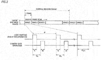
- Fig. 2 is a schematic diagram illustrating the temporal relationship between an operation (light emitting operation) of light emitting unit and an operation (camera gate operation) of a gate when imaging respective target distance ranges.
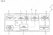
- an obstacle detecting apparatus 1 which is installed in a vehicle V (the own vehicle) includes an image acquiring apparatus 2, an image processing unit (a distance image data generating unit) 3, an object recognition processing unit 4, and a determination unit 10.
- the image acquiring apparatus 2 includes a light emitting unit 5, an objective lens 6, a light intensifying unit 7, a high-speed camera (an image acquisition unit) 8, and a timing controller (a timing control unit) 9.
- the light emitting unit 5 is, for example, a near-infrared LED arranged at a front end part of the vehicle V. As shown in Fig. 2 , the light emitting unit 5 emits pulse light to a predetermined direction (for example, forward from the vehicle V) for a predetermined light emission period tL (for example, 5 ns), according to a pulse signal output from the timing controller 9.
- the light emission cycle tP of pulse light which is radiated from the light emitting unit 5 is set to, for example, an interval of 10 ⁇ s or less.
- the objective lens 6 is, for example, an optical system set so as to have such an angle of field that it is possible to image a predetermined range in front of the vehicle V, and receives reflected light from objects.
- the objective lens 6 may be disposed close to the light emitting unit 5, or may be disposed apart from the light emitting unit.
- the light intensifying unit 7 includes a gate 7a and an image intensifier 7b
- the gate 7a is opened and closed according to an opening/closing command signal from the timing controller 9.
- a period (gate period) tG when the gate 7a is opened is set to 5 ns similarly to the light emission period tL.
- the gate period tG is proportional to the imaging object length (imaging object depth) of each range (target distance range) of an overall imaging range from a range 1 to a range n. As the gate period tG is lengthened, the imaging object length of each range lengthens.
- the imaging object length is obtained from the product of light speed and the gate period tG, and in the present embodiment, since the gate period tG is set to 5 ns, the imaging object length becomes 1.5 m from the product of light speed (about 3 ⁇ 10 8 m/s) and the gate period (5 ns).
- the image intensifier 7b is a device for first converting very weak light (such as reflected light from objects) into electrons, and electrically amplifying them, and converting them back into a fluorescent image, thereby doubling the amount of light, such that it is possible to see an image with clear contrast.
- Light amplified by the image intensifier 7b is guided to an image sensor of the high-speed camera 8.
- the high-speed camera 8 images the image output from the light intensifying unit 7, according to a command signal from the timing controller 9, and outputs the acquired image to the image processing unit 3.
- a camera having a resolution of 640x480 (transverse: longitudinal), luminance values 1 to 255 (256 levels), and a frame rate of 100 fps or more is used.
- the timing controller 9 controls imaging timings by setting a delay time tD (in Fig. 2 , tD n , tD n+1 ) which is a time from when the light emitting unit 5 start to emit light to when the gate 7a is opened such that the timings when images are acquired by the high-speed camera 8 become the timings when reflected light from target distance ranges which are target imaging ranges reach, and outputting opening/closing command signals according to the delay time tD.
- the delay time tD is a value to determine the distance (imaging object distance) from the vehicle V to each target distance range.
- the relationship between the delay time tD and the imaging object distance is obtained from the following Expression (1).
- Imaging Object Distance Light Speed about 3 ⁇ 10 8 m / s ⁇ Delay Time tD / 2
- the timing controller 9 changes the imaging range of the high-speed camera 8 forward from the vehicle V by repeatedly lengthening the delay time tD by a predetermined interval (for example, 10 ns) such that the target distance range continuously goes forward (away) from the vehicle V. Also, the timing controller 9 performs control such that the imaging operation of the high-speed camera 8 starts immediately before the gate 7a is opened and the imaging operation finishes after the gate 7a is completely closed.
- a predetermined interval for example, 10 ns
- the timing controller 9 controls the light emitting unit 5, the gate 7a, and the high-speed camera 8 such that they perform a plurality of times of light emission and exposure for each of preset target distance ranges (each range of the range 1, the range 2, ..., and the range n).
- Light which the high-speed camera 8 has received is converted into electric charge, and a plurality of times of light emission and exposure is repeated, whereby the electric charge is accumulated.
- One image which is acquired in every predetermined charge accumulation period is called a frame.
- the high-speed camera 8 may acquire one image (one frame) with respect to each target distance range, or may acquire a plurality of images (several frames) with respect to each target distance range. In the above-mentioned way, the high-speed camera 8 acquires a plurality of different images of target distance ranges, and outputs the plurality of acquired images to the image processing unit 3.
- the image processing unit 3 generates distance image data representing the distances to objects (subjects) of respective pixels, based on the luminance of the same pixels in all images acquired by the high-speed camera 8, and outputs the generated distance image data to the object recognition processing unit 4.
- the object recognition processing unit 4 specifies objects included in the distance image data.
- a well-known technology such as pattern mapping can be used.
- the determination unit 10 determines the relationship (such as distances and directions) between the vehicle (the vehicle V) and the objects (such as persons, automobiles, and signs) specified by the object recognition processing unit 4.
- the timing controller 9 sets the delay time tD such that the timings when an image which is acquired by the high-speed camera 8 becomes the timing when reflected light from predetermined target distance ranges reaches, thereby controlling imaging timings of the high-speed camera 8.
- the time required for light emitted from the light emitting unit 5 to return from the target distance range becomes the time required for the light to travel out and back over the distance (imaging object distance) between the vehicle V and the target distance range. Therefore, the delay time tD can be obtained from the imaging object distance and the light speed.
- luminance value data of pixels corresponding to the location of the corresponding object and affected by the reflected light represent values higher than luminance value data of the other pixels. Therefore, it is possible to obtain the distance to the object existing in the target distance range, based on the luminance value data of the respective pixels.
- Fig. 3 shows a situation where four objects A to D exist at different locations in front of the vehicle V.
- the object A is a person holding an umbrella
- the object B is a motorcycle on the oncoming lane side
- the object C is a tree on the walkway side
- the object D is a vehicle (an oncoming vehicle) on the oncoming lane side. It is assumed that the relationship of the distances between the vehicle V and the respective objects is A ⁇ B ⁇ C ⁇ D.
- imaging ranges are partially overlapped such that reflected light from one object is reflected in pixels of images of a plurality of continuous imaging ranges.
- the increment in the imaging object distance is set such that imaging ranges change while partially overlapping.
- Fig. 5 shows temporal luminance variations in pixels corresponding to the respective objects.
- the luminance values of the same pixels in the plurality of consecutive images represent features having triangular wave shapes in which the luminance values gradually increase and have peaks at the positions of the respective objects A to D and gradually decrease. That is, since the increment is set such that reflected light from one object is reflected in a plurality of images, the temporal luminance variations in the pixels have the triangular wave shapes. Therefore, if imaging ranges corresponding to the peaks of the triangular wave shapes are set at the distances from the vehicle V to the respective objects (subjects) A to D of the pixels, it is possible to improve detection accuracy.
- the obstacle detecting apparatus 1 having the image acquiring apparatus 2 can be used for light distribution control of a so-called AHB (automatic high beam) system and an ADB (adaptive driving beam) system.
- AHB automatic high beam
- ADB adaptive driving beam
- each light spot in the image acquired by the camera sensor It is possible to obtain the distance of each light spot in the image acquired by the camera sensor from the images acquired by the image acquiring apparatus 2, and from the distance, the luminance, shape (the shape of the light spot and the periphery thereof), time-series variation, and so on of each light spot, it is possible to determine whether the light spot corresponds to a vehicle. That is, by using the image acquiring apparatus 2 and another camera sensor together, it is possible to perform detection of objects, distant vehicles, with high accuracy at high speed, and it is possible to suitably perform light distribution control of an AHB system or an ADB system.
- Fig. 6A is a view illustrating examples of light paths of light which is emitted from the own vehicle and light which is emitted from neighboring vehicles, and light paths of the reflected light of the emitted light.
- Fig. 6B is a timing chart illustrating the relationship between the light emission cycle and imaging timings (exposure cycle) of the own vehicle and the light emission cycle of the neighboring vehicles.
- Fig. 6A in front of the vehicle V (the own vehicle), there are a pedestrian P on the left walkway, an oncoming vehicle VA in the opposing lane, and a lateral vehicle VB coming from the right side. Also, behind the vehicle V, there is a following vehicle VC. If the neighboring vehicles VA to VC have image acquiring systems similar to that of the vehicle V, pulse light emitted from the neighboring vehicles VA and VB, and reflected light which is light emitted from the neighboring vehicles VA to VC and reflected from, for example, the pedestrian P enter from the objective lens 6 of the vehicle V. In this case, as shown in Fig.
- the high-speed camera 8 of the vehicle V continuously and repeatedly images not only light emitted from the light emitting unit 5 but also light emitted from the neighboring vehicles VA to VC.
- the high-speed camera accumulates electric charge in the image sensor by repeating light emission and exposure many times, and images the electric charge. Therefore, if the high-speed camera is repeatedly exposed to light emitted from the neighboring vehicles VA to VC, errors may be in the luminance value data of pixels of acquired images, and it may not be possible to acquire accurate distance information.
- Fig. 7 is a control block diagram of the timing controller 9 according to the example.
- Fig. 8 is a view illustrating modulation control on a light emission cycle and imaging timings according to the example.
- Fig. 9 is a view illustrating modulation control according to another example of the example.
- Fig. 7 first, various conditions such as desired target distance ranges are input. Then, the timing controller 9 performs frame sequence control. In the frame sequence control, for each of target distance ranges (ranges 1 to n), a light emission pulse width, an exposure pulse width, and a light-emission/exposure delay value to determine the light emission period tL of pulse light, the gate period tG, and the delay time tD shown in Fig. 2 are respectively set. Also, the timing controller 9 sets a basic interval period which is a constant time of an interval period which is the light emission cycle tP of pulse light (a time from a pulse light emission start time point to the next pulse light emission start time point), and a random-number interval period.
- the timing controller sets a basic interval period which is a constant time and a random-number interval period, in sync with the light emission cycle of pulse light.
- the random-number interval period is a time which can be changed randomly, for example, according to random numbers which are generated by a random number generator circuit.
- the random number generator circuit may be installed in the timing controller 9, or in an ECU installed in the vehicle and capable of communication with the timing controller 9.
- the timing controller 9 generates a light emission pulse signal and an exposure pulse signal from the light emission pulse width, the exposure pulse width, the light-emission/exposure delay value, the basic interval periods, and the random-number interval periods set as described above.
- the timing controller 9 outputs the generated light emission pulse signal to the light emitting unit 5 while outputting the generated exposure pulse signal to the gate 7a (and the high-speed camera 8).
- the light emitting unit 5 Based on the light emission pulse signal, the light emitting unit 5 emits pulse light with predetermined light emission periods tL in the light emission cycle tP, forward from the vehicle.
- the gate 7a performs opening/closing operations with predetermined gate periods tG at the predetermined imaging timings (in the same cycle as the light emission cycle tP).
- the light emission cycle tP of pulse light and imaging timings sync with the light emission cycle tP are determined based on times obtained by adding random-number interval periods to the basic interval periods. In this way, the light emission cycle tP of the light emitting unit 5 and the gate opening/closing cycle of the gate 7a (imaging timings) are modulated randomly by random numbers.
- the timing controller 9 may be configured to control the light emission cycle tP by setting a part of the basic interval period of the light emission cycle tP to an interval period depending on each target distance range (frame) and adding a random-number interval period thereto.
- a part of the basic interval period is changed to an interval period depending on each frame, whereby basic interval periods for imaging respective ranges become different times. If random-number interval periods are added to different basic interval periods depending on frames, it is possible to more surely prevent the influence of pulse light emitted from the neighboring vehicles VA to VC.
- an obstacle detecting apparatus 101 which is installed in a vehicle V (the own vehicle) includes an image acquiring apparatus 102, an object recognition processing unit 103, and a determination unit 104.
- the image acquiring apparatus 102 includes a light emitting unit 5, an objective lens 6, a light intensifying unit 7, a high-speed camera (an image acquisition unit) 8, a timing controller (a timing control unit) 9, an image processing unit 110.
- the image processing unit 110 generates distance image data representing the distances to objects (subjects) of respective pixels, based on the luminance of the same pixels in images of all imaging ranges acquired by the high-speed camera 8, and outputs the generated distance image data to the object recognition processing unit 103.
- the object recognition processing unit 103 specifies objects included in the distance image data.
- a well-known technology such as pattern mapping can be used.
- the determination unit 104 determines the relationship (such as distances and directions) between the vehicle (the vehicle V) and the objects (such as persons, automobiles, and signs) specified by the object recognition processing unit 103.
- Fig. 6A of the first example in front of the vehicle V (the own vehicle), there are a pedestrian P on the left walkway, an oncoming vehicle VA in the opposing lane, and a lateral vehicle VB coming from the right side. Also, behind the vehicle V, there is a following vehicle VC. If the neighboring vehicles VA to VC have distance image data generating systems similar to that of the vehicle V, pulse light emitted from the neighboring vehicles VA and VB, and irregular reflected light which is light emitted from the neighboring vehicles VA to VC and reflected from, for example, the pedestrian P enter from the objective lens 6 of the vehicle V.
- the obstacle detecting apparatus emits pulse light from the light emitting unit 5 of the vehicle V which is the own vehicle, and acquires images of the ranges 1 to n while changing the delay time tD, and compares the luminance value data of the same pixels in the respective images, and detects the highest luminance value data as the distances of the corresponding pixels. Therefore, if irregular reflected light is included in images, errors may be in the luminance value data of the respective pixels of the images, and it may not be possible to acquire accurate distance information.
- the light emission cycles of the neighboring vehicles are the same as the exposure cycle of the vehicle V (the opening cycle of the gate 7a) as shown in Fig. 6B , since the high-speed camera 8 of the vehicle V is continuously and repeatedly exposed not only to light emitted from the light emitting unit 5 but also to light emitted from the neighboring vehicles VA to VC, it is likely that distance information cannot be accurately acquired.
- FIG. 11 (a) and (b) are schematic diagrams illustrating the irradiation area of light from the light emitting unit 5 of the vehicle V according to the second example, the imaging area of the high-speed camera 8 of the vehicle V, the irradiation area of light from the light emitting unit of the oncoming vehicle VA, and images acquired by the high-speed camera 8 of the vehicle V. Also, (c) of Fig. 11 shows an image obtained by removing noise from the acquired images shown in (a) and (b) of Fig. 11 and combining the images.
- FIG. 11 (a) shows an irradiation area VR of pulse light which is emitted from the light emitting unit 5 of the vehicle V at a first timing, the imaging area S of the high-speed camera 8 of the vehicle V, an irradiation area VAF of light which is emitted from the light emitting unit of the oncoming vehicle VA, and the pedestrian P on the walkway on the right side as seen from the vehicle V.
- Fig. 11 shows an irradiation area VR of pulse light which is emitted from the light emitting unit 5 of the vehicle V at a first timing, the imaging area S of the high-speed camera 8 of the vehicle V, an irradiation area VAF of light which is emitted from the light emitting unit of the oncoming vehicle VA, and the pedestrian P on the walkway on the right side as seen from the vehicle V.
- (b) shows an irradiation area VL of pulse light which is emitted from the light emitting unit 5 of the vehicle V at a second timing different from the first timing, the imaging area S of the high-speed camera 8 of the vehicle V, an irradiation area VAR of light which is emitted from the light emitting unit of the oncoming vehicle VA, and the pedestrian P on the right walkway.
- the light emitting unit 5 can emit pulse light to a plurality of directions of the area in front of the vehicle, for example, toward the right side (a first direction) and left side (a second direction) in front of the vehicle, shown by the irradiation area VR and the irradiation area VL, at different timings, respectively.
- the light emitting unit 5 are mounted in the left and right head lamps of the vehicle V, respectively, and are configured such that the light emitting unit 5 mounted in the right head lamp irradiates the irradiation area VR and the light emitting unit 5 mounted in the left head lamp irradiates the irradiation area VL.
- a single light emitting unit capable of switching between the irradiation areas may be provided on the front end part of the vehicle V and switch between the irradiation areas VR and VL of pulse light from the single light emitting unit at the first and second timings.
- the imaging area S of the high-speed camera 8 of the vehicle V includes areas of the irradiation areas VR and VL of the light emitting unit 5, included in an area in front of the vehicle V. Also, a part of the irradiation area VAF from light emitting unit VA5 (left and right head lamps) of the oncoming vehicle VA overlaps the imaging area S of the high-speed camera 8 of the vehicle V.
- the timing controller 9 outputs a pulse signal to the light emitting unit 5 such that pulse light is emitted toward the right side (the irradiation area VR) in front of the vehicle at the first timing shown in (a) of Fig. 11 .
- the timing controller 9 outputs an opening/closing command signal to the gate 7a while outputting a command signal to the high-speed camera 8 such that the high-speed camera images the reflected light of the pulse light radiated to the irradiation area VR at the first timing (a first imaging step).
- the timing controller 9 outputs a pulse signal to the light emitting unit 5 such that pulse light is emitted toward the left side (the irradiation area VL) at the second timing shown in (b) of Fig. 11 .
- the timing controller 9 outputs an opening/closing command signal to the gate 7a while outputting a command signal to the high-speed camera 8 such that the high-speed camera images the reflected light of the pulse light radiated to the irradiation area VL at the second timing (a second imaging step).
- the timing controller 9 controls the operations of the light emitting unit 5, the gate 7a, and the high-speed camera 8 such that the irradiation areas VR and VL of pulse light are switched and imaged at the first and second timings.
- the high-speed camera 8 acquires an image (a first image) 1a shown in (a) of Fig. 11 , at the first timing, and acquires an image (a second image) 1b shown in (b) of Fig. 11 , at the second timing.
- the second image 1b of (b) of Fig. 11 does not include an image of the pedestrian P since the pedestrian P is not included in the irradiation area VL from the vehicle V, and includes only an image of the light VAL emitted from the light emitting unit VA5 of the oncoming vehicle VA.
- the high-speed camera 8 outputs the first image Ia and the second image Ib to the image processing unit 110.
- the image processing unit 110 compares the first image Ia and the second image Ib, and distinguishes between the reflected light of the light emitted from the vehicle V and the other light. In other words, the image processing unit 110 determines that the light VAL emitted from the light emitting unit VA5 and included in an area which the light emitting unit 5 are not irradiating in (b) of Fig. 11 (an area corresponding to the irradiation area VR of (a) of Fig. 11 ) is not reflected light of the light emitted from the light emitting unit 5 of the vehicle V.
- the image processing unit 110 removes the light VAL as noise, i.e.
- the composite image Ic does not include an image of the light VAL emitted from the oncoming vehicle VA.
- the light emitting unit 5 can emit pulse light toward a plurality of directions (for example, the right side and left side in front of the vehicle).
- the timing controller 9 controls the light emission cycle of pulse light and imaging timings such that at the first timing, pulse light is emitted toward the right side and the reflected light of the emitted pulse light is imaged, and at the second timing, pulse light is emitted toward the left side and the reflected light of the emitted pulse light is imaged.
- the image processing unit 110 compares the first image Ia acquired at the first timing and the second image Ib acquired at the second timing, and determines whether light other than the reflected light of the light emitted from the vehicle V is imaged.
- the image processing unit removes the corresponding light (for example, the light VAL) as noise, and combines the first image 1a and the second image 1b, thereby generating the composite image 1c. According to this configuration, it is possible to acquire accurate distance information on objects in front of the vehicle without being affected by irregular reflected light and pulse light emitted from a neighboring vehicle.
- the corresponding light for example, the light VAL
- the light emitting unit 5 can emit pulse light toward the right side and left side in front of the vehicle; however, this disclosure is not limited thereto.
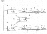
- (a) of Fig. 12 shows, as a third example, an irradiation area VU of pulse light which is emitted from the light emitting unit 5 of the vehicle V at a first timing, the imaging area S of the high-speed camera 8 of the vehicle V, an irradiation area VAF of light which is emitted from the light emitting unit of the oncoming vehicle VA, and the pedestrian P on the walkway on the left side as seen from the vehicle V.
- the 12 shows an irradiation area VD of pulse light which is emitted from the light emitting unit 5 of the vehicle V at a second timing different from the first timing, the imaging area S of the high-speed camera 8 of the vehicle V, an irradiation area VAR of light which is emitted from the light emitting unit of the oncoming vehicle VA, and the pedestrian P on the left walkway.
- the irradiation area VU of pulse light which is emitted at the first timing is the upper irradiation area in front of the vehicle V
- the irradiation area VD of pulse light which is emitted at the second timing is the lower irradiation area of the area in front of the vehicle V.
- the light emitting unit 5 can be configured to emit pulse light toward each of the upper side and lower side in front of the vehicle V. Also, even in the second example, the light emitting unit 5 may be mounted in the left and right head lamps, or a single light emitting unit capable of switching between the irradiation areas may be configured.
- the timing controller 9 outputs a pulse signal to the light emitting unit 5 such that, at the first timing shown in (a) of Fig. 12 , pulse light is emitted toward the upper side (the irradiation area VU) in front of the vehicle, and at the second timing shown in (b) of Fig. 11 , pulse light is emitted toward the lower side (the irradiation area VD). Also, the timing controller 9 outputs an opening/closing command signal to the gate 7a while outputting a command signal to the high-speed camera 8, such that the reflected light of pulse light is imaged at each of the first timing and the second timing.
- the timing controller 9 controls the operations of the light emitting unit 5, the gate 7a, and the high-speed camera 8.
- the image processing unit 110 acquires an image Id acquired at the first timing shown in (a) of Fig. 1 , and an image Ie acquired at the second timing shown in (b) of Fig. 11 .
- the image Id of (a) of Fig. 12 includes an image of reflected light PU from the upper body of the pedestrian P included in the irradiation area VU from the vehicle V, and an image of the light VAL emitted from the light emitting unit VA5 of the oncoming vehicle VA to the irradiation area VAF partially overlapping the imaging area S of the high-speed camera 8.
- the image Ie of (b) of Fig. 12 includes an image of reflected light PD from the lower body of the pedestrian P (and images of reflected light from lane marks on the road) included in the irradiation area VD from the vehicle V, and an image of the light VAL emitted from the light emitting unit VA5 of the oncoming vehicle VA.
- the image processing unit 110 compares the image Id and the image Ie, and distinguishes between the reflected light of the light emitted from the vehicle V and the other light. In other words, the image processing unit 110 determines that the light VAL emitted from the light emitting unit VA5 and included in an area which the light emitting unit 5 is not irradiating in (b) of Fig.
- the image processing unit 110 removes the light VAL as noise, i.e. sets 0 as the luminance values of pixels of the data corresponding to the light VAL, and generates a composite image If (see (c) of Fig. 12 ) by composing the image Id and the image Ie. As shown in (c) of Fig. 12 , the composite image If does not include an image of the light VAL emitted from the oncoming vehicle VA.
- the obstacle detecting apparatus emits pulse light from the light emitting unit 5 toward the upper side and lower side in front of the vehicle at different timings, and compares the image Id and the image Ie, and removes light other than the reflected light of the light emitted from the vehicle V, as noise, and generates the composite image If. Therefore, it is possible to acquire accurate distance information without being affected by irregular reflected light and pulse light which is emitted from neighboring vehicles.
- the timing controller 9 controls the light emission cycle tP of the light emitting unit 5 such that the light emission cycle tP is modulated by random numbers; however, this disclosure is not limited to this example.
- the timing controller may be configured to control the light emission cycle and imaging timings of the vehicle by communicating with a neighboring vehicle such that the light emission cycle and imaging timings of the vehicle are not the same as the light emission cycles of pulse light which is emitted from the neighboring vehicle.
- the timing controller modulates the light emission cycle and imaging timings of the vehicle such that they are different from the light emission cycles of the neighboring vehicle. In this way, the light emission cycle and imaging timings of pulse light of the vehicle are controlled. Therefore, it is possible to acquire accurate distance information unaffected by light from a neighboring vehicle.
- the timing controller may be configured to control the light emission cycle and imaging timings based on the direction and location of the vehicle.
- each light emission cycle including a basic interval period and a random-number interval period according to the direction and location of the vehicle, it is possible to control the light emission cycle and imaging timings of the vehicle such that they are not the same as the light emission cycles of pulse light from a neighboring vehicle different from the vehicle in their directions and locations.
- direction information on the direction in which the vehicle is moving can be acquired by, for example, a geometric sensor mounted on the vehicle, and information on the location of the vehicle can be acquired, for example, from a navigation system mounted on the vehicle and having map data and GPS (Global Positioning System) data.
- GPS Global Positioning System
- the imaging object length, the amount of change in the imaging object distance, the number of frames for each target distance range, and so on can be appropriately set according to the performance of the high-speed camera 8 and the image processing unit 3 (the image processing unit 110),
- the high-speed camera 8 functions as an image acquisition unit; however, this disclosure is not limited to this example.
- the image processing unit 3 (the image processing unit 110) may have the function of an image acquisition unit, or a separate memory for storing images may be provided as an image acquisition unit between the high-speed camera 8 and the image processing unit 3 (the image processing unit 110).
- the light intensifying unit 7 (the gate 7a and the image intensifier 7b) is installed between the objective lens 6 and the high-speed camera 8; however, this disclosure is not limited to this example.
- the light intensifying unit 7 it is possible to acquire a plurality of images by performing gating in the high-speed camera 8 at predetermined imaging timings.
- object recognition is performed by generating distance image data by the image processing unit 3; however, objects may be recognized from images of respective target distances acquired by the high-speed camera 8.
Landscapes
- Physics & Mathematics (AREA)
- Engineering & Computer Science (AREA)
- Electromagnetism (AREA)
- Computer Networks & Wireless Communication (AREA)
- General Physics & Mathematics (AREA)
- Radar, Positioning & Navigation (AREA)
- Remote Sensing (AREA)
- Mechanical Engineering (AREA)
- Optical Radar Systems And Details Thereof (AREA)
- Traffic Control Systems (AREA)
- Studio Devices (AREA)
Abstract
Description
- This disclosure relates to an image acquiring apparatus for a vehicle, a control device, a vehicle having the image acquiring apparatus for a vehicle or the control device, and an image acquiring method for a vehicle.
-
Patent Document 1 discloses a distance image data generating apparatus for a vehicle, which emits pulse light forward from a vehicle having the distance image data generating apparatus in a predetermined cycle and images reflected light from target distances at imaging timings set according to the target distances, thereby acquiring a plurality of different images of the target distances, and generates distance image data representing the distance to an object of each pixel, based on the luminance of the same pixel in the images. - Patent Document 1:
JP-A-2009-257983 - The distance image data generating apparatus for a vehicle disclosed in
Patent Document 1 acquires an image of each predetermined target distance range by imaging reflected light of pulse light when a predetermined time elapses after light emission of pulse light from the vehicle. This apparatus accumulates electric charge for images by repeating light emission of pulse light and exposure many times and images the electric charge. Therefore, if the apparatus continuously and repeatedly images pulse light from a neighboring vehicle having the same system, or the reflected light thereof, it may generate erroneous distance image data. - Also, if the device images irregular reflected light from pedestrians, guardrails, and so on and pulse light emitted from neighboring vehicles, it may not be able to acquire accurate distance image data.
- Accordingly, an object of this disclosure is to provide an image acquiring apparatus for a vehicle, a control device, a vehicle having the image acquiring apparatus for a vehicle or the control device, and an image acquiring method for a vehicle, capable of acquiring accurate distance information without being affected by light emission of pulse light from a neighboring vehicle and irregular reflected light.
- In order to achieve the above-mentioned object, an image acquiring apparatus for a vehicle according to this disclosure includes:
- a light emitting unit configured to emit pulse light to a predetermined direction; an image acquisition unit configured to acquire a plurality of different images of target distance ranges by imaging reflected light returning from the target distance ranges at imaging timings set according to the target distance ranges; and
- a timing control unit configured to control a light emission cycle of the pulse light and the imaging timings,
- wherein the timing control unit is configured to control the light emission cycle and the imaging timings such that the light emission cycle and the imaging timings are modulated by random numbers.
- According to the above-mentioned configuration, the image acquiring apparatus for a vehicle can acquire accurate distance information without being affected by pulse light emission from a neighboring vehicle.
- The timing control unit may be configured to modulate the light emission cycle and the imaging timings by adding a time generated randomly to each of a basic interval period of the light emission cycle and a basic interval period of the imaging timings.
- According to the above-mentioned configuration, it is possible to modulate the light emission cycle and imaging timings by a simple configuration.
- The timing control unit may be configured to modulate the light emission cycle and the imaging timings by modulating a part of the basic interval period by random numbers for each of the target distance ranges.
- According to the above-mentioned configuration, it is possible to more surely prevent the effect of pulse light from a neighboring vehicle.
- Also, in order to achieve the above-mentioned object, an image acquiring apparatus for a vehicles according to this disclosure includes:
- a light emitting unit configured to emit pulse light to a predetermined direction;
- an image acquisition unit configured to acquire a plurality of different images of target distance ranges by imaging reflected light returning from the target distance ranges at imaging timings set according to the target distance ranges; and
- a timing control unit configured to control a light emission cycle of the pulse light and the imaging timings,
- wherein the timing control unit is configured to control the light emission cycle and the imaging timings by communicating with a neighboring vehicle such that the light emission cycle and the imaging timings are not the same as a light emission cycle of pulse light which is emitted from the neighboring vehicle.
- Also, in order to achieve the above-mentioned object, an image acquiring apparatus for a vehicles according to this disclosure includes:
- a light emitting unit configured to emit pulse light to a predetermined direction;
- an image acquisition unit configured to acquire a plurality of different images of target distance ranges by imaging reflected light returning from the target distance ranges at imaging timings set according to the target distance ranges; and
- a timing control unit configured to control a light emission cycle of the pulse light and the imaging timings,
- wherein the timing control unit is configured to control the light emission cycle and the imaging timings based on a direction and a location of the own vehicle.
- According to these configurations, the image acquiring apparatus can acquire accurate distance information without being affected by pulse light emission from a neighboring vehicle.
- The direction of the own vehicle may be determined by a geometric sensor, and the location of the own vehicle may be determined based on GPS data.
- According to the above-mentioned configuration, it is possible to easily determine the direction and location of the vehicle, and suitably control the light emission cycle and imaging timings.
- Also, in order to achieve the above-mentioned object, a control device of this disclosure is a control device for controlling an image acquiring apparatus for a vehicle which includes a light emitting unit configured to emit pulse light to a predetermined direction, and an image acquisition unit configured to acquire a plurality of different images of target distance ranges by imaging reflected light returning from the target distance ranges at imaging timings set according to the target distance ranges, and is configured to control a light emission cycle of the pulse light and the imaging timings such that the light emission cycle and the imaging timings are modulated by random numbers.
- According to the above-mentioned configuration, the control device can acquire accurate distance information without being affected by pulse light emission from a neighboring vehicle.
- Also, in order to achieve the above-mentioned object, an image acquiring method for a vehicle according to this disclosure is an image acquiring method for a vehicle which acquires a plurality of different images of target distance ranges by imaging reflected light of pulse light emitted to a predetermined direction while changing imaging timings, and includes controlling a light emission cycle of the pulse light and the imaging timings such that the light emission cycle and the imaging timings are modulated by random numbers.
- According to the above-mentioned method, it is possible to provide an image acquiring method for a vehicle capable of acquiring accurate distance information without being affected by pulse light emission from a neighboring vehicle.
- In order to achieve the above-mentioned object, an image acquiring apparatus for a vehicle according to this disclosure includes:
- a light emitting unit configured to emit pulse light to a predetermined direction;
- an image acquisition unit configured to acquire a plurality of different images of target distance ranges by imaging reflected light returning from the target distance ranges at imaging timings set according to the target distance ranges;
- a timing control unit configured to control a light emission cycle of the pulse light and the imaging timings; and
- an image processing unit configured to perform image processing on the plurality of images acquired by the image acquisition unit,
- wherein the light emitting unit is configured to emit the pulse light toward a plurality of directions,
- wherein the timing control unit is configured to control the light emission cycle of pulse light and the imaging timings such that at a first timing, the pulse light is emitted toward a first direction of the plurality of directions and reflected light of the emitted pulse light is imaged, and at a second timing different from the first timing, the pulse light is emitted toward a second direction different from the first direction and reflected light of the emitted pulse light is imaged, and
- wherein the image processing unit is configured to compare a first image acquired at the first timing and a second image acquired at the second timing to determine whether light other than the reflected light is imaged, and generate a composite image of the first image and the second image in which light other than the reflected light is removed as noise if it is determined that light other than the reflected light is imaged.
- According to the above-mentioned configuration, it is possible to acquire accurate distance information without being affected by irregular reflected light and pulse light which is emitted from a neighboring vehicle.
- The first direction may be a direction to a right area in front of an own vehicle having the image acquiring apparatus, and the second direction may be a direction to a left area in front of the own vehicle.
- The first direction may be a direction to an upper area in front of the own vehicle, and the second direction may be a direction to a lower area in front of the own vehicle.
- According to these configurations, for example, it is possible to easily acquire accurate distance information.
- Also, in order to achieve the above-mentioned object, a control device of this disclosure is a control device for controlling an image acquiring apparatus for a vehicle which includes a light emitting unit configured to emit pulse light to a plurality of directions, and an image acquisition unit configured to acquire a plurality of different images of target distance ranges by imaging reflected light returning from the target distance ranges at imaging timings set according to the target distance ranges, and includes:
- a timing control unit configured to control a light emission cycle of the pulse light and the imaging timings; and
- an image processing unit configured to perform image processing on the plurality of images acquired by the image acquisition unit,
- wherein the timing control unit is configured to control the light emission cycle of pulse light and the imaging timings such that at a first timing, the pulse light is emitted toward a first direction of the plurality of directions and reflected light of the emitted pulse light is imaged, and at a second timing different from the first timing, the pulse light is emitted toward a second direction different from the first direction and reflected light of the emitted pulse light is imaged, and
- wherein the image processing unit is configured to compare a first image acquired at the first timing and a second image acquired at the second timing to determine whether light other than the reflected light is imaged, and generate a composite image of the first image and the second image in which light other than the reflected light is removed as noise if it is determined that light other than the reflected light is imaged.
- According to the above-mentioned configuration, it is possible to acquire accurate distance information without being affected by irregular reflected light and pulse light which is emitted from a neighboring vehicle.
- Also, in order to achieve the above-mentioned object, an image acquiring method for a vehicle according to this disclosure is an image acquiring method for a vehicle which acquires a plurality of different images of target distance ranges by imaging reflected light of pulse light emitted to predetermined directions while changing imaging timings and includes:
- a first imaging step of emitting the pulse light toward a first direction which is one of the predetermined directions and imaging reflected light of the pulse light at a first timing;
- a second imaging step of emitting the pulse light toward a second direction different from the first direction and imaging reflected light of the pulse light at a second timing different from the first timing; and
- an image composing step of comparing a first image acquired in the first imaging step and a second image acquired in the second imaging step to determine whether light other than the reflected light is imaged and generating a composite image of the first image and the second image by removing light other than the reflected light as noise if it is determined that light other than reflected light is imaged.
- According to the above-mentioned method, it is possible to acquire accurate distance information without being affected by irregular reflected light and pulse light which is emitted from a neighboring vehicle.
- Also, in order to achieve the above-mentioned object, a vehicle of this disclosure includes the image acquiring apparatus described above or the control devices described above.
- According to the above-mentioned configuration, it is possible to improve safety of a vehicle having, for example, a self-driving system.
- According to this disclosure, it is possible to provide an image acquiring apparatus for a vehicle, a control device, a vehicle having the image acquiring apparatus for a vehicle or the control device, and an image acquiring method for a vehicle, capable of acquiring accurate distance information without being affected by light emission of pulse light from a neighboring vehicle and irregular reflected light.
-
-
Fig. 1 is a block diagram illustrating the configuration of an obstacle detecting apparatus of an embodiment. -
Fig. 2 is a view illustrating the temporal relationship between an operation (light emitting operation) of light emitting unit and an operation (camera gate operation) of a gate when imaging target distance ranges. -
Fig. 3 is a view illustrating a situation where four different objects exist at different positions in front of the own vehicle. -
Fig. 4 is a view illustrating a state where imaging ranges partially overlap. -
Fig. 5 is a schematic diagram illustrating temporal luminance variations in pixels corresponding to the respective objects. -
Fig. 6A is a view illustrating examples of light paths of light which is emitted from the own vehicle and light which is emitted from neighboring vehicles, and light paths of the reflected light of the emitted light. -
Fig. 6B is a timing chart illustrating the relationship between the light emission cycle and imaging timings (exposure cycle) of the own vehicle and the light emission cycle of the neighboring vehicles. -
Fig. 7 is a control block diagram of a timing control unit according to a first example. -
Fig. 8 is a view illustrating modulation control on a light emission cycle and imaging timings according to the first example. -
Fig. 9 is a view illustrating modulation control according to another example of the first example. -
Fig. 10 is a block diagram illustrating the configuration of an obstacle detecting apparatus according to a second example. -
Fig. 11 is a schematic diagram illustrating the irradiation ranges of light from lamps of an own vehicle according to the second example, the imaging range of a camera of the own vehicle, the irradiation range of light from an oncoming vehicle, and images which are acquired by the camera of the own vehicle. -
Fig. 12 is a schematic diagram illustrating the irradiation ranges of light from lamps of an own vehicle according to a third example, the imaging range of a camera of the own vehicle, the irradiation range of light from an oncoming vehicle, and images which are acquired by the camera of the own vehicle. - Hereinafter, an example of an embodiment will be described in detail with reference to the drawings.
-
Fig. 1 is a block diagram illustrating the configuration of an obstacle detecting apparatus according to the present embodiment using an image acquiring apparatus for a vehicle.Fig. 2 is a schematic diagram illustrating the temporal relationship between an operation (light emitting operation) of light emitting unit and an operation (camera gate operation) of a gate when imaging respective target distance ranges. - As shown in
Fig. 1 , anobstacle detecting apparatus 1 which is installed in a vehicle V (the own vehicle) includes animage acquiring apparatus 2, an image processing unit (a distance image data generating unit) 3, an object recognition processing unit 4, and adetermination unit 10. - The
image acquiring apparatus 2 includes alight emitting unit 5, an objective lens 6, a light intensifying unit 7, a high-speed camera (an image acquisition unit) 8, and a timing controller (a timing control unit) 9. - The
light emitting unit 5 is, for example, a near-infrared LED arranged at a front end part of the vehicle V. As shown inFig. 2 , thelight emitting unit 5 emits pulse light to a predetermined direction (for example, forward from the vehicle V) for a predetermined light emission period tL (for example, 5 ns), according to a pulse signal output from the timing controller 9. The light emission cycle tP of pulse light which is radiated from thelight emitting unit 5 is set to, for example, an interval of 10 µs or less. - The objective lens 6 is, for example, an optical system set so as to have such an angle of field that it is possible to image a predetermined range in front of the vehicle V, and receives reflected light from objects. The objective lens 6 may be disposed close to the
light emitting unit 5, or may be disposed apart from the light emitting unit. - The light intensifying unit 7 includes a
gate 7a and animage intensifier 7b - The
gate 7a is opened and closed according to an opening/closing command signal from the timing controller 9. In the present embodiment, a period (gate period) tG when thegate 7a is opened is set to 5 ns similarly to the light emission period tL. The gate period tG is proportional to the imaging object length (imaging object depth) of each range (target distance range) of an overall imaging range from arange 1 to a range n. As the gate period tG is lengthened, the imaging object length of each range lengthens. The imaging object length is obtained from the product of light speed and the gate period tG, and in the present embodiment, since the gate period tG is set to 5 ns, the imaging object length becomes 1.5 m from the product of light speed (about 3×10⁸ m/s) and the gate period (5 ns). - The
image intensifier 7b is a device for first converting very weak light (such as reflected light from objects) into electrons, and electrically amplifying them, and converting them back into a fluorescent image, thereby doubling the amount of light, such that it is possible to see an image with clear contrast. Light amplified by theimage intensifier 7b is guided to an image sensor of the high-speed camera 8. - The high-
speed camera 8 images the image output from the light intensifying unit 7, according to a command signal from the timing controller 9, and outputs the acquired image to theimage processing unit 3. In the present embodiment, a camera having a resolution of 640x480 (transverse: longitudinal),luminance values 1 to 255 (256 levels), and a frame rate of 100 fps or more is used. - The timing controller 9 controls imaging timings by setting a delay time tD (in
Fig. 2 , tDn, tDn+1) which is a time from when thelight emitting unit 5 start to emit light to when thegate 7a is opened such that the timings when images are acquired by the high-speed camera 8 become the timings when reflected light from target distance ranges which are target imaging ranges reach, and outputting opening/closing command signals according to the delay time tD. In other words, the delay time tD is a value to determine the distance (imaging object distance) from the vehicle V to each target distance range. The relationship between the delay time tD and the imaging object distance is obtained from the following Expression (1).
- The timing controller 9 changes the imaging range of the high-
speed camera 8 forward from the vehicle V by repeatedly lengthening the delay time tD by a predetermined interval (for example, 10 ns) such that the target distance range continuously goes forward (away) from the vehicle V. Also, the timing controller 9 performs control such that the imaging operation of the high-speed camera 8 starts immediately before thegate 7a is opened and the imaging operation finishes after thegate 7a is completely closed. - The timing controller 9 controls the
light emitting unit 5, thegate 7a, and the high-speed camera 8 such that they perform a plurality of times of light emission and exposure for each of preset target distance ranges (each range of therange 1, therange 2, ..., and the range n). Light which the high-speed camera 8 has received is converted into electric charge, and a plurality of times of light emission and exposure is repeated, whereby the electric charge is accumulated. One image which is acquired in every predetermined charge accumulation period is called a frame. However, the high-speed camera 8 may acquire one image (one frame) with respect to each target distance range, or may acquire a plurality of images (several frames) with respect to each target distance range. In the above-mentioned way, the high-speed camera 8 acquires a plurality of different images of target distance ranges, and outputs the plurality of acquired images to theimage processing unit 3. - The
image processing unit 3 generates distance image data representing the distances to objects (subjects) of respective pixels, based on the luminance of the same pixels in all images acquired by the high-speed camera 8, and outputs the generated distance image data to the object recognition processing unit 4. - The object recognition processing unit 4 specifies objects included in the distance image data. As the object specifying method, a well-known technology such as pattern mapping can be used.
- The
determination unit 10 determines the relationship (such as distances and directions) between the vehicle (the vehicle V) and the objects (such as persons, automobiles, and signs) specified by the object recognition processing unit 4. - Next, an image acquiring operation according to the present embodiment will be described.
- The timing controller 9 sets the delay time tD such that the timings when an image which is acquired by the high-
speed camera 8 becomes the timing when reflected light from predetermined target distance ranges reaches, thereby controlling imaging timings of the high-speed camera 8. In the case where there is any object in a target distance range, the time required for light emitted from thelight emitting unit 5 to return from the target distance range becomes the time required for the light to travel out and back over the distance (imaging object distance) between the vehicle V and the target distance range. Therefore, the delay time tD can be obtained from the imaging object distance and the light speed. - In an image of the high-
speed camera 8 acquired by the above-mentioned method, in the case where there is an object in a target distance range, luminance value data of pixels corresponding to the location of the corresponding object and affected by the reflected light represent values higher than luminance value data of the other pixels. Therefore, it is possible to obtain the distance to the object existing in the target distance range, based on the luminance value data of the respective pixels. -
Fig. 3 shows a situation where four objects A to D exist at different locations in front of the vehicle V. The object A is a person holding an umbrella, and the object B is a motorcycle on the oncoming lane side, and the object C is a tree on the walkway side, and the object D is a vehicle (an oncoming vehicle) on the oncoming lane side. It is assumed that the relationship of the distances between the vehicle V and the respective objects is A < B < C < D. - In this case, in the present embodiment, imaging ranges are partially overlapped such that reflected light from one object is reflected in pixels of images of a plurality of continuous imaging ranges. In other words, as shown in
Fig. 4 , in the case of acquiring images while continuously changing the imaging object distance in the order of B1 , B2, B3, ..., by setting the increment (B2 - B1) in the imaging object distance, shorter than the imaging object length A of each imaging range, the increment in the imaging object distance is set such that imaging ranges change while partially overlapping. -
Fig. 5 shows temporal luminance variations in pixels corresponding to the respective objects. - Since the imaging ranges are partially overlapped, as shown in
Fig. 5 , the luminance values of the same pixels in the plurality of consecutive images represent features having triangular wave shapes in which the luminance values gradually increase and have peaks at the positions of the respective objects A to D and gradually decrease. That is, since the increment is set such that reflected light from one object is reflected in a plurality of images, the temporal luminance variations in the pixels have the triangular wave shapes. Therefore, if imaging ranges corresponding to the peaks of the triangular wave shapes are set at the distances from the vehicle V to the respective objects (subjects) A to D of the pixels, it is possible to improve detection accuracy. - Also, the
obstacle detecting apparatus 1 having theimage acquiring apparatus 2 according to the above-described embodiment can be used for light distribution control of a so-called AHB (automatic high beam) system and an ADB (adaptive driving beam) system. By using theobstacle detecting apparatus 1 together with another camera sensor mounted on the vehicle V, for example, existence or non-existence of objects in front of the vehicle V and the distances to objects are detected from a plurality of different images of target distance ranges acquired by theimage acquiring apparatus 2, and an image of an area in front of the vehicle V is acquired by the another camera sensor. It is possible to obtain the distance of each light spot in the image acquired by the camera sensor from the images acquired by theimage acquiring apparatus 2, and from the distance, the luminance, shape (the shape of the light spot and the periphery thereof), time-series variation, and so on of each light spot, it is possible to determine whether the light spot corresponds to a vehicle. That is, by using theimage acquiring apparatus 2 and another camera sensor together, it is possible to perform detection of objects, distant vehicles, with high accuracy at high speed, and it is possible to suitably perform light distribution control of an AHB system or an ADB system. -
Fig. 6A is a view illustrating examples of light paths of light which is emitted from the own vehicle and light which is emitted from neighboring vehicles, and light paths of the reflected light of the emitted light.Fig. 6B is a timing chart illustrating the relationship between the light emission cycle and imaging timings (exposure cycle) of the own vehicle and the light emission cycle of the neighboring vehicles. - As shown in
Fig. 6A , in front of the vehicle V (the own vehicle), there are a pedestrian P on the left walkway, an oncoming vehicle VA in the opposing lane, and a lateral vehicle VB coming from the right side. Also, behind the vehicle V, there is a following vehicle VC. If the neighboring vehicles VA to VC have image acquiring systems similar to that of the vehicle V, pulse light emitted from the neighboring vehicles VA and VB, and reflected light which is light emitted from the neighboring vehicles VA to VC and reflected from, for example, the pedestrian P enter from the objective lens 6 of the vehicle V. In this case, as shown inFig. 6B , if light emission from the neighboring vehicles is performed at the same timings as the timings of exposure operations (opening operations of thegate 7a) of the vehicle V, the high-speed camera 8 of the vehicle V continuously and repeatedly images not only light emitted from thelight emitting unit 5 but also light emitted from the neighboring vehicles VA to VC. When acquiring images, the high-speed camera accumulates electric charge in the image sensor by repeating light emission and exposure many times, and images the electric charge. Therefore, if the high-speed camera is repeatedly exposed to light emitted from the neighboring vehicles VA to VC, errors may be in the luminance value data of pixels of acquired images, and it may not be possible to acquire accurate distance information. - For this reason, from a comprehensive perspective on the above-described circumstances, the inventors of this application have found a method capable of acquiring accurate distance information without being affected by light emission of pulse light of a neighboring vehicle. Hereinafter, as a method for acquiring accurate distance information, a first example will be described in detail.
-
Fig. 7 is a control block diagram of the timing controller 9 according to the example.Fig. 8 is a view illustrating modulation control on a light emission cycle and imaging timings according to the example.Fig. 9 is a view illustrating modulation control according to another example of the example. - In
Fig. 7 , first, various conditions such as desired target distance ranges are input. Then, the timing controller 9 performs frame sequence control. In the frame sequence control, for each of target distance ranges (ranges 1 to n), a light emission pulse width, an exposure pulse width, and a light-emission/exposure delay value to determine the light emission period tL of pulse light, the gate period tG, and the delay time tD shown inFig. 2 are respectively set. Also, the timing controller 9 sets a basic interval period which is a constant time of an interval period which is the light emission cycle tP of pulse light (a time from a pulse light emission start time point to the next pulse light emission start time point), and a random-number interval period. Similarly, with respect to the opening/closing cycle of thegate 7a (imaging timings), the timing controller sets a basic interval period which is a constant time and a random-number interval period, in sync with the light emission cycle of pulse light. The random-number interval period is a time which can be changed randomly, for example, according to random numbers which are generated by a random number generator circuit. The random number generator circuit may be installed in the timing controller 9, or in an ECU installed in the vehicle and capable of communication with the timing controller 9. - The timing controller 9 generates a light emission pulse signal and an exposure pulse signal from the light emission pulse width, the exposure pulse width, the light-emission/exposure delay value, the basic interval periods, and the random-number interval periods set as described above. The timing controller 9 outputs the generated light emission pulse signal to the
light emitting unit 5 while outputting the generated exposure pulse signal to thegate 7a (and the high-speed camera 8). Based on the light emission pulse signal, thelight emitting unit 5 emits pulse light with predetermined light emission periods tL in the light emission cycle tP, forward from the vehicle. Also, based on the exposure pulse signal, thegate 7a performs opening/closing operations with predetermined gate periods tG at the predetermined imaging timings (in the same cycle as the light emission cycle tP). - In this case, in the present embodiment, as shown in
Fig. 8 , the light emission cycle tP of pulse light and imaging timings sync with the light emission cycle tP are determined based on times obtained by adding random-number interval periods to the basic interval periods. In this way, the light emission cycle tP of thelight emitting unit 5 and the gate opening/closing cycle of thegate 7a (imaging timings) are modulated randomly by random numbers. - According to the
image acquiring apparatus 2 of the example described above, the following effects are obtained. - (1) The timing controller 9 controls the light emission cycle tP of the
light emitting unit 5 and imaging timings such that the light emission cycle tP and the gate opening/closing cycle of thegate 7a (imaging timings) are modulated by random numbers. According to this configuration, even though the neighboring vehicles VA to VC have image acquiring systems similar to that of the vehicle V, it is possible to prevent thecamera 8 from being continuously and repeatedly exposed to light emitted from the neighboring vehicles VA to VC. Therefore, theimage acquiring apparatus 2 can acquire accurate distance information without being affected by pulse light emission from the neighboring vehicles VA to VC. - (2) The timing controller 9 is configured to modulate the light emission cycle tP and imaging timings by adding a random-number interval period generated randomly to each of the basic interval period of the light emission cycle tP and the basic interval period of imaging timings. According to this configuration, it is possible to modulate the light emission cycle tP and imaging timings by a simple configuration.
- Also, as shown in
Fig. 9 , the timing controller 9 may be configured to control the light emission cycle tP by setting a part of the basic interval period of the light emission cycle tP to an interval period depending on each target distance range (frame) and adding a random-number interval period thereto. In other words, in the example shown inFig. 9 , a part of the basic interval period is changed to an interval period depending on each frame, whereby basic interval periods for imaging respective ranges become different times. If random-number interval periods are added to different basic interval periods depending on frames, it is possible to more surely prevent the influence of pulse light emitted from the neighboring vehicles VA to VC. - Next, a second example of the present embodiment will be described with reference to
Fig. 10 andFig. 11 . - As shown in
Fig. 10 , anobstacle detecting apparatus 101 which is installed in a vehicle V (the own vehicle) includes animage acquiring apparatus 102, an objectrecognition processing unit 103, and adetermination unit 104. - The
image acquiring apparatus 102 includes alight emitting unit 5, an objective lens 6, a light intensifying unit 7, a high-speed camera (an image acquisition unit) 8, a timing controller (a timing control unit) 9, animage processing unit 110. - The
image processing unit 110 generates distance image data representing the distances to objects (subjects) of respective pixels, based on the luminance of the same pixels in images of all imaging ranges acquired by the high-speed camera 8, and outputs the generated distance image data to the objectrecognition processing unit 103. - The object
recognition processing unit 103 specifies objects included in the distance image data. As the object specifying method, a well-known technology such as pattern mapping can be used. - The
determination unit 104 determines the relationship (such as distances and directions) between the vehicle (the vehicle V) and the objects (such as persons, automobiles, and signs) specified by the objectrecognition processing unit 103. - As shown in
Fig. 6A of the first example, in front of the vehicle V (the own vehicle), there are a pedestrian P on the left walkway, an oncoming vehicle VA in the opposing lane, and a lateral vehicle VB coming from the right side. Also, behind the vehicle V, there is a following vehicle VC. If the neighboring vehicles VA to VC have distance image data generating systems similar to that of the vehicle V, pulse light emitted from the neighboring vehicles VA and VB, and irregular reflected light which is light emitted from the neighboring vehicles VA to VC and reflected from, for example, the pedestrian P enter from the objective lens 6 of the vehicle V. As such irregular reflected light, beside reflected light RP which is light emitted from the neighboring vehicles VA to VC and reflected from the pedestrian P and is shown inFig. 6A , for example, light emitted from the neighboring vehicles VA to VC and reflected from structures such as guardrails (particularly, delineators (reflectors) attached to guardrails) near the road is included. In the present embodiment, the obstacle detecting apparatus emits pulse light from thelight emitting unit 5 of the vehicle V which is the own vehicle, and acquires images of theranges 1 to n while changing the delay time tD, and compares the luminance value data of the same pixels in the respective images, and detects the highest luminance value data as the distances of the corresponding pixels. Therefore, if irregular reflected light is included in images, errors may be in the luminance value data of the respective pixels of the images, and it may not be possible to acquire accurate distance information. - Also, as described above, if the light emission cycles of the neighboring vehicles are the same as the exposure cycle of the vehicle V (the opening cycle of the
gate 7a) as shown inFig. 6B , since the high-speed camera 8 of the vehicle V is continuously and repeatedly exposed not only to light emitted from thelight emitting unit 5 but also to light emitted from the neighboring vehicles VA to VC, it is likely that distance information cannot be accurately acquired. - For this reason, from a comprehensive perspective on the above-described circumstances, the inventors of this application have found a method capable of acquiring accurate distance information without being affected by irregular reflected light and pulse light emitted from a neighboring vehicle. Hereinafter, as a method for acquiring accurate distance information, a second example will be described in detail.
- In
Fig. 11 , (a) and (b) are schematic diagrams illustrating the irradiation area of light from thelight emitting unit 5 of the vehicle V according to the second example, the imaging area of the high-speed camera 8 of the vehicle V, the irradiation area of light from the light emitting unit of the oncoming vehicle VA, and images acquired by the high-speed camera 8 of the vehicle V. Also, (c) ofFig. 11 shows an image obtained by removing noise from the acquired images shown in (a) and (b) ofFig. 11 and combining the images. - In
Fig. 11 , (a) shows an irradiation area VR of pulse light which is emitted from thelight emitting unit 5 of the vehicle V at a first timing, the imaging area S of the high-speed camera 8 of the vehicle V, an irradiation area VAF of light which is emitted from the light emitting unit of the oncoming vehicle VA, and the pedestrian P on the walkway on the right side as seen from the vehicle V. InFig. 11 , (b) shows an irradiation area VL of pulse light which is emitted from thelight emitting unit 5 of the vehicle V at a second timing different from the first timing, the imaging area S of the high-speed camera 8 of the vehicle V, an irradiation area VAR of light which is emitted from the light emitting unit of the oncoming vehicle VA, and the pedestrian P on the right walkway. - As shown in (a) and (b) of
Fig. 11 , thelight emitting unit 5 can emit pulse light to a plurality of directions of the area in front of the vehicle, for example, toward the right side (a first direction) and left side (a second direction) in front of the vehicle, shown by the irradiation area VR and the irradiation area VL, at different timings, respectively. In order to make it possible to emit pulse light toward each of the left side and right side in front of the vehicle, for example, thelight emitting unit 5 are mounted in the left and right head lamps of the vehicle V, respectively, and are configured such that thelight emitting unit 5 mounted in the right head lamp irradiates the irradiation area VR and thelight emitting unit 5 mounted in the left head lamp irradiates the irradiation area VL. Alternatively, instead of thelight emitting unit 5, a single light emitting unit capable of switching between the irradiation areas may be provided on the front end part of the vehicle V and switch between the irradiation areas VR and VL of pulse light from the single light emitting unit at the first and second timings. - The imaging area S of the high-
speed camera 8 of the vehicle V includes areas of the irradiation areas VR and VL of thelight emitting unit 5, included in an area in front of the vehicle V. Also, a part of the irradiation area VAF from light emitting unit VA5 (left and right head lamps) of the oncoming vehicle VA overlaps the imaging area S of the high-speed camera 8 of the vehicle V. - The timing controller 9 outputs a pulse signal to the
light emitting unit 5 such that pulse light is emitted toward the right side (the irradiation area VR) in front of the vehicle at the first timing shown in (a) ofFig. 11 . In this case, the timing controller 9 outputs an opening/closing command signal to thegate 7a while outputting a command signal to the high-speed camera 8 such that the high-speed camera images the reflected light of the pulse light radiated to the irradiation area VR at the first timing (a first imaging step). Subsequently, the timing controller 9 outputs a pulse signal to thelight emitting unit 5 such that pulse light is emitted toward the left side (the irradiation area VL) at the second timing shown in (b) ofFig. 11 . In this case, the timing controller 9 outputs an opening/closing command signal to thegate 7a while outputting a command signal to the high-speed camera 8 such that the high-speed camera images the reflected light of the pulse light radiated to the irradiation area VL at the second timing (a second imaging step). - As described above, the timing controller 9 controls the operations of the
light emitting unit 5, thegate 7a, and the high-speed camera 8 such that the irradiation areas VR and VL of pulse light are switched and imaged at the first and second timings. In this way, the high-speed camera 8 acquires an image (a first image) 1a shown in (a) ofFig. 11 , at the first timing, and acquires an image (a second image) 1b shown in (b) ofFig. 11 , at the second timing. For example, the first image 1a of (a) ofFig. 11 includes an image of reflected light PL from the pedestrian P included in the irradiation area VR from the vehicle V, and an image of light VAL emitted from the light emitting unit VA5 of the oncoming vehicle VA to the irradiation area VAF partially overlapping the imaging area S of the high-speed camera 8. Meanwhile, the second image 1b of (b) ofFig. 11 does not include an image of the pedestrian P since the pedestrian P is not included in the irradiation area VL from the vehicle V, and includes only an image of the light VAL emitted from the light emitting unit VA5 of the oncoming vehicle VA. The high-speed camera 8 outputs the first image Ia and the second image Ib to theimage processing unit 110. Theimage processing unit 110 compares the first image Ia and the second image Ib, and distinguishes between the reflected light of the light emitted from the vehicle V and the other light. In other words, theimage processing unit 110 determines that the light VAL emitted from the light emitting unit VA5 and included in an area which thelight emitting unit 5 are not irradiating in (b) ofFig. 11 (an area corresponding to the irradiation area VR of (a) ofFig. 11 ) is not reflected light of the light emitted from thelight emitting unit 5 of the vehicle V. Theimage processing unit 110 removes the light VAL as noise, i.e. sets 0 as the luminance values of pixels of the data corresponding to the light VAL, and generates a composite image Ic (see (c) ofFig. 11 ) by composing the first image Ia and the second image Ib (an image composing step). As shown in (c) ofFig. 11 , the composite image Ic does not include an image of the light VAL emitted from the oncoming vehicle VA. - In the
image acquiring apparatus 102 of the second example described above, thelight emitting unit 5 can emit pulse light toward a plurality of directions (for example, the right side and left side in front of the vehicle). Further, the timing controller 9 controls the light emission cycle of pulse light and imaging timings such that at the first timing, pulse light is emitted toward the right side and the reflected light of the emitted pulse light is imaged, and at the second timing, pulse light is emitted toward the left side and the reflected light of the emitted pulse light is imaged. Furthermore, theimage processing unit 110 compares the first image Ia acquired at the first timing and the second image Ib acquired at the second timing, and determines whether light other than the reflected light of the light emitted from the vehicle V is imaged. If it is determined that light other than the reflected light is imaged, the image processing unit removes the corresponding light (for example, the light VAL) as noise, and combines the first image 1a and the second image 1b, thereby generating the composite image 1c. According to this configuration, it is possible to acquire accurate distance information on objects in front of the vehicle without being affected by irregular reflected light and pulse light emitted from a neighboring vehicle. - In the second example described above, the
light emitting unit 5 can emit pulse light toward the right side and left side in front of the vehicle; however, this disclosure is not limited thereto. For example, (a) ofFig. 12 shows, as a third example, an irradiation area VU of pulse light which is emitted from thelight emitting unit 5 of the vehicle V at a first timing, the imaging area S of the high-speed camera 8 of the vehicle V, an irradiation area VAF of light which is emitted from the light emitting unit of the oncoming vehicle VA, and the pedestrian P on the walkway on the left side as seen from the vehicle V. Also, (b) ofFig. 12 shows an irradiation area VD of pulse light which is emitted from thelight emitting unit 5 of the vehicle V at a second timing different from the first timing, the imaging area S of the high-speed camera 8 of the vehicle V, an irradiation area VAR of light which is emitted from the light emitting unit of the oncoming vehicle VA, and the pedestrian P on the left walkway. The irradiation area VU of pulse light which is emitted at the first timing is the upper irradiation area in front of the vehicle V, and the irradiation area VD of pulse light which is emitted at the second timing is the lower irradiation area of the area in front of the vehicle V. That is, thelight emitting unit 5 can be configured to emit pulse light toward each of the upper side and lower side in front of the vehicle V. Also, even in the second example, thelight emitting unit 5 may be mounted in the left and right head lamps, or a single light emitting unit capable of switching between the irradiation areas may be configured. - In the third example, the timing controller 9 outputs a pulse signal to the
light emitting unit 5 such that, at the first timing shown in (a) ofFig. 12 , pulse light is emitted toward the upper side (the irradiation area VU) in front of the vehicle, and at the second timing shown in (b) ofFig. 11 , pulse light is emitted toward the lower side (the irradiation area VD). Also, the timing controller 9 outputs an opening/closing command signal to thegate 7a while outputting a command signal to the high-speed camera 8, such that the reflected light of pulse light is imaged at each of the first timing and the second timing. - As described above, the timing controller 9 controls the operations of the
light emitting unit 5, thegate 7a, and the high-speed camera 8. As a result, theimage processing unit 110 acquires an image Id acquired at the first timing shown in (a) ofFig. 1 , and an image Ie acquired at the second timing shown in (b) ofFig. 11 . The image Id of (a) ofFig. 12 includes an image of reflected light PU from the upper body of the pedestrian P included in the irradiation area VU from the vehicle V, and an image of the light VAL emitted from the light emitting unit VA5 of the oncoming vehicle VA to the irradiation area VAF partially overlapping the imaging area S of the high-speed camera 8. Meanwhile, the image Ie of (b) ofFig. 12 includes an image of reflected light PD from the lower body of the pedestrian P (and images of reflected light from lane marks on the road) included in the irradiation area VD from the vehicle V, and an image of the light VAL emitted from the light emitting unit VA5 of the oncoming vehicle VA. Theimage processing unit 110 compares the image Id and the image Ie, and distinguishes between the reflected light of the light emitted from the vehicle V and the other light. In other words, theimage processing unit 110 determines that the light VAL emitted from the light emitting unit VA5 and included in an area which thelight emitting unit 5 is not irradiating in (b) ofFig. 12 (an area corresponding to the irradiation area VU of (a) ofFig. 12 ) is not reflected light of the light emitted from thelight emitting unit 5 of the vehicle V. Theimage processing unit 110 removes the light VAL as noise, i.e. sets 0 as the luminance values of pixels of the data corresponding to the light VAL, and generates a composite image If (see (c) ofFig. 12 ) by composing the image Id and the image Ie. As shown in (c) ofFig. 12 , the composite image If does not include an image of the light VAL emitted from the oncoming vehicle VA. - As described above, even in the third example, the obstacle detecting apparatus emits pulse light from the
light emitting unit 5 toward the upper side and lower side in front of the vehicle at different timings, and compares the image Id and the image Ie, and removes light other than the reflected light of the light emitted from the vehicle V, as noise, and generates the composite image If. Therefore, it is possible to acquire accurate distance information without being affected by irregular reflected light and pulse light which is emitted from neighboring vehicles. - Although the embodiments of this disclosure has been described based on the first to third examples, the specific configuration of this disclosure is not limited to the configurations of the examples, and design change, addition, and so on are allowed unless they depart the gist of the inventions according to claims.
- In the above-described embodiment, the timing controller 9 controls the light emission cycle tP of the
light emitting unit 5 such that the light emission cycle tP is modulated by random numbers; however, this disclosure is not limited to this example. For example, the timing controller may be configured to control the light emission cycle and imaging timings of the vehicle by communicating with a neighboring vehicle such that the light emission cycle and imaging timings of the vehicle are not the same as the light emission cycles of pulse light which is emitted from the neighboring vehicle. In other words, by acquiring information on the light emission cycles of pulse light from the neighboring vehicle by performing vehicle-to-vehicle communication or the like, the timing controller modulates the light emission cycle and imaging timings of the vehicle such that they are different from the light emission cycles of the neighboring vehicle. In this way, the light emission cycle and imaging timings of pulse light of the vehicle are controlled. Therefore, it is possible to acquire accurate distance information unaffected by light from a neighboring vehicle. - Also, the timing controller may be configured to control the light emission cycle and imaging timings based on the direction and location of the vehicle. By modulating each light emission cycle including a basic interval period and a random-number interval period according to the direction and location of the vehicle, it is possible to control the light emission cycle and imaging timings of the vehicle such that they are not the same as the light emission cycles of pulse light from a neighboring vehicle different from the vehicle in their directions and locations. Also, direction information on the direction in which the vehicle is moving can be acquired by, for example, a geometric sensor mounted on the vehicle, and information on the location of the vehicle can be acquired, for example, from a navigation system mounted on the vehicle and having map data and GPS (Global Positioning System) data.
- For example, the imaging object length, the amount of change in the imaging object distance, the number of frames for each target distance range, and so on can be appropriately set according to the performance of the high-
speed camera 8 and the image processing unit 3 (the image processing unit 110), - In the above-described embodiment, as shown in
Fig. 1 , the high-speed camera 8 functions as an image acquisition unit; however, this disclosure is not limited to this example. For example, the image processing unit 3 (the image processing unit 110) may have the function of an image acquisition unit, or a separate memory for storing images may be provided as an image acquisition unit between the high-speed camera 8 and the image processing unit 3 (the image processing unit 110). - In the above-described embodiment, as shown in
Fig. 1 , the light intensifying unit 7 (thegate 7a and theimage intensifier 7b) is installed between the objective lens 6 and the high-speed camera 8; however, this disclosure is not limited to this example. For example, without installing the light intensifying unit 7, it is possible to acquire a plurality of images by performing gating in the high-speed camera 8 at predetermined imaging timings. - In the above-described embodiment, object recognition is performed by generating distance image data by the
image processing unit 3; however, objects may be recognized from images of respective target distances acquired by the high-speed camera 8. - This application is based upon Japanese Patent Application No.
2015-248829 filed on December 21, 2015 2015-248830 filed on December 21, 2015
Claims (14)
- An image acquiring apparatus for a vehicle comprising:a light emitting unit configured to emit pulse light to a predetermined direction;an image acquisition unit configured to acquire a plurality of different images of target distance ranges by imaging reflected light returning from the target distance ranges at imaging timings set according to the target distance ranges; anda timing control unit configured to control a light emission cycle of the pulse light and the imaging timings,wherein the timing control unit is configured to control the light emission cycle and the imaging timings such that the light emission cycle and the imaging timings are modulated by random numbers.
- The image acquiring apparatus according to claim 1,
wherein the timing control unit is configured to modulate the light emission cycle and the imaging timings by adding a time generated randomly to each of a basic interval period of the light emission cycle and a basic interval period of the imaging timings. - The image acquiring apparatus according to claim 2,
wherein the timing control unit is configured to perform control such that a part of the basic interval period is changed for the target distance ranges. - An image acquiring apparatus for a vehicle comprising:a light emitting unit configured to emit pulse light to a predetermined direction;an image acquisition unit configured to acquire a plurality of different images of target distance ranges by imaging reflected light returning from the target distance ranges at imaging timings set according to the target distance ranges; anda timing control unit configured to control a light emission cycle of the pulse light and the imaging timings,wherein the timing control unit is configured to control the light emission cycle and the imaging timings by communicating with a neighboring vehicle such that the light emission cycle and the imaging timings are not the same as a light emission cycle of pulse light which is emitted from the neighboring vehicle.
- An image acquiring apparatus for a vehicles comprising:a light emitting unit configured to emit pulse light to a predetermined direction;an image acquisition unit configured to acquire a plurality of different images of target distance ranges by imaging reflected light returning from the target distance ranges at imaging timings set according to the target distance ranges; anda timing control unit configured to control a light emission cycle of the pulse light and the imaging timings,wherein the timing control unit is configured to control the light emission cycle and the imaging timings based on a direction and a location of the own vehicle.
- The image acquiring apparatus according to claim 5,
wherein the direction of the own vehicle is determined by a geometric sensor, and the location of the own vehicle is determined based on GPS data. - A control device for controlling an image acquiring apparatus for a vehicle which includes a light emitting unit configured to emit pulse light to a predetermined direction, and an image acquisition unit configured to acquire a plurality of different images of target distance ranges by imaging reflected light returning from the target distance ranges at imaging timings set according to the target distance ranges,
the control device being configured to control a light emission cycle of the pulse light and the imaging timings such that the light emission cycle and the imaging timings are modulated by random numbers. - An image acquiring method for a vehicle which acquires a plurality of different images of target distance ranges by imaging reflected light of pulse light emitted to a predetermined direction while changing imaging timings, the method comprising:controlling a light emission cycle of the pulse light and the imaging timings such that the light emission cycle and the imaging timings are modulated by random numbers.
- An image acquiring apparatus for a vehicle comprising:a light emitting unit configured to emit pulse light to a predetermined direction;an image acquisition unit configured to acquire a plurality of different images of target distance ranges by imaging reflected light returning from the target distance ranges at imaging timings set according to the target distance ranges;a timing control unit configured to control a light emission cycle of the pulse light and the imaging timings; andan image processing unit configured to perform image processing on the plurality of images acquired by the image acquisition unit,wherein the light emitting unit is configured to emit the pulse light toward a plurality of directions,wherein the timing control unit is configured to control the light emission cycle of pulse light and the imaging timings such that at a first timing, the pulse light is emitted toward a first direction of the plurality of directions and reflected light of the emitted pulse light is imaged, and at a second timing different from the first timing, the pulse light is emitted toward a second direction different from the first direction and reflected light of the emitted pulse light is imaged, andwherein the image processing unit is configured to compare a first image acquired at the first timing and a second image acquired at the second timing to determine whether light other than the reflected light is imaged, and generate a composite image of the first image and the second image in which light other than the reflected light is removed as noise if it is determined that light other than the reflected light is imaged.
- The image acquiring apparatus according to claim 9,
wherein the first direction is a direction to a right area in front of the own vehicle, and the second direction is a direction to a left area in front of the own vehicle. - The image acquiring apparatus according to claim 9,
wherein the first direction is a direction to an upper area in front of the own vehicle, and the second direction is a direction to a lower area in front of the own vehicle. - A control device for controlling an image acquiring apparatus for a vehicle which includes a light emitting unit configured to emit pulse light to a plurality of directions, and an image acquisition unit configured to acquire a plurality of different images of target distance ranges by imaging reflected light returning from the target distance ranges at imaging timings set according to the target distance ranges, the control device comprising:a timing control unit configured to control a light emission cycle of the pulse light and the imaging timings; andan image processing unit configured to perform image processing on the plurality of images acquired by the image acquisition unit,wherein the timing control unit is configured to control the light emission cycle of pulse light and the imaging timings such that at a first timing, the pulse light is emitted toward a first direction of the plurality of directions and reflected light of the emitted pulse light is imaged, and at a second timing different from the first timing, the pulse light is emitted toward a second direction different from the first direction and reflected light of the emitted pulse light is imaged, andwherein the image processing unit is configured to compare a first image acquired at the first timing and a second image acquired at the second timing to determine whether light other than the reflected light is imaged, and generate a composite image of the first image and the second image in which light other than the reflected light is removed as noise if it is determined that light other than the reflected light is imaged.
- An image acquiring method for a vehicle which acquires a plurality of different images of target distance ranges by imaging reflected light of pulse light emitted to predetermined directions while changing imaging timings, the method comprising:a first imaging step of emitting the pulse light toward a first direction which is one of the predetermined directions and imaging reflected light of the pulse light at a first timing;a second imaging step of emitting the pulse light toward a second direction different from the first direction and imaging reflected light of the pulse light at a second timing different from the first timing; andan image composing step of comparing a first image acquired in the first imaging step and a second image acquired in the second imaging step to determine whether light other than the reflected light is imaged and generating a composite image of the first image and the second image by removing light other than the reflected light as noise if it is determined that light other than reflected light is imaged.
- A vehicle comprising:the image acquiring apparatus according to any one of claims 1 to 6 and 9 to 11 or the control device according to any one of claims 7 and 12.
Applications Claiming Priority (3)
| Application Number | Priority Date | Filing Date | Title |
|---|---|---|---|
| JP2015248829 | 2015-12-21 | ||
| JP2015248830 | 2015-12-21 | ||
| PCT/JP2016/085815 WO2017110418A1 (en) | 2015-12-21 | 2016-12-01 | Image acquisition device to be used by vehicle, control device, vehicle equipped with control device or image acquisition device to be used by vehicle, and image acquisition method to be used by vehicle |
Publications (2)
| Publication Number | Publication Date |
|---|---|
| EP3396414A1 true EP3396414A1 (en) | 2018-10-31 |
| EP3396414A4 EP3396414A4 (en) | 2019-08-21 |
Family
ID=59090607
Family Applications (1)
| Application Number | Title | Priority Date | Filing Date |
|---|---|---|---|
| EP16878311.6A Ceased EP3396414A4 (en) | 2015-12-21 | 2016-12-01 | IMAGE ACQUISITION DEVICE FOR USE BY A VEHICLE, CONTROL DEVICE, VEHICLE EQUIPPED WITH CONTROL DEVICE OR IMAGE ACQUISITION DEVICE FOR USE BY A VEHICLE, AND IMAGE ACQUISITION METHOD FOR USE BY A VEHICLE VEHICLE |
Country Status (5)
| Country | Link |
|---|---|
| US (1) | US11187805B2 (en) |
| EP (1) | EP3396414A4 (en) |
| JP (1) | JP6851986B2 (en) |
| CN (1) | CN108431629B (en) |
| WO (1) | WO2017110418A1 (en) |
Cited By (1)
| Publication number | Priority date | Publication date | Assignee | Title |
|---|---|---|---|---|
| US12282099B2 (en) | 2019-09-20 | 2025-04-22 | Sony Group Corporation | Information processing apparatus and control method for distance measurement based on light emission |
Families Citing this family (9)
| Publication number | Priority date | Publication date | Assignee | Title |
|---|---|---|---|---|
| US10726574B2 (en) * | 2017-04-11 | 2020-07-28 | Dolby Laboratories Licensing Corporation | Passive multi-wearable-devices tracking |
| WO2020087352A1 (en) * | 2018-10-31 | 2020-05-07 | SZ DJI Technology Co., Ltd. | Method and apparatus for controlling a lighting system of a vehicle |
| WO2020149243A1 (en) * | 2019-01-15 | 2020-07-23 | 国立大学法人静岡大学 | Distance image measurement device, distance image measurement system, and distance image measurement method |
| JP2020173165A (en) * | 2019-04-10 | 2020-10-22 | パイオニア株式会社 | Distance calculation device |
| EP4035940A4 (en) * | 2019-09-26 | 2022-11-16 | Koito Manufacturing Co., Ltd. | CONTROL CAMERA, MOTOR VEHICLE, VEHICLE LIGHT, IMAGE PROCESSING DEVICE AND IMAGE PROCESSING METHOD |
| JP7590431B2 (en) * | 2020-06-09 | 2024-11-26 | 株式会社小糸製作所 | Vehicle lighting systems, light distribution controllers |
| US11181807B1 (en) * | 2020-07-14 | 2021-11-23 | Rosemount Aerospace Inc. | Ranging of objects in a scene using difference imaging and fast shutter control |
| WO2022209180A1 (en) * | 2021-03-31 | 2022-10-06 | パナソニックIpマネジメント株式会社 | Distance measurement device and distance measurement system |
| DE102021002915A1 (en) * | 2021-06-07 | 2022-12-08 | Daimler Truck AG | Method for operating a gated camera, control device for carrying out such a method, visibility measuring device with such a control device and motor vehicle with such a visibility measuring device |
Family Cites Families (95)
| Publication number | Priority date | Publication date | Assignee | Title |
|---|---|---|---|---|
| US3895388A (en) | 1973-10-25 | 1975-07-15 | Ibm | Adaptive illuminator |
| JPS56164969A (en) * | 1980-05-23 | 1981-12-18 | Koden Electronics Co Ltd | Reflection searching device |
| JPS59198377A (en) | 1983-04-27 | 1984-11-10 | Nippon Soken Inc | Obstacle detector for vehicle |
| US5029009A (en) | 1989-05-08 | 1991-07-02 | Kaman Aerospace Corporation | Imaging camera with adaptive range gating |
| DE4016973C1 (en) | 1990-02-24 | 1991-06-13 | Eltro Gmbh, Gesellschaft Fuer Strahlungstechnik, 6900 Heidelberg, De | |
| JPH053553A (en) * | 1991-06-25 | 1993-01-08 | Canon Inc | Imaging device |
| JPH0743451A (en) | 1993-08-02 | 1995-02-14 | Oki Electric Ind Co Ltd | Radar image forming apparatus |
| JPH07325152A (en) * | 1994-05-31 | 1995-12-12 | Nikon Corp | Distance measuring device |
| JPH0865690A (en) | 1994-08-24 | 1996-03-08 | Sony Tektronix Corp | Color still picture photographing device |
| JPH09142257A (en) * | 1995-11-22 | 1997-06-03 | Tokai Rika Co Ltd | Transmission / reception system |
| JPH09257927A (en) | 1996-03-18 | 1997-10-03 | Nissan Motor Co Ltd | Radar equipment for vehicles |
| JP3446466B2 (en) | 1996-04-04 | 2003-09-16 | 株式会社デンソー | Reflection measuring device for inter-vehicle distance control device and inter-vehicle distance control device using the same |
| JPH10132932A (en) | 1996-10-28 | 1998-05-22 | Unyusho Daiichi Kowan Kensetsukyoku | 3 primary color underwater laser visual recognition device |
| KR100268048B1 (en) | 1996-10-28 | 2000-11-01 | 고바야시 마사키 | Underwater laser imaging apparatus |
| JP2000172995A (en) | 1998-12-04 | 2000-06-23 | Sumitomo Electric Ind Ltd | Object detection device |
| US6311020B1 (en) | 1998-12-21 | 2001-10-30 | Olympus Optical Co., Ltd. | Camera having autofocusing function and self timer function |
| KR100823047B1 (en) * | 2000-10-02 | 2008-04-18 | 가부시키가이샤 한도오따이 에네루기 켄큐쇼 | Self-luminescent device and driving method thereof |
| JP2002131016A (en) | 2000-10-27 | 2002-05-09 | Honda Motor Co Ltd | Distance measuring device and distance measuring method |
| JP2002139304A (en) | 2000-10-30 | 2002-05-17 | Honda Motor Co Ltd | Distance measuring device and distance measuring method |
| JP4530571B2 (en) | 2001-04-16 | 2010-08-25 | Hoya株式会社 | 3D image detection device |
| US6730913B2 (en) | 2002-02-21 | 2004-05-04 | Ford Global Technologies, Llc | Active night vision system for vehicles employing short-pulse laser illumination and a gated camera for image capture |
| JP2004157061A (en) | 2002-11-08 | 2004-06-03 | Nikon-Trimble Co Ltd | Distance measuring device |
| WO2005076037A1 (en) * | 2004-02-04 | 2005-08-18 | Elbit Systems Ltd. | Gated imaging |
| WO2005079059A1 (en) | 2004-02-18 | 2005-08-25 | Matsushita Electric Industrial Co., Ltd. | Image correction method and image correction apparatus |
| JP4490716B2 (en) | 2004-03-26 | 2010-06-30 | アイシン精機株式会社 | Auxiliary lighting device for in-vehicle camera |
| JP4509704B2 (en) | 2004-09-03 | 2010-07-21 | 株式会社小糸製作所 | Lighting control circuit for vehicular lamp |
| JP4379728B2 (en) | 2005-01-31 | 2009-12-09 | カシオ計算機株式会社 | Imaging apparatus and program thereof |
| JP4478599B2 (en) | 2005-03-22 | 2010-06-09 | キヤノン株式会社 | Imaging device |
| JP2007232498A (en) * | 2006-02-28 | 2007-09-13 | Hitachi Ltd | Obstacle detection system |
| JP4321540B2 (en) | 2006-03-30 | 2009-08-26 | 株式会社豊田中央研究所 | Object detection device |
| JP4730267B2 (en) | 2006-07-04 | 2011-07-20 | 株式会社デンソー | Visibility state determination device for vehicle |
| JP2008070999A (en) | 2006-09-13 | 2008-03-27 | Hitachi Ltd | Vehicle obstacle detection device and automobile equipped with the same |
| JP2008166412A (en) | 2006-12-27 | 2008-07-17 | Koito Mfg Co Ltd | Light emitting element drive circuit and vehicle lamp |
| GB0701869D0 (en) * | 2007-01-31 | 2007-03-14 | Cambridge Consultants | Adaptive radar |
| US7667824B1 (en) | 2007-02-06 | 2010-02-23 | Alpha Technology, LLC | Range gated shearography systems and related methods |
| JP2008298741A (en) | 2007-06-04 | 2008-12-11 | Toyota Central R&D Labs Inc | Distance measuring device and distance measuring method |
| JP2009031165A (en) | 2007-07-27 | 2009-02-12 | Toyota Motor Corp | Pulse radar equipment |
| JP5092613B2 (en) | 2007-08-06 | 2012-12-05 | 日産自動車株式会社 | Distance measuring method and apparatus, and vehicle equipped with distance measuring apparatus |
| JP2009092555A (en) | 2007-10-10 | 2009-04-30 | Denso Corp | Pulse radar equipment |
| JP4359710B2 (en) | 2008-02-04 | 2009-11-04 | 本田技研工業株式会社 | Vehicle periphery monitoring device, vehicle, vehicle periphery monitoring program, and vehicle periphery monitoring method |
| JP5552212B2 (en) | 2008-02-14 | 2014-07-16 | トヨタ自動車株式会社 | Radar device |
| TW200937025A (en) * | 2008-02-29 | 2009-09-01 | Sinpro Electronics Co Ltd | Period determination circuit |
| JP2009258015A (en) * | 2008-04-18 | 2009-11-05 | Calsonic Kansei Corp | Apparatus and method for generating range image data for vehicle |
| JP2009257983A (en) | 2008-04-18 | 2009-11-05 | Calsonic Kansei Corp | Device and method for generating distance image data for vehicle |
| JP2009257981A (en) | 2008-04-18 | 2009-11-05 | Calsonic Kansei Corp | Device for generating distance image data for vehicle |
| JP2009296561A (en) * | 2008-05-02 | 2009-12-17 | Olympus Imaging Corp | Imaging apparatus and imaging method |
| CN101324749B (en) | 2008-07-24 | 2010-07-28 | 上海交通大学 | Method for projection display on textured plane |
| JP5146674B2 (en) | 2008-08-22 | 2013-02-20 | トヨタ自動車株式会社 | Radar interference avoidance apparatus and radar interference avoidance method |
| JP2010054461A (en) | 2008-08-29 | 2010-03-11 | Calsonic Kansei Corp | Device for generating distance image data for vehicle |
| JP2010061304A (en) | 2008-09-02 | 2010-03-18 | Calsonic Kansei Corp | Vehicular distance image data generation device |
| JP2010066221A (en) | 2008-09-12 | 2010-03-25 | Calsonic Kansei Corp | Range image data generating device for vehicle |
| JP5457684B2 (en) | 2009-01-20 | 2014-04-02 | 株式会社小糸製作所 | Lighting control device for vehicle lamp |
| JP2010170449A (en) | 2009-01-26 | 2010-08-05 | Calsonic Kansei Corp | Device and method for creating range image data for vehicle |
| JP2010212042A (en) | 2009-03-10 | 2010-09-24 | Calsonic Kansei Corp | Led lighting device |
| JP2010256291A (en) | 2009-04-28 | 2010-11-11 | Toyota Motor Corp | Distance imaging device |
| JP2011013950A (en) * | 2009-07-02 | 2011-01-20 | Furuno Electric Co Ltd | Pseudo random number output device, transmission device and finder |
| CN101644887A (en) | 2009-08-28 | 2010-02-10 | 中国工程物理研究院流体物理研究所 | Method and system for measuring exposure time of gate-controlled image intensifier |
| DE102009045600B4 (en) | 2009-10-12 | 2021-11-04 | pmdtechnologies ag | Camera system |
| KR101608867B1 (en) * | 2009-10-15 | 2016-04-04 | 삼성전자주식회사 | Optical assembly and photographing apparatus comprising the same |
| JP2011136651A (en) | 2009-12-28 | 2011-07-14 | Koito Mfg Co Ltd | Vehicular lighting system |
| US8953840B2 (en) | 2010-03-01 | 2015-02-10 | Honda Motor Co., Ltd. | Vehicle perimeter monitoring device |
| CA2792050C (en) | 2010-03-02 | 2017-08-15 | Elbit Systems Ltd. | Image gated camera for detecting objects in a marine environment |
| US8917929B2 (en) | 2010-03-19 | 2014-12-23 | Lapis Semiconductor Co., Ltd. | Image processing apparatus, method, program, and recording medium |
| JP5523954B2 (en) | 2010-06-30 | 2014-06-18 | 富士通テン株式会社 | Image display system |
| KR101753312B1 (en) | 2010-09-17 | 2017-07-03 | 삼성전자주식회사 | Apparatus and method for generating depth image |
| US8681255B2 (en) | 2010-09-28 | 2014-03-25 | Microsoft Corporation | Integrated low power depth camera and projection device |
| JP2012165090A (en) | 2011-02-04 | 2012-08-30 | Sanyo Electric Co Ltd | Imaging apparatus and control method of the same |
| US20120249781A1 (en) | 2011-04-04 | 2012-10-04 | Richard Vollmerhausen | Method consisting of pulsing a laser communicating with a gated-sensor so as to reduce speckle, reduce scintillation, improve laser beam uniformity and improve eye safety in laser range gated imagery |
| JP5760220B2 (en) | 2011-04-11 | 2015-08-05 | オプテックス株式会社 | Distance image camera and method for recognizing surface shape of object using the same |
| CN102737389A (en) | 2011-04-13 | 2012-10-17 | 南京大学 | Adaptive reflectivity correction method for color coding structure light scanning system |
| US9182491B2 (en) | 2011-05-06 | 2015-11-10 | Waikatolink Limited | Selective distance range imaging |
| CN202305416U (en) * | 2011-09-29 | 2012-07-04 | 杭州力弘电子有限公司 | Intelligent image sensor system |
| JP2013096905A (en) | 2011-11-02 | 2013-05-20 | Denso Corp | Distance measuring apparatus |
| EP2594959B1 (en) * | 2011-11-17 | 2017-01-04 | Heptagon Micro Optics Pte. Ltd. | System and method for multi TOF camera operation using phase hopping |
| US9171215B2 (en) | 2012-01-17 | 2015-10-27 | Honda Motor Co., Ltd. | Image processing device |
| US9720089B2 (en) | 2012-01-23 | 2017-08-01 | Microsoft Technology Licensing, Llc | 3D zoom imager |
| JP5511863B2 (en) | 2012-02-03 | 2014-06-04 | 三菱電機株式会社 | Radar apparatus and control method thereof |
| US9723233B2 (en) | 2012-04-18 | 2017-08-01 | Brightway Vision Ltd. | Controllable gated sensor |
| EP2856207B1 (en) | 2012-05-29 | 2020-11-11 | Brightway Vision Ltd. | Gated imaging using an adaptive depth of field |
| CN104364824A (en) | 2012-06-13 | 2015-02-18 | 松下知识产权经营株式会社 | Object detection device |
| JP5695277B2 (en) | 2012-07-12 | 2015-04-01 | オリンパス株式会社 | Imaging apparatus and computer program |
| JP6161262B2 (en) * | 2012-11-19 | 2017-07-12 | 株式会社ミツトヨ | LED lighting method and apparatus for image measuring machine |
| JP6241793B2 (en) * | 2012-12-20 | 2017-12-06 | パナソニックIpマネジメント株式会社 | Three-dimensional measuring apparatus and three-dimensional measuring method |
| JP6370038B2 (en) * | 2013-02-07 | 2018-08-08 | キヤノン株式会社 | Position and orientation measurement apparatus and method |
| JP6094252B2 (en) | 2013-02-20 | 2017-03-15 | 株式会社デンソー | Road sign recognition device |
| US9110169B2 (en) | 2013-03-08 | 2015-08-18 | Advanced Scientific Concepts, Inc. | LADAR enabled impact mitigation system |
| EP2993489B1 (en) | 2013-04-30 | 2020-05-27 | Mitsubishi Electric Corporation | Laser radar device |
| IL227265A0 (en) | 2013-06-30 | 2013-12-31 | Brightway Vision Ltd | Smart camera flash |
| US10203399B2 (en) * | 2013-11-12 | 2019-02-12 | Big Sky Financial Corporation | Methods and apparatus for array based LiDAR systems with reduced interference |
| CN103744078B (en) | 2013-12-30 | 2016-04-13 | 中国科学技术大学 | A kind of microwave based on different code speed random frequency hopping stares relevance imaging device |
| JP6320050B2 (en) | 2014-01-17 | 2018-05-09 | オムロンオートモーティブエレクトロニクス株式会社 | Laser radar equipment |
| US9866208B2 (en) | 2015-06-15 | 2018-01-09 | Microsoft Technology Lincensing, LLC | Precision measurements and calibrations for timing generators |
| US10408922B2 (en) | 2015-07-10 | 2019-09-10 | Ams Sensors Singapore Pte. Ltd. | Optoelectronic module with low- and high-power illumination modes |
| CN105137443B (en) * | 2015-08-27 | 2017-09-26 | 苏州翌森光电科技有限公司 | Pulse type laser distance-finding method |
| US10912516B2 (en) | 2015-12-07 | 2021-02-09 | Panasonic Corporation | Living body information measurement device, living body information measurement method, and storage medium storing program |
-
2016
- 2016-12-01 EP EP16878311.6A patent/EP3396414A4/en not_active Ceased
- 2016-12-01 WO PCT/JP2016/085815 patent/WO2017110418A1/en not_active Ceased
- 2016-12-01 US US16/065,016 patent/US11187805B2/en active Active
- 2016-12-01 CN CN201680075213.8A patent/CN108431629B/en active Active
- 2016-12-01 JP JP2017557837A patent/JP6851986B2/en active Active
Cited By (1)
| Publication number | Priority date | Publication date | Assignee | Title |
|---|---|---|---|---|
| US12282099B2 (en) | 2019-09-20 | 2025-04-22 | Sony Group Corporation | Information processing apparatus and control method for distance measurement based on light emission |
Also Published As
| Publication number | Publication date |
|---|---|
| WO2017110418A1 (en) | 2017-06-29 |
| US20180372869A1 (en) | 2018-12-27 |
| CN108431629B (en) | 2022-07-08 |
| EP3396414A4 (en) | 2019-08-21 |
| CN108431629A (en) | 2018-08-21 |
| US11187805B2 (en) | 2021-11-30 |
| JPWO2017110418A1 (en) | 2018-10-04 |
| JP6851986B2 (en) | 2021-03-31 |
Similar Documents
| Publication | Publication Date | Title |
|---|---|---|
| US11187805B2 (en) | Image acquiring apparatus for vehicle, control device, vehicle having image acquiring apparatus for vehicle or control device, and image acquiring method for vehicle | |
| US11194023B2 (en) | Image acquiring apparatus for vehicle, control device, vehicle having image acquiring apparatus for vehicle or control device, and image acquiring method for vehicle | |
| US11249172B2 (en) | Image acquiring apparatus for vehicle, control device, vehicle having image acquiring apparatus for vehicle or control device, and image acquiring method for vehicle | |
| US11662433B2 (en) | Distance measuring apparatus, recognizing apparatus, and distance measuring method | |
| JP6766071B2 (en) | Image acquisition device for vehicles and vehicles equipped with it | |
| US11040649B2 (en) | Vehicular sensor and vehicle provided with same | |
| JP6471528B2 (en) | Object recognition apparatus and object recognition method | |
| CN106458084B (en) | Lighting Devices for Vehicles | |
| JP2019113530A (en) | Distance measuring device, recognition device, and distance measuring method | |
| JP6942637B2 (en) | Vehicles equipped with a vehicle image acquisition device and a vehicle image acquisition device | |
| JP2009257982A (en) | Device for generating distance image data for vehicle | |
| US12559022B2 (en) | Gating camera, vehicle sensing system, and vehicle lamp | |
| JP2009259070A (en) | Device for generating distance image data for vehicle |
Legal Events
| Date | Code | Title | Description |
|---|---|---|---|
| STAA | Information on the status of an ep patent application or granted ep patent |
Free format text: STATUS: THE INTERNATIONAL PUBLICATION HAS BEEN MADE |
|
| PUAI | Public reference made under article 153(3) epc to a published international application that has entered the european phase |
Free format text: ORIGINAL CODE: 0009012 |
|
| STAA | Information on the status of an ep patent application or granted ep patent |
Free format text: STATUS: REQUEST FOR EXAMINATION WAS MADE |
|
| 17P | Request for examination filed |
Effective date: 20180621 |
|
| AK | Designated contracting states |
Kind code of ref document: A1 Designated state(s): AL AT BE BG CH CY CZ DE DK EE ES FI FR GB GR HR HU IE IS IT LI LT LU LV MC MK MT NL NO PL PT RO RS SE SI SK SM TR |
|
| AX | Request for extension of the european patent |
Extension state: BA ME |
|
| DAV | Request for validation of the european patent (deleted) | ||
| DAX | Request for extension of the european patent (deleted) | ||
| REG | Reference to a national code |
Ref country code: DE Ref legal event code: R079 Free format text: PREVIOUS MAIN CLASS: G01S0017100000 Ipc: G01S0017890000 |
|
| A4 | Supplementary search report drawn up and despatched |
Effective date: 20190722 |
|
| RIC1 | Information provided on ipc code assigned before grant |
Ipc: G01S 17/10 20060101ALI20190716BHEP Ipc: G01S 17/93 20060101ALI20190716BHEP Ipc: G01S 17/89 20060101AFI20190716BHEP |
|
| STAA | Information on the status of an ep patent application or granted ep patent |
Free format text: STATUS: EXAMINATION IS IN PROGRESS |
|
| 17Q | First examination report despatched |
Effective date: 20210617 |
|
| RAP1 | Party data changed (applicant data changed or rights of an application transferred) |
Owner name: BRIGHTWAY VISION LTD. |
|
| RAP1 | Party data changed (applicant data changed or rights of an application transferred) |
Owner name: BRIGHTWAY VISION LTD. Owner name: KOITO MANUFACTURING CO., LTD. |
|
| REG | Reference to a national code |
Ref country code: DE Ref legal event code: R003 |
|
| STAA | Information on the status of an ep patent application or granted ep patent |
Free format text: STATUS: THE APPLICATION HAS BEEN REFUSED |
|
| 18R | Application refused |
Effective date: 20240204 |