EP3396410A1 - Image acquisition device for vehicles, control device, vehicle provided with image acquisition device for vehicles and control device, and image acquisition method for vehicles - Google Patents
Image acquisition device for vehicles, control device, vehicle provided with image acquisition device for vehicles and control device, and image acquisition method for vehicles Download PDFInfo
- Publication number
- EP3396410A1 EP3396410A1 EP16878306.6A EP16878306A EP3396410A1 EP 3396410 A1 EP3396410 A1 EP 3396410A1 EP 16878306 A EP16878306 A EP 16878306A EP 3396410 A1 EP3396410 A1 EP 3396410A1
- Authority
- EP
- European Patent Office
- Prior art keywords
- range
- ranges
- imaging
- light
- distance
- Prior art date
- Legal status (The legal status is an assumption and is not a legal conclusion. Google has not performed a legal analysis and makes no representation as to the accuracy of the status listed.)
- Withdrawn
Links
- 238000000034 method Methods 0.000 title claims description 54
- 238000003384 imaging method Methods 0.000 claims abstract description 233
- 238000004904 shortening Methods 0.000 claims description 10
- 238000004886 process control Methods 0.000 claims description 5
- 230000008569 process Effects 0.000 description 24
- 238000001514 detection method Methods 0.000 description 11
- 238000010586 diagram Methods 0.000 description 10
- 230000002123 temporal effect Effects 0.000 description 8
- 230000008859 change Effects 0.000 description 7
- 230000007423 decrease Effects 0.000 description 7
- 230000000694 effects Effects 0.000 description 4
- 206010039203 Road traffic accident Diseases 0.000 description 2
- 238000005516 engineering process Methods 0.000 description 2
- 230000006870 function Effects 0.000 description 2
- 230000006872 improvement Effects 0.000 description 2
- 238000009825 accumulation Methods 0.000 description 1
- 230000003044 adaptive effect Effects 0.000 description 1
- 230000008901 benefit Effects 0.000 description 1
- 238000013507 mapping Methods 0.000 description 1
- 230000003287 optical effect Effects 0.000 description 1
- 230000001629 suppression Effects 0.000 description 1
- 230000000007 visual effect Effects 0.000 description 1
Images







Classifications
-
- G—PHYSICS
- G01—MEASURING; TESTING
- G01S—RADIO DIRECTION-FINDING; RADIO NAVIGATION; DETERMINING DISTANCE OR VELOCITY BY USE OF RADIO WAVES; LOCATING OR PRESENCE-DETECTING BY USE OF THE REFLECTION OR RERADIATION OF RADIO WAVES; ANALOGOUS ARRANGEMENTS USING OTHER WAVES
- G01S7/00—Details of systems according to groups G01S13/00, G01S15/00, G01S17/00
- G01S7/48—Details of systems according to groups G01S13/00, G01S15/00, G01S17/00 of systems according to group G01S17/00
- G01S7/483—Details of pulse systems
- G01S7/484—Transmitters
-
- G—PHYSICS
- G01—MEASURING; TESTING
- G01S—RADIO DIRECTION-FINDING; RADIO NAVIGATION; DETERMINING DISTANCE OR VELOCITY BY USE OF RADIO WAVES; LOCATING OR PRESENCE-DETECTING BY USE OF THE REFLECTION OR RERADIATION OF RADIO WAVES; ANALOGOUS ARRANGEMENTS USING OTHER WAVES
- G01S17/00—Systems using the reflection or reradiation of electromagnetic waves other than radio waves, e.g. lidar systems
- G01S17/02—Systems using the reflection of electromagnetic waves other than radio waves
- G01S17/06—Systems determining position data of a target
- G01S17/08—Systems determining position data of a target for measuring distance only
- G01S17/10—Systems determining position data of a target for measuring distance only using transmission of interrupted, pulse-modulated waves
- G01S17/18—Systems determining position data of a target for measuring distance only using transmission of interrupted, pulse-modulated waves wherein range gates are used
-
- G—PHYSICS
- G01—MEASURING; TESTING
- G01S—RADIO DIRECTION-FINDING; RADIO NAVIGATION; DETERMINING DISTANCE OR VELOCITY BY USE OF RADIO WAVES; LOCATING OR PRESENCE-DETECTING BY USE OF THE REFLECTION OR RERADIATION OF RADIO WAVES; ANALOGOUS ARRANGEMENTS USING OTHER WAVES
- G01S17/00—Systems using the reflection or reradiation of electromagnetic waves other than radio waves, e.g. lidar systems
- G01S17/88—Lidar systems specially adapted for specific applications
- G01S17/89—Lidar systems specially adapted for specific applications for mapping or imaging
-
- G—PHYSICS
- G01—MEASURING; TESTING
- G01S—RADIO DIRECTION-FINDING; RADIO NAVIGATION; DETERMINING DISTANCE OR VELOCITY BY USE OF RADIO WAVES; LOCATING OR PRESENCE-DETECTING BY USE OF THE REFLECTION OR RERADIATION OF RADIO WAVES; ANALOGOUS ARRANGEMENTS USING OTHER WAVES
- G01S7/00—Details of systems according to groups G01S13/00, G01S15/00, G01S17/00
- G01S7/48—Details of systems according to groups G01S13/00, G01S15/00, G01S17/00 of systems according to group G01S17/00
- G01S7/483—Details of pulse systems
- G01S7/486—Receivers
- G01S7/4868—Controlling received signal intensity or exposure of sensor
-
- G—PHYSICS
- G01—MEASURING; TESTING
- G01S—RADIO DIRECTION-FINDING; RADIO NAVIGATION; DETERMINING DISTANCE OR VELOCITY BY USE OF RADIO WAVES; LOCATING OR PRESENCE-DETECTING BY USE OF THE REFLECTION OR RERADIATION OF RADIO WAVES; ANALOGOUS ARRANGEMENTS USING OTHER WAVES
- G01S17/00—Systems using the reflection or reradiation of electromagnetic waves other than radio waves, e.g. lidar systems
- G01S17/88—Lidar systems specially adapted for specific applications
- G01S17/93—Lidar systems specially adapted for specific applications for anti-collision purposes
- G01S17/931—Lidar systems specially adapted for specific applications for anti-collision purposes of land vehicles
-
- G—PHYSICS
- G01—MEASURING; TESTING
- G01S—RADIO DIRECTION-FINDING; RADIO NAVIGATION; DETERMINING DISTANCE OR VELOCITY BY USE OF RADIO WAVES; LOCATING OR PRESENCE-DETECTING BY USE OF THE REFLECTION OR RERADIATION OF RADIO WAVES; ANALOGOUS ARRANGEMENTS USING OTHER WAVES
- G01S7/00—Details of systems according to groups G01S13/00, G01S15/00, G01S17/00
- G01S7/48—Details of systems according to groups G01S13/00, G01S15/00, G01S17/00 of systems according to group G01S17/00
- G01S7/4802—Details of systems according to groups G01S13/00, G01S15/00, G01S17/00 of systems according to group G01S17/00 using analysis of echo signal for target characterisation; Target signature; Target cross-section
Definitions
- This disclosure relates to an image acquiring apparatus for a vehicle, a control device, a vehicle having the image acquiring apparatus for a vehicle or the control device, and an image acquiring method for a vehicle.
- Patent Document 1 discloses a distance image data generating apparatus, which emits pulse light forward from a vehicle having the distance image data generating apparatus in a predetermined cycle and images the reflected light from target distances at imaging timings set according to the target distances, thereby acquiring a plurality of different images of the target distances, and generates distance image data representing the distance to an object of each pixel, based on the luminance of the same pixel in the images.
- Patent Document 1 JP-A-2009-257983
- the distance image data generating apparatus for a vehicle disclosed in Patent Document 1 it is possible to increase the accuracy of distance detection by making target distance resolution finer while the light emission time of pulse light and the imaging (exposure) time of reflected light are shortened.
- the luminance of acquired images is lower and object recognition becomes difficult.
- the light emission intensity is simply increased or the light emission pulse width is simply lengthened, power consumption increases.
- the number of times of light emission and the number of times of exposure are simply increased, the frame rate becomes high, and the time required to exhaustively acquire images of all imaging ranges which are imaging targets becomes longer.
- distance resolution is determined.
- distance resolution be finer (a range width corresponding to one frame be shorter).
- image all of target distance ranges for example, 0 m to 200 m in front of the vehicle, which are distance ranges corresponding to desired imaging targets, bright with fine distance resolution.
- target distance ranges for example, 0 m to 200 m in front of the vehicle
- a first object of this disclosure is to provide an image acquiring apparatus for a vehicle, a control device, a vehicle having the image acquiring apparatus for a vehicle or the control device, and an image acquiring method for a vehicle, capable of improving the accuracy of recognition of objects in acquired images while maintaining fine distance resolution.
- a second object of this disclosure is to provide an image acquiring apparatus for a vehicle, a control device, a vehicle having the image acquiring apparatus for a vehicle or the control device, and an image acquiring method for a vehicle, capable of preventing increase in the time required to exhaustively acquire distance images of a desired imaging range and in the cost while maintaining the accuracy of object recognition.
- a third object of this disclosure is to provide an image acquiring method for a vehicle, an image acquiring apparatus for a vehicle, a control device, and a vehicle having the image acquiring apparatus for a vehicle or the control device for intensively imaging distance ranges of target distance ranges in which an object exists.
- an image acquiring apparatus for a vehicle includes:
- the luminance contrast between the image of the range of the specific distance where an object may exist and the images of the ranges other than the range of the specific distance becomes clear. Therefore, recognition of an object in the range of the specific distance becomes easy. Therefore, it is possible to improve the accuracy of recognition of objects in the image while maintaining fine distance resolution, and thus it is possible to improve light control and vehicle control.
- the range of the specific distance may be a range closest to the image acquisition unit among the target distance ranges.
- the range of the specific distance may be a range from which a recognition candidate object is detected among the target distance ranges.
- the range of the specific distance may be set to a range closest to the image acquisition unit among the plurality of ranges.
- the timing control unit may be configured to set a number of times of light emission of the pulse light and a number of times of exposure of the image acquisition unit for the range of the specific distance larger than those for the ranges other than the range of the specific distance.
- the light emitting unit may be controlled such that a light emission intensity of the pulse light for the range of the specific distance becomes higher than that for the ranges other than the range of the specific distance.
- the timing control unit may be configured to lengthen a light emission time of the pulse light while shortening an exposure time of the image acquisition unit for the range of the specific distance as compared to the ranges other than the range of the specific distance.
- a control device for controlling an image acquiring apparatus for a vehicle which includes a light emitting unit configured to emit pulse light to a predetermined direction, and an image acquisition unit configured to acquire a plurality of different images of target distance ranges by imaging reflected light returning from the target distance ranges at imaging timings set according to the target distance ranges, and is configured to control at least one of a light emission cycle of the pulse light and the imaging timings such that a range of a specific distance necessary for object recognition among different target distance ranges is imaged with luminance higher than that for ranges other than the range of the specific distance.
- an image acquiring method for a vehicle is an image acquiring method for a vehicle which acquires a plurality of different images of target distance ranges by imaging reflected light of pulse light emitted to a predetermined direction while changing imaging timings and includes controlling at least one of a light emission cycle of the pulse light and the imaging timings such that a range of a specific distance necessary for object recognition among different target distance ranges is imaged with luminance higher than that for ranges other than the range of the specific distance.
- an image acquiring apparatus for a vehicle includes:
- the target road environment may include an intersection or a curve and may be acquired from map information.
- the timing control unit may be configured to set the light emission cycle of the pulse light and an exposure time of the image acquisition unit for the range of the target road environment shorter than those for ranges other than the range of the target road environment.
- the timing control unit may be configured to lengthen a light emission time of the pulse light while shortening an exposure time of the acquisition unit for the range of the target road environment as compared to the ranges other than the range of the target road environment.
- the timing control unit may be configured to set a light emission intensity of the pulse light for the range of the target road environment higher than that for the ranges other than the range of the target road environment.
- a control device of this disclosure is a control device for controlling an image acquiring apparatus for a vehicle which includes a light emitting unit configured to emit pulse light to a predetermined direction, and an image acquisition unit configured to acquire a plurality of different images of target distance ranges by imaging reflected light returning from the target distance ranges at imaging timings set according to the target distance ranges, and is configured to control at least one of a light emission cycle and the imaging timings such that among different target distance ranges, a range of a target road environment is imaged more intensively than ranges other than the range of the target road environment are.
- an image acquiring method for a vehicle is an image acquiring method for a vehicle which acquires a plurality of different images of target distance ranges by imaging reflected light of pulse light emitted to a predetermined direction while changing imaging timings, and includes controlling at least one of a light emission cycle of the pulse light and the imaging timings such that among different target distance ranges, a range of a target road environment is imaged more intensively than ranges other than the range of the target road environment are.
- an image acquiring method for a vehicle is an image acquiring method for a vehicle which includes emitting pulse light to a predetermined direction in a predetermined cycle while changing imaging timings, acquiring a plurality of different images of target distances by imaging reflected light returning from target distance ranges at imaging timings set according to the target distance ranges, and further includes searching existence or non-existence of an object before emitting the pulse light.
- the step of searching existence or non-existence of objects is provided in advance, in the step of emitting the pulse light and the step of imaging the reflected light of the pulse light, it is possible to intensively image a distance range where an object exists among the target distance ranges. Therefore, it is possible to improve the accuracy of object recognition while preventing increase in the time required to exhaustively acquire images of the target distance ranges and the cost.
- the step of searching existence or non-existence of an object may include providing a search frame for searching existence or non-existence of an object and a distance thereof before an imaging frame for imaging predetermined distance ranges changing continuously.
- the step of searching existence or non-existence of an object may include: dividing the target distance ranges into a close range close to the own vehicle and a far range far from the own vehicle; setting the far range as a first search range; determining whether an image of the far range acquired by imaging reflected light from the far range includes a predetermined image area; and detecting a distance of an object closest to the own vehicle by determining a next search range according to existence or non-existence of the predetermined image area.
- the predetermined image area may include a pixel area having a luminance value equal to or smaller than a threshold.
- the step of searching existence or non-existence of an object may include narrowing a distance range where an object exists by emitting the pulse light a plurality of times or imaging the reflected light a plurality of times.
- an image acquiring apparatus for a vehicle includes:
- a control device of this disclosure is a control device for controlling an image acquiring apparatus for a vehicle which includes a light emitting unit configured to emit pulse light to a predetermined direction, and an image acquisition unit configured to acquire a plurality of different images of target distance ranges by imaging reflected light returning from the target distance ranges at imaging timings set according to the target distance ranges, and includes a search process control unit configured to search existence or non-existence of an object before the light emitting unit emits the pulse light.
- a vehicle of this disclosure includes the image acquiring apparatus for a vehicle or the control device described above.
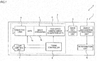
- FIG. 1 is a block diagram illustrating the configuration of an obstacle detecting apparatus according to the present embodiment using an image acquiring apparatus for a vehicle.
- FIG. 2 is a schematic diagram illustrating the temporal relationship between an operation (light emitting operation) of a light emitting unit and an operation (camera gate operation) of a gate when imaging respective target distance ranges.
- an obstacle detecting apparatus 1 which is installed in a vehicle V (the own vehicle) includes an image acquiring apparatus 2, an image processing unit (a distance image data generating unit) 3, an object recognition processing unit 4, and a determination unit 10.
- the image acquiring apparatus 2 includes a light emitting unit 5, an objective lens 6, a light intensifying unit 7, a high-speed camera (an image acquisition unit) 8, and a timing controller (a timing control unit) 9.
- the light emitting unit 5 is, for example, a near-infrared LED disposed at a front end part of the vehicle V. As shown in FIG. 2 , the light emitting unit 5 emits pulse light to a predetermined direction (for example, forward from the vehicle V) for a predetermined light emission time tL (for example, 5 ns), according to a pulse signal output from the timing controller 9.
- the light emission cycle tP of pulse light which is radiated from the light emitting unit 5 is set to, for example, an interval of 10 ⁇ s or less.
- the objective lens 6 is, for example, an optical system set so as to have such an angle of field that it is possible to image a predetermined range in front of the vehicle V, and receives reflected light from objects.
- the objective lens 6 may be disposed close to the light emitting unit 5 or may be disposed apart from the light emitting unit.
- the light intensifying unit 7 includes a gate 7a and an image intensifier 7b.
- the gate 7a is opened and closed according to an opening/closing command signal from the timing controller 9.
- an opening time (gate time) tG of the gate 7a is set to 5 ns similarly to the light emission time tL.
- the gate time tG is proportional to the imaging object length (imaging object depth) of each range (target distance range) of an overall imaging range from a range 1 to a range n. As the gate time tG is lengthened, the imaging object length of each range lengthens.
- the imaging object length is obtained from the product of light speed and the gate time tG, and in the present embodiment, since the gate time tG is 5 ns, the imaging object length becomes 1.5 m from the product of light speed (about 3 ⁇ 10 8 m/s) and the gate time (5 ns).
- the image intensifier 7b is a device for first converting very weak light (such as reflected light from objects) into electrons, and electrically amplifying them, and converting them back into a fluorescent image, thereby doubling the amount of light, such that it is possible to see an image with clear contrast.
- Light amplified by the image intensifier 7b is guided to an image sensor of the high-speed camera 8.
- the high-speed camera 8 images the image output from the light intensifying unit 7, according to a command signal from the timing controller 9, and outputs the acquired image to the image processing unit 3.
- a camera having a resolution of 640x480 (transverse: longitudinal), luminance values 1 to 255 (256 levels), and a frame rate of 100 fps or more is used.
- the timing controller 9 controls imaging timings by setting a delay time tD (in FIG. 2 , tD n , tD n+1 ) which is a time from when the light emitting unit 5 starts to emit light to when the gate 7a is opened such that the timing when an image is acquired by the high-speed camera 8 becomes the timing of reflected light returning from a target distance range which is a target imaging range and outputting opening/closing command signals according to the delay time tD.
- the delay time tD is a value to determine the distance (an imaging object distance) from the vehicle V to the target distance range.
- the relationship between the delay time tD and the imaging object distance is obtained from the following Expression (1).
- Imaging Object Distance Light Speed about 3 ⁇ 10 8 m / s ⁇ Delay Time tD / 2
- the timing controller 9 changes the image range of the high-speed camera 8 forward from the vehicle 100 by repeatedly lengthening the delay time tD by a predetermined interval (for example, 10 ns) such that the target distance range continuously goes forward (away) from the vehicle V. Also, the timing controller 9 performs control such that the imaging operation of the high-speed camera 8 starts immediately before the gate 7a is opened and the imaging operation finishes after the gate 7a is completely closed.
- a predetermined interval for example, 10 ns
- the timing controller 9 controls the light emitting unit 5, the gate 7a, and the high-speed camera 8 such that they perform a plurality of times of light emission and exposure for each of preset target distance ranges (each range of the range 1, the range 2, ..., and the range n).
- Light which the high-speed camera 8 has received is converted into electric charge, and a plurality of times of light emission and exposure is repeated, whereby the electric charge is accumulated.
- One image which is acquired every predetermined charge accumulation time is called a frame.
- the high-speed camera 8 may acquire one image (one frame) for each target distance range, or may acquire a plurality of images (several frames) for each target distance range. In the above-mentioned way, the high-speed camera 8 acquires a plurality of different images of target distance ranges, and outputs the plurality of acquired images to the image processing unit 3.
- the image processing unit 3 generates distance image data representing the distances to objects (subjects) of respective pixels, based on the luminance of the same pixels in images of all imaging ranges acquired by the high-speed camera 8, and outputs the generated distance image data to the object recognition processing unit 4.
- the object recognition processing unit 4 specifies objects included in the distance image data.
- a well-known technology such as pattern mapping can be used.
- the determination unit 10 determines the relationship (such as distances and directions) between the vehicle (the vehicle V) and the objects (such as persons, vehicles, and signs) specified by the object recognition processing unit 4.
- the timing controller 9 sets the delay time tD such that the timing when an image which is acquired by the high-speed camera 8 becomes the timing of reflected light returning from a predetermined target distance range, thereby controlling imaging timings of the high-speed camera 8.
- the time required for light emitted from the light emitting unit 5 to return from the target distance range becomes the time required for the light to travel out and back over the distance (imaging object distance) between the vehicle V and the target distance range. Therefore, the delay time tD can be obtained from the imaging object distance and the light speed.
- luminance value data of pixels corresponding to the location of the corresponding object are influenced by the reflected light, and thus represent values higher than luminance value data of the other pixels. Therefore, it is possible to obtain the distance to the object existing in the target distance range, based on the luminance value data of the respective pixels.
- FIG. 3 shows a situation where four objects A to D exist at different locations in front of the vehicle V.
- the object A is a person holding an umbrella
- the object B is a motorcycle on the oncoming lane side
- the object C is a tree on the sidewalk side
- the object D is a vehicle (an oncoming vehicle) on the oncoming lane side. It is assumed that the relationship of the distances between the vehicle V and the respective objects is A ⁇ B ⁇ C ⁇ D.
- imaging ranges are partially overlapped such that reflected light from one object is reflected in pixels of images of a plurality of continuous imaging ranges.
- the increment in the imaging object distance is set such that imaging ranges change while partially overlapping.
- FIG. 5 shows temporal luminance variations in pixels corresponding to the respective objects.
- the luminance values of the same pixels in the plurality of consecutive images represent features having triangular wave shapes in which the luminance values gradually increases and have peaks at the positions of the respective objects A to D and gradually decrease. That is, since the increment is set such that reflected light from one object is reflected in a plurality of images, the temporal luminance variations in the pixels have the triangular wave shapes. Therefore, if imaging ranges corresponding to the peaks of the triangular wave shapes are set at the distances from the vehicle V to the respective objects (subjects) A to D in the pixels, it is possible to improve detection accuracy.
- the obstacle detecting apparatus 1 having the image acquiring apparatus 2 can be used for light distribution control of a so-called AHB (automatic high beam) system and an ADB (adaptive driving beam) system.
- AHB automatic high beam
- ADB adaptive driving beam
- each light spot in the image acquired by the camera sensor It is possible to obtain the distance of each light spot in the image acquired by the camera sensor from the images acquired by the image acquiring apparatus 2, and from the distance, the luminance, the shape (the shapes of the light spot and the periphery thereof), time-series variation, and so on of each light spot, it is possible to determine whether the light spot corresponds to a vehicle. That is, by using the image acquiring apparatus 2 and another camera sensor together, it is possible to perform detection of distant vehicles with high accuracy at high speed, and it is possible to suitably perform light distribution control of an AHB system or an ADB system.
- FIG. 6 is a view for explaining the relationship between light-emission/exposure time and distance resolution.
- (A) shows distance resolution in the case where the pulse width (light emission time) of pulse light and the gate time (exposure time) of the high-speed camera are comparatively short.
- (B) of FIG 6 shows distance resolution in the case where the pulse width (light emission time) of pulse light and the gate time (exposure time) of the high-speed camera are longer than the pulse width and the gate time of (A), respectively.
- (C) and (D) of FIG. 6 show the relationships between light-emission/exposure time and imaging object distance.
- imaging object distance L is obtained from [Light Speed] ⁇ [Delay Time tD (Time tA of (C) and (D) of FIG. 6 )]/2.
- a time tA 1 from a light emission end time point of pulse light to an exposure start time point corresponds to a distance L1
- a time tA 2 from a light emission start time point of pulse light to an exposure end time point corresponds to a distance L2. Therefore, as the light emission time and the exposure time shorten as shown in (A) of FIG. 6 , an imaging object length (L2 - L1) shortens as shown in (C) of FIG. 6 , i.e. the distance resolution increases.
- the imaging object length (L2 - L1) lengthens as shown in (D) of FIG. 6 i.e. the distance resolution decreases. Therefore, by making the resolution of target distance finer as the light emission time and the exposure time shorten, it is possible to improve the accuracy of distance detection. However, since the luminance of images which are acquired becomes lower as the light emission time and the exposure time shorten, object recognition becomes difficult.
- FIG. 7 is a flow chart for determining a range of a specific distance according to a first example.
- FIG. 8 is a view illustrating the temporal relationship between a light emission cycle and imaging timings according to the first example.
- the timing controller 9 determines whether the vehicle is running at night or in a poor weather.
- the timing controller 9 can determine whether the vehicle is running at night or in a poor weather based on information from various switches or sensors (to be described below) installed in the vehicle V. In the case where it is determined in STEP S11 that the vehicle is running at night or in bad weather ("Yes" in STEP S11), the timing controller proceeds to STEP S12. Meanwhile, in the case where it is determined in STEP S11 that the vehicle is not running at night or in bad weather ("No" in STEP S11), the timing controller proceeds to STEP S13.
- Bad weather refers to weather which may result in an object recognition mistake when generating distance image data.
- bad weather is weather in which rain, fog, snow, and the like directly obstruct visual recognition of the front or moisture diffusely reflecting light exists on the road or the like. Determination on whether weather is bad is performed based on information from a wiper switch, a fog lamp switch, a raindrop sensor, and the like of the vehicle V. Also, determination on whether it is night is performed based on information from a tail lamp switch, a sensor for automatic lighting, and the like of the vehicle V. Also, a dedicated sensor for determining whether it is night may be installed.
- the timing controller 9 flags the range 1 which is a range closest to the vehicle V, i.e. sets the range 1 as a candidate for a range of the specific distance, and then proceeds to STEP S13.
- the timing controller 9 determines whether each target distance range (the ranges 1 to n) includes any range from which a recognition candidate object is detected. Detection on recognition candidate objects may be performed by image acquisition of the image acquiring apparatus 2, or detection may be performed in advance by other sensors. In the case where it is determined in STEP S13 that there is a range from which a recognition candidate object is detected ("Yes" in STEP S13), the timing controller 9 proceeds to STEP S14. Meanwhile, in the case where it is determined in STEP S13 that there is no range from which any recognition candidate object is detected ("No" in STEP S13), the timing controller 9 proceeds to STEP S15.
- the timing controller 9 flags a range closest from the vehicle V, for example, the range 1, among ranges from which recognition candidate objects are detected. In other words, the timing controller 9 sets the range 1 as a candidate for a range of the specific distance, and proceeds to STEP S15. Meanwhile, in the case where any recognition candidate object is not detected from the range 1, the timing controller 9 flags a range closest from the vehicle V, among ranges of the ranges 2 to n from which recognition candidate objects are detected.
- the timing controller 9 sets the range flagged in STEP S12 or STEP S14, as a range of the specific distance. That is, in the case where it is bad weather or night, among the target distance ranges, a range closest to the vehicle V is set as a range of the specific distance. Also, among the target distance ranges, a range from which a recognition candidate object is detected is set as a range of the specific distance, and in the case where there is a plurality of ranges from which recognition candidate objects are detected, among the plurality of ranges, a range closest to the vehicle V is set as a range of the specific distance.
- the process for determining a range of the specific distance may be performed in the high-speed camera 8, the image processing unit 3, or the like, not in the timing controller 9.
- the timing controller 9 controls the light emission cycle of pulse light and imaging timings of reflected light such that the range of the specific distance set as described above is imaged with luminance higher than that for ranges other than the range of the specific distance.
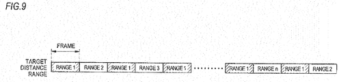
- the number of times of emission of pulse light and the number of times of exposure of the high-speed camera for imaging the range 1 are set larger than the number of times of light emission and the number of times of exposure for imaging each of the ranges 2 to n other than the range of the specific distance.
- a light emission cycle tP 1 for the range 1 is set to, for example, 1/150 ms and a light emission cycle tP 2 for the ranges 2 to n is set to 1/100 ms.
- the luminance difference between the image of the range 1 and images of the ranges 2 to n becomes larger, i.e. the contrast between the image of the range 1 and the images of the ranges 2 to n becomes higher.
- the number of times of range scan of the range 1 may be set larger than the number of times of range scan for imaging the ranges 2 to n other than the range of the specific distance.
- the number of times of range scan of the range I can be set larger than the number of times of range scan of the ranges 2 to n such that range scan of the range 1 is performed between range scan of the respective ranges 2 to n.
- FIG. 10 is a view illustrating the relationship between a range of a specific distance and other ranges according to second example.
- the light emitting unit 5 is controlled such that the light emission intensity of pulse light for imaging the range 1 becomes higher than the light emission intensity for imaging the ranges 2 to n other than the range of the specific distance. If the light emission intensity only for the range 1 of the specific distance is increased as described above, the luminance of pixels of an image of the range 1 becomes higher than the luminance of pixels of images of the ranges 2 to n. Therefore, the contrast between the image of the range 1 and the images of the ranges 2 to n becomes high. Also, since the light emission intensity for the ranges 2 to n other than the range of the specific distance is maintained at a comparatively low state, it is possible to improve the accuracy of recognition of objects without unnecessarily increasing power consumption.
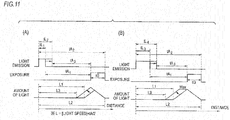
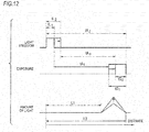
- FIG. 11 (A) and (B) are views illustrating variations in the amount of reflected light and imaging object length in the case of changing light emission time. Also, FIG. 12 is a view illustrating the relationship of light emission time and exposure time with the amount of reflected light and distance resolution according to a third example.
- control is performed such that the light emission time of pulse light for imaging the range 1 is lengthened and the exposure time of the high-speed camera 8 for imaging the range 1 is shortened.
- the light emission time tL 1 for the range 1 is lengthened to tL 2 (tL 2 > tL 1 ) and an exposure time tG 1 for the range 1 is shortened to tG 2 (tG 1 > tG 2 ).
- the exposure time tG is shortened by delaying the start time of the exposure time tG 1 .
- the exposure time is shortened by lengthening the light emission time, before and after the light emission time and the exposure time change, the time tA from the light emission end time point to the exposure start time point (tA 1 to tA 3 ) does not change significantly. Therefore, even though the light emission time is lengthened, the imaging object length does not lengthen.
- the light emission time and the exposure time shorten, it is possible to make the resolution of target distance finer, thereby improving the accuracy of distance detection.
- the luminance of an image which is acquired becomes lower as the light emission time and the exposure time shorten, it takes more time to exhaustively acquire images of a desired imaging range with high luminance, and the cost of the apparatus increases.
- a target road environment is, for example, an intersection or a blind curve where accidents are likely to occur.
- Such target road environments are acquired from map information.
- the image processing unit 3 acquires information on existence or non-existence of target road environments such as an intersection or a curve and the distances from the vehicle V to target road environments, from a navigation system or the like, and a range which should be intensively imaged is determined.
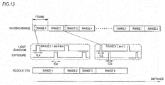
- FIG. 13 is a view illustrating the temporal relationship between a light emission cycle and imaging timings according to the fourth example.
- the light emission cycle of pulse light and imaging timings of the high-speed camera 8 are controlled such that a range of a target road environment is imaged more intensively than ranges other than the range of the target road environment.
- the timing controller 9 controls a light emission time tLb of pulse light and a gate opening time (exposure time) tGb of the high-speed camera 8 for imaging the ranges 2 and 3 such that they become shorter than a light emission time tLa and an exposure time tGa for imaging the ranges 1 and 4 to n other than the ranges 2 and 3.
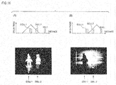
- FIG. 14 is a view illustrating the light emission intensity relationship between a range of the specific distance and other ranges according to a fifth example.
- the light emitting unit 5 is controlled such that the light emission intensity of pulse light for imaging the ranges 2 and 3 becomes higher than the light emission intensity for imaging the ranges 1 and 4 to n other than the ranges of the target road environment. If the light emission intensity for the ranges 2 and 3 of the target road environment is set higher than that for the ranges 1 and 4 to n other than the ranges of the target road environment as described above, since the luminance of pixels of images of the ranges 2 and 3 becomes higher than the luminance of pixels of images of the other the ranges 1 and 4 to n, it is possible to image only the target road environment intensively and bright. Also, since the light emission intensity for the ranges 1 and 4 to n other than the ranges of the target road environment are maintained at a comparatively low state, it is possible to improve the accuracy of recognition of objects without unnecessarily increasing power consumption.
- a sixth example will be described with reference to FIG. 11 and FIG. 12 used in the description of the third example.
- control is performed such that the light emission time of pulse light for imaging the ranges 2 and 3 is lengthened and the exposure time of the high-speed camera 8 for imaging the ranges 2 and 3 is shortened (see FIG. 12 ).
- the light emission time tL 1 for the range 1 is lengthened to tL 2 (tL 2 > tL 1 ) and an exposure time tG 1 for the range 1 is shortened to tG 2 (tG 1 > tG 2 ).
- the exposure time tG is shortened by delaying the start time of the exposure time tG 1 .
- the exposure time is shortened by lengthening the light emission time, before and after the light emission time and the exposure time change, the time tA from the light emission end time point to the exposure start time point (tA 1 to tA 3 ) does not change significantly. Therefore, even though the light emission time is lengthened, the imaging object length does not lengthen, i.e. the distance resolution does not deteriorate.
- target distance ranges for example, 0 m to 200 m in front of the vehicle
- the distance resolution decreases, it takes more time required to exhaustively acquire images of the target distance ranges, and the cost of the apparatus increases.
- FIG. 15 is a view illustrating an object search method according to the seventh example.
- the timing controller 9 (an example of a search process control unit) performs a search process sequence of searching existence or non-existence of objects in front of the vehicle, before the image acquiring process described above.
- a search frame for roughly searching existence or non-existence of objects and the distances to objects, and an imaging frame for acquiring images by imaging predetermined target distance ranges changing continuously are provided, and the search frame is disposed before the imaging frame.
- the search frame includes a plurality of times of search (search 1 to search n).
- the imaging frame includes imaging of the overall imaging range of the ranges I to n.
- One search frame can be provided with respect to one imaging frame or with respect to a plurality of imaging frames.
- one search frame may be performed by first performing a search frame and performing the plurality of imaging frames from the imaging frame 1 to the imaging frame n and then performing a search frame again.
- the timing controller 9 can control the light emission cycle of pulse light of the light emitting unit 5 and imaging timings of the high-speed camera 8 such that a search frame which is a step of searching existence or non-existence of objects is provided before an imaging frame including a step of outputting pulse light and a step of imaging reflected light.
- FIG 16 shows schematic diagrams of imaging of a specific distance and acquired images. Specifically, (A) of FIG. 16 shows a schematic diagram of the case where there is no object at a distance shorter than the specific distance, and an acquired image, and (B) of FIG. 16 shows a schematic diagram of the case where there is an object at a distance shorter than the specific distance, and an acquired image. Also, FIG. 17 is a view illustrating a sequence process for search distance determination according to the seventh example.
- FIG 16 is a view illustrating the case where there is a plurality of objects at different distances from the vehicle in the same direction in front of the vehicle.
- a doll 1, a doll 2, and a wall exist sequentially from the near side.
- imaging is performed in (A) of FIG. 16 .
- imaging is performed in (B) of FIG 16 .
- a search object range is determined. Specifically, in the case where a distance range (a target distance range) which is a desired imaging object is 0 m to 200 m in front of the vehicle, search processes from search 1 to search 4 shown in FIG 17 are performed.
- the timing controller 9 controls the high-speed camera 8 such that the high-speed camera images a range a (from 100 m to 200 m) which is a range far from the vehicle among target distance ranges (0 m to 200 m). Then, in the case where the image of the range a has a black pixel area, the timing controller 9 controls the high-speed camera 8 such that the high-speed camera images a range b (50 m to 100 m) far from the vehicle among ranges (0 m to 100 m) closer than the range a is.
- the timing controller 9 controls the high-speed camera 8 such that the high-speed camera images a range c (50 m to 100 m) which is a range of the range a far from the vehicle. Also, determination on whether there is any black pixel area can be performed based on the sizes and shapes of pixel areas having luminance lower than a threshold.
- the timing controller 9 performs an imaging process of any one of ranges d to g.
- the timing controller 9 controls the high-speed camera 8 such that the high-speed camera images the range d (25 m to 50 m) which is a range far from the vehicle among ranges (0 m to 50 m) closer than the range b is. Meanwhile, in the case where the image of the range b does not have any black pixel area, the timing controller 9 controls the high-speed camera 8 such that the high-speed camera images the range e (75 m to 100 m) which is a range of the range b far from the vehicle.
- the timing controller 9 controls the high-speed camera 8 such that the high-speed camera images the range f (125 m to 150 m) which is a range included in a range (100 m to 150 m) of the range a far from the vehicle and is closer than the range c is. Meanwhile, in the case where the image of the range c does not have any black pixel area, the timing controller 9 controls the high-speed camera 8 such that the high-speed camera images the range g (175 m to 200 m) which is a range of the range c far from the vehicle.
- the timing controller 9 performs an imaging process of any one of ranges h to k.
- the timing controller 9 controls the high-speed camera 8 such that the high-speed camera images the range h (12.5 m to 25 m), which is a range included in a range (0 m to 25 m) closer than the range d and far from the vehicle. Meanwhile, in the case where the image of the range d does not have any black pixel area, the timing controller 9 controls the high-speed camera 8 such that the high-speed camera images the range i (37.5 m to 50 m) which is a range of the range d far from the vehicle.
- the timing controller 9 controls the high-speed camera 8 such that the high-speed camera images the range j (62.5 m to 75 m), which is a range included in a range (50 m to 75 m) of the range b closer than the range e and far from the vehicle. Meanwhile, in the case where the image of the range e does not have any black pixel area, the timing controller 9 controls the high-speed camera 8 such that the high-speed camera images the range k (87.5 m to 100 m) which is a range of the range e far from the vehicle.
- the timing controller 9 controls the high-speed camera 8 such that the high-speed camera images a range I (112.5 m to 125 m) which is a range included in a range (100 m to 125 m) of the range a closer than the range f and far from the vehicle. Meanwhile, in the case where the image of the range f does not have any black pixel area, the timing controller 9 controls the high-speed camera 8 such that the high-speed camera images a range m (137.5 m to 150m) which is a range of the range f far from the vehicle.
- the timing controller 9 controls the high-speed camera 8 such that the high-speed camera images a range n (162.5 m to 175 m), which is a range included in a range (150 m to 175 m) of the range c closer than the range g is and far from the vehicle. Meanwhile, in the case where the image of the range g does not have any black pixel area, the timing controller 9 controls the high-speed camera 8 such that the high-speed camera images the range o (187.5 m to 200 m) which is a range of the range g far from the vehicle.
- the timing controller 9 determines a range where there is an object.
- the timing controller 9 determines that an object exits in the range from 0 m to 12.5 m. Meanwhile, in the case where the image acquired by imaging the range h does not have any black pixel area, the timing controller 9 determines that an object exists in the range from 12.5 m to 25 m.
- the timing controller 9 determines that an object exists in the range from 25 m to 37.5 m. Meanwhile, in the case where the image acquired by imaging the range i does not have any black pixel area, the timing controller 9 determines that an object exists in the range from 37.5 m to 50 m.
- the timing controller 9 determines that an object exists in the range from 50 m to 62.5 m. Meanwhile, in the case where the image acquired by imaging the range j does not have any black pixel area, the timing controller 9 determines that an object exists in the range from 62.5 m to 75 m.
- the timing controller 9 determines that an object exists in the range from 75 m to 87.5 m. Meanwhile, in the case where the image acquired by imaging the range k does not have any black pixel area, the timing controller 9 determines that an object exists in the range from 87.5 m to 100 m.
- the timing controller 9 determines that an object exists in the range from 100 m to 112.5 m. Meanwhile, in the case where the image acquired by imaging the range I does not have any black pixel area, the timing controller 9 determines that an object exists in the range from 112.5 m to 125 m.
- the timing controller 9 determines that an object exists in the range from 125 m to 137.5 m. Meanwhile, in the case where the image acquired by imaging the range m does not have any black pixel area, the timing controller 9 determines that an object exists in the range from 137.5 m to 150 m.
- the timing controller 9 determines that an object exists in the range from 150m to 162.5 m. Meanwhile, in the case where the image acquired by imaging the range n does not have any black pixel area, the timing controller 9 determines that an object exists in the range from 162.5 m to 175 m.
- the timing controller 9 determines that an object exists in the range from 175 m to 187.5 m. Meanwhile, in the case where the image acquired by imaging the range o does not have any black pixel area, the timing controller 9 determines that an object exists in the range from 187.5 m to 200 m.
- the timing controller 9 performs control such that the range where the object exists is intensively imaged. Specifically, as shown in (A) to (C) of FIG. 18 , for example, in the case where a range where an object exists is the range I of the ranges 1 to n, by setting the number of times of light emission and the number of times of exposure for the range 1 larger than those for the other the ranges 2 to n, or setting the light emission intensity for the range 1 higher than the light emission intensity for the ranges 2 to n, or setting the light emission time for the range 1 longer than the exposure time, it is possible to intensively image the range 1.
- control is performed such that the number of times of light emission and the exposure time are not unnecessarily increased and the light emission intensity is not unnecessarily increased.
- the timing controller 9 performs the step of searching existence or non-existence of objects before performing the step of acquiring images by emitting pulse light and imaging reflected light of the pulse light.
- the step of searching existence or non-existence of objects in advance is provided, in the step of acquiring images, it is possible to intensively image a distance range where an object exists among the target distance ranges. Therefore, it is possible to improve the accuracy of object recognition while preventing increase in the time required to exhaustively acquire images of the target distance ranges and the cost.
- FIG. 19 is a view illustrating a sequence process for search distance determination according to an eighth example.
- 0 m to 200 m in front of the vehicle is set as a distance range (a target distance range) which is a desired imaging object.
- the timing controller 9 controls the light emitting unit 5 such that the light emitting unit emits light once, and performs exposure (a gate opening/closing operation) once.
- the exposure timing and the exposure time are controlled such that it is possible to image the range a (100 m to 200 m) which is a range far from the vehicle.
- the timing controller 9 detects existence or non-existence of a black pixel area in the image of the range a (100 m to 200 m), thereby determining whether there is any object in the range a.
- the timing controller 9 controls the light emitting unit 5 such that the light emitting unit emits light twice, and performs exposure (a gate opening/closing operation) once.
- the exposure timing and the exposure time are controlled such that it is possible to receive reflected light according to light emission performed twice, thereby imaging the range b (50 m to 100 m) and the range c (150 m to 200 m).
- the timing controller 9 detects existence or non-existence of a black pixel area in the images of the range b (50 m to 100 m) and the range c (150 m to 200 m), thereby determining whether there is any object in the range b or the range c.
- the timing controller 9 controls the light emitting unit 5 such that the light emitting unit emits light four times, and performs exposure (a gate opening/closing operation) once.
- the exposure timing and the exposure time are controlled such that it is possible to receive reflected light according to light emission performed four times, thereby imaging the range d (25 m to 50 m), the range e (75 m to 100 m), the range f (125 m to 150 m), and the range g (175 m to 200 m).
- the timing controller 9 detects existence or non-existence of a black pixel area in the images of the range d (25 m to 50 m), the range e (75 m to 100 m), the range f (125 m to 150 m), and the range g (175 m to 200 m), thereby determining whether there is any object in any one of the ranges d to g.
- the timing controller 9 controls the light emitting unit such that the light emitting unit emits light eight times, and performs exposure (a gate opening/closing operation) once.
- the exposure timing and the exposure time are controlled such that it is possible to image the range h (12.5 m to 25 m), the range i (37.5 m to 50 m), the range j (62.5 m to 75 m), the range k (87.5 m to 100 m), the range I (112.5 m to 125 m), the range m (137.5 m to 150 m), the range n (162.5 m to 175 m), and the range o (187.5 m to 200 m).
- the timing controller 9 detects existence or non-existence of a black pixel area in the images of the range h (12.5 m to 25 m), the range i (37.5 m to 50 m), the range j (62.5 m to 75 m), the range k (87.5 m to 100 m), the range 1 (112.5 m to 125 m), the range m (137.5 m to 150 m), the range n (162.5 m to 175 m), and the range o (187.5 m to 200 m), thereby determining whether there is any object in any one of the ranges h to o.
- a range where an object exists is measured by imaging light emitted a plurality of times by performing exposure once; however, this disclosure is not limited to this configuration.
- this disclosure is not limited to this configuration.
- a plurality of times of exposure may be performed to measure a range where an object exists. Even according to the sequence process shown in FIG 20 , it is possible to search an object existing at the shortest distance from the vehicle by search of four frames.
- a distance range where an object exists is narrowed down by emitting pulse light a plurality of times and imaging reflected light a plurality of times. According to this configuration, similarly to the seventh example, it is possible to search an object existing at the shortest distance by a small number of frames.
- the imaging object length, the amount of change in the imaging object distance, the number of frames for each target distance range, and so on can be appropriately set according to the performance of the high-speed camera 8 and the image processing unit 3.
- the high-speed camera 8 functions as an image acquisition unit; however, this disclosure is not limited to this example.
- the image processing unit 3 may have the function of an image acquisition unit, or a separate memory for storing images may be provided as an image acquisition unit between the high-speed camera 8 and the image processing unit 3.
- the light intensifying unit 7 (the gate 7a and the image intensifier 7b) is installed between the objective lens 6 and the high-speed camera 8; however, this disclosure is not limited to this example.
- the light intensifying unit 7 it is possible to acquire a plurality of images by performing gating in the high-speed camera 8 at predetermined imaging timings.
- object recognition is performed by generating distance image data by the image processing unit 3; however, object recognition may be performed from images of respective target distances acquired by the high-speed camera 8.
Landscapes
- Engineering & Computer Science (AREA)
- Physics & Mathematics (AREA)
- Computer Networks & Wireless Communication (AREA)
- General Physics & Mathematics (AREA)
- Radar, Positioning & Navigation (AREA)
- Remote Sensing (AREA)
- Electromagnetism (AREA)
- Optical Radar Systems And Details Thereof (AREA)
Abstract
Description
- This disclosure relates to an image acquiring apparatus for a vehicle, a control device, a vehicle having the image acquiring apparatus for a vehicle or the control device, and an image acquiring method for a vehicle.
-
Patent Document 1 discloses a distance image data generating apparatus, which emits pulse light forward from a vehicle having the distance image data generating apparatus in a predetermined cycle and images the reflected light from target distances at imaging timings set according to the target distances, thereby acquiring a plurality of different images of the target distances, and generates distance image data representing the distance to an object of each pixel, based on the luminance of the same pixel in the images. - Patent Document 1:
JP-A-2009-257983 - In the distance image data generating apparatus for a vehicle disclosed in
Patent Document 1, it is possible to increase the accuracy of distance detection by making target distance resolution finer while the light emission time of pulse light and the imaging (exposure) time of reflected light are shortened. However, as the light emission time and the imaging time are shortened, the luminance of acquired images is lower and object recognition becomes difficult. If the light emission intensity is simply increased or the light emission pulse width is simply lengthened, power consumption increases. Further, if the number of times of light emission and the number of times of exposure are simply increased, the frame rate becomes high, and the time required to exhaustively acquire images of all imaging ranges which are imaging targets becomes longer. - Also, in the distance image data generating apparatus for a vehicle disclosed in
Patent Document 1, according to the light emission time of pulse light and the imaging (exposure) time of reflected light, distance resolution is determined. In order to increase the accuracy of distance detection, it is desirable that distance resolution be finer (a range width corresponding to one frame be shorter). Also, it is desirable to image all of target distance ranges (for example, 0 m to 200 m in front of the vehicle), which are distance ranges corresponding to desired imaging targets, bright with fine distance resolution. However, as distance resolution is finer, it takes more time to exhaustively acquire distance images of a desired imaging range and the cost of the apparatus increases. - Accordingly, a first object of this disclosure is to provide an image acquiring apparatus for a vehicle, a control device, a vehicle having the image acquiring apparatus for a vehicle or the control device, and an image acquiring method for a vehicle, capable of improving the accuracy of recognition of objects in acquired images while maintaining fine distance resolution.
- Also, a second object of this disclosure is to provide an image acquiring apparatus for a vehicle, a control device, a vehicle having the image acquiring apparatus for a vehicle or the control device, and an image acquiring method for a vehicle, capable of preventing increase in the time required to exhaustively acquire distance images of a desired imaging range and in the cost while maintaining the accuracy of object recognition.
- Further, a third object of this disclosure is to provide an image acquiring method for a vehicle, an image acquiring apparatus for a vehicle, a control device, and a vehicle having the image acquiring apparatus for a vehicle or the control device for intensively imaging distance ranges of target distance ranges in which an object exists.
- In order to achieve the first object, an image acquiring apparatus for a vehicle according to this disclosure includes:
- a light emitting unit configured to emit pulse light to a predetermined direction;
- an image acquisition unit configured to acquire a plurality of different images of target distance ranges by imaging reflected light returning from the target distance ranges at imaging timings set according to the target distance ranges; and
- a timing control unit configured to control a light emission cycle of the pulse light and the imaging timings,
- wherein the timing control unit is configured to control at least one of the light emission cycle and the imaging timings such that among different target distance ranges, a range of a specific distance necessary for object recognition is imaged with luminance higher than that for ranges other than the range of the specific distance.
- According to the above-described configuration, by imaging only the range of the specific distance necessary for object recognition with high luminance (bright), the luminance contrast between the image of the range of the specific distance where an object may exist and the images of the ranges other than the range of the specific distance becomes clear. Therefore, recognition of an object in the range of the specific distance becomes easy. Therefore, it is possible to improve the accuracy of recognition of objects in the image while maintaining fine distance resolution, and thus it is possible to improve light control and vehicle control.
- When it is bad weather or night, the range of the specific distance may be a range closest to the image acquisition unit among the target distance ranges.
- According to the above-described configuration, by bright imaging the range which is closest to the image acquisition unit and to which most attention should be paid, it is possible to improve the accuracy of recognition of objects and contribute to safe driving in rainy weather or at night.
- The range of the specific distance may be a range from which a recognition candidate object is detected among the target distance ranges.
- According to the above-described configuration, by performing detection of objects which are recognition candidates in advance, it is possible to improve the accuracy of recognition of objects.
- When there are a plurality of ranges from which the recognition candidate object is detected, the range of the specific distance may be set to a range closest to the image acquisition unit among the plurality of ranges.
- According to the above-described configuration, when there are a plurality of recognition candidate objects, by bright imaging an object closest to the image acquisition unit, it is possible to improve the accuracy of recognition of an object which should be given most attention.
- The timing control unit may be configured to set a number of times of light emission of the pulse light and a number of times of exposure of the image acquisition unit for the range of the specific distance larger than those for the ranges other than the range of the specific distance.
- According to the above-described configuration, by increasing the number of times of light emission and the number of times of exposure only for the range of the specific distance, it is possible to improve the accuracy of recognition of objects without unnecessarily increasing power consumption and without unnecessarily increasing the frame rate.
- The light emitting unit may be controlled such that a light emission intensity of the pulse light for the range of the specific distance becomes higher than that for the ranges other than the range of the specific distance.
- According to the above-described configuration, by increasing the light emission intensity only for the range of the specific distance, it is possible to improve the accuracy of recognition of objects without unnecessarily increasing power consumption.
- The timing control unit may be configured to lengthen a light emission time of the pulse light while shortening an exposure time of the image acquisition unit for the range of the specific distance as compared to the ranges other than the range of the specific distance.
- According to the above-described configuration, by lengthening the light emission time while shortening the exposure time only for the range of the specific distance, it is possible to improve the accuracy of recognition of objects while maintaining fine distance resolution.
- Also, in order to achieve the first object, a control device according to this disclosure is a control device for controlling an image acquiring apparatus for a vehicle which includes a light emitting unit configured to emit pulse light to a predetermined direction, and an image acquisition unit configured to acquire a plurality of different images of target distance ranges by imaging reflected light returning from the target distance ranges at imaging timings set according to the target distance ranges, and is configured to control at least one of a light emission cycle of the pulse light and the imaging timings such that a range of a specific distance necessary for object recognition among different target distance ranges is imaged with luminance higher than that for ranges other than the range of the specific distance.
- According to the above-described configuration, since recognition of objects in the range of the specific distance becomes easy, it is possible to improve the accuracy of recognition of objects in the image while maintaining fine distance resolution, and thus it is possible to improve light control and vehicle control.
- Also, in order to achieve the first object, an image acquiring method for a vehicle according to this disclosure is an image acquiring method for a vehicle which acquires a plurality of different images of target distance ranges by imaging reflected light of pulse light emitted to a predetermined direction while changing imaging timings and includes controlling at least one of a light emission cycle of the pulse light and the imaging timings such that a range of a specific distance necessary for object recognition among different target distance ranges is imaged with luminance higher than that for ranges other than the range of the specific distance.
- According to the above-described configuration, it is possible to improve the accuracy of recognition of objects in the image while maintaining fine distance resolution.
- In order to achieve the second object, an image acquiring apparatus for a vehicle according to this disclosure includes:
- a light emitting unit configured to emit pulse light to a predetermined direction;
- an image acquisition unit configured to acquire a plurality of different images of target distances by imaging reflected light returning from the target distance ranges at imaging timings set according to the target distance ranges; and
- a timing control unit configured to control the light emission cycle of the pulse light and the imaging timings,
- wherein the timing control unit is configured to control at least one of the light emission cycle and the imaging timings such that among different target distance ranges, a range of a target road environment is imaged more intensively than ranges other than the range of the target road environment are.
- According to the above-described configuration, by intensively imaging only the range of the target road environment, it is possible to grasp the distances to objects with high accuracy, and it is possible to prevent increase in the time required to exhaustively acquire images of a desired imaging range and the cost. Also, since the luminance contrast between the range of the target road environment and the other ranges becomes clear, recognition of recognition candidate objects in the target road environment becomes easy. Therefore, it is possible to improve light control and vehicle control.
- The target road environment may include an intersection or a curve and may be acquired from map information.
- According to the above-described configuration, by acquiring an intersection or a curve where accidents are likely to occur from map information and intensively imaging the intersection or the curve, it is possible to reduce traffic accidents.
- The timing control unit may be configured to set the light emission cycle of the pulse light and an exposure time of the image acquisition unit for the range of the target road environment shorter than those for ranges other than the range of the target road environment.
- According to the above-described configuration, by shortening the light emission time and the exposure time for the range of the target road environment, it is possible to improve the distance resolution of the range of the target road environment.
- The timing control unit may be configured to lengthen a light emission time of the pulse light while shortening an exposure time of the acquisition unit for the range of the target road environment as compared to the ranges other than the range of the target road environment.
- According to the above-described configuration, it is possible to image the range of the target road environment bright, and it is possible to improve the accuracy of recognition of objects.
- The timing control unit may be configured to set a light emission intensity of the pulse light for the range of the target road environment higher than that for the ranges other than the range of the target road environment.
- According to the above-described configuration, it is possible to image the range of the target road environment bright, and it is possible to improve the accuracy of recognition of objects.
- Also, in order to achieve the second object, a control device of this disclosure is a control device for controlling an image acquiring apparatus for a vehicle which includes a light emitting unit configured to emit pulse light to a predetermined direction, and an image acquisition unit configured to acquire a plurality of different images of target distance ranges by imaging reflected light returning from the target distance ranges at imaging timings set according to the target distance ranges, and is configured to control at least one of a light emission cycle and the imaging timings such that among different target distance ranges, a range of a target road environment is imaged more intensively than ranges other than the range of the target road environment are.
- According to the above-described configuration, by intensively imaging only the range of the target road environment, it is possible to grasp the distances to objects with high accuracy, and recognition of recognition candidate objects in the target road environment becomes easy.
- Also, in order to achieve the second object, an image acquiring method for a vehicle according to this disclosure is an image acquiring method for a vehicle which acquires a plurality of different images of target distance ranges by imaging reflected light of pulse light emitted to a predetermined direction while changing imaging timings, and includes controlling at least one of a light emission cycle of the pulse light and the imaging timings such that among different target distance ranges, a range of a target road environment is imaged more intensively than ranges other than the range of the target road environment are.
- According to the above-described configuration, by intensively imaging only the range of the target road environment, it is possible to grasp the distances to objects with high accuracy, and recognition of recognition candidate objects in the target road environment becomes easy.
- In order to achieve the third object, an image acquiring method for a vehicle according to this disclosure is an image acquiring method for a vehicle which includes emitting pulse light to a predetermined direction in a predetermined cycle while changing imaging timings, acquiring a plurality of different images of target distances by imaging reflected light returning from target distance ranges at imaging timings set according to the target distance ranges, and further includes searching existence or non-existence of an object before emitting the pulse light.
- According to the above-described configuration, since the step of searching existence or non-existence of objects is provided in advance, in the step of emitting the pulse light and the step of imaging the reflected light of the pulse light, it is possible to intensively image a distance range where an object exists among the target distance ranges. Therefore, it is possible to improve the accuracy of object recognition while preventing increase in the time required to exhaustively acquire images of the target distance ranges and the cost.
- The step of searching existence or non-existence of an object may include providing a search frame for searching existence or non-existence of an object and a distance thereof before an imaging frame for imaging predetermined distance ranges changing continuously.
- According to the above-described configuration, it is possible to search existence or non-existence of an object before the image acquiring process by an easy method.
- The step of searching existence or non-existence of an object may include: dividing the target distance ranges into a close range close to the own vehicle and a far range far from the own vehicle; setting the far range as a first search range; determining whether an image of the far range acquired by imaging reflected light from the far range includes a predetermined image area; and detecting a distance of an object closest to the own vehicle by determining a next search range according to existence or non-existence of the predetermined image area.
- According to the above-described configuration, it is possible to search an object existing at the shortest distance by a small number of frames.
- The predetermined image area may include a pixel area having a luminance value equal to or smaller than a threshold.
- According to the above-described configuration, it is possible to search existence or non-existence of an object by a simple process.
- The step of searching existence or non-existence of an object may include narrowing a distance range where an object exists by emitting the pulse light a plurality of times or imaging the reflected light a plurality of times.
- According to the above-described configuration, it is possible to search an object existing at the shortest distance by a small number of frames,
- Also, in order to achieve the third object, an image acquiring apparatus for a vehicle according to this disclosure includes:
- a light emitting unit configured to emit pulse light to a predetermined direction;
- an image acquisition unit configured to acquire a plurality of different images of target distances by imaging reflected light returning from the target distances at imaging timings set according to the target distances;
- a timing control unit configured to control a light emission cycle of the pulse light and the imaging timings; and
- a search process control unit configured to search existence or non-existence of an object before the light emitting unit emits the pulse light.
- According to the above-described configuration, by searching existence or non-existence of an object in advance, it is possible to intensively image a distance range where an object exists among the target distance ranges. Therefore, it is possible to improve the accuracy of object recognition while preventing increase in the time required to exhaustively acquire distance images of the target distance ranges and the cost.
- Also, in order to achieve the third object, a control device of this disclosure is a control device for controlling an image acquiring apparatus for a vehicle which includes a light emitting unit configured to emit pulse light to a predetermined direction, and an image acquisition unit configured to acquire a plurality of different images of target distance ranges by imaging reflected light returning from the target distance ranges at imaging timings set according to the target distance ranges, and includes a search process control unit configured to search existence or non-existence of an object before the light emitting unit emits the pulse light.
- According to the above-described configuration, by searching existence or non-existence of an object in advance, it is possible to intensively image a distance range where an object exists among the target distance ranges, and it is possible to improve the accuracy of object recognition while preventing increase in the time required to exhaustively acquire distance images of the target distance ranges and the cost.
- Also, in order to achieve the first to third objects, a vehicle of this disclosure includes the image acquiring apparatus for a vehicle or the control device described above.
- According to the above-described configuration, it is possible to improve the safety of a vehicle having, for example, a self-driving system.
- According to this disclosure, it is possible to improve the accuracy of recognition of objects in acquired images while maintaining fine distance resolution.
- Also, according to this disclosure, it is possible to prevent increase in the time required to exhaustively acquire images of a desired imaging range while improving the accuracy of object recognition.
-
-
FIG. 1 is a block diagram illustrating the configuration of an obstacle detecting apparatus of an embodiment. -
FIG 2 is a view illustrating the temporal relationship between an operation (light emitting operation) of a light emitting unit and an operation (camera gate operation) of a gate when imaging respective target distance ranges. -
FIG 3 is a view illustrating a situation where four different objects exist at different positions in front of the own vehicle. -
FIG. 4 is a view illustrating a state where imaging ranges partially overlap. -
FIG 5 is a schematic diagram illustrating temporal luminance variations in pixels corresponding to respective objects. -
FIG 6 is a view for explaining the relationship between light-emission/exposure time and distance resolution. -
FIG 7 is a flow chart illustrating a process of determining a range of a specific distance according to a first example. -
FIG. 8 is a view illustrating a light emission cycle and imaging timings according to the first example. -
FIG. 9 is a view illustrating the temporal relationship between a light emission cycle and imaging timings according to another example of the first example. -
FIG. 10 is a view illustrating the light emission intensity relationship between a range of a specific distance and other ranges. -
FIG 11 is a view illustrating variations in the amount of reflected light and imaging object length in the case of changing light emission time. -
FIG. 12 is a view illustrating the relationship of light emission time and exposure time with the amount of reflected light and distance resolution according to a third example and a sixth example. -
FIG. 13 is a view illustrating a light emission cycle and imaging timings according to a fourth example. -
FIG 14 is a view illustrating the light emission intensity relationship between a range of a specific distance and other ranges according to a fifth example. -
FIG 15 is a view illustrating an object search method according to a seventh example. -
FIG. 16 shows schematic diagrams of imaging of a specific distance and acquired images, according to the seventh example, wherein (A) shows a schematic diagram of the case where there is no object at a distance shorter than the specific distance and an acquired image, and (B) shows a schematic diagram of the case where there is an object at a distance shorter than the specific distance and an acquired image. -
FIG. 17 is a view illustrating a sequence process for search distance determination according to the seventh example. -
FIG 18 is a view illustrating examples of light emission cycles and imaging timings according to the seventh example. -
FIG. 19 is a view illustrating a sequence process for search distance determination according to an eighth example. -
FIG 20 is a view illustrating a sequence process for search distance determination according to another example of the eighth example. - Hereinafter, an example of an embodiment will be described in detail with reference to the drawings.
-
FIG. 1 is a block diagram illustrating the configuration of an obstacle detecting apparatus according to the present embodiment using an image acquiring apparatus for a vehicle.FIG. 2 is a schematic diagram illustrating the temporal relationship between an operation (light emitting operation) of a light emitting unit and an operation (camera gate operation) of a gate when imaging respective target distance ranges. - As shown in
FIG 1 , anobstacle detecting apparatus 1 which is installed in a vehicle V (the own vehicle) includes animage acquiring apparatus 2, an image processing unit (a distance image data generating unit) 3, an objectrecognition processing unit 4, and adetermination unit 10. - The
image acquiring apparatus 2 includes alight emitting unit 5, an objective lens 6, a light intensifying unit 7, a high-speed camera (an image acquisition unit) 8, and a timing controller (a timing control unit) 9. - The
light emitting unit 5 is, for example, a near-infrared LED disposed at a front end part of the vehicle V. As shown inFIG. 2 , thelight emitting unit 5 emits pulse light to a predetermined direction (for example, forward from the vehicle V) for a predetermined light emission time tL (for example, 5 ns), according to a pulse signal output from the timing controller 9. The light emission cycle tP of pulse light which is radiated from thelight emitting unit 5 is set to, for example, an interval of 10 µs or less. - The objective lens 6 is, for example, an optical system set so as to have such an angle of field that it is possible to image a predetermined range in front of the vehicle V, and receives reflected light from objects. The objective lens 6 may be disposed close to the
light emitting unit 5 or may be disposed apart from the light emitting unit. - The light intensifying unit 7 includes a
gate 7a and animage intensifier 7b. - The
gate 7a is opened and closed according to an opening/closing command signal from the timing controller 9. In the present embodiment, an opening time (gate time) tG of thegate 7a is set to 5 ns similarly to the light emission time tL. The gate time tG is proportional to the imaging object length (imaging object depth) of each range (target distance range) of an overall imaging range from arange 1 to a range n. As the gate time tG is lengthened, the imaging object length of each range lengthens. The imaging object length is obtained from the product of light speed and the gate time tG, and in the present embodiment, since the gate time tG is 5 ns, the imaging object length becomes 1.5 m from the product of light speed (about 3×10⁸ m/s) and the gate time (5 ns). - The
image intensifier 7b is a device for first converting very weak light (such as reflected light from objects) into electrons, and electrically amplifying them, and converting them back into a fluorescent image, thereby doubling the amount of light, such that it is possible to see an image with clear contrast. Light amplified by theimage intensifier 7b is guided to an image sensor of the high-speed camera 8. - The high-
speed camera 8 images the image output from the light intensifying unit 7, according to a command signal from the timing controller 9, and outputs the acquired image to theimage processing unit 3. In the present embodiment, a camera having a resolution of 640x480 (transverse: longitudinal),luminance values 1 to 255 (256 levels), and a frame rate of 100 fps or more is used. - The timing controller 9 controls imaging timings by setting a delay time tD (in
FIG. 2 , tDn, tDn+1) which is a time from when thelight emitting unit 5 starts to emit light to when thegate 7a is opened such that the timing when an image is acquired by the high-speed camera 8 becomes the timing of reflected light returning from a target distance range which is a target imaging range and outputting opening/closing command signals according to the delay time tD. In other words, the delay time tD is a value to determine the distance (an imaging object distance) from the vehicle V to the target distance range. The relationship between the delay time tD and the imaging object distance is obtained from the following Expression (1).
- The timing controller 9 changes the image range of the high-
speed camera 8 forward from thevehicle 100 by repeatedly lengthening the delay time tD by a predetermined interval (for example, 10 ns) such that the target distance range continuously goes forward (away) from the vehicle V. Also, the timing controller 9 performs control such that the imaging operation of the high-speed camera 8 starts immediately before thegate 7a is opened and the imaging operation finishes after thegate 7a is completely closed. - The timing controller 9 controls the
light emitting unit 5, thegate 7a, and the high-speed camera 8 such that they perform a plurality of times of light emission and exposure for each of preset target distance ranges (each range of therange 1, therange 2, ..., and the range n). Light which the high-speed camera 8 has received is converted into electric charge, and a plurality of times of light emission and exposure is repeated, whereby the electric charge is accumulated. One image which is acquired every predetermined charge accumulation time is called a frame. However, the high-speed camera 8 may acquire one image (one frame) for each target distance range, or may acquire a plurality of images (several frames) for each target distance range. In the above-mentioned way, the high-speed camera 8 acquires a plurality of different images of target distance ranges, and outputs the plurality of acquired images to theimage processing unit 3. - The
image processing unit 3 generates distance image data representing the distances to objects (subjects) of respective pixels, based on the luminance of the same pixels in images of all imaging ranges acquired by the high-speed camera 8, and outputs the generated distance image data to the objectrecognition processing unit 4. - The object
recognition processing unit 4 specifies objects included in the distance image data. As the object specifying method, a well-known technology such as pattern mapping can be used. - The
determination unit 10 determines the relationship (such as distances and directions) between the vehicle (the vehicle V) and the objects (such as persons, vehicles, and signs) specified by the objectrecognition processing unit 4. - Next, an image acquiring operation according to the present embodiment will be described.
- The timing controller 9 sets the delay time tD such that the timing when an image which is acquired by the high-
speed camera 8 becomes the timing of reflected light returning from a predetermined target distance range, thereby controlling imaging timings of the high-speed camera 8. In the case where there is any object in a target distance range, the time required for light emitted from thelight emitting unit 5 to return from the target distance range becomes the time required for the light to travel out and back over the distance (imaging object distance) between the vehicle V and the target distance range. Therefore, the delay time tD can be obtained from the imaging object distance and the light speed. - In an image of the high-
speed camera 8 acquired by the above-mentioned method, in the case where there is an object in the target distance range, luminance value data of pixels corresponding to the location of the corresponding object are influenced by the reflected light, and thus represent values higher than luminance value data of the other pixels. Therefore, it is possible to obtain the distance to the object existing in the target distance range, based on the luminance value data of the respective pixels. -
FIG. 3 shows a situation where four objects A to D exist at different locations in front of the vehicle V. The object A is a person holding an umbrella, and the object B is a motorcycle on the oncoming lane side, and the object C is a tree on the sidewalk side, and the object D is a vehicle (an oncoming vehicle) on the oncoming lane side. It is assumed that the relationship of the distances between the vehicle V and the respective objects is A < B < C < D. - In this case, in the present embodiment, imaging ranges are partially overlapped such that reflected light from one object is reflected in pixels of images of a plurality of continuous imaging ranges. In other words, as shown in
FIG. 4 , in the case of acquiring images while continuously changing the imaging object distance in the order of B1, B2, B3, ..., by setting the increment (B2 - B1) in the imaging object distance shorter than an imaging object length A of each imaging range, the increment in the imaging object distance is set such that imaging ranges change while partially overlapping. -
FIG. 5 shows temporal luminance variations in pixels corresponding to the respective objects. - Since the imaging ranges are partially overlapped, as shown in
FIG. 5 , the luminance values of the same pixels in the plurality of consecutive images represent features having triangular wave shapes in which the luminance values gradually increases and have peaks at the positions of the respective objects A to D and gradually decrease. That is, since the increment is set such that reflected light from one object is reflected in a plurality of images, the temporal luminance variations in the pixels have the triangular wave shapes. Therefore, if imaging ranges corresponding to the peaks of the triangular wave shapes are set at the distances from the vehicle V to the respective objects (subjects) A to D in the pixels, it is possible to improve detection accuracy. - Also, the
obstacle detecting apparatus 1 having theimage acquiring apparatus 2 according to the above-described embodiment can be used for light distribution control of a so-called AHB (automatic high beam) system and an ADB (adaptive driving beam) system. By using theobstacle detecting apparatus 1 together with another camera sensor mounted on the vehicle V, for example, existence or non-existence of objects in front of the vehicle V and the distances to objects are detected from a plurality of different images of target distance ranges acquired by theimage acquiring apparatus 2, and an image of an area in front of the vehicle V is acquired by the another camera sensor. It is possible to obtain the distance of each light spot in the image acquired by the camera sensor from the images acquired by theimage acquiring apparatus 2, and from the distance, the luminance, the shape (the shapes of the light spot and the periphery thereof), time-series variation, and so on of each light spot, it is possible to determine whether the light spot corresponds to a vehicle. That is, by using theimage acquiring apparatus 2 and another camera sensor together, it is possible to perform detection of distant vehicles with high accuracy at high speed, and it is possible to suitably perform light distribution control of an AHB system or an ADB system. -
FIG. 6 is a view for explaining the relationship between light-emission/exposure time and distance resolution. InFIG. 6 , (A) shows distance resolution in the case where the pulse width (light emission time) of pulse light and the gate time (exposure time) of the high-speed camera are comparatively short. Meanwhile, (B) ofFIG 6 shows distance resolution in the case where the pulse width (light emission time) of pulse light and the gate time (exposure time) of the high-speed camera are longer than the pulse width and the gate time of (A), respectively. Also, (C) and (D) ofFIG. 6 show the relationships between light-emission/exposure time and imaging object distance. - As described above, imaging object distance L is obtained from [Light Speed]×[Delay Time tD (Time tA of (C) and (D) of
FIG. 6 )]/2. In other words, a time tA1 from a light emission end time point of pulse light to an exposure start time point corresponds to a distance L1, and a time tA2 from a light emission start time point of pulse light to an exposure end time point corresponds to a distance L2. Therefore, as the light emission time and the exposure time shorten as shown in (A) ofFIG. 6 , an imaging object length (L2 - L1) shortens as shown in (C) ofFIG. 6 , i.e. the distance resolution increases. Meanwhile, it can be seen that as the light emission time and the exposure time lengthen as shown in (B) ofFIG. 6 , the imaging object length (L2 - L1) lengthens as shown in (D) ofFIG. 6 , i.e. the distance resolution decreases. Therefore, by making the resolution of target distance finer as the light emission time and the exposure time shorten, it is possible to improve the accuracy of distance detection. However, since the luminance of images which are acquired becomes lower as the light emission time and the exposure time shorten, object recognition becomes difficult. - For this reason, from a comprehensive perspective on the above-described circumstances, the inventors of this application have found a technology for improving the accuracy of recognition of objects in a range of a specific distance necessary for object recognition by imaging only the range of the specific distance with high luminance (bright). Hereinafter, a method for imaging only a range of a specific distance with high luminance will be described.
-
FIG. 7 is a flow chart for determining a range of a specific distance according to a first example.FIG. 8 is a view illustrating the temporal relationship between a light emission cycle and imaging timings according to the first example. - In STEP S11, the timing controller 9 determines whether the vehicle is running at night or in a poor weather. The timing controller 9 can determine whether the vehicle is running at night or in a poor weather based on information from various switches or sensors (to be described below) installed in the vehicle V. In the case where it is determined in STEP S11 that the vehicle is running at night or in bad weather ("Yes" in STEP S11), the timing controller proceeds to STEP S12. Meanwhile, in the case where it is determined in STEP S11 that the vehicle is not running at night or in bad weather ("No" in STEP S11), the timing controller proceeds to STEP S13.
- Bad weather refers to weather which may result in an object recognition mistake when generating distance image data. Specifically, bad weather is weather in which rain, fog, snow, and the like directly obstruct visual recognition of the front or moisture diffusely reflecting light exists on the road or the like. Determination on whether weather is bad is performed based on information from a wiper switch, a fog lamp switch, a raindrop sensor, and the like of the vehicle V. Also, determination on whether it is night is performed based on information from a tail lamp switch, a sensor for automatic lighting, and the like of the vehicle V. Also, a dedicated sensor for determining whether it is night may be installed.
- In STEP S12, the timing controller 9 flags the
range 1 which is a range closest to the vehicle V, i.e. sets therange 1 as a candidate for a range of the specific distance, and then proceeds to STEP S13. - In STEP S13, the timing controller 9 determines whether each target distance range (the
ranges 1 to n) includes any range from which a recognition candidate object is detected. Detection on recognition candidate objects may be performed by image acquisition of theimage acquiring apparatus 2, or detection may be performed in advance by other sensors. In the case where it is determined in STEP S13 that there is a range from which a recognition candidate object is detected ("Yes" in STEP S13), the timing controller 9 proceeds to STEP S14. Meanwhile, in the case where it is determined in STEP S13 that there is no range from which any recognition candidate object is detected ("No" in STEP S13), the timing controller 9 proceeds to STEP S15. - In STEP S14, the timing controller 9 flags a range closest from the vehicle V, for example, the
range 1, among ranges from which recognition candidate objects are detected. In other words, the timing controller 9 sets therange 1 as a candidate for a range of the specific distance, and proceeds to STEP S15. Meanwhile, in the case where any recognition candidate object is not detected from therange 1, the timing controller 9 flags a range closest from the vehicle V, among ranges of theranges 2 to n from which recognition candidate objects are detected. - In STEP S15, the timing controller 9 sets the range flagged in STEP S12 or STEP S14, as a range of the specific distance. That is, in the case where it is bad weather or night, among the target distance ranges, a range closest to the vehicle V is set as a range of the specific distance. Also, among the target distance ranges, a range from which a recognition candidate object is detected is set as a range of the specific distance, and in the case where there is a plurality of ranges from which recognition candidate objects are detected, among the plurality of ranges, a range closest to the vehicle V is set as a range of the specific distance.
- Incidentally, the process for determining a range of the specific distance may be performed in the high-
speed camera 8, theimage processing unit 3, or the like, not in the timing controller 9. - In the first example, the timing controller 9 controls the light emission cycle of pulse light and imaging timings of reflected light such that the range of the specific distance set as described above is imaged with luminance higher than that for ranges other than the range of the specific distance.
- For example, in the case where the
range 1 which is closest to the vehicle V is set as a range of the specific distance, as shown inFIG. 8 , the number of times of emission of pulse light and the number of times of exposure of the high-speed camera for imaging therange 1 are set larger than the number of times of light emission and the number of times of exposure for imaging each of theranges 2 to n other than the range of the specific distance. For example, a light emission cycle tP1 for therange 1 is set to, for example, 1/150 ms and a light emission cycle tP2 for theranges 2 to n is set to 1/100 ms. That is, if the number of times of light emission and the number of times of exposure for therange 1 of the specific distance are increased, the luminance of pixels of an image of therange 1 becomes higher than the luminance of pixels of images of theranges 2 to n. Therefore, the luminance difference between the image of therange 1 and images of theranges 2 to n becomes larger, i.e. the contrast between the image of therange 1 and the images of theranges 2 to n becomes higher. - Also, in order to increase the number of times of emission of pulse light and the number of times of exposure of the high-speed camera for imaging the
range 1 which is the range of the specific distance, the number of times of range scan of therange 1 may be set larger than the number of times of range scan for imaging theranges 2 to n other than the range of the specific distance. For example, as shown inFIG. 9 , the number of times of range scan of the range I can be set larger than the number of times of range scan of theranges 2 to n such that range scan of therange 1 is performed between range scan of therespective ranges 2 to n. In this way, it is possible to increase the number of times of light emission and the number of times of exposure only for therange 1 of the specific distance, and the luminance of pixels of the image of therange 1 in the distance image data becomes higher than the luminance of pixels of the images of theranges 2 to n. - According to the
image acquiring apparatus 2 of the first example described above, the following effects are achieved. - (1) The timing controller 9 of the
image acquiring apparatus 2 controls at least one of the light emission cycle of pulse light and the imaging timing of reflected light in order to image the range of the specific distance, necessary for object recognition among different target distance ranges, with luminance higher than that of the ranges other than the range of the specific distance.
Since only the range of the specific distance necessary for object recognition is imaged with high luminance (bright) as described above, the luminance contrast between the image of the range of the specific distance where objects may exist and the images of the ranges other than the range of the specific distance becomes clear. Therefore, recognition of objects in the range of the specific distance becomes easy. Also, since the pulse width and the gate time comparatively short are maintained, it is possible to maintain high (fine) distance resolution. Also, in the ranges other than the range of the specific distance, since the number of times of light emission and the number of times of exposure do not increase, the frame rate does not become higher than necessary, and it is possible to shorten the time required to exhaustively acquire images of all imaging ranges which are imaging objects. As described above, according to theimage acquiring apparatus 2 for a vehicle according to the present example, it is possible to improve the accuracy of recognition of objects in images while maintaining fine distance resolution, and thus it is possible to cause improvement in light control and vehicle control. - (2) In the case where it is bad weather or night, it is preferable that a range of the specific distance be the
range 1 closest to the vehicle V among the target distance ranges 1 to n. According to this configuration, by bright imaging therange 1 which is closest to the vehicle V and to which most attention should be paid in bad weather or at night, it is possible to improve the accuracy of recognition of objects and contribute to safe driving in rainy weather or at night. - (3) It is preferable that a range of the specific distance be a range from which a recognition candidate object is detected, among the plurality of target distance ranges 1 to n. According to this configuration, by performing detection of objects which are recognition candidates in advance, it is possible to improve the accuracy of recognition of objects.
- (4) In the case where there is a plurality of ranges from which recognition candidate objects are detected, it is preferable that a range of the specific distance be set to a range closest to the vehicle V among the plurality of ranges. According to this configuration, in the case where there is a plurality of recognition candidate objects, by bright imaging an object closest to the vehicle V, it is possible to improve the accuracy of recognition of an object to which most attention should be paid.
- (5) It is preferable that the timing control unit set the number of times of light emission of pulse light and the number of times of exposure for the range of the specific distance larger than those for ranges other than the range of the specific distance. According to this configuration, by increasing the number of times of light emission and the number of times of exposure only for the range of the specific distance, it is possible to improve the accuracy of recognition of objects without unnecessarily increasing power consumption and without unnecessarily increasing the frame rate.
-
FIG. 10 is a view illustrating the relationship between a range of a specific distance and other ranges according to second example. - In the second example, for example, in the case where the
range 1 which is a range closest from the vehicle V is set as a range of the specific distance, as shown inFIG. 10 , thelight emitting unit 5 is controlled such that the light emission intensity of pulse light for imaging therange 1 becomes higher than the light emission intensity for imaging theranges 2 to n other than the range of the specific distance. If the light emission intensity only for therange 1 of the specific distance is increased as described above, the luminance of pixels of an image of therange 1 becomes higher than the luminance of pixels of images of theranges 2 to n. Therefore, the contrast between the image of therange 1 and the images of theranges 2 to n becomes high. Also, since the light emission intensity for theranges 2 to n other than the range of the specific distance is maintained at a comparatively low state, it is possible to improve the accuracy of recognition of objects without unnecessarily increasing power consumption. - In
FIG. 11 , (A) and (B) are views illustrating variations in the amount of reflected light and imaging object length in the case of changing light emission time. Also,FIG. 12 is a view illustrating the relationship of light emission time and exposure time with the amount of reflected light and distance resolution according to a third example. - As shown in (A) and (B) of
FIG 11 , by the time tA1 from the light emission end time point to the exposure start (gate opening) time point, a start point L1 of the imaging object distance of an imaging range is determined, and by the time tA2 from the light emission start time point to the exposure end (gate closing) time point, an end point L2 of the imaging object distance is determined. - Here, as shown in (A) of
FIG. 11 , from the state where a light emission time tL1 is shorter than the gate time (exposure time) tG, if the light emission time tL1 is lengthened to tL2 (tL2 > tL1), the peak of the amount of reflected light which can be received to perform exposure rises, and thus it is possible to image objects bright. However, since a time tA3 from the light emission end time point to the exposure start (gate opening) time point becomes short (tA1 > tA3), a start point L3 of the imaging object distance moves to a position closer to the vehicle V than the point L1 is. In other words, if the light emission time lengthens, the imaging object length lengthens and the distance resolution decreases. - Also, as shown in (B) of
FIG. 11 , from the state where a light emission time tL3 is equal to or longer than the gate time (exposure time) tG, if the light emission time tL3 is further lengthened to a time tL4 (tL4 > tL3), the time when the amount of reflected light which can be received to perform exposure is maintained at the maximum light amount lengthens and it is possible to image objects bright; however, since the time tA3 from the light emission end time point to the exposure start time point shortens, the imaging object distance lengthens and the distance resolution decreases. - For this reason, in the third example, for example, in the case where the range I which is a range closest from the vehicle V is set as a range of the specific distance, as shown in
FIG. 12 , control is performed such that the light emission time of pulse light for imaging therange 1 is lengthened and the exposure time of the high-speed camera 8 for imaging therange 1 is shortened. Specifically, the light emission time tL1 for therange 1 is lengthened to tL2 (tL2 > tL1) and an exposure time tG1 for therange 1 is shortened to tG2 (tG1 > tG2). The exposure time tG is shortened by delaying the start time of the exposure time tG1. As described above, by lengthening the light emission time for the range of the specific distance, it is possible to increase the amount of light capable of exposing, thereby bright imaging objects existing in the range of the specific distance. Meanwhile, since the exposure time is shortened by lengthening the light emission time, before and after the light emission time and the exposure time change, the time tA from the light emission end time point to the exposure start time point (tA1 to tA3) does not change significantly. Therefore, even though the light emission time is lengthened, the imaging object length does not lengthen. - As described above, by lengthening the light emission time for the range of the specific distance (for example, the range 1) while shortening the exposure time, it is possible to improve the accuracy of recognition of objects while maintaining fine distance resolution.
- Next, fourth and fifth examples will be described with reference to
FIG. 13 andFIG. 14 . - As described above, as the light emission time and the exposure time shorten, it is possible to make the resolution of target distance finer, thereby improving the accuracy of distance detection. However, since the luminance of an image which is acquired becomes lower as the light emission time and the exposure time shorten, it takes more time to exhaustively acquire images of a desired imaging range with high luminance, and the cost of the apparatus increases.
- For this reason, from a comprehensive perspective on the above-described circumstances, the inventors of this application have found that it is possible to prevent increase in the time required to exhaustively acquire images of a desired imaging range and the cost while improving the accuracy of recognition of objects by intensively imaging only a target road environment. Hereinafter, a method for intensively imaging only a target road environment will be described.
- In the fourth example, a target road environment is, for example, an intersection or a blind curve where accidents are likely to occur. Such target road environments are acquired from map information. In the present example, the
image processing unit 3 acquires information on existence or non-existence of target road environments such as an intersection or a curve and the distances from the vehicle V to target road environments, from a navigation system or the like, and a range which should be intensively imaged is determined. -
FIG. 13 is a view illustrating the temporal relationship between a light emission cycle and imaging timings according to the fourth example. - In the fourth example, the light emission cycle of pulse light and imaging timings of the high-
speed camera 8 are controlled such that a range of a target road environment is imaged more intensively than ranges other than the range of the target road environment. - As shown in
FIG. 13 , for example, in the case where a target road environment such as an intersection or a curve is set in theranges ranges 1 to n, the timing controller 9 controls a light emission time tLb of pulse light and a gate opening time (exposure time) tGb of the high-speed camera 8 for imaging theranges ranges ranges ranges ranges ranges - According to the
image acquiring apparatus 2 of the fourth example described above, the following effects are achieved. - (6) The timing controller 9 controls at least one of the light emission cycle of pulse light and the imaging timing such that the range of the target road environment determined from among different target distance ranges is imaged more intensively than ranges other than the range of the target road environment. By intensively imaging only the range of the target road environment as described above, it is possible to grasp the distances to objects with high accuracy, and it is possible to prevent increase in the time required to exhaustively acquire images of a desired imaging range and the cost. Also, since the luminance contrast between ranges of target road environments and other ranges becomes clear, recognition of recognition candidate objects in target road environments becomes easy. Therefore, it is possible to cause improvement in light control and vehicle control.
- (7) It is preferable that a target road environment include an intersection or a curve and be acquired by map information.
By acquiring an intersection or a curve where accidents are likely to occur from map information and intensively imaging the intersection or the curve, it is possible to cause suppression of traffic accidents. - (8) It is preferable that the timing controller 9 perform control such that the light emission time of pulse light and the exposure time of the high-
speed camera 8 for ranges of target road environments become shorter than those for ranges other than the ranges of the target road environments. - By shortening the light emission time and the exposure time for ranges of target road environments, it is possible to improve the distance resolution of the ranges of the target road environments, and thus it is possible to grasp the distances to objects with high accuracy.
-
FIG. 14 is a view illustrating the light emission intensity relationship between a range of the specific distance and other ranges according to a fifth example. - As shown in
FIG. 14 , in the fifth example, for example, in the case where theranges light emitting unit 5 is controlled such that the light emission intensity of pulse light for imaging theranges ranges ranges ranges ranges ranges ranges - A sixth example will be described with reference to
FIG. 11 andFIG. 12 used in the description of the third example. - As described above, as shown in (A) of
FIG. 11 , from the state where the light emission time tL1 is shorter than the gate opening time (exposure time) tG, if the light emission time tLt is lengthened to tL2 (tL2 > tL1), the peak of the amount of light which can be received to perform exposure rises, and thus it is possible to image objects bright. However, if the light emission time lengthens, the imaging object length lengthens, and the distance resolution decreases. - Also, as shown in (B) of
FIG. 11 , if the light emission time tL3 is further lengthened to the time tL4 (tL4 > tL3), the time when the amount of reflected light which can be received to perform exposure is maintained at the maximum light amount lengthens and it is possible to image objects bright; however, since the time tA3 from the light emission end time point to the exposure start time point shortens, the imaging object distance lengthens and the distance resolution decreases. - For this reason, in the sixth example, for example, in the case where the
ranges ranges speed camera 8 for imaging theranges FIG. 12 ). Specifically, the light emission time tL1 for therange 1 is lengthened to tL2 (tL2 > tL1) and an exposure time tG1 for therange 1 is shortened to tG2 (tG1 > tG2). The exposure time tG is shortened by delaying the start time of the exposure time tG1. As described above, by lengthening the light emission time for the range of the specific distance, it is possible to increase the amount of light capable of exposing, thereby bright imaging objects existing in the range of the specific distance. Meanwhile, since the exposure time is shortened by lengthening the light emission time, before and after the light emission time and the exposure time change, the time tA from the light emission end time point to the exposure start time point (tA1 to tA3) does not change significantly. Therefore, even though the light emission time is lengthened, the imaging object length does not lengthen, i.e. the distance resolution does not deteriorate. - As described above, by lengthening the light emission time for ranges of the specific distance (for example, the
ranges 2 and 3) which should be intensively imaged while shortening the exposure time, it is possible to improve the accuracy of recognition of objects while maintaining fine distance resolution. - Next, seventh and eight examples will be described with reference to
FIGS. 15 to 20 . - As described above, as the light emission time and the exposure time shorten, it is possible to make the resolution of target distance finer, thereby improving the accuracy of distance detection. Although it is desirable that it be possible to bright image all of target distance ranges (for example, 0 m to 200 m in front of the vehicle) which are desired distance ranges with fine distance resolution, as the distance resolution decreases, it takes more time required to exhaustively acquire images of the target distance ranges, and the cost of the apparatus increases.
- For this reason, from a comprehensive perspective on the above-described circumstances, the inventors of this application have found that by intensively imaging desired ranges where objects (subjects) exist among target distance ranges, it is possible to prevent increase in the time required to exhaustively acquire images of the desired imaging ranges and the cost while improving the accuracy of recognition of objects in the desired ranges. Hereinafter, a method for intensively imaging desired ranges will be described.
-
FIG. 15 is a view illustrating an object search method according to the seventh example. - In the seventh example, the timing controller 9 (an example of a search process control unit) performs a search process sequence of searching existence or non-existence of objects in front of the vehicle, before the image acquiring process described above. As shown in
FIG 15 , in the search process sequence, a search frame for roughly searching existence or non-existence of objects and the distances to objects, and an imaging frame for acquiring images by imaging predetermined target distance ranges changing continuously are provided, and the search frame is disposed before the imaging frame. The search frame includes a plurality of times of search (search 1 to search n). The imaging frame includes imaging of the overall imaging range of the ranges I to n. One search frame can be provided with respect to one imaging frame or with respect to a plurality of imaging frames. In other words, as shown in (A) ofFIG. 15 , it is possible to perform search frames and imaging frames one by one alternately by first performing a search frame ofsearch 1 and search n and performing an imaging frame and then performing a search frame again. Also, as shown in (B) ofFIG 15 , with respect to performance of a plurality ofimaging frames 1 to n, one search frame may be performed by first performing a search frame and performing the plurality of imaging frames from theimaging frame 1 to the imaging frame n and then performing a search frame again. As described above, in the seventh example, the timing controller 9 can control the light emission cycle of pulse light of thelight emitting unit 5 and imaging timings of the high-speed camera 8 such that a search frame which is a step of searching existence or non-existence of objects is provided before an imaging frame including a step of outputting pulse light and a step of imaging reflected light. -
FIG 16 shows schematic diagrams of imaging of a specific distance and acquired images. Specifically, (A) ofFIG. 16 shows a schematic diagram of the case where there is no object at a distance shorter than the specific distance, and an acquired image, and (B) ofFIG. 16 shows a schematic diagram of the case where there is an object at a distance shorter than the specific distance, and an acquired image. Also,FIG. 17 is a view illustrating a sequence process for search distance determination according to the seventh example. -
FIG 16 is a view illustrating the case where there is a plurality of objects at different distances from the vehicle in the same direction in front of the vehicle. In the example ofFIG 16 , sequentially from the near side, adoll 1, adoll 2, and a wall exist. In (A) ofFIG. 16 , at such a timing that the peak of luminance is positioned in a range where the doll I exists, imaging is performed. Meanwhile, in (B) ofFIG 16 , at such a timing when the peak of luminance is positioned in a range between thedoll 2 and the wall, imaging is performed. - In the case of (A) of
FIG. 16 , since there is no object nearer than thedoll 1, an image from which it is possible to visually recognize thedoll 1 and thedoll 2 is acquired. Meanwhile, in the case of (B) ofFIG 16 , since there is thedoll 1 at a distance shorter than an imageable distance (a triangular area representing luminance), an image in which pixels of the area where there is thedoll 1 are black (luminance values are zero) is acquired. - In the present embodiment, by performing the search process sequence such that search starts from a range farthest from the vehicle while taking advantage of the above-mentioned features, a search object range is determined. Specifically, in the case where a distance range (a target distance range) which is a desired imaging object is 0 m to 200 m in front of the vehicle, search processes from
search 1 to search 4 shown inFIG 17 are performed. - First, the timing controller 9 controls the high-
speed camera 8 such that the high-speed camera images a range a (from 100 m to 200 m) which is a range far from the vehicle among target distance ranges (0 m to 200 m). Then, in the case where the image of the range a has a black pixel area, the timing controller 9 controls the high-speed camera 8 such that the high-speed camera images a range b (50 m to 100 m) far from the vehicle among ranges (0 m to 100 m) closer than the range a is. Meanwhile, in the case where the image of the range a does not include any black pixel area, the timing controller 9 controls the high-speed camera 8 such that the high-speed camera images a range c (50 m to 100 m) which is a range of the range a far from the vehicle. Also, determination on whether there is any black pixel area can be performed based on the sizes and shapes of pixel areas having luminance lower than a threshold. - Next, based on the result of the
search 1, the timing controller 9 performs an imaging process of any one of ranges d to g. - In the case where the image acquired by imaging the range b has a black pixel area, the timing controller 9 controls the high-
speed camera 8 such that the high-speed camera images the range d (25 m to 50 m) which is a range far from the vehicle among ranges (0 m to 50 m) closer than the range b is. Meanwhile, in the case where the image of the range b does not have any black pixel area, the timing controller 9 controls the high-speed camera 8 such that the high-speed camera images the range e (75 m to 100 m) which is a range of the range b far from the vehicle. - In the case where the image acquired by imaging the range c has a black pixel area, the timing controller 9 controls the high-
speed camera 8 such that the high-speed camera images the range f (125 m to 150 m) which is a range included in a range (100 m to 150 m) of the range a far from the vehicle and is closer than the range c is. Meanwhile, in the case where the image of the range c does not have any black pixel area, the timing controller 9 controls the high-speed camera 8 such that the high-speed camera images the range g (175 m to 200 m) which is a range of the range c far from the vehicle. - Next, based on the result of the
search 2, the timing controller 9 performs an imaging process of any one of ranges h to k. - In the case where an image acquired by imaging the range d has a black pixel area, the timing controller 9 controls the high-
speed camera 8 such that the high-speed camera images the range h (12.5 m to 25 m), which is a range included in a range (0 m to 25 m) closer than the range d and far from the vehicle. Meanwhile, in the case where the image of the range d does not have any black pixel area, the timing controller 9 controls the high-speed camera 8 such that the high-speed camera images the range i (37.5 m to 50 m) which is a range of the range d far from the vehicle. - In the case where an image acquired by imaging the range e has a black pixel area, the timing controller 9 controls the high-
speed camera 8 such that the high-speed camera images the range j (62.5 m to 75 m), which is a range included in a range (50 m to 75 m) of the range b closer than the range e and far from the vehicle. Meanwhile, in the case where the image of the range e does not have any black pixel area, the timing controller 9 controls the high-speed camera 8 such that the high-speed camera images the range k (87.5 m to 100 m) which is a range of the range e far from the vehicle. - In the case where the image acquired by imaging the range f has a black pixel area, the timing controller 9 controls the high-
speed camera 8 such that the high-speed camera images a range I (112.5 m to 125 m) which is a range included in a range (100 m to 125 m) of the range a closer than the range f and far from the vehicle. Meanwhile, in the case where the image of the range f does not have any black pixel area, the timing controller 9 controls the high-speed camera 8 such that the high-speed camera images a range m (137.5 m to 150m) which is a range of the range f far from the vehicle. - In the case where the image acquired by imaging the range g has a black pixel area, the timing controller 9 controls the high-
speed camera 8 such that the high-speed camera images a range n (162.5 m to 175 m), which is a range included in a range (150 m to 175 m) of the range c closer than the range g is and far from the vehicle. Meanwhile, in the case where the image of the range g does not have any black pixel area, the timing controller 9 controls the high-speed camera 8 such that the high-speed camera images the range o (187.5 m to 200 m) which is a range of the range g far from the vehicle. - Finally, based on the result of the
search 3, the timing controller 9 determines a range where there is an object. - In the case where the image acquired by imaging the range h (12.5 m to 25 m) has a black pixel area, the timing controller 9 determines that an object exits in the range from 0 m to 12.5 m. Meanwhile, in the case where the image acquired by imaging the range h does not have any black pixel area, the timing controller 9 determines that an object exists in the range from 12.5 m to 25 m.
- In the case where the image acquired by imaging the range i (37.5 m to 50 m) has a black pixel area, the timing controller 9 determines that an object exists in the range from 25 m to 37.5 m. Meanwhile, in the case where the image acquired by imaging the range i does not have any black pixel area, the timing controller 9 determines that an object exists in the range from 37.5 m to 50 m.
- In the case where the image acquired by imaging the range j (62.5 m to 75 m), the timing controller 9 determines that an object exists in the range from 50 m to 62.5 m. Meanwhile, in the case where the image acquired by imaging the range j does not have any black pixel area, the timing controller 9 determines that an object exists in the range from 62.5 m to 75 m.
- In the case where the image acquired by imaging the range k (87.5 m to 100 m) has a black pixel area, the timing controller 9 determines that an object exists in the range from 75 m to 87.5 m. Meanwhile, in the case where the image acquired by imaging the range k does not have any black pixel area, the timing controller 9 determines that an object exists in the range from 87.5 m to 100 m.
- In the case where the image acquired by imaging the range 1 (112.5 m to 125 m) has a black pixel area, the timing controller 9 determines that an object exists in the range from 100 m to 112.5 m. Meanwhile, in the case where the image acquired by imaging the range I does not have any black pixel area, the timing controller 9 determines that an object exists in the range from 112.5 m to 125 m.
- In the case where the image acquired by imaging the range m (137.5 m to 150 m) has a black pixel area, the timing controller 9 determines that an object exists in the range from 125 m to 137.5 m. Meanwhile, in the case where the image acquired by imaging the range m does not have any black pixel area, the timing controller 9 determines that an object exists in the range from 137.5 m to 150 m.
- In the case where the image acquired by imaging the range n (162.5 m to 175 m) has a black pixel area, the timing controller 9 determines that an object exists in the range from 150m to 162.5 m. Meanwhile, in the case where the image acquired by imaging the range n does not have any black pixel area, the timing controller 9 determines that an object exists in the range from 162.5 m to 175 m.
- In the case where the image acquired by imaging the range o (187.5 m to 200 m) has a black pixel area, the timing controller 9 determines that an object exists in the range from 175 m to 187.5 m. Meanwhile, in the case where the image acquired by imaging the range o does not have any black pixel area, the timing controller 9 determines that an object exists in the range from 187.5 m to 200 m.
- In the above-mentioned search process sequence, for example, in the case where it is determined in all of the
search 1 to thesearch 4 that there is a black pixel area, it is determined that an object exists in the range from 0 m to 12.5 m. Also, for example, in the case where it is determined in thesearch 1 that there is no black pixel area, and it is determined in thesearch 2 that there is a black pixel area, and it determined in thesearch 3 that there is no black pixel area, and it is determined in thesearch 4 that there is a black pixel area, it is determined that an object exists in the range from 125 m to 137.5 m. - As described above, in the search process sequence according to the seventh example, it is possible to search an object existing at the shortest distance from the vehicle with a distance resolution of 12.5 m by search of four frames.
- In the search process sequence using search frames, if a range of an object existing at the shortest distance from the vehicle is determined, the timing controller 9 performs control such that the range where the object exists is intensively imaged. Specifically, as shown in (A) to (C) of
FIG. 18 , for example, in the case where a range where an object exists is the range I of theranges 1 to n, by setting the number of times of light emission and the number of times of exposure for therange 1 larger than those for the other theranges 2 to n, or setting the light emission intensity for therange 1 higher than the light emission intensity for theranges 2 to n, or setting the light emission time for therange 1 longer than the exposure time, it is possible to intensively image therange 1. Also, with respect to theranges 2 to n where the object existing at the shortest distance does not exist, in order to reduce the time required to generate distance image data and the cost, control is performed such that the number of times of light emission and the exposure time are not unnecessarily increased and the light emission intensity is not unnecessarily increased. - According to the
image acquiring apparatus 2 of the seventh example and the image acquiring method which is performed by the corresponding apparatus, the following effects are achieved. - (9) The timing controller 9 performs the step of searching existence or non-existence of objects before performing the step of acquiring images by emitting pulse light and imaging reflected light of the pulse light. As described above, since the step of searching existence or non-existence of objects in advance is provided, in the step of acquiring images, it is possible to intensively image a distance range where an object exists among the target distance ranges. Therefore, it is possible to improve the accuracy of object recognition while preventing increase in the time required to exhaustively acquire images of the target distance ranges and the cost.
- (10) In the step of searching existence or non-existence of objects, it is preferable that a search frame for searching existence or non-existence of objects and the distances to objects be provided before an imaging frame for imaging predetermined distance ranges changing continuously. According to this configuration, it is possible to search existence or non-existence of objects before the image acquiring process by an easy method.
- (11) It is preferable that the step of searching existence or non-existence of objects include a step of detecting the distance of an object closest from the vehicle by dividing a target distance range into a close range close to the vehicle and a far range far from the vehicle, and setting the far range as a first search range, determining whether an image of the far range by imaging reflected light from the far range includes a predetermined image area, and determining the next search range according to existence or non-existence of the predetermined image area. According to this configuration, it is possible to search an object existing at the shortest distance by a small number of frames.
- (12) It is preferable that the predetermined image area is a pixel area having a luminance value equal to or smaller than a threshold. According to this configuration, it is possible to search existence or non-existence of objects by a simple process.
-
FIG. 19 is a view illustrating a sequence process for search distance determination according to an eighth example. - In the eighth example, similarly to the seventh example, for example, 0 m to 200 m in front of the vehicle is set as a distance range (a target distance range) which is a desired imaging object.
- As shown in
FIG. 19 , first, the timing controller 9 controls thelight emitting unit 5 such that the light emitting unit emits light once, and performs exposure (a gate opening/closing operation) once. To perform exposure once, the exposure timing and the exposure time are controlled such that it is possible to image the range a (100 m to 200 m) which is a range far from the vehicle. Further, assearch 1, the timing controller 9 detects existence or non-existence of a black pixel area in the image of the range a (100 m to 200 m), thereby determining whether there is any object in the range a. - Next, the timing controller 9 controls the
light emitting unit 5 such that the light emitting unit emits light twice, and performs exposure (a gate opening/closing operation) once. To perform exposure once, the exposure timing and the exposure time are controlled such that it is possible to receive reflected light according to light emission performed twice, thereby imaging the range b (50 m to 100 m) and the range c (150 m to 200 m). Subsequently, assearch 2, the timing controller 9 detects existence or non-existence of a black pixel area in the images of the range b (50 m to 100 m) and the range c (150 m to 200 m), thereby determining whether there is any object in the range b or the range c. - Next, the timing controller 9 controls the
light emitting unit 5 such that the light emitting unit emits light four times, and performs exposure (a gate opening/closing operation) once. To perform exposure once, the exposure timing and the exposure time are controlled such that it is possible to receive reflected light according to light emission performed four times, thereby imaging the range d (25 m to 50 m), the range e (75 m to 100 m), the range f (125 m to 150 m), and the range g (175 m to 200 m). Subsequently, assearch 3, the timing controller 9 detects existence or non-existence of a black pixel area in the images of the range d (25 m to 50 m), the range e (75 m to 100 m), the range f (125 m to 150 m), and the range g (175 m to 200 m), thereby determining whether there is any object in any one of the ranges d to g. - Next, the timing controller 9 controls the light emitting unit such that the light emitting unit emits light eight times, and performs exposure (a gate opening/closing operation) once. To perform exposure once, the exposure timing and the exposure time are controlled such that it is possible to image the range h (12.5 m to 25 m), the range i (37.5 m to 50 m), the range j (62.5 m to 75 m), the range k (87.5 m to 100 m), the range I (112.5 m to 125 m), the range m (137.5 m to 150 m), the range n (162.5 m to 175 m), and the range o (187.5 m to 200 m). Subsequently, as
search 4, the timing controller 9 detects existence or non-existence of a black pixel area in the images of the range h (12.5 m to 25 m), the range i (37.5 m to 50 m), the range j (62.5 m to 75 m), the range k (87.5 m to 100 m), the range 1 (112.5 m to 125 m), the range m (137.5 m to 150 m), the range n (162.5 m to 175 m), and the range o (187.5 m to 200 m), thereby determining whether there is any object in any one of the ranges h to o. - In the search process sequence according to the eighth example, in the case where it is determined in all of the
search 1 to thesearch 4 that there is a black pixel area, it is determined that an object exists in the range from 0 m to 12.5 m. Also, for example, in the case where it is determined in thesearch 1 that there is no black pixel area, and it is determined in thesearch 2 that there is a black pixel area, and it determined in thesearch 3 that there is no black pixel area, and it is determined in thesearch 4 that there is a black pixel area, it is determined that an object exists in the range from 125 m to 137.5 m. - As described above, in the search process sequence according to the eighth example, it is possible to search an object existing at the shortest distance from the vehicle with a distance resolution of 12.5 m by search of four frames.
- Also, in the configuration of the eighth example shown in
FIG. 19 , a range where an object exists is measured by imaging light emitted a plurality of times by performing exposure once; however, this disclosure is not limited to this configuration. For example, as shown inFIG. 20 , when light emission is performed once, according to a search object range, a plurality of times of exposure may be performed to measure a range where an object exists. Even according to the sequence process shown inFIG 20 , it is possible to search an object existing at the shortest distance from the vehicle by search of four frames. - In the eighth example described above, in order to search existence or non-existence of objects, a distance range where an object exists is narrowed down by emitting pulse light a plurality of times and imaging reflected light a plurality of times. According to this configuration, similarly to the seventh example, it is possible to search an object existing at the shortest distance by a small number of frames.
- Although the embodiments of this disclosure has been described based on the examples, the specific configuration of this disclosure is not limited to the configurations of the examples, and design change, addition, and so on are allowed unless they depart the gist of the inventions according to claims.
- For example, the imaging object length, the amount of change in the imaging object distance, the number of frames for each target distance range, and so on can be appropriately set according to the performance of the high-
speed camera 8 and theimage processing unit 3. - In the above-described embodiment, as shown in
FIG. 1 , the high-speed camera 8 functions as an image acquisition unit; however, this disclosure is not limited to this example. For example, theimage processing unit 3 may have the function of an image acquisition unit, or a separate memory for storing images may be provided as an image acquisition unit between the high-speed camera 8 and theimage processing unit 3. - In the above-described embodiment, as shown in
FIG. 1 , the light intensifying unit 7 (thegate 7a and theimage intensifier 7b) is installed between the objective lens 6 and the high-speed camera 8; however, this disclosure is not limited to this example. For example, without installing the light intensifying unit 7, it is possible to acquire a plurality of images by performing gating in the high-speed camera 8 at predetermined imaging timings. - In the above-described embodiment, object recognition is performed by generating distance image data by the
image processing unit 3; however, object recognition may be performed from images of respective target distances acquired by the high-speed camera 8. - This application is based upon Japanese Patent Application No.
2015-248820 filed on December 21, 2015 2015-248821 filed on December 21, 2015 2015-248822 filed on December 21, 2015
Claims (24)
- An image acquiring apparatus for a vehicle comprising:a light emitting unit configured to emit pulse light to a predetermined direction;an image acquisition unit configured to acquire a plurality of different images of target distance ranges by imaging reflected light returning from the target distance ranges at imaging timings set according to the target distance ranges; anda timing control unit configured to control a light emission cycle of the pulse light and the imaging timings,wherein the timing control unit is configured to control at least one of the light emission cycle and the imaging timing such that among different target distance ranges, a range of a specific distance necessary for object recognition is imaged with luminance higher than that for ranges other than the range of the specific distance.
- The image acquiring apparatus according to claim 1,
wherein when it is bad weather or night, the range of the specific distance is a range closest to the image acquisition unit among the target distance ranges. - The image acquiring apparatus according to claim 1,
wherein the range of the specific distance is a range from which a recognition candidate object is detected among the target distance ranges. - The image acquiring apparatus according to claim 3,
wherein when there are a plurality of ranges from which the recognition candidate object is detected, the range of the specific distance is set to a range closest to the image acquisition unit among the plurality of ranges. - The image acquiring apparatus according to any one of claims 1 to 4,
wherein the timing control unit is configured to set a number of times of light emission of the pulse light and a number of times of exposure of the image acquisition unit for the range of the specific distance larger than those for the ranges other than the range of the specific distance. - The image acquiring apparatus according to any one of claims I to 4,
wherein the light emitting unit is controlled such that a light emission intensity of the pulse light for the range of the specific distance becomes higher than that for the ranges other than the range of the specific distance. - The image acquiring apparatus according to any one of claims 1 to 4,
wherein the timing control unit is configured to lengthen a light emission time of the pulse light while shortening an exposure time of the image acquisition unit for the range of the specific distance as compared to the ranges other than the range of the specific distance. - A control device for controlling an image acquiring apparatus for a vehicle which includes a light emitting unit configured to emit pulse light to a predetermined direction, and an image acquisition unit configured to acquire a plurality of different images of target distance ranges by imaging reflected light returning from the target distance ranges at imaging timings set according to the target distance ranges,
the control device being configured to control at least one of a light emission cycle of the pulse light and the imaging timings such that a range of a specific distance necessary for object recognition among different target distance ranges is imaged with luminance higher than that for ranges other than the range of the specific distance. - An image acquiring method for a vehicle which acquires a plurality of different images of target distance ranges by imaging reflected light of pulse light emitted to a predetermined direction while changing imaging timings, the method comprising:
controlling at least one of a light emission cycle of the pulse light and the imaging timings such that a range of a specific distance necessary for object recognition among different target distance ranges is imaged with luminance higher than that for ranges other than the range of the specific distance. - An image acquiring apparatus for a vehicle comprising:a light emitting unit configured to emit pulse light to a predetermined direction;an image acquisition unit configured to acquire a plurality of different images of target distance ranges by imaging reflected light returning from the target distance ranges at imaging timings set according to the target distance ranges; anda timing control unit configured to control a light emission cycle of the pulse light and the imaging timings,wherein the timing control unit is configured to control at least one of the light emission cycle and the imaging timings such that among different target distance ranges, a range of a target road environment is imaged more intensively than ranges other than the range of the target road environment are.
- The image acquiring apparatus according to claim 10,
wherein the target road environment includes an intersection or a curve and is acquired from map information. - The image acquiring apparatus according to claim 10 or 11,
wherein the timing control unit is configured to set the light emission cycle of the pulse light and an exposure time of the image acquisition unit for the range of the target road environment shorter than those for ranges other than the range of the target road environment. - The image acquiring apparatus according to claim 11 or 12,
wherein the timing control unit is configured to lengthen a light emission time of the pulse light while shortening an exposure time of the acquisition unit for the range of the target road environment as compared to the ranges other than the range of the target road environment. - The image acquiring apparatus according to any one of claims 10 to 13,
wherein the timing control unit is configured to set a light emission intensity of the pulse light for the range of the target road environment higher than that for the ranges other than the range of the target road environment. - A control device for controlling an image acquiring apparatus for a vehicle which includes a light emitting unit configured to emit pulse light to a predetermined direction, and an image acquisition unit configured to acquire a plurality of different images of target distance ranges by imaging reflected light returning from the target distance ranges at imaging timings set according to the target distance ranges,
the control device being configured to control a light emission cycle and the imaging timings such that among different target distance ranges, a range of a target road environment is imaged more intensively than ranges other than the range of the target road environment are. - An image acquiring method for a vehicle which acquires a plurality of different images of target distance ranges by imaging reflected light of pulse light emitted to a predetermined direction while changing imaging timings, the method comprising:
controlling at least one of a light emission cycle of the pulse light and the imaging timings such that among different target distance ranges, a range of a target road environment is imaged more intensively than ranges other than the range of the target road environment are. - An image acquiring method for a vehicle comprising:emitting pulse light to a predetermined direction in a predetermined cycle while changing imaging timings;acquiring a plurality of different images of target distances by imaging reflected light returning from target distance ranges at imaging timings set according to the target distance ranges; andsearching existence or non-existence of an object before emitting the pulse light.
- The image acquiring method according to claim 17,
the searching of existence or non-existence of an object includes providing a search frame for searching existence or non-existence of an object and a distance thereof before an imaging frame for imaging predetermined distance ranges changing continuously. - The image acquiring method according to claim 17 or 18,
wherein the searching of existence or non-existence of an object includes:dividing the target distance ranges into a close range close to the own vehicle and a far range far from the own vehicle;setting the far range as a first search range;determining whether an image of the far range acquired by imaging reflected light from the far range includes a predetermined image area; anddetecting a distance of an object closest to the own vehicle by determining a next search range according to existence or non-existence of the predetermined image area. - The image acquiring method according to claim 19,
wherein the predetermined image area includes a pixel area having a luminance value equal to or smaller than a threshold. - The image acquiring method according to claim 17 or 18,
wherein the searching of existence or non-existence of an object includes narrowing a distance range where the object exists by emitting the pulse light a plurality of times or imaging the reflected light a plurality of times. - An image acquiring apparatus for a vehicle comprising:a light emitting unit configured to emit pulse light to a predetermined direction;an image acquisition unit configured to acquire a plurality of different images of target distances by imaging reflected light returning from the target distances at imaging timings set according to the target distances;a timing control unit configured to control a light emission cycle of the pulse light and the imaging timings; anda search process control unit configured to search existence or non-existence of an object before the light emitting unit emits the pulse light.
- A control device for controlling an image acquiring apparatus for a vehicle which includes a light emitting unit configured to emit pulse light to a predetermined direction, and an image acquisition unit configured to acquire a plurality of different images of target distance ranges by imaging reflected light returning from the target distance ranges at imaging timings set according to the target distance ranges, the control device comprising:
a search process control unit configured to search existence or non-existence of an object before the light emitting unit emits the pulse light. - A vehicle comprising:
the image acquiring apparatus according to any one of claims 1 to 7, 10 to 14, and 22 or the control device according to any one of claims 8, 15, and 23.
Applications Claiming Priority (4)
| Application Number | Priority Date | Filing Date | Title |
|---|---|---|---|
| JP2015248820 | 2015-12-21 | ||
| JP2015248821 | 2015-12-21 | ||
| JP2015248822 | 2015-12-21 | ||
| PCT/JP2016/085810 WO2017110413A1 (en) | 2015-12-21 | 2016-12-01 | Image acquisition device for vehicles, control device, vehicle provided with image acquisition device for vehicles and control device, and image acquisition method for vehicles |
Publications (2)
| Publication Number | Publication Date |
|---|---|
| EP3396410A1 true EP3396410A1 (en) | 2018-10-31 |
| EP3396410A4 EP3396410A4 (en) | 2019-08-21 |
Family
ID=59090618
Family Applications (1)
| Application Number | Title | Priority Date | Filing Date |
|---|---|---|---|
| EP16878306.6A Withdrawn EP3396410A4 (en) | 2015-12-21 | 2016-12-01 | Image acquisition device for vehicles, control device, vehicle provided with image acquisition device for vehicles and control device, and image acquisition method for vehicles |
Country Status (5)
| Country | Link |
|---|---|
| US (1) | US11249172B2 (en) |
| EP (1) | EP3396410A4 (en) |
| JP (1) | JP6868570B2 (en) |
| CN (1) | CN108431631A (en) |
| WO (1) | WO2017110413A1 (en) |
Cited By (4)
| Publication number | Priority date | Publication date | Assignee | Title |
|---|---|---|---|---|
| EP3798565A1 (en) * | 2019-09-25 | 2021-03-31 | MBDA Deutschland GmbH | Laser weapon system and method for irradiating a target |
| US11303817B2 (en) | 2018-12-27 | 2022-04-12 | Koito Manufaciuring Co., Ltd. | Active sensor, object identification system, vehicle and vehicle lamp |
| EP4203454A4 (en) * | 2020-08-21 | 2024-01-24 | Koito Manufacturing Co., Ltd. | VEHICLE MOUNTED SENSOR SYSTEM AND GATING CAMERA |
| US12379497B2 (en) | 2018-12-10 | 2025-08-05 | Brightway Vision Ltd. | Object identification system |
Families Citing this family (34)
| Publication number | Priority date | Publication date | Assignee | Title |
|---|---|---|---|---|
| US10627492B2 (en) * | 2017-08-01 | 2020-04-21 | Waymo Llc | Use of extended detection periods for range aliasing detection and mitigation in a light detection and ranging (LIDAR) system |
| CN110998692B (en) * | 2017-08-03 | 2024-03-08 | 株式会社小糸制作所 | vehicle systems and vehicles |
| CN111801593A (en) * | 2018-03-02 | 2020-10-20 | 松下知识产权经营株式会社 | Object detection device |
| CN111886517B (en) * | 2018-03-20 | 2024-03-08 | 松下知识产权经营株式会社 | Distance measuring device, distance measuring system, distance measuring method and procedure |
| JP2020020681A (en) * | 2018-08-01 | 2020-02-06 | ソニーセミコンダクタソリューションズ株式会社 | Light source device, image sensor and sensing module |
| JP2020020680A (en) * | 2018-08-01 | 2020-02-06 | ソニーセミコンダクタソリューションズ株式会社 | Light source device, imaging device, and sensing module |
| CN109243030B (en) * | 2018-09-13 | 2021-02-26 | 浙江工业大学 | Control method and system of night non-contact access control system |
| JP7003949B2 (en) * | 2019-03-07 | 2022-01-21 | 株式会社デンソー | Optical range measuring device |
| CN113597567A (en) * | 2019-03-26 | 2021-11-02 | 松下知识产权经营株式会社 | Distance image acquisition method and distance detection device |
| JP6805448B2 (en) * | 2019-04-23 | 2020-12-23 | エスゼット ディージェイアイ テクノロジー カンパニー リミテッドSz Dji Technology Co.,Ltd | Control devices, imaging systems, moving objects, control methods, and programs |
| US10715738B1 (en) * | 2019-04-30 | 2020-07-14 | Axon Enterprise, Inc. | Asymmetrical license plate reading (ALPR) camera system |
| US11030472B2 (en) * | 2019-04-30 | 2021-06-08 | Axon Enterprise, Inc. | Asymmetrical license plate reading (ALPR) camera system |
| WO2020223519A1 (en) * | 2019-04-30 | 2020-11-05 | Axon Enterprise, Inc. | License plate reading system with enhancements |
| JP7474759B2 (en) * | 2019-06-28 | 2024-04-25 | 株式会社小糸製作所 | Vehicle lighting fixtures |
| JP7257275B2 (en) * | 2019-07-05 | 2023-04-13 | 株式会社日立エルジーデータストレージ | 3D distance measuring device |
| JP6906166B2 (en) * | 2019-09-05 | 2021-07-21 | パナソニックIpマネジメント株式会社 | Object information generator, processing device and data processing system |
| EP4035940A4 (en) * | 2019-09-26 | 2022-11-16 | Koito Manufacturing Co., Ltd. | CONTROL CAMERA, MOTOR VEHICLE, VEHICLE LIGHT, IMAGE PROCESSING DEVICE AND IMAGE PROCESSING METHOD |
| CN110763190A (en) * | 2019-10-29 | 2020-02-07 | 王君 | Parameter big data real-time measurement system and method |
| US12422530B2 (en) * | 2019-11-01 | 2025-09-23 | Miraxia Edge Technology Corporation | Ranging device and ranging method |
| US20230078828A1 (en) * | 2020-03-31 | 2023-03-16 | Panasonic Intellectual Property Management Co., Ltd. | Information processing system, sensor system, information processing method, and program |
| DE102020002994B4 (en) * | 2020-05-19 | 2023-03-30 | Daimler Truck AG | Method for measuring a distance between an object and an optical sensor, control device for carrying out such a method, distance measuring device with such a control device and motor vehicle with such a distance measuring device |
| WO2022014417A1 (en) | 2020-07-15 | 2022-01-20 | 株式会社小糸製作所 | Vehicle light, illumination device for active sensor, and gating camera |
| CN116648664A (en) * | 2020-08-21 | 2023-08-25 | 株式会社小糸制作所 | Automotive sensor systems and door control cameras |
| IL300810A (en) | 2020-08-21 | 2023-04-01 | Koito Mfg Co Ltd | In-vehicle sensing systems and gating camera |
| CN116710838A (en) * | 2020-08-21 | 2023-09-05 | 株式会社小糸制作所 | Sensing system and door control camera for vehicle |
| EP4201745A4 (en) * | 2020-08-21 | 2024-02-28 | Koito Manufacturing Co., Ltd. | Automotive sensing system and gating camera |
| JP7596810B2 (en) * | 2021-01-22 | 2024-12-10 | Toppanホールディングス株式会社 | Distance image capturing device and distance image capturing method |
| CN116964486A (en) * | 2021-01-27 | 2023-10-27 | 株式会社小糸制作所 | Door control cameras, vehicle sensing systems, vehicle lighting fixtures |
| US12559022B2 (en) * | 2021-01-27 | 2026-02-24 | Koito Manufacturing Co., Ltd. | Gating camera, vehicle sensing system, and vehicle lamp |
| JPWO2022172719A1 (en) * | 2021-02-15 | 2022-08-18 | ||
| EP4382969A4 (en) * | 2021-08-05 | 2024-12-25 | Koito Manufacturing Co., Ltd. | Gated camera, vehicular sensing system, and vehicular lamp |
| JP7736087B2 (en) * | 2021-12-27 | 2025-09-09 | 日本電気株式会社 | Image processing device, image processing method, and recording medium |
| CN114500870B (en) * | 2021-12-30 | 2024-05-31 | 北京罗克维尔斯科技有限公司 | Image processing method, device and electronic equipment |
| US12470836B2 (en) * | 2022-12-28 | 2025-11-11 | Kodiak Robotics, Inc. | Systems and methods for downsampling images |
Family Cites Families (89)
| Publication number | Priority date | Publication date | Assignee | Title |
|---|---|---|---|---|
| US3895388A (en) | 1973-10-25 | 1975-07-15 | Ibm | Adaptive illuminator |
| JPS56164969A (en) | 1980-05-23 | 1981-12-18 | Koden Electronics Co Ltd | Reflection searching device |
| JPS59117981U (en) | 1983-01-31 | 1984-08-09 | 日産自動車株式会社 | Vehicle optical radar device |
| JPS59198377A (en) | 1983-04-27 | 1984-11-10 | Nippon Soken Inc | Obstacle detector for vehicle |
| US5029009A (en) | 1989-05-08 | 1991-07-02 | Kaman Aerospace Corporation | Imaging camera with adaptive range gating |
| DE4016973C1 (en) | 1990-02-24 | 1991-06-13 | Eltro Gmbh, Gesellschaft Fuer Strahlungstechnik, 6900 Heidelberg, De | |
| JPH0743451A (en) | 1993-08-02 | 1995-02-14 | Oki Electric Ind Co Ltd | Radar image forming apparatus |
| JPH07325152A (en) | 1994-05-31 | 1995-12-12 | Nikon Corp | Distance measuring device |
| JPH0865690A (en) | 1994-08-24 | 1996-03-08 | Sony Tektronix Corp | Color still picture photographing device |
| JPH09257927A (en) | 1996-03-18 | 1997-10-03 | Nissan Motor Co Ltd | Radar equipment for vehicles |
| JP3446466B2 (en) | 1996-04-04 | 2003-09-16 | 株式会社デンソー | Reflection measuring device for inter-vehicle distance control device and inter-vehicle distance control device using the same |
| KR100268048B1 (en) | 1996-10-28 | 2000-11-01 | 고바야시 마사키 | Underwater laser imaging apparatus |
| JPH10132932A (en) | 1996-10-28 | 1998-05-22 | Unyusho Daiichi Kowan Kensetsukyoku | 3 primary color underwater laser visual recognition device |
| JP2000172995A (en) * | 1998-12-04 | 2000-06-23 | Sumitomo Electric Ind Ltd | Object detection device |
| US6311020B1 (en) | 1998-12-21 | 2001-10-30 | Olympus Optical Co., Ltd. | Camera having autofocusing function and self timer function |
| KR100823047B1 (en) | 2000-10-02 | 2008-04-18 | 가부시키가이샤 한도오따이 에네루기 켄큐쇼 | Self-luminescent device and driving method thereof |
| JP2002139304A (en) | 2000-10-30 | 2002-05-17 | Honda Motor Co Ltd | Distance measuring device and distance measuring method |
| JP2002131016A (en) | 2000-10-27 | 2002-05-09 | Honda Motor Co Ltd | Distance measuring device and distance measuring method |
| JP4530571B2 (en) | 2001-04-16 | 2010-08-25 | Hoya株式会社 | 3D image detection device |
| US6730913B2 (en) * | 2002-02-21 | 2004-05-04 | Ford Global Technologies, Llc | Active night vision system for vehicles employing short-pulse laser illumination and a gated camera for image capture |
| JP2004157061A (en) | 2002-11-08 | 2004-06-03 | Nikon-Trimble Co Ltd | Distance measuring device |
| WO2005076037A1 (en) | 2004-02-04 | 2005-08-18 | Elbit Systems Ltd. | Gated imaging |
| WO2005079059A1 (en) | 2004-02-18 | 2005-08-25 | Matsushita Electric Industrial Co., Ltd. | Image correction method and image correction apparatus |
| JP4490716B2 (en) | 2004-03-26 | 2010-06-30 | アイシン精機株式会社 | Auxiliary lighting device for in-vehicle camera |
| JP4509704B2 (en) | 2004-09-03 | 2010-07-21 | 株式会社小糸製作所 | Lighting control circuit for vehicular lamp |
| JP4379728B2 (en) | 2005-01-31 | 2009-12-09 | カシオ計算機株式会社 | Imaging apparatus and program thereof |
| JP4478599B2 (en) | 2005-03-22 | 2010-06-09 | キヤノン株式会社 | Imaging device |
| JP2007232498A (en) | 2006-02-28 | 2007-09-13 | Hitachi Ltd | Obstacle detection system |
| JP4321540B2 (en) * | 2006-03-30 | 2009-08-26 | 株式会社豊田中央研究所 | Object detection device |
| JP4730267B2 (en) | 2006-07-04 | 2011-07-20 | 株式会社デンソー | Visibility state determination device for vehicle |
| JP2008070999A (en) | 2006-09-13 | 2008-03-27 | Hitachi Ltd | Vehicle obstacle detection device and automobile equipped with the same |
| JP2008166412A (en) | 2006-12-27 | 2008-07-17 | Koito Mfg Co Ltd | Light emitting element drive circuit and vehicle lamp |
| GB0701869D0 (en) | 2007-01-31 | 2007-03-14 | Cambridge Consultants | Adaptive radar |
| US7667824B1 (en) | 2007-02-06 | 2010-02-23 | Alpha Technology, LLC | Range gated shearography systems and related methods |
| JP2008298741A (en) | 2007-06-04 | 2008-12-11 | Toyota Central R&D Labs Inc | Distance measuring device and distance measuring method |
| JP2009031165A (en) * | 2007-07-27 | 2009-02-12 | Toyota Motor Corp | Pulse radar equipment |
| JP5092613B2 (en) | 2007-08-06 | 2012-12-05 | 日産自動車株式会社 | Distance measuring method and apparatus, and vehicle equipped with distance measuring apparatus |
| JP2009092555A (en) * | 2007-10-10 | 2009-04-30 | Denso Corp | Pulse radar equipment |
| JP4359710B2 (en) * | 2008-02-04 | 2009-11-04 | 本田技研工業株式会社 | Vehicle periphery monitoring device, vehicle, vehicle periphery monitoring program, and vehicle periphery monitoring method |
| JP5552212B2 (en) * | 2008-02-14 | 2014-07-16 | トヨタ自動車株式会社 | Radar device |
| JP2009258015A (en) | 2008-04-18 | 2009-11-05 | Calsonic Kansei Corp | Apparatus and method for generating range image data for vehicle |
| JP2009257983A (en) | 2008-04-18 | 2009-11-05 | Calsonic Kansei Corp | Device and method for generating distance image data for vehicle |
| JP2009257981A (en) * | 2008-04-18 | 2009-11-05 | Calsonic Kansei Corp | Device for generating distance image data for vehicle |
| CN101324749B (en) | 2008-07-24 | 2010-07-28 | 上海交通大学 | Method for projection display on textured plane |
| JP5146674B2 (en) | 2008-08-22 | 2013-02-20 | トヨタ自動車株式会社 | Radar interference avoidance apparatus and radar interference avoidance method |
| JP2010054461A (en) | 2008-08-29 | 2010-03-11 | Calsonic Kansei Corp | Device for generating distance image data for vehicle |
| JP2010061304A (en) | 2008-09-02 | 2010-03-18 | Calsonic Kansei Corp | Vehicular distance image data generation device |
| JP2010066221A (en) * | 2008-09-12 | 2010-03-25 | Calsonic Kansei Corp | Range image data generating device for vehicle |
| JP5457684B2 (en) | 2009-01-20 | 2014-04-02 | 株式会社小糸製作所 | Lighting control device for vehicle lamp |
| JP2010170449A (en) * | 2009-01-26 | 2010-08-05 | Calsonic Kansei Corp | Device and method for creating range image data for vehicle |
| JP2010212042A (en) * | 2009-03-10 | 2010-09-24 | Calsonic Kansei Corp | Led lighting device |
| JP2010256291A (en) | 2009-04-28 | 2010-11-11 | Toyota Motor Corp | Distance imaging device |
| JP2011013950A (en) | 2009-07-02 | 2011-01-20 | Furuno Electric Co Ltd | Pseudo random number output device, transmission device and finder |
| CN101644887A (en) | 2009-08-28 | 2010-02-10 | 中国工程物理研究院流体物理研究所 | Method and system for measuring exposure time of gate-controlled image intensifier |
| DE102009045600B4 (en) | 2009-10-12 | 2021-11-04 | pmdtechnologies ag | Camera system |
| KR101608867B1 (en) | 2009-10-15 | 2016-04-04 | 삼성전자주식회사 | Optical assembly and photographing apparatus comprising the same |
| JP2011136651A (en) | 2009-12-28 | 2011-07-14 | Koito Mfg Co Ltd | Vehicular lighting system |
| US8953840B2 (en) * | 2010-03-01 | 2015-02-10 | Honda Motor Co., Ltd. | Vehicle perimeter monitoring device |
| CA2792050C (en) | 2010-03-02 | 2017-08-15 | Elbit Systems Ltd. | Image gated camera for detecting objects in a marine environment |
| US8917929B2 (en) | 2010-03-19 | 2014-12-23 | Lapis Semiconductor Co., Ltd. | Image processing apparatus, method, program, and recording medium |
| JP5523954B2 (en) * | 2010-06-30 | 2014-06-18 | 富士通テン株式会社 | Image display system |
| KR101753312B1 (en) | 2010-09-17 | 2017-07-03 | 삼성전자주식회사 | Apparatus and method for generating depth image |
| US8681255B2 (en) | 2010-09-28 | 2014-03-25 | Microsoft Corporation | Integrated low power depth camera and projection device |
| JP2012165090A (en) | 2011-02-04 | 2012-08-30 | Sanyo Electric Co Ltd | Imaging apparatus and control method of the same |
| US20120249781A1 (en) | 2011-04-04 | 2012-10-04 | Richard Vollmerhausen | Method consisting of pulsing a laser communicating with a gated-sensor so as to reduce speckle, reduce scintillation, improve laser beam uniformity and improve eye safety in laser range gated imagery |
| JP5760220B2 (en) * | 2011-04-11 | 2015-08-05 | オプテックス株式会社 | Distance image camera and method for recognizing surface shape of object using the same |
| CN102737389A (en) | 2011-04-13 | 2012-10-17 | 南京大学 | Adaptive reflectivity correction method for color coding structure light scanning system |
| US9182491B2 (en) | 2011-05-06 | 2015-11-10 | Waikatolink Limited | Selective distance range imaging |
| CN202305416U (en) | 2011-09-29 | 2012-07-04 | 杭州力弘电子有限公司 | Intelligent image sensor system |
| JP2013096905A (en) | 2011-11-02 | 2013-05-20 | Denso Corp | Distance measuring apparatus |
| US9171215B2 (en) * | 2012-01-17 | 2015-10-27 | Honda Motor Co., Ltd. | Image processing device |
| US9720089B2 (en) | 2012-01-23 | 2017-08-01 | Microsoft Technology Licensing, Llc | 3D zoom imager |
| JP5511863B2 (en) | 2012-02-03 | 2014-06-04 | 三菱電機株式会社 | Radar apparatus and control method thereof |
| US9723233B2 (en) | 2012-04-18 | 2017-08-01 | Brightway Vision Ltd. | Controllable gated sensor |
| EP2856207B1 (en) * | 2012-05-29 | 2020-11-11 | Brightway Vision Ltd. | Gated imaging using an adaptive depth of field |
| CN104364824A (en) * | 2012-06-13 | 2015-02-18 | 松下知识产权经营株式会社 | Object detection device |
| JP5695277B2 (en) * | 2012-07-12 | 2015-04-01 | オリンパス株式会社 | Imaging apparatus and computer program |
| JP6161262B2 (en) | 2012-11-19 | 2017-07-12 | 株式会社ミツトヨ | LED lighting method and apparatus for image measuring machine |
| JP6241793B2 (en) | 2012-12-20 | 2017-12-06 | パナソニックIpマネジメント株式会社 | Three-dimensional measuring apparatus and three-dimensional measuring method |
| JP6094252B2 (en) * | 2013-02-20 | 2017-03-15 | 株式会社デンソー | Road sign recognition device |
| US9110169B2 (en) | 2013-03-08 | 2015-08-18 | Advanced Scientific Concepts, Inc. | LADAR enabled impact mitigation system |
| EP2993489B1 (en) | 2013-04-30 | 2020-05-27 | Mitsubishi Electric Corporation | Laser radar device |
| IL227265A0 (en) * | 2013-06-30 | 2013-12-31 | Brightway Vision Ltd | Smart camera flash |
| US10203399B2 (en) | 2013-11-12 | 2019-02-12 | Big Sky Financial Corporation | Methods and apparatus for array based LiDAR systems with reduced interference |
| CN103744078B (en) | 2013-12-30 | 2016-04-13 | 中国科学技术大学 | A kind of microwave based on different code speed random frequency hopping stares relevance imaging device |
| JP6320050B2 (en) | 2014-01-17 | 2018-05-09 | オムロンオートモーティブエレクトロニクス株式会社 | Laser radar equipment |
| US9866208B2 (en) | 2015-06-15 | 2018-01-09 | Microsoft Technology Lincensing, LLC | Precision measurements and calibrations for timing generators |
| US10408922B2 (en) | 2015-07-10 | 2019-09-10 | Ams Sensors Singapore Pte. Ltd. | Optoelectronic module with low- and high-power illumination modes |
| US10912516B2 (en) | 2015-12-07 | 2021-02-09 | Panasonic Corporation | Living body information measurement device, living body information measurement method, and storage medium storing program |
-
2016
- 2016-12-01 EP EP16878306.6A patent/EP3396410A4/en not_active Withdrawn
- 2016-12-01 CN CN201680075256.6A patent/CN108431631A/en active Pending
- 2016-12-01 JP JP2017557832A patent/JP6868570B2/en active Active
- 2016-12-01 WO PCT/JP2016/085810 patent/WO2017110413A1/en not_active Ceased
- 2016-12-01 US US16/065,056 patent/US11249172B2/en active Active
Cited By (5)
| Publication number | Priority date | Publication date | Assignee | Title |
|---|---|---|---|---|
| US12379497B2 (en) | 2018-12-10 | 2025-08-05 | Brightway Vision Ltd. | Object identification system |
| US11303817B2 (en) | 2018-12-27 | 2022-04-12 | Koito Manufaciuring Co., Ltd. | Active sensor, object identification system, vehicle and vehicle lamp |
| EP3798565A1 (en) * | 2019-09-25 | 2021-03-31 | MBDA Deutschland GmbH | Laser weapon system and method for irradiating a target |
| EP4203454A4 (en) * | 2020-08-21 | 2024-01-24 | Koito Manufacturing Co., Ltd. | VEHICLE MOUNTED SENSOR SYSTEM AND GATING CAMERA |
| US12289515B2 (en) | 2020-08-21 | 2025-04-29 | Koito Manufacturing Co., Ltd. | Vehicle-mounted sensing system and gated camera |
Also Published As
| Publication number | Publication date |
|---|---|
| EP3396410A4 (en) | 2019-08-21 |
| US11249172B2 (en) | 2022-02-15 |
| JPWO2017110413A1 (en) | 2018-10-04 |
| US20190004149A1 (en) | 2019-01-03 |
| CN108431631A (en) | 2018-08-21 |
| JP6868570B2 (en) | 2021-05-12 |
| WO2017110413A1 (en) | 2017-06-29 |
Similar Documents
| Publication | Publication Date | Title |
|---|---|---|
| US11249172B2 (en) | Image acquiring apparatus for vehicle, control device, vehicle having image acquiring apparatus for vehicle or control device, and image acquiring method for vehicle | |
| US11194023B2 (en) | Image acquiring apparatus for vehicle, control device, vehicle having image acquiring apparatus for vehicle or control device, and image acquiring method for vehicle | |
| EP3396414A1 (en) | Image acquisition device to be used by vehicle, control device, vehicle equipped with control device or image acquisition device to be used by vehicle, and image acquisition method to be used by vehicle | |
| EP3396411A1 (en) | Image acquisition device for vehicles, and vehicle provided with same | |
| JP2009257981A (en) | Device for generating distance image data for vehicle | |
| US11040649B2 (en) | Vehicular sensor and vehicle provided with same | |
| US12523772B2 (en) | Ranging device | |
| JP2009257983A (en) | Device and method for generating distance image data for vehicle | |
| JP6942637B2 (en) | Vehicles equipped with a vehicle image acquisition device and a vehicle image acquisition device | |
| CN116648921A (en) | Automotive sensor systems and door control cameras | |
| JP2018063606A (en) | Movement detection device, movement detection method | |
| US20220404499A1 (en) | Distance measurement apparatus | |
| JP2009257982A (en) | Device for generating distance image data for vehicle | |
| JP2009281895A (en) | Range image data generating device for vehicle and method for generating range image data | |
| JP2010054461A (en) | Device for generating distance image data for vehicle | |
| US8965142B2 (en) | Method and device for classifying a light object located ahead of a vehicle | |
| JP2009258015A (en) | Apparatus and method for generating range image data for vehicle | |
| KR102566732B1 (en) | Smart assistant reflection mirror | |
| JP2009259070A (en) | Device for generating distance image data for vehicle |
Legal Events
| Date | Code | Title | Description |
|---|---|---|---|
| STAA | Information on the status of an ep patent application or granted ep patent |
Free format text: STATUS: THE INTERNATIONAL PUBLICATION HAS BEEN MADE |
|
| PUAI | Public reference made under article 153(3) epc to a published international application that has entered the european phase |
Free format text: ORIGINAL CODE: 0009012 |
|
| STAA | Information on the status of an ep patent application or granted ep patent |
Free format text: STATUS: REQUEST FOR EXAMINATION WAS MADE |
|
| 17P | Request for examination filed |
Effective date: 20180621 |
|
| AK | Designated contracting states |
Kind code of ref document: A1 Designated state(s): AL AT BE BG CH CY CZ DE DK EE ES FI FR GB GR HR HU IE IS IT LI LT LU LV MC MK MT NL NO PL PT RO RS SE SI SK SM TR |
|
| AX | Request for extension of the european patent |
Extension state: BA ME |
|
| DAV | Request for validation of the european patent (deleted) | ||
| DAX | Request for extension of the european patent (deleted) | ||
| A4 | Supplementary search report drawn up and despatched |
Effective date: 20190722 |
|
| RIC1 | Information provided on ipc code assigned before grant |
Ipc: G01S 17/89 20060101AFI20190716BHEP Ipc: G01S 7/486 20060101ALI20190716BHEP Ipc: G01S 17/10 20060101ALI20190716BHEP Ipc: G01S 17/93 20060101ALI20190716BHEP Ipc: G01S 7/484 20060101ALI20190716BHEP |
|
| STAA | Information on the status of an ep patent application or granted ep patent |
Free format text: STATUS: EXAMINATION IS IN PROGRESS |
|
| 17Q | First examination report despatched |
Effective date: 20210617 |
|
| STAA | Information on the status of an ep patent application or granted ep patent |
Free format text: STATUS: THE APPLICATION IS DEEMED TO BE WITHDRAWN |
|
| 18D | Application deemed to be withdrawn |
Effective date: 20211028 |