EP3395504B1 - Hydraulische hammervorrichtung - Google Patents
Hydraulische hammervorrichtung Download PDFInfo
- Publication number
- EP3395504B1 EP3395504B1 EP16878682.0A EP16878682A EP3395504B1 EP 3395504 B1 EP3395504 B1 EP 3395504B1 EP 16878682 A EP16878682 A EP 16878682A EP 3395504 B1 EP3395504 B1 EP 3395504B1
- Authority
- EP
- European Patent Office
- Prior art keywords
- piston
- pushing
- damping
- hydraulic
- drain
- Prior art date
- Legal status (The legal status is an assumption and is not a legal conclusion. Google has not performed a legal analysis and makes no representation as to the accuracy of the status listed.)
- Active
Links
Images


Classifications
-
- B—PERFORMING OPERATIONS; TRANSPORTING
- B25—HAND TOOLS; PORTABLE POWER-DRIVEN TOOLS; MANIPULATORS
- B25D—PERCUSSIVE TOOLS
- B25D9/00—Portable percussive tools with fluid-pressure drive, i.e. driven directly by fluids, e.g. having several percussive tool bits operated simultaneously
- B25D9/14—Control devices for the reciprocating piston
- B25D9/26—Control devices for adjusting the stroke of the piston or the force or frequency of impact thereof
-
- B—PERFORMING OPERATIONS; TRANSPORTING
- B25—HAND TOOLS; PORTABLE POWER-DRIVEN TOOLS; MANIPULATORS
- B25D—PERCUSSIVE TOOLS
- B25D17/00—Details of, or accessories for, portable power-driven percussive tools
- B25D17/24—Damping the reaction force
-
- B—PERFORMING OPERATIONS; TRANSPORTING
- B25—HAND TOOLS; PORTABLE POWER-DRIVEN TOOLS; MANIPULATORS
- B25D—PERCUSSIVE TOOLS
- B25D17/00—Details of, or accessories for, portable power-driven percussive tools
- B25D17/24—Damping the reaction force
- B25D17/245—Damping the reaction force using a fluid
-
- E—FIXED CONSTRUCTIONS
- E21—EARTH OR ROCK DRILLING; MINING
- E21B—EARTH OR ROCK DRILLING; OBTAINING OIL, GAS, WATER, SOLUBLE OR MELTABLE MATERIALS OR A SLURRY OF MINERALS FROM WELLS
- E21B1/00—Percussion drilling
- E21B1/38—Hammer piston type, i.e. in which the tool bit or anvil is hit by an impulse member
-
- E—FIXED CONSTRUCTIONS
- E21—EARTH OR ROCK DRILLING; MINING
- E21C—MINING OR QUARRYING
- E21C27/00—Machines which completely free the mineral from the seam
- E21C27/10—Machines which completely free the mineral from the seam by both slitting and breaking-down
- E21C27/12—Machines which completely free the mineral from the seam by both slitting and breaking-down breaking-down effected by acting on the vertical face of the mineral, e.g. by percussive tools
- E21C27/122—Machines which completely free the mineral from the seam by both slitting and breaking-down breaking-down effected by acting on the vertical face of the mineral, e.g. by percussive tools with breaking-down members having a striking action
-
- B—PERFORMING OPERATIONS; TRANSPORTING
- B25—HAND TOOLS; PORTABLE POWER-DRIVEN TOOLS; MANIPULATORS
- B25D—PERCUSSIVE TOOLS
- B25D2217/00—Details of, or accessories for, portable power-driven percussive tools
- B25D2217/0073—Arrangements for damping of the reaction force
-
- B—PERFORMING OPERATIONS; TRANSPORTING
- B25—HAND TOOLS; PORTABLE POWER-DRIVEN TOOLS; MANIPULATORS
- B25D—PERCUSSIVE TOOLS
- B25D2222/00—Materials of the tool or the workpiece
- B25D2222/72—Stone, rock or concrete
Definitions
- the present invention relates to a hydraulic hammering device according to the preamble of claim 1, such as a rock drill and a breaker, for crushing bedrock and the like by delivering blows to a tool, such as a rod and a chisel.
- a hydraulic hammering device is known from JP H11 6383 A .
- a rock drill has a shank rod 102 inserted into a front end section of a rock drill main body 100, as illustrated in FIG. 11 .
- a rod 22 having a bit 21 for drilling attached thereto is connected to the shank rod 102 by means of a sleeve 23.
- a striking piston 131 of a striking mechanism 103 strikes a blow on the shank rod 102.
- the blow energy of the strike is transmitted from the shank rod 102 to the bit 21 by way of the rod 22, and the bit 21 penetrates and crushes bedrock R, which is a crushing target.
- the conventional rock drill main body 100 includes a chuck driver 112 that provides rotation to the shank rod 102 through a chuck 111.
- a chuck driver bush 113 that comes into contact with a large diameter section rear end 102b of the shank rod 102 is held.
- the chuck driver bush 113 is a member that, when a forward propulsive force is provided to the rock drill main body 100, transmits the propulsive force to the shank rod 102, and reflected energy Er from the bit 21 when a strike is performed is also transmitted from the shank rod 102 to the rock drill main body 100 by way of the chuck driver bush 113.
- the term "tool” may be synonymous with the bit (21), and the term “transmission members” may be a term collectively referring to a group of members including the rod (22), the sleeve (23), the shank rod (102), and the chuck driver bush (113). Note that, although a description is omitted in the description, when the hydraulic hammering device is a breaker, a rod (or a chisel) functions as both a "tool” and a "transmission member”.
- the rock drill main body 100 When the reflected energy Er is transmitted directly to the rock drill main body 100 by means of the chuck driver bush 113, there is a risk that the shock of the energy damages the rock drill main body 100. In addition, after retracting temporarily, the rock drill main body 100 is required to rapidly advance by a required distance by the time a next strike is performed.
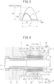
- a hydraulic hammering device that has a cushioning mechanism including a pushing piston 104 and a damping piston 105 disposed behind the chuck driver bush 113, as illustrated in FIG. 12 , is also used.
- a hydraulic pump P is connected as a fluid supply source, hydraulic fluid from the hydraulic pump P is supplied to a pushing chamber 141 so as to provide the pushing piston 104 with a propulsive force, and hydraulic fluid from the hydraulic pump P is supplied to a damping chamber 151 so as to provide the damping piston 105 with a propulsive force.
- the pushing chamber 141 and the damping chamber 151 communicate with each other by way of a fluid feeding hole 152.
- an accumulator 164 is disposed between the cushioning mechanism and the hydraulic pump P.
- the reflected energy Er transmitted from the shank rod 102 to the chuck driver bush 113 is cushioned by retraction of the pushing piston 4 and the damping piston 5.
- Retraction kinetic energy of the pushing piston 104 and damping piston 105 (that is, the reflected energy Er) is eventually accumulated in the accumulator 164 as hydraulic fluid.
- the pushing piston 104 and the damping piston 105 acquire propulsive forces from hydraulic fluid discharged from the hydraulic pump P and hydraulic fluid accumulated in the accumulator 164 due to the cushioning action.
- the rock drill main body 100 which temporarily retracted due to the reflected energy Er from the bedrock R, advances until reaching a predetermined striking position (a state in which the bit 21 comes into contact with the bedrock R) by the time a next strike is performed.
- a predetermined striking position a state in which the bit 21 comes into contact with the bedrock R
- the pushing piston 104 and the damping piston 105 advance more rapidly than the rock drill main body 100 and reach an advancing stroke end of the damping piston 105.
- the pushing piston 104 separating from the damping piston 105, advances and brings the bit 21 into contact with the bedrock R by means of the transmission members.
- the rock drill main body 100 also advanced, and, when the rock drill main body 100 has advanced by a predetermined distance by the time a next strike is performed by the striking mechanism 103, the pushing piston 104 begins to receive a reaction force of the propulsive force F1 of the rock drill main body 100 from the bedrock R.
- the respective propulsive forces F1, F4, and F5 of the rock drill main body 100, the pushing piston 104, and the damping piston 105 satisfy a relation F4 ⁇ F1 ⁇ F5.
- the pushing piston 104 and the damping piston 105 are at positions (hereinafter, referred to as "regular striking positions") where, because of the above relation, a reactive force F1 has caused the pushing piston 104 to retract and come into contact with the damping piston 105 and the damping piston 105 stops at an advancing stroke end and the bit 21 is brought to a state of being in contact with the bedrock R, the striking mechanism 103 performs the next strike.
- a drilling operation is performed by repeating the above strokes.
- the regular striking positions are set so as to be in a positional relation for which, when the striking piston 131 advances and strikes a blow on the rear end of the shank rod 102, blow energy is transmitted most efficiently.
- the cushioning mechanism exerts cushioning action by converting reflected energy to kinetic energy of the pushing piston and the damping piston and subsequently accumulating the converted energy in the accumulator as hydraulic fluid, and, subsequently, the hydraulic fluid accumulated in the accumulator is discharged and, after being converted to kinetic energy of the pushing piston and the damping piston, is transmitted to the rod as reflected energy again.
- the above mechanism including a series of actions is literally cushioning action and may be considered to be sufficiently effective in the sense that damage to the rock drill main body due to reflected energy is suppressed.
- blow output blow energy per blow, and the number of blows per unit time
- Approaches for achieving high output power include a measure of increasing the blow energy per blow, a measure of increasing the number of blows, and a case of performing both measures collectively.
- an increase in the blow energy per blow causes reflected energy to be also increased, there is a risk that, when using the above-described conventional cushioning mechanism, reflected energy accumulated in the accumulator as hydraulic fluid is resultantly returned to the rod side again as it is and the increased reflected energy damages the transmission members, such as a rod and a sleeve.
- the above-described conventional cushioning mechanism has a to-be-solved problem left unsolved for suppressing damage to both the rock drill main body and the transmission members when output power of the striking mechanism is to be improved.
- an object of the present invention is to provide a hydraulic hammering device that is capable of sufficiently transmitting blow energy of a striking piston to bedrock while further strengthening the cushioning action and suppressing damage to both a rock drill main body and transmission members.
- a hydraulic hammering device including: a transmission member configured to transmit a propulsive force toward a crushing target side to a tool; a hammering mechanism configured to strike a blow on a rear portion of the transmission member; a pushing piston disposed immediately behind the transmission member, the pushing piston having a smaller propulsive force than a propulsive force of a device main body of the hydraulic hammering device; a damping piston positioned behind the
- the damping piston having a greater propulsive force than the propulsive force of the device main body of the hydraulic hammering device; a pushing chamber configured to be supplied with hydraulic fluid from a fluid supply source to provide the pushing piston with the smaller propulsive force; a damping chamber configured to be supplied with hydraulic fluid from a fluid supply source to provide the damping piston with the greater propulsive force; a drain circuit configured to discharge a leakage of hydraulic fluid from a location of sliding contact between the pushing piston and the damping piston to a tank; a direction-restrictor provided in a high-pressure circuit between the damping chamber and the pushing chamber, and the fluid supply source, the direction restrictor being configured to restrict an outflow of hydraulic fluid from the damping chamber side and the pushing chamber side to the fluid supply source side, while allowing an inflow of hydraulic fluid from the fluid supply source side to the damping chamber side and the pushing chamber side; and a throttle provided in the drain circuit.
- the hydraulic hammering device when the striking mechanism strikes a blow on the tool by means of the transmission member, the tool penetrates and crushes a crushing target by means of blow energy of the strike. Since reflected energy at this time is transmitted from the tool to the hydraulic hammering device by way of the transmission member, the hydraulic hammering device temporarily retracts due to the reflected energy and, after the hydraulic hammering device has advanced by means of a propulsive force provided to the device main body, the striking mechanism performs a next strike.
- hydraulic fluid in the pushing chamber and the damping chamber has an "outflow" thereof to the fluid supply source side restricted by the direction-restricting means.
- the pushing piston and the damping piston may exert respective predetermined propulsive forces without delay because, the state of hydraulic fluid supplied to the damping chamber side and the pushing chamber side from the fluid supply source is maintained (allowed) by the direction-restricting means.
- the cushioning mechanism of the hydraulic hammering device according to the one aspect of the present invention is a mechanism exerting damping action.
- the hydraulic hammering device since the hydraulic hammering device according to the one aspect of the present invention enables the amount of energy returned to the transmission member to be reduced by means of the cushioning mechanism exerting damping action, it is possible to reduce damage to the transmission member, and the hydraulic hammering device is suitable for, in particular, a striking mechanism capable of delivering a high blow energy.
- the cushioning mechanism of the hydraulic hammering device may always maintain cushioning action properly because the response speed of the direction-restricting means is sufficiently high. For this reason, it is possible to reduce damage to the rock drill main body in a stable manner, and the cushioning mechanism is suitable for, in particular, a striking mechanism capable of delivering a large number of blows.
- the pushing piston and the damping piston advance to predetermined positions (that is, regular striking positions) rapidly and, while the bit is in a state of being in contact with the bedrock, a next strike is performed.
- predetermined positions that is, regular striking positions
- blow energy of the striking piston may be transmitted to the bedrock.
- the hydraulic hammering device is capable of sufficiently transmitting blow energy of a striking piston to bedrock while further strengthening the cushioning action and suppressing damage to both a rock drill main body and transmission members.
- a shank rod 2 is inserted into a front end section of a rock drill main body 1 and a striking mechanism 3 for delivering a blow to the shank rod 2 is disposed behind the shank rod 2.
- a rod 22 having a bit 21 for drilling attached thereto is connected to the shank rod 2 by means of a sleeve 23.
- the rock drill main body 1 includes a chuck driver 12 that provides rotation to the shank rod 2 through a chuck 11.
- a chuck driver bush 13 that comes into contact with a large diameter section rear end 2a of the shank rod 2 is held slidably in the forward and backward directions inside the chuck driver 12.
- a pushing piston 4 and a damping piston 5 are disposed behind the chuck driver bush 13 and form a cushioning mechanism.
- the damping piston 5 is a circular cylindrical piston on the front and the rear of which in the longitudinal direction a front end face 50e and a rear end face 50f are formed, respectively, as illustrated in FIG. 3 .
- the damping piston 5 has an outer large diameter section 50a and an outer small diameter section 50b on the outer peripheral surface of the circular cylindrical shape of the damping piston 5 and, in conjunction therewith, has an inner large diameter section 50c and an inner small diameter section 50d on the inner peripheral surface of the circular cylindrical shape of the damping piston 5.
- a middle step section 14 and a rear step section 15 are formed on the rock drill main body 1.
- the damping piston 5 is held movable in the forward and backward directions between the middle step section 14 and the rear step section 15.
- the damping piston 5 has the outer large diameter section 50a and the outer small diameter section 50b coming into sliding contact with an inner large diameter section 14a on the side on which the middle step section 14 is formed and an inner small diameter section 15a on the side on which the rear step section 15 is formed, respectively.
- the damping piston 5 has, as communication holes making the outer diameter side and the inner diameter side thereof communicate with each other, a drain hole 53a, a fluid feeding hole 52, and a drain hole 53b formed in this order from the front to the rear.
- An annular pushing chamber 41 is formed on the inner diameter side of the fluid feeding hole 52, and, with the pushing chamber 41 as a boundary, the front side and the rear side serve as the above-described inner large diameter section 50c and the above-described inner small diameter section 50d, respectively.
- a seal 54a and a seal 54b are formed on the inner peripheral surface on the front side of the drain hole 53a and on the inner peripheral surface on the rear side of the drain hole 53b, respectively
- the pushing piston 4 is, as illustrated in FIG.3 , a flanged circular cylindrical piston and has, on the outer peripheral surface of the circular cylindrical shape thereof, an outer large diameter section 40a, an outer medium diameter section 40b, and an outer small diameter section 40c formed in this order from the front to the rear.
- a front end face 40d and a middle end face 40e are formed on the front side of the outer large diameter section 40a, which has a flange shape, and on the rear side of the flange shape, respectively.
- a front step section 16 is formed on the rock drill main body 1, and the pushing piston 4 is held so that the outer large diameter section 40a thereof, which has a flange shape, is movable in the forward and backward directions between the front step section 16 and the front end face 50e of the damping piston 5.
- the pushing piston 4 and the damping piston 5 have the medium diameter section 40b and the inner large diameter section 50c coming into sliding contact with each other and the small diameter section 40c and the inner small diameter section 50d coming into sliding contact with each other.
- the small diameter section and the large diameter section are formed on a front side portion and a rear side portion of the inner peripheral surface of the pushing piston 4 of the present embodiment, respectively, the small diameter section and the large diameter section are shapes for avoiding interference with a striking piston 31 and do not have any influence on a cushioning function.
- a drain port 18a is formed at a position facing the drain hole 53a of the damping piston 5, as illustrated in FIG. 2 .
- a seal 19a is formed on the front side of the drain port 18a.
- a pushing port 17 is formed on the inner small diameter section 15a of the inner peripheral surface of the rock drill main body 1, at a position facing the fluid feeding hole 52 of the damping piston 5.
- a drain port 18b is formed at a position facing the drain hole 53b, and a seal 19b is formed on the rear side of the drain port 18b.
- a damping chamber 51 is formed at the boundary between the inner large diameter section 14a and the inner small diameter section 15a.
- a hydraulic pump P is connected by way of a high-pressure circuit 6, and, in conjunction therewith, a tank T is connected by way of a drain circuit 7.
- one end of the high-pressure circuit 6 is connected to the hydraulic pump P and the other end splits into a pushing passage 61 and a damping passage 62, and the pushing passage 61 and the damping passage 62 are connected to the pushing port 17 and the damping chamber 51, respectively.
- a check valve 8 is interposed in the pushing passage 61.
- the check valve 8 is provided as a direction-restricting means for, while allowing an inflow of hydraulic fluid from the side on which the hydraulic pump P is placed to the side on which the pushing port 17 is formed, restricting an outflow of hydraulic fluid from the side on which the pushing port 17 is formed to the side on which the hydraulic pump P is placed.
- a check valve 9 is interposed in the damping passage 62.
- the check valve 9 is provided as a direction-restricting means for, while allowing an inflow of hydraulic fluid from the side on which the hydraulic pump P is placed to the side on which the damping chamber 51 is formed, restricting an outflow of hydraulic fluid from the side on which the damping chamber 51 is formed to the side on which the hydraulic pump is placed.
- the tank T is connected to one end of the drain circuit 7, and the other end of the drain circuit 7 splits into a drain passage 71a and a drain passage 71b.
- the drain passage 71a and the drain passage 71b are connected to the drain port 18a and the drain port 18b, respectively.
- a variable throttle 10 is interposed in the drain circuit 7.
- the pushing piston 4 and the damping piston 5 retract in one body relatively to the rock drill main body 1. Locations of sliding contact at this time are between the inner peripheral surfaces (the inner large diameter section 14a and the inner small diameter section 15a) of the rock drill main body 1 and the outer peripheral surfaces (the outer large diameter section 50a and the outer small diameter section 50b) of the damping piston 5.
- variable throttle 10 is interposed in the drain circuit 7 and controls the upper limit of the amount of leakage of the leaking hydraulic fluid, that is, the amount of consumed fluid in the damper.
- the pushing piston 4 retracts relatively to the damping piston 5 and, in conjunction therewith, the damping piston 5 retracts relatively to the rock drill main body 1.
- Locations of sliding contact at this time are between the outer peripheral surfaces (the outer medium diameter section 40b and the outer small diameter section 40c) of the pushing piston 4 and the inner peripheral surfaces (the inner large diameter section 50c and the inner small diameter section 50d) of the damping piston 5 and between the inner peripheral surfaces (the inner large diameter section 14a and the inner small diameter section 15a) of the rock drill main body 1 and the outer peripheral surfaces (the outer large diameter section 50a and the outer small diameter section 50b) of the damping piston 5.
- variable throttle 10 is interposed in the drain circuit 7 and controls the upper limit of the amount of leakage of the leaking hydraulic fluid, that is, the amount of consumed fluid in the damper.
- the pushing piston 4 retracts first, the middle end face 40e comes into contact with the front end face 50e, and, eventually, the pushing piston 4 and the damping piston 5 retract in one body.
- the cushioning propulsive force F4 1 is greater than the cushioning propulsive force F4 0 , initial cushioning action performed by the pushing piston 4 is sufficiently effective.
- the cushioning mechanism of the present embodiment has an advantageous effect of enabling striking speed to be reduced to a slower speed and noise to be thereby suppressed to a lower level than the conventional cushioning mechanism described using FIG. 12 .
- the cushioning mechanism of the present embodiment enables the pushing piston 4 and the damping piston 5 to always exert cushioning action accompanied by damping action in a stable manner, damage to the rock drill main body 1, a tool, and transmission members may be reduced.
- the cushioning stroke means a stroke in which the reflected energy Er from the bedrock R is transmitted and the pushing piston 4 and the damping piston 5, while retracting, exert cushioning action accompanied by damping action.
- the rock drill main body 1 which temporarily retracted due to the reflected energy Er from the bedrock R, advances until reaching a state in which the bit 21 comes into contact with the bedrock R, that is, to a predetermined striking position, by the time a next strike is performed.
- the pushing piston 4 and the damping piston 5 advance more rapidly than the rock drill main body 1 and, after advancing to an advancing stroke end of the damping piston 5, that is, a reference position at which the front end face 50e comes into contact with the middle step section 14, stops.
- the pushing piston 4, separating from the damping piston 5, advances and brings the bit 21 into contact with the bedrock R by means of the transmission members.
- the rock drill main body 1 also advances, and, subsequently, the rock drill main body 1, which is in a state in which the damping piston 5 is in contact with the front end face 14 of the rock drill main body 1, catches up with and comes into contact with the pushing piston by the time a next strike is performed by the striking mechanism 3.
- the striking mechanism 3 performs a next strike in a state in which a reactive force F1 causes the pushing piston 4 to retract and come into contact with the damping piston 5 and the damping piston 5 stops at the advancing stroke end (i.e. the rock drill main body 1, the pushing piston 4, and the damping piston 5 are at the regular striking positions), and the bit 21 is in contact with the bedrock R, and the propulsive force F1 is acting.
- the pushing piston 4 rapidly advances from the regular striking position and brings the bit 21 into contact with the bedrock R by means of the transmission members. This operation enables the blow energy of the striking piston 31 to be transmitted to the bedrock R.
- a stroke in which, after the cushioning stroke, the pushing piston 4 and the damping piston 5 advance and bring the bit 21 to a state of being in contact with the bedrock R is referred to as an advancing stroke.
- the damping chamber 51 and the pushing chamber 41 substantially excel in responsiveness because of, while having hydraulic fluid therein restricted to flow out to the side on which the hydraulic pump P is placed by the check valves 9 and 8, respectively, being always supplied with hydraulic fluid from the side on which the hydraulic pump P is placed, which causes the advancing stroke to be performed rapidly.
- FIGS. 4A and 4B are diagrams schematically illustrating a relationship between a stroke of the damping piston 5 and pressure in the damping chamber 51 in the cushioning stroke and illustrates a case of the conventional cushioning mechanism described in FIG. 12 and a case of the cushioning mechanism of the present embodiment in FIGS. 4A and 4B , respectively, in a comparative manner.
- a stroke of the conventional damping piston 105 and a stroke of the damping piston 5 of the present embodiment are indicated by Sd1 and Sd2, respectively, and pressure in the conventional damping chamber 151 and pressure in the damping chamber 51 of the present embodiment are indicated by Pd1 and Pd2, respectively.
- the pressure Pd2 is a hydraulic pressure while the damping piston 5 is retracting, and, since hydraulic fluid in the damping chamber 51, which has nowhere to go because being restricted by the check valve 9, has its pressure raised due to passage resistance when leaking from clearance at the locations of sliding contact and a relation Pd2 > Pd1 thus holds, a relation Sd2 ⁇ Sd1 holds. Therefore, it is clear that the retracting stroke of the damping piston 5 of the present embodiment is shorter than the retracting stroke of the conventional damping piston 105.
- the pressure in the damping chamber 51 of the present embodiment changes from Pd2 to Pd1 and vice versa between the cushioning stroke and the advancing stroke satisfying Pd2 > Pd1, hysteresis occurs, and the hysteresis becomes damping energy.
- the damping energy Ed is equivalent to the hatched portion in FIG. 4B .
- the cushioning mechanism of the present embodiment enables energy returned to transmission members to be substantially reduced. For this reason, the cushioning mechanism of the present embodiment contributes to load reduction on the transmission members and, in particular, produces a greater effect as blow energy increases.
- FIG. 5 is a diagram schematically illustrating a relationship between a stroke of the damping piston 5 and cushioning period of the damping chamber 51 and illustrates a case (a) of the conventional cushioning mechanism described in FIG. 12 and a case (b) of the cushioning mechanism of the present embodiment in a comparative manner.
- a stroke of the conventional damping piston 105 illustrated in FIG. 12 and a stroke of the damping piston 5 of the present embodiment are indicated by Sd1 and Sd2, respectively
- a cushioning period of the conventional damping mechanism and a cushioning period of the damping mechanism of the present embodiment are indicated by t1 and t2, respectively.
- the retracting stroke of the damping piston 5 of the present embodiment is shorter than the retracting stroke of the conventional damping piston 105 as Sd2 ⁇ Sd1, it can be seen that the cushioning period is also reduced as t2 ⁇ t1, as illustrated in FIG. 5 .
- a short retracting stroke of the damping piston 5 enables a rapid transition to a succeeding advancing stroke. Therefore, the cushioning mechanism of the present embodiment may complete both the cushioning stroke and the advancing stroke in a short period of time and, in particular, produces a greater effect as the number of blows per unit time increases.
- the hydraulic hammering device according to the present invention is not limited to the above-described first embodiment. Hereinafter, other embodiments will be further described.
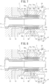
- FIG. 6 illustrates a second embodiment of the present invention, and the second embodiment has the same configuration as the above-described first embodiment except a difference in that a second throttle 63 is added to a high-pressure circuit 6.
- the amount of flow rate adjustment (the amount of throttling) by the second throttle 63 is set smaller than the amount of flow rate adjustment by a variable throttle 10.
- check valves 8 and 9 are interposed as direction-restricting means, the check valves 8 and 9 having a very little internal leakage cannot be avoided because of the nature of hydraulic equipment, it is difficult to completely prevent hydraulic fluid from flowing out.
- FIG. 7 illustrates a third embodiment of the present invention, and the third embodiment has the same configuration as the above-described second embodiment except a difference in that an accumulator 64 is added to a high-pressure circuit 6 between check valves 8 and 9 and a second throttle 63 that are interposed in the high-pressure circuit 6.
- interposing the second throttle 63 in the high-pressure circuit 6 as a countermeasure against an outflow in the high-pressure circuit 6 is effective.
- the second throttle 63 interposed in the high-pressure circuit 6 also works as resistance against supply of hydraulic fluid from the side on which a hydraulic pump P is placed to the sides on which a pushing chamber 41 and a damping chamber 51 are formed.
- the accumulator 64 enables such pulsation to die out quickly.
- a striking mechanism capable of delivering a large number of blows a next pulsation occurring before a current pulsation is damped doubles the amplitude of the pulsations and the doubled pulsations damage equipment, disposition of the accumulator 64 enables the pulsation problem to be solved.
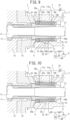
- FIG. 8 illustrates a fourth embodiment of the present invention, and the fourth embodiment has the same configuration as the above-described third embodiment except a difference in that a throttle 91 is interposed in place of a check valve 9 as a direction-restricting means in a high-pressure passage 62.
- the wavelength of generated reflected waves shortens and the length of a time period during which the reflected waves act on a cushioning mechanism also shortens.
- the cushioning mechanism is required to exert sufficient cushioning action in a short period of time and, to fulfill the requirement, required to increase the response speed of the direction-restricting means.
- a throttle is employable as a direction-controlling means in addition to a check valve
- a throttle excels a check valve in the response speed of cushioning action.
- a check valve excels a throttle in advancing speed after the cushioning stroke has turned to the advancing stroke. Therefore, in the fourth embodiment, the throttle 91 is employed as a direction-controlling means in a damping passage 62, and a check valve 8 is employed as a direction-controlling means in a pushing passage 61.
- the amounts of adjustments of the respective throttles in the fourth embodiment have a relationship such that the amount of adjustment of the throttle 91 as a direction-controlling means is smaller than the amount of adjustment of a variable throttle 10 in a drain circuit 7 that is smaller than the amount of adjustment of a second throttle 63.
- FIG. 9 illustrates a fifth embodiment of the present invention, and the fifth embodiment has the same configuration as the above-described third embodiment except a difference in that, a high-pressure passage 6 branches into branch passages 65a and 65b, and the branch passage 65a and 65b are connected to a damping chamber 51 and a pushing port 17, respectively, and a check valve 81 is interposed as a direction-restricting means at a position on the side on which a pump P is placed beyond a branch point between the two branch passages 65a and 65b.
- a check valve 81 is interposed as a direction-restricting means at a position on the side on which a pump P is placed beyond a branch point between the two branch passages 65a and 65b.
- FIG. 10 illustrates a sixth embodiment of the present invention, and the sixth embodiment has the same configuration as the above-described fifth embodiment except a difference in that a damping chamber 51 and a pushing port 17 are combined into a cushioning chamber 55 and a high-pressure circuit 6 is connected to the cushioning chamber 55 without branching.
- a damping chamber 51 and a pushing port 17 are combined into a cushioning chamber 55 and a high-pressure circuit 6 is connected to the cushioning chamber 55 without branching.
- fifth and sixth embodiments are embodiments for, by combining hydraulic systems that are, in the other embodiments, individually provided to the respective ones of a pushing piston 4 and a damping piston 5 into one hydraulic system, achieving a simplification in a configuration and a reduction in cost.
- sharing hydraulic systems causes influence of pulsation of hydraulic fluid occurring caused by the operations of the respective ones of the pushing piston 4 and the damping piston 5 to be also shared.
- the hydraulic systems are shared, it is impossible to, as in the fourth embodiment, determine specifications of direction-restricting means according to respective characteristics of the pushing piston 4 and the damping piston 5.
Landscapes
- Engineering & Computer Science (AREA)
- Mining & Mineral Resources (AREA)
- Mechanical Engineering (AREA)
- Geology (AREA)
- Life Sciences & Earth Sciences (AREA)
- General Life Sciences & Earth Sciences (AREA)
- Geochemistry & Mineralogy (AREA)
- Fluid Mechanics (AREA)
- Physics & Mathematics (AREA)
- Automation & Control Theory (AREA)
- Environmental & Geological Engineering (AREA)
- Earth Drilling (AREA)
- Percussive Tools And Related Accessories (AREA)
- Operation Control Of Excavators (AREA)
Claims (5)
- Hydraulische Schlagvorrichtung, umfassend:- ein Übertragungselement (2), das konfiguriert ist, um eine Antriebskraft in Richtung einer Brechzielseite auf ein Werkzeug zu übertragen;- einen Schlagmechanismus, der konfiguriert ist, um einen Schlag auf einen hinteren Abschnitt des Übertragungselements (2) zu schlagen;- einen Schubkolben (4), der unmittelbar hinter dem Übertragungselement (2) angeordnet ist, wobei der Schubkolben (4) eine geringere Antriebskraft als eine Antriebskraft eines Vorrichtungshauptkörpers (1) der hydraulischen Schlagvorrichtung aufweist;- einen Dämpfungskolben (5), der hinter dem Schubkolben (4) positioniert und angeordnet ist, sodass er gegen den Schubkolben (4) in Vorwärts- und Rückwärtsrichtung hin- und her gleitet, wobei der Dämpfungskolben (5) eine größere Antriebskraft aufweist als die Antriebskraft des Vorrichtungshauptkörpers (1) der hydraulischen Schlagvorrichtung;- eine Schubkammer (41), die konfiguriert ist, um mit Hydraulikfluid von einer Fluidversorgungsquelle (P) versorgt zu sein, um den Schubkolben (4) mit der kleineren Antriebskraft vorzusehen;- eine Dämpfungskammer (51), die konfiguriert ist, um mit Hydraulikfluid von einer Fluidversorgungsquelle (P) versorgt zu sein, um den Dämpfungskolben (5) mit der größeren Antriebskraft zu versorgen;- einen Ablaufkreis (7), der konfiguriert ist, um eine Leckage von Hydraulikfluid von einer Stelle mit gleitendem Kontakt zwischen dem Schubkolben (4) und dem Dämpfungskolben (5) zu einem Tank (T) abzuleiten;dadurch gekennzeichnet, dass die hydraulische Schlagvorrichtung ferner aufweist:- einen Richtungsbegrenzer (8, 9), der in einem Hochdruckkreis (6) zwischen der Dämpfungskammer (51) und der Schubkammer (41), und der Fluidversorgungsquelle (P) vorgesehen ist, wobei der Richtungsbegrenzer konfiguriert ist, um einen Ausfluss von Hydraulikfluid von der Dämpfungskammerseite und der Schubkammerseite zur Fluidversorgungsquellenseite zu beschränken, während ein Einströmen von Hydraulikfluid von der Fluidversorgungsquellenseite zur Dämpfungskammerseite und der Schubkammerseite ermöglicht ist; und- eine Drossel (10), die in dem Ablaufkreis (7) vorgesehen ist.
- Hydraulische Schlagvorrichtung nach Anspruch 1, wobei- der Vorrichtungshauptkörper (1) einen ersten Abflussanschluss (18a) und einen zweiten Abflussanschluss (18b) an einer inneren peripheren Oberfläche des Vorrichtungshauptkörpers (1) aufweist, die einer äußeren peripheren Oberfläche des Dämpfungskolbens (5) gegenüberliegt, wobei der erste Abflussanschluss (18a) in einer axialen Richtung nach vorne von der Dämpfungskammer (51) getrennt ist und der zweite Anschluss (18b) in der axialen Richtung nach hinten von der Schubkammer (41) getrennt ist,- ein Ende des Ablaufkreises (7) mit einem Tank (T) verbunden ist und ein anderes Ende des Ablaufkreises (7) sich in einen ersten Ablaufkanal (71a) und einen zweiten Ablaufkanal (71b) aufteilt, und- der erste Abflusskanal (71a) mit dem ersten Abflussanschluss (18a) verbunden ist und der zweite Abflusskanal (71b) mit dem zweiten Abflussanschluss (18b) verbunden ist.
- Hydraulische Schlagvorrichtung nach Anspruch 1 oder 2,- ferner umfassend eine zweite Drossel (63), die in einem Hochdruckkreis (6) zwischen dem Richtungsbegrenzer (8, 9) und der Fluidversorgungsquelle (P) vorgesehen ist, wobei- ein Betrag der Durchflussrateneinstellung durch die zweite Drossel (63) eingestellt ist, um niedriger zu sein als ein Betrag der Durchflussrateneinstellung durch die Drossel (10), die in dem Ablaufkreis (7) vorgesehen ist.
- Hydraulische Schlagvorrichtung nach Anspruch 3, die ferner einen Akkumulator aufweist, der in einem Hochdruckkreis (6) zwischen dem Richtungsbegrenzer (8, 9) und der zweiten Drossel (63) vorgesehen ist.
- Hydraulische Schlagvorrichtung nach einem der Ansprüche 1 bis 4, wobei- der Richtungsbegrenzer (8, 9) einen ersten Richtungsbegrenzer (9) und einen zweiten Richtungsbegrenzer (9) aufweist, die jeweils in einem ersten Hochdruckkreis zwischen der Dämpfungskammer (51) und der Fluidversorgungsquelle (P) und einem zweiten Hochdruckkreis zwischen der Schubkammer (41) und der Fluidversorgungsquelle (P) vorgesehen sind, und- der zweite Richtungsbegrenzer (8) an der Schubkammerseite ein Rückschlagventil (8, 81) ist, und der erste Richtungsbegrenzer (9) an der Dämpfungskammerseite eine Drossel (9, 91) oder ein Rückschlagventil (9) ist.
Applications Claiming Priority (2)
| Application Number | Priority Date | Filing Date | Title |
|---|---|---|---|
| JP2015251520 | 2015-12-24 | ||
| PCT/JP2016/087916 WO2017110793A1 (ja) | 2015-12-24 | 2016-12-20 | 油圧打撃装置 |
Publications (3)
| Publication Number | Publication Date |
|---|---|
| EP3395504A1 EP3395504A1 (de) | 2018-10-31 |
| EP3395504A4 EP3395504A4 (de) | 2019-02-20 |
| EP3395504B1 true EP3395504B1 (de) | 2023-05-10 |
Family
ID=59090354
Family Applications (1)
| Application Number | Title | Priority Date | Filing Date |
|---|---|---|---|
| EP16878682.0A Active EP3395504B1 (de) | 2015-12-24 | 2016-12-20 | Hydraulische hammervorrichtung |
Country Status (7)
| Country | Link |
|---|---|
| US (1) | US11034010B2 (de) |
| EP (1) | EP3395504B1 (de) |
| JP (2) | JP6571797B2 (de) |
| KR (1) | KR102056992B1 (de) |
| CN (2) | CN119036376A (de) |
| FI (1) | FI3395504T3 (de) |
| WO (1) | WO2017110793A1 (de) |
Families Citing this family (7)
| Publication number | Priority date | Publication date | Assignee | Title |
|---|---|---|---|---|
| KR102660561B1 (ko) * | 2019-09-10 | 2024-04-24 | 듀블린 캄파니, 엘엘씨 | 워시파이프 시스템과 방법 |
| JP7390952B2 (ja) * | 2020-03-25 | 2023-12-04 | 古河ロックドリル株式会社 | 油圧ブレーカ |
| JP7758504B2 (ja) * | 2021-08-18 | 2025-10-22 | 古河ロックドリル株式会社 | 油圧ブレーカ用バルブアジャスタ |
| CN115095280B (zh) * | 2022-07-15 | 2024-12-20 | 中交二公局第七工程有限公司 | 一种公路护栏立柱钻孔、打桩一体化机器人 |
| EP4599988A1 (de) * | 2022-10-05 | 2025-08-13 | Furukawa Rock Drill Co., Ltd. | Hydraulische hammervorrichtung |
| CN116558865B (zh) * | 2023-07-05 | 2023-09-22 | 徐州徐工基础工程机械有限公司 | 液压凿岩机缓冲装置模拟试验装置 |
| CN118148980B (zh) * | 2024-05-10 | 2024-07-02 | 烟台乐匠液压机械有限公司 | 一种具有高速换向阀的旋转冲击破碎装置 |
Family Cites Families (23)
| Publication number | Priority date | Publication date | Assignee | Title |
|---|---|---|---|---|
| DE1703061C3 (de) * | 1968-03-27 | 1974-02-14 | Fried. Krupp Gmbh, 4300 Essen | Hydraulisch betriebener Schubkolbenmotor |
| DE2716701C3 (de) * | 1977-04-15 | 1983-01-05 | Koehring Gmbh, 2086 Ellerau | Rammgerät |
| JPS57178092A (en) * | 1981-04-25 | 1982-11-02 | Okada Sakuganki Kk | Oil pressure type rock drilling machine |
| FR2647870B1 (fr) * | 1989-06-06 | 1991-09-06 | Eimco Secoma | Appareil de percussion hydraulique avec dispositif d'amortissement des ondes de choc en retour |
| JP3483015B2 (ja) * | 1995-10-16 | 2004-01-06 | 古河機械金属株式会社 | 油圧打撃装置の緩衝機構 |
| JP3793904B2 (ja) * | 1997-06-19 | 2006-07-05 | 古河機械金属株式会社 | さく岩機の打撃力制御機構 |
| JP3824112B2 (ja) * | 1997-07-18 | 2006-09-20 | 古河機械金属株式会社 | 油圧打撃装置の緩衝機構 |
| JP4514900B2 (ja) * | 2000-05-31 | 2010-07-28 | 古河機械金属株式会社 | 油圧打撃装置の緩衝機構 |
| JP4463381B2 (ja) * | 2000-06-01 | 2010-05-19 | 古河機械金属株式会社 | 油圧さく岩機のダンパ圧力制御装置 |
| CN1390659A (zh) * | 2002-07-16 | 2003-01-15 | 太原重型机械学院 | 电液锤打击控制系统 |
| SE529416C2 (sv) * | 2005-12-22 | 2007-08-07 | Atlas Copco Rock Drills Ab | Dämpanordning jämte borrmaskin inkluderande en dylik dämpanordning |
| CN201306333Y (zh) * | 2008-09-16 | 2009-09-09 | 上海工程技术大学 | 智能型液压冲击器 |
| SE533344C2 (sv) * | 2009-01-16 | 2010-08-31 | Atlas Copco Rock Drills Ab | Dämpningsanordning för slagverk, slagverk och borrmaskin |
| SE535068C2 (sv) * | 2010-04-01 | 2012-04-03 | Atlas Copco Rock Drills Ab | Bergborrmaskin och användning därav för att förhindra uppkomst och spridning av kavitationsbubblor |
| RU2456424C1 (ru) * | 2010-12-07 | 2012-07-20 | Государственное образовательное учреждение высшего профессионального образования "Орловский государственный технический университет" (ОрелГТУ) | Гидравлическое устройство ударного действия |
| CN202251621U (zh) * | 2011-09-16 | 2012-05-30 | 李华 | 一种自动调节缓冲力值的液压缓冲器 |
| CN103191800A (zh) * | 2012-01-06 | 2013-07-10 | 范公奇 | 液压缓冲装置及具有该液压缓冲装置的圆锥破碎机 |
| CN202788599U (zh) * | 2012-01-20 | 2013-03-13 | 中船重工中南装备有限责任公司 | 一种凿岩机的凿岩控制系统 |
| CN202531014U (zh) * | 2012-01-20 | 2012-11-14 | 中船重工中南装备有限责任公司 | 一种液压凿岩机的可调凿岩控制系统 |
| SE536758C2 (sv) * | 2012-11-28 | 2014-07-15 | Atlas Copco Rock Drills Ab | Slagverk till en hydraulisk bergborrmaskin, förfarande för drift av ett slagverk och hydraulisk bergborrmaskin inkluderande ett slagverk |
| EP2873489B1 (de) * | 2013-11-13 | 2018-10-24 | Sandvik Mining and Construction Oy | Stoßvorrichtung und Verfahren zur Demontage dafür |
| SE537838C2 (sv) | 2014-02-14 | 2015-11-03 | Atlas Copco Rock Drills Ab | Dämpningsanordning för slagverk, slagverk och bergborrmaskin |
| CN204646830U (zh) * | 2015-03-13 | 2015-09-16 | 辽宁瑞丰专用车制造有限公司 | 一种凿岩机的液压系统 |
-
2016
- 2016-12-20 EP EP16878682.0A patent/EP3395504B1/de active Active
- 2016-12-20 FI FIEP16878682.0T patent/FI3395504T3/fi active
- 2016-12-20 US US16/065,325 patent/US11034010B2/en active Active
- 2016-12-20 WO PCT/JP2016/087916 patent/WO2017110793A1/ja not_active Ceased
- 2016-12-20 CN CN202411301887.8A patent/CN119036376A/zh active Pending
- 2016-12-20 KR KR1020187013277A patent/KR102056992B1/ko active Active
- 2016-12-20 JP JP2017558146A patent/JP6571797B2/ja active Active
- 2016-12-20 CN CN201680073392.1A patent/CN108367419A/zh active Pending
-
2019
- 2019-08-07 JP JP2019145555A patent/JP6792034B2/ja active Active
Also Published As
| Publication number | Publication date |
|---|---|
| CN119036376A (zh) | 2024-11-29 |
| US20190210205A1 (en) | 2019-07-11 |
| CN108367419A (zh) | 2018-08-03 |
| EP3395504A1 (de) | 2018-10-31 |
| JP6571797B2 (ja) | 2019-09-04 |
| JP6792034B2 (ja) | 2020-11-25 |
| WO2017110793A1 (ja) | 2017-06-29 |
| KR20180067622A (ko) | 2018-06-20 |
| US11034010B2 (en) | 2021-06-15 |
| JP2019188603A (ja) | 2019-10-31 |
| EP3395504A4 (de) | 2019-02-20 |
| KR102056992B1 (ko) | 2019-12-17 |
| FI3395504T3 (fi) | 2023-08-09 |
| JPWO2017110793A1 (ja) | 2018-06-28 |
Similar Documents
| Publication | Publication Date | Title |
|---|---|---|
| EP3395504B1 (de) | Hydraulische hammervorrichtung | |
| CN109414809B (zh) | 双活塞型液压冲击装置 | |
| CN105916634B (zh) | 液压式冲击装置 | |
| US3780621A (en) | Hydraulic fluid actuated percussion tool | |
| CN107848097B (zh) | 液压式冲击装置 | |
| AU2019221107B2 (en) | Rotary-percussive hydraulic drill provided with a control chamber which is permanently connected to a low-pressure accumulator | |
| US20090084257A1 (en) | Hydraulic cylinder having multi-stage snubbing valve | |
| EP2718064B1 (de) | Schlagvorrichtung für eine gesteinszertrümmerungsvorrichtung und verfahren zur steuerung der schlagvorrichtung | |
| JP6470058B2 (ja) | 液圧式打撃装置 | |
| KR102425266B1 (ko) | 액압식 타격장치 | |
| US11697197B2 (en) | Hydraulic rotary-percussive hammer drill provided with a stop piston | |
| EP4599988A1 (de) | Hydraulische hammervorrichtung | |
| US11084155B2 (en) | Hydraulic striking device | |
| KR20180000298A (ko) | 착암기 | |
| JP2018138321A (ja) | 液圧式打撃装置 | |
| KR102015668B1 (ko) | 역순환 천공 해머를 위한 가압된 유체 유동 시스템 및 이를 이용한 해머 |
Legal Events
| Date | Code | Title | Description |
|---|---|---|---|
| STAA | Information on the status of an ep patent application or granted ep patent |
Free format text: STATUS: THE INTERNATIONAL PUBLICATION HAS BEEN MADE |
|
| PUAI | Public reference made under article 153(3) epc to a published international application that has entered the european phase |
Free format text: ORIGINAL CODE: 0009012 |
|
| STAA | Information on the status of an ep patent application or granted ep patent |
Free format text: STATUS: REQUEST FOR EXAMINATION WAS MADE |
|
| 17P | Request for examination filed |
Effective date: 20180621 |
|
| AK | Designated contracting states |
Kind code of ref document: A1 Designated state(s): AL AT BE BG CH CY CZ DE DK EE ES FI FR GB GR HR HU IE IS IT LI LT LU LV MC MK MT NL NO PL PT RO RS SE SI SK SM TR |
|
| AX | Request for extension of the european patent |
Extension state: BA ME |
|
| RIC1 | Information provided on ipc code assigned before grant |
Ipc: B25D 9/26 20060101AFI20190110BHEP Ipc: E21B 1/26 20060101ALI20190110BHEP Ipc: B25D 17/24 20060101ALI20190110BHEP Ipc: E21B 1/02 20060101ALI20190110BHEP Ipc: E21C 27/12 20060101ALI20190110BHEP |
|
| A4 | Supplementary search report drawn up and despatched |
Effective date: 20190117 |
|
| DAV | Request for validation of the european patent (deleted) | ||
| DAX | Request for extension of the european patent (deleted) | ||
| GRAP | Despatch of communication of intention to grant a patent |
Free format text: ORIGINAL CODE: EPIDOSNIGR1 |
|
| STAA | Information on the status of an ep patent application or granted ep patent |
Free format text: STATUS: GRANT OF PATENT IS INTENDED |
|
| INTG | Intention to grant announced |
Effective date: 20230109 |
|
| GRAS | Grant fee paid |
Free format text: ORIGINAL CODE: EPIDOSNIGR3 |
|
| GRAA | (expected) grant |
Free format text: ORIGINAL CODE: 0009210 |
|
| STAA | Information on the status of an ep patent application or granted ep patent |
Free format text: STATUS: THE PATENT HAS BEEN GRANTED |
|
| RAP3 | Party data changed (applicant data changed or rights of an application transferred) |
Owner name: FURUKAWA ROCK DRILL CO., LTD. |
|
| AK | Designated contracting states |
Kind code of ref document: B1 Designated state(s): AL AT BE BG CH CY CZ DE DK EE ES FI FR GB GR HR HU IE IS IT LI LT LU LV MC MK MT NL NO PL PT RO RS SE SI SK SM TR |
|
| REG | Reference to a national code |
Ref country code: GB Ref legal event code: FG4D |
|
| REG | Reference to a national code |
Ref country code: AT Ref legal event code: REF Ref document number: 1566234 Country of ref document: AT Kind code of ref document: T Effective date: 20230515 Ref country code: CH Ref legal event code: EP |
|
| REG | Reference to a national code |
Ref country code: DE Ref legal event code: R096 Ref document number: 602016079421 Country of ref document: DE |
|
| REG | Reference to a national code |
Ref country code: IE Ref legal event code: FG4D |
|
| P01 | Opt-out of the competence of the unified patent court (upc) registered |
Effective date: 20230515 |
|
| REG | Reference to a national code |
Ref country code: FI Ref legal event code: FGE |
|
| REG | Reference to a national code |
Ref country code: LT Ref legal event code: MG9D |
|
| REG | Reference to a national code |
Ref country code: SE Ref legal event code: TRGR |
|
| REG | Reference to a national code |
Ref country code: NL Ref legal event code: MP Effective date: 20230510 |
|
| REG | Reference to a national code |
Ref country code: AT Ref legal event code: MK05 Ref document number: 1566234 Country of ref document: AT Kind code of ref document: T Effective date: 20230510 |
|
| PG25 | Lapsed in a contracting state [announced via postgrant information from national office to epo] |
Ref country code: PT Free format text: LAPSE BECAUSE OF FAILURE TO SUBMIT A TRANSLATION OF THE DESCRIPTION OR TO PAY THE FEE WITHIN THE PRESCRIBED TIME-LIMIT Effective date: 20230911 Ref country code: NO Free format text: LAPSE BECAUSE OF FAILURE TO SUBMIT A TRANSLATION OF THE DESCRIPTION OR TO PAY THE FEE WITHIN THE PRESCRIBED TIME-LIMIT Effective date: 20230810 Ref country code: NL Free format text: LAPSE BECAUSE OF FAILURE TO SUBMIT A TRANSLATION OF THE DESCRIPTION OR TO PAY THE FEE WITHIN THE PRESCRIBED TIME-LIMIT Effective date: 20230510 Ref country code: ES Free format text: LAPSE BECAUSE OF FAILURE TO SUBMIT A TRANSLATION OF THE DESCRIPTION OR TO PAY THE FEE WITHIN THE PRESCRIBED TIME-LIMIT Effective date: 20230510 Ref country code: AT Free format text: LAPSE BECAUSE OF FAILURE TO SUBMIT A TRANSLATION OF THE DESCRIPTION OR TO PAY THE FEE WITHIN THE PRESCRIBED TIME-LIMIT Effective date: 20230510 |
|
| PG25 | Lapsed in a contracting state [announced via postgrant information from national office to epo] |
Ref country code: RS Free format text: LAPSE BECAUSE OF FAILURE TO SUBMIT A TRANSLATION OF THE DESCRIPTION OR TO PAY THE FEE WITHIN THE PRESCRIBED TIME-LIMIT Effective date: 20230510 Ref country code: PL Free format text: LAPSE BECAUSE OF FAILURE TO SUBMIT A TRANSLATION OF THE DESCRIPTION OR TO PAY THE FEE WITHIN THE PRESCRIBED TIME-LIMIT Effective date: 20230510 Ref country code: LV Free format text: LAPSE BECAUSE OF FAILURE TO SUBMIT A TRANSLATION OF THE DESCRIPTION OR TO PAY THE FEE WITHIN THE PRESCRIBED TIME-LIMIT Effective date: 20230510 Ref country code: LT Free format text: LAPSE BECAUSE OF FAILURE TO SUBMIT A TRANSLATION OF THE DESCRIPTION OR TO PAY THE FEE WITHIN THE PRESCRIBED TIME-LIMIT Effective date: 20230510 Ref country code: IS Free format text: LAPSE BECAUSE OF FAILURE TO SUBMIT A TRANSLATION OF THE DESCRIPTION OR TO PAY THE FEE WITHIN THE PRESCRIBED TIME-LIMIT Effective date: 20230910 Ref country code: HR Free format text: LAPSE BECAUSE OF FAILURE TO SUBMIT A TRANSLATION OF THE DESCRIPTION OR TO PAY THE FEE WITHIN THE PRESCRIBED TIME-LIMIT Effective date: 20230510 Ref country code: GR Free format text: LAPSE BECAUSE OF FAILURE TO SUBMIT A TRANSLATION OF THE DESCRIPTION OR TO PAY THE FEE WITHIN THE PRESCRIBED TIME-LIMIT Effective date: 20230811 |
|
| PG25 | Lapsed in a contracting state [announced via postgrant information from national office to epo] |
Ref country code: SK Free format text: LAPSE BECAUSE OF FAILURE TO SUBMIT A TRANSLATION OF THE DESCRIPTION OR TO PAY THE FEE WITHIN THE PRESCRIBED TIME-LIMIT Effective date: 20230510 |
|
| PG25 | Lapsed in a contracting state [announced via postgrant information from national office to epo] |
Ref country code: SM Free format text: LAPSE BECAUSE OF FAILURE TO SUBMIT A TRANSLATION OF THE DESCRIPTION OR TO PAY THE FEE WITHIN THE PRESCRIBED TIME-LIMIT Effective date: 20230510 Ref country code: SK Free format text: LAPSE BECAUSE OF FAILURE TO SUBMIT A TRANSLATION OF THE DESCRIPTION OR TO PAY THE FEE WITHIN THE PRESCRIBED TIME-LIMIT Effective date: 20230510 Ref country code: RO Free format text: LAPSE BECAUSE OF FAILURE TO SUBMIT A TRANSLATION OF THE DESCRIPTION OR TO PAY THE FEE WITHIN THE PRESCRIBED TIME-LIMIT Effective date: 20230510 Ref country code: EE Free format text: LAPSE BECAUSE OF FAILURE TO SUBMIT A TRANSLATION OF THE DESCRIPTION OR TO PAY THE FEE WITHIN THE PRESCRIBED TIME-LIMIT Effective date: 20230510 Ref country code: DK Free format text: LAPSE BECAUSE OF FAILURE TO SUBMIT A TRANSLATION OF THE DESCRIPTION OR TO PAY THE FEE WITHIN THE PRESCRIBED TIME-LIMIT Effective date: 20230510 Ref country code: CZ Free format text: LAPSE BECAUSE OF FAILURE TO SUBMIT A TRANSLATION OF THE DESCRIPTION OR TO PAY THE FEE WITHIN THE PRESCRIBED TIME-LIMIT Effective date: 20230510 |
|
| REG | Reference to a national code |
Ref country code: DE Ref legal event code: R097 Ref document number: 602016079421 Country of ref document: DE |
|
| PLBE | No opposition filed within time limit |
Free format text: ORIGINAL CODE: 0009261 |
|
| STAA | Information on the status of an ep patent application or granted ep patent |
Free format text: STATUS: NO OPPOSITION FILED WITHIN TIME LIMIT |
|
| 26N | No opposition filed |
Effective date: 20240213 |
|
| PG25 | Lapsed in a contracting state [announced via postgrant information from national office to epo] |
Ref country code: SI Free format text: LAPSE BECAUSE OF FAILURE TO SUBMIT A TRANSLATION OF THE DESCRIPTION OR TO PAY THE FEE WITHIN THE PRESCRIBED TIME-LIMIT Effective date: 20230510 |
|
| PG25 | Lapsed in a contracting state [announced via postgrant information from national office to epo] |
Ref country code: SI Free format text: LAPSE BECAUSE OF FAILURE TO SUBMIT A TRANSLATION OF THE DESCRIPTION OR TO PAY THE FEE WITHIN THE PRESCRIBED TIME-LIMIT Effective date: 20230510 Ref country code: IT Free format text: LAPSE BECAUSE OF FAILURE TO SUBMIT A TRANSLATION OF THE DESCRIPTION OR TO PAY THE FEE WITHIN THE PRESCRIBED TIME-LIMIT Effective date: 20230510 |
|
| REG | Reference to a national code |
Ref country code: CH Ref legal event code: PL |
|
| PG25 | Lapsed in a contracting state [announced via postgrant information from national office to epo] |
Ref country code: LU Free format text: LAPSE BECAUSE OF NON-PAYMENT OF DUE FEES Effective date: 20231220 |
|
| PG25 | Lapsed in a contracting state [announced via postgrant information from national office to epo] |
Ref country code: MC Free format text: LAPSE BECAUSE OF FAILURE TO SUBMIT A TRANSLATION OF THE DESCRIPTION OR TO PAY THE FEE WITHIN THE PRESCRIBED TIME-LIMIT Effective date: 20230510 |
|
| GBPC | Gb: european patent ceased through non-payment of renewal fee |
Effective date: 20231220 |
|
| REG | Reference to a national code |
Ref country code: BE Ref legal event code: MM Effective date: 20231231 |
|
| PG25 | Lapsed in a contracting state [announced via postgrant information from national office to epo] |
Ref country code: MC Free format text: LAPSE BECAUSE OF FAILURE TO SUBMIT A TRANSLATION OF THE DESCRIPTION OR TO PAY THE FEE WITHIN THE PRESCRIBED TIME-LIMIT Effective date: 20230510 Ref country code: LU Free format text: LAPSE BECAUSE OF NON-PAYMENT OF DUE FEES Effective date: 20231220 |
|
| REG | Reference to a national code |
Ref country code: IE Ref legal event code: MM4A |
|
| PG25 | Lapsed in a contracting state [announced via postgrant information from national office to epo] |
Ref country code: IE Free format text: LAPSE BECAUSE OF NON-PAYMENT OF DUE FEES Effective date: 20231220 |
|
| PG25 | Lapsed in a contracting state [announced via postgrant information from national office to epo] |
Ref country code: GB Free format text: LAPSE BECAUSE OF NON-PAYMENT OF DUE FEES Effective date: 20231220 |
|
| PG25 | Lapsed in a contracting state [announced via postgrant information from national office to epo] |
Ref country code: BE Free format text: LAPSE BECAUSE OF NON-PAYMENT OF DUE FEES Effective date: 20231231 |
|
| PG25 | Lapsed in a contracting state [announced via postgrant information from national office to epo] |
Ref country code: CH Free format text: LAPSE BECAUSE OF NON-PAYMENT OF DUE FEES Effective date: 20231231 |
|
| PG25 | Lapsed in a contracting state [announced via postgrant information from national office to epo] |
Ref country code: IE Free format text: LAPSE BECAUSE OF NON-PAYMENT OF DUE FEES Effective date: 20231220 Ref country code: GB Free format text: LAPSE BECAUSE OF NON-PAYMENT OF DUE FEES Effective date: 20231220 Ref country code: CH Free format text: LAPSE BECAUSE OF NON-PAYMENT OF DUE FEES Effective date: 20231231 Ref country code: BE Free format text: LAPSE BECAUSE OF NON-PAYMENT OF DUE FEES Effective date: 20231231 |
|
| PG25 | Lapsed in a contracting state [announced via postgrant information from national office to epo] |
Ref country code: BG Free format text: LAPSE BECAUSE OF FAILURE TO SUBMIT A TRANSLATION OF THE DESCRIPTION OR TO PAY THE FEE WITHIN THE PRESCRIBED TIME-LIMIT Effective date: 20230510 |
|
| PG25 | Lapsed in a contracting state [announced via postgrant information from national office to epo] |
Ref country code: BG Free format text: LAPSE BECAUSE OF FAILURE TO SUBMIT A TRANSLATION OF THE DESCRIPTION OR TO PAY THE FEE WITHIN THE PRESCRIBED TIME-LIMIT Effective date: 20230510 |
|
| PGFP | Annual fee paid to national office [announced via postgrant information from national office to epo] |
Ref country code: DE Payment date: 20241029 Year of fee payment: 9 |
|
| PGFP | Annual fee paid to national office [announced via postgrant information from national office to epo] |
Ref country code: FI Payment date: 20241219 Year of fee payment: 9 |
|
| PGFP | Annual fee paid to national office [announced via postgrant information from national office to epo] |
Ref country code: FR Payment date: 20241111 Year of fee payment: 9 |
|
| PGFP | Annual fee paid to national office [announced via postgrant information from national office to epo] |
Ref country code: SE Payment date: 20241028 Year of fee payment: 9 |
|
| PG25 | Lapsed in a contracting state [announced via postgrant information from national office to epo] |
Ref country code: CY Free format text: LAPSE BECAUSE OF FAILURE TO SUBMIT A TRANSLATION OF THE DESCRIPTION OR TO PAY THE FEE WITHIN THE PRESCRIBED TIME-LIMIT; INVALID AB INITIO Effective date: 20161220 |
|
| PG25 | Lapsed in a contracting state [announced via postgrant information from national office to epo] |
Ref country code: HU Free format text: LAPSE BECAUSE OF FAILURE TO SUBMIT A TRANSLATION OF THE DESCRIPTION OR TO PAY THE FEE WITHIN THE PRESCRIBED TIME-LIMIT; INVALID AB INITIO Effective date: 20161220 |
|
| PG25 | Lapsed in a contracting state [announced via postgrant information from national office to epo] |
Ref country code: TR Free format text: LAPSE BECAUSE OF FAILURE TO SUBMIT A TRANSLATION OF THE DESCRIPTION OR TO PAY THE FEE WITHIN THE PRESCRIBED TIME-LIMIT Effective date: 20230510 |