EP3395259B1 - Verfahren zur herstellung eines ablenkbaren einsetzwerkzeugs - Google Patents
Verfahren zur herstellung eines ablenkbaren einsetzwerkzeugs Download PDFInfo
- Publication number
- EP3395259B1 EP3395259B1 EP18169302.9A EP18169302A EP3395259B1 EP 3395259 B1 EP3395259 B1 EP 3395259B1 EP 18169302 A EP18169302 A EP 18169302A EP 3395259 B1 EP3395259 B1 EP 3395259B1
- Authority
- EP
- European Patent Office
- Prior art keywords
- tube
- axial
- ribs
- recesses
- laser cutting
- Prior art date
- Legal status (The legal status is an assumption and is not a legal conclusion. Google has not performed a legal analysis and makes no representation as to the accuracy of the status listed.)
- Active
Links
Images


Classifications
-
- A—HUMAN NECESSITIES
- A61—MEDICAL OR VETERINARY SCIENCE; HYGIENE
- A61M—DEVICES FOR INTRODUCING MEDIA INTO, OR ONTO, THE BODY; DEVICES FOR TRANSDUCING BODY MEDIA OR FOR TAKING MEDIA FROM THE BODY; DEVICES FOR PRODUCING OR ENDING SLEEP OR STUPOR
- A61M25/00—Catheters; Hollow probes
- A61M25/0009—Making of catheters or other medical or surgical tubes
- A61M25/001—Forming the tip of a catheter, e.g. bevelling process, join or taper
-
- A—HUMAN NECESSITIES
- A61—MEDICAL OR VETERINARY SCIENCE; HYGIENE
- A61B—DIAGNOSIS; SURGERY; IDENTIFICATION
- A61B90/00—Instruments, implements or accessories specially adapted for surgery or diagnosis and not covered by any of the groups A61B1/00 - A61B50/00, e.g. for luxation treatment or for protecting wound edges
-
- A—HUMAN NECESSITIES
- A61—MEDICAL OR VETERINARY SCIENCE; HYGIENE
- A61B—DIAGNOSIS; SURGERY; IDENTIFICATION
- A61B17/00—Surgical instruments, devices or methods
- A61B17/00234—Surgical instruments, devices or methods for minimally invasive surgery
-
- A—HUMAN NECESSITIES
- A61—MEDICAL OR VETERINARY SCIENCE; HYGIENE
- A61B—DIAGNOSIS; SURGERY; IDENTIFICATION
- A61B17/00—Surgical instruments, devices or methods
- A61B17/34—Trocars; Puncturing needles
- A61B17/3415—Trocars; Puncturing needles for introducing tubes or catheters, e.g. gastrostomy tubes, drain catheters
-
- A—HUMAN NECESSITIES
- A61—MEDICAL OR VETERINARY SCIENCE; HYGIENE
- A61B—DIAGNOSIS; SURGERY; IDENTIFICATION
- A61B17/00—Surgical instruments, devices or methods
- A61B17/34—Trocars; Puncturing needles
- A61B17/3417—Details of tips or shafts, e.g. grooves, expandable, bendable; Multiple coaxial sliding cannulas, e.g. for dilating
- A61B17/3421—Cannulas
-
- A—HUMAN NECESSITIES
- A61—MEDICAL OR VETERINARY SCIENCE; HYGIENE
- A61M—DEVICES FOR INTRODUCING MEDIA INTO, OR ONTO, THE BODY; DEVICES FOR TRANSDUCING BODY MEDIA OR FOR TAKING MEDIA FROM THE BODY; DEVICES FOR PRODUCING OR ENDING SLEEP OR STUPOR
- A61M25/00—Catheters; Hollow probes
- A61M25/0009—Making of catheters or other medical or surgical tubes
- A61M25/0013—Weakening parts of a catheter tubing, e.g. by making cuts in the tube or reducing thickness of a layer at one point to adjust the flexibility
-
- A—HUMAN NECESSITIES
- A61—MEDICAL OR VETERINARY SCIENCE; HYGIENE
- A61M—DEVICES FOR INTRODUCING MEDIA INTO, OR ONTO, THE BODY; DEVICES FOR TRANSDUCING BODY MEDIA OR FOR TAKING MEDIA FROM THE BODY; DEVICES FOR PRODUCING OR ENDING SLEEP OR STUPOR
- A61M29/00—Dilators with or without means for introducing media, e.g. remedies
- A61M29/02—Dilators made of swellable material
-
- B—PERFORMING OPERATIONS; TRANSPORTING
- B23—MACHINE TOOLS; METAL-WORKING NOT OTHERWISE PROVIDED FOR
- B23K—SOLDERING OR UNSOLDERING; WELDING; CLADDING OR PLATING BY SOLDERING OR WELDING; CUTTING BY APPLYING HEAT LOCALLY, e.g. FLAME CUTTING; WORKING BY LASER BEAM
- B23K26/00—Working by laser beam, e.g. welding, cutting or boring
- B23K26/08—Devices involving relative movement between laser beam and workpiece
- B23K26/0869—Devices involving movement of the laser head in at least one axial direction
- B23K26/0876—Devices involving movement of the laser head in at least one axial direction in at least two axial directions
- B23K26/0884—Devices involving movement of the laser head in at least one axial direction in at least two axial directions in at least in three axial directions, e.g. manipulators, robots
-
- B—PERFORMING OPERATIONS; TRANSPORTING
- B23—MACHINE TOOLS; METAL-WORKING NOT OTHERWISE PROVIDED FOR
- B23K—SOLDERING OR UNSOLDERING; WELDING; CLADDING OR PLATING BY SOLDERING OR WELDING; CUTTING BY APPLYING HEAT LOCALLY, e.g. FLAME CUTTING; WORKING BY LASER BEAM
- B23K26/00—Working by laser beam, e.g. welding, cutting or boring
- B23K26/36—Removing material
- B23K26/38—Removing material by boring or cutting
-
- A—HUMAN NECESSITIES
- A61—MEDICAL OR VETERINARY SCIENCE; HYGIENE
- A61B—DIAGNOSIS; SURGERY; IDENTIFICATION
- A61B17/00—Surgical instruments, devices or methods
- A61B17/24—Surgical instruments, devices or methods for use in the oral cavity, larynx, bronchial passages or nose; Tongue scrapers
-
- A—HUMAN NECESSITIES
- A61—MEDICAL OR VETERINARY SCIENCE; HYGIENE
- A61B—DIAGNOSIS; SURGERY; IDENTIFICATION
- A61B17/00—Surgical instruments, devices or methods
- A61B17/34—Trocars; Puncturing needles
- A61B17/3417—Details of tips or shafts, e.g. grooves, expandable, bendable; Multiple coaxial sliding cannulas, e.g. for dilating
-
- A—HUMAN NECESSITIES
- A61—MEDICAL OR VETERINARY SCIENCE; HYGIENE
- A61B—DIAGNOSIS; SURGERY; IDENTIFICATION
- A61B17/00—Surgical instruments, devices or methods
- A61B17/00234—Surgical instruments, devices or methods for minimally invasive surgery
- A61B2017/00292—Surgical instruments, devices or methods for minimally invasive surgery mounted on or guided by flexible, e.g. catheter-like, means
- A61B2017/003—Steerable
- A61B2017/00305—Constructional details of the flexible means
- A61B2017/00309—Cut-outs or slits
-
- A—HUMAN NECESSITIES
- A61—MEDICAL OR VETERINARY SCIENCE; HYGIENE
- A61B—DIAGNOSIS; SURGERY; IDENTIFICATION
- A61B17/00—Surgical instruments, devices or methods
- A61B17/00234—Surgical instruments, devices or methods for minimally invasive surgery
- A61B2017/00292—Surgical instruments, devices or methods for minimally invasive surgery mounted on or guided by flexible, e.g. catheter-like, means
- A61B2017/003—Steerable
- A61B2017/00318—Steering mechanisms
- A61B2017/00323—Cables or rods
-
- A—HUMAN NECESSITIES
- A61—MEDICAL OR VETERINARY SCIENCE; HYGIENE
- A61B—DIAGNOSIS; SURGERY; IDENTIFICATION
- A61B17/00—Surgical instruments, devices or methods
- A61B2017/00526—Methods of manufacturing
-
- A—HUMAN NECESSITIES
- A61—MEDICAL OR VETERINARY SCIENCE; HYGIENE
- A61B—DIAGNOSIS; SURGERY; IDENTIFICATION
- A61B17/00—Surgical instruments, devices or methods
- A61B2017/00743—Type of operation; Specification of treatment sites
- A61B2017/00787—Surgery of the ear
-
- A—HUMAN NECESSITIES
- A61—MEDICAL OR VETERINARY SCIENCE; HYGIENE
- A61B—DIAGNOSIS; SURGERY; IDENTIFICATION
- A61B17/00—Surgical instruments, devices or methods
- A61B2017/00831—Material properties
- A61B2017/00862—Material properties elastic or resilient
-
- A—HUMAN NECESSITIES
- A61—MEDICAL OR VETERINARY SCIENCE; HYGIENE
- A61B—DIAGNOSIS; SURGERY; IDENTIFICATION
- A61B17/00—Surgical instruments, devices or methods
- A61B2017/00831—Material properties
- A61B2017/00867—Material properties shape memory effect
-
- A—HUMAN NECESSITIES
- A61—MEDICAL OR VETERINARY SCIENCE; HYGIENE
- A61B—DIAGNOSIS; SURGERY; IDENTIFICATION
- A61B17/00—Surgical instruments, devices or methods
- A61B17/34—Trocars; Puncturing needles
- A61B17/3403—Needle locating or guiding means
- A61B2017/3405—Needle locating or guiding means using mechanical guide means
-
- A—HUMAN NECESSITIES
- A61—MEDICAL OR VETERINARY SCIENCE; HYGIENE
- A61B—DIAGNOSIS; SURGERY; IDENTIFICATION
- A61B17/00—Surgical instruments, devices or methods
- A61B17/34—Trocars; Puncturing needles
- A61B17/3417—Details of tips or shafts, e.g. grooves, expandable, bendable; Multiple coaxial sliding cannulas, e.g. for dilating
- A61B17/3421—Cannulas
- A61B2017/345—Cannulas for introduction into a natural body opening
-
- A—HUMAN NECESSITIES
- A61—MEDICAL OR VETERINARY SCIENCE; HYGIENE
- A61B—DIAGNOSIS; SURGERY; IDENTIFICATION
- A61B18/00—Surgical instruments, devices or methods for transferring non-mechanical forms of energy to or from the body
- A61B2018/00315—Surgical instruments, devices or methods for transferring non-mechanical forms of energy to or from the body for treatment of particular body parts
- A61B2018/00321—Head or parts thereof
- A61B2018/00327—Ear, nose or throat
-
- A—HUMAN NECESSITIES
- A61—MEDICAL OR VETERINARY SCIENCE; HYGIENE
- A61B—DIAGNOSIS; SURGERY; IDENTIFICATION
- A61B18/00—Surgical instruments, devices or methods for transferring non-mechanical forms of energy to or from the body
- A61B2018/00571—Surgical instruments, devices or methods for transferring non-mechanical forms of energy to or from the body for achieving a particular surgical effect
- A61B2018/00577—Ablation
-
- A—HUMAN NECESSITIES
- A61—MEDICAL OR VETERINARY SCIENCE; HYGIENE
- A61M—DEVICES FOR INTRODUCING MEDIA INTO, OR ONTO, THE BODY; DEVICES FOR TRANSDUCING BODY MEDIA OR FOR TAKING MEDIA FROM THE BODY; DEVICES FOR PRODUCING OR ENDING SLEEP OR STUPOR
- A61M2205/00—General characteristics of the apparatus
- A61M2205/02—General characteristics of the apparatus characterised by a particular materials
- A61M2205/0216—Materials providing elastic properties, e.g. for facilitating deformation and avoid breaking
-
- A—HUMAN NECESSITIES
- A61—MEDICAL OR VETERINARY SCIENCE; HYGIENE
- A61M—DEVICES FOR INTRODUCING MEDIA INTO, OR ONTO, THE BODY; DEVICES FOR TRANSDUCING BODY MEDIA OR FOR TAKING MEDIA FROM THE BODY; DEVICES FOR PRODUCING OR ENDING SLEEP OR STUPOR
- A61M2205/00—General characteristics of the apparatus
- A61M2205/02—General characteristics of the apparatus characterised by a particular materials
- A61M2205/0266—Shape memory materials
-
- A—HUMAN NECESSITIES
- A61—MEDICAL OR VETERINARY SCIENCE; HYGIENE
- A61M—DEVICES FOR INTRODUCING MEDIA INTO, OR ONTO, THE BODY; DEVICES FOR TRANSDUCING BODY MEDIA OR FOR TAKING MEDIA FROM THE BODY; DEVICES FOR PRODUCING OR ENDING SLEEP OR STUPOR
- A61M2210/00—Anatomical parts of the body
- A61M2210/06—Head
- A61M2210/0618—Nose
-
- A—HUMAN NECESSITIES
- A61—MEDICAL OR VETERINARY SCIENCE; HYGIENE
- A61M—DEVICES FOR INTRODUCING MEDIA INTO, OR ONTO, THE BODY; DEVICES FOR TRANSDUCING BODY MEDIA OR FOR TAKING MEDIA FROM THE BODY; DEVICES FOR PRODUCING OR ENDING SLEEP OR STUPOR
- A61M25/00—Catheters; Hollow probes
- A61M25/01—Introducing, guiding, advancing, emplacing or holding catheters
- A61M25/0105—Steering means as part of the catheter or advancing means; Markers for positioning
- A61M25/0133—Tip steering devices
- A61M25/0144—Tip steering devices having flexible regions as a result of inner reinforcement means, e.g. struts or rods
Definitions
- the present invention is related to a method of producing insertion instruments, more specifically to a method for producing medical insertion instruments, and in particular to an ENT tool for use in treatment of a paranasal sinus or other ear, nose, and throat applications.
- Endoscopic sinus procedures including surgery, are commonly used to treat chronic sinusitis.
- an endoscope is inserted into the nostril along with one or more surgical instruments.
- the insertion and subsequent withdrawal of a balloon into the tubular sinus passages is required.
- surgical instruments are inserted to cut and/or ablate tissue in order to improve drainage from the sinus cavity.
- ENT physicians In order to reach access points of the various sinus cavities, ENT physicians typically use a tool set with multiple tools specifically adapted for insertion or guiding of instruments, each with a different angle, in order to allow the proper access to the desired site. The physician has to select the correctly angled tool or replace the tip of the tool with the correctly angled instrument, which can be cumbersome and involves additional costs.
- WO 02/060352A1 describes a medical apparatus and method suitable for remodeling a mitral valve annulus adjacent to the coronary sinus.
- the apparatus comprises an elongate body having a proximal region and a distal region.
- the elongate body may be moved from a first configuration for transluminal delivery to at least a portion of the coronary sinus to a second configuration for remodeling the mitral valve annulus proximate the coronary sinus.
- the elongate body may comprise a tube having a plurality of transverse slots therein.
- US 2011/112365A1 describes an endoscope including a control section and a shaft extending from the control section.
- the shaft includes a frame having a one-piece tube.
- the tube includes at least one slot into the tube to form spaced sections on opposite sides of the slot.
- a first one of the sections includes at least one projection which extends into at least one pocket of a second one of the sections such that the projection and pocket form an over-travel limiter to limit relative motion of the first and second sections relative to each other in at least one direction.
- US 2010/023010A1 describes a bone fixation device.
- the bone fixation device is provided with an elongate body having a longitudinal axis and having a first state in which at least a portion of the body is flexible and a second state in which the body is generally rigid, an actuateable gripper disposed at a distal location on the elongated body, a hub located on a proximal end of the elongated body, and an actuator operably connected to the gripper to deploy the gripper from a retracted configuration to an expanded configuration.
- Various configurations are disclosed for allowing a device body to change shape as it moves from a flexible state to a rigid state.
- US 2017/0056171 Al describes a system which has an elongate tubular shaft comprising slots spaced apart longitudinally along a length of the elongate tubular shaft.
- the slots form a gap between proximal and distal sides of the slots to close upon application of force to the elongate tubular shaft.
- Opposite ends of the slots are separated from each other by a spine portion extending longitudinally along the length of the elongate tubular shaft, where a position and/or shape of the slots varies along the length of the elongate tubular shaft to provide different bending characteristics to different portions of the tubular shaft.
- An insertion instrument is disclosed to address the issues with the prior known devices, and in a preferred application, is particularly suited for ENT procedures, such as the insertion of a balloon into a nasal cavity.
- the insertion instrument comprises a tube having a proximal end adapted to be gripped by a user and a distal end adapted for insertion.
- a tip control actuator is located at the proximal end, and the distal end of the tube includes a flexible portion.
- This flexible portion includes a spine and a plurality of circumferentially extending ribs extending from the spine.
- the ribs are axially spaced apart from a distal tip toward the proximal end, with the ribs being spaced apart by wedge shaped partial circumferential openings. A widest part of the wedge-shaped openings is circumferentially opposite to the spine.
- the ribs have first and second axial sides defined by the wedge-shaped openings, with the first axial side of one of the ribs facing the second axial side of an adjacent one of the ribs.
- at least one of the first or second axial sides includes at least one of an axially extending projection or a recess and a facing one of the at least one of the first or second axial sides of an adjacent one of the ribs includes at least one of a complementary mating recess or a corresponding axial projection.
- At least one tension wire extends from the tip control actuator to the distal tip.
- the projections enter or extend further into the recesses during bending of the distal end maintaining a rigid structure, allowing a sideways or normal force to be exerted by the tip as it is being inserted, which is often necessary in ENT procedures such as inserting a balloon, without the bent distal end of the tube shifting or collapsing.
- This interlocking arrangement of projections and recesses also provides a smooth inner surface that avoids tearing the balloon during manipulation and insertion.
- the tip control actuator comprises a rotatable grip.
- the tube comprises a guide tube connected to an end tube, with the end tube forming the distal end and including the flexible portion.
- the end tube is formed of a superelastic material which allows for repeated use of the insertion instrument.
- the end tube is made of Nitinol and has a wall thickness of about 0.4 - 0.6 mm, and a diameter of about 3.2 - 3.6 mm.
- other sizes and wall thicknesses can be used depending on the particular application.
- the axially extending projections and corresponding complementary mating recesses and/or the recesses and the corresponding axial projections in the plurality of ribs are arranged in at least one axially extending row.
- three of the axially extending rows of the axially extending projections and corresponding complementary mating recesses and/or the recesses and the corresponding axial projections are provided on the distal end, with a first one of the rows being located approximately 80 - 100 degrees from the spine, a second one of the rows being located approximately 170 - 190 degrees from the spine, and a third one of the rows being located approximately 260-280 degrees from the spine.
- the recesses and/or corresponding complementary mating recesses of the first and third rows have a curved path extending from the at least one of the first and second axial sides toward the spine, and the projections and/or corresponding axial projections of the first and third rows having a complementary curved shape to the curved path of the respective recesses or corresponding complementary mating recesses.
- the recesses and/or corresponding complementary mating recesses of the second row extend along a straight axial path and the respective projections or the corresponding axial projections have a complementary shape.
- a clearance in a circumferential direction between axial projections and corresponding complementary mating recesses and/or the recesses and the corresponding axial projections is about 0.1 - 0.4 mm. This allows the bendable tip to be somewhat rigid to a sideways or normal force, even when bent due to bracing of the axial projections against the corresponding mating recesses and/or the corresponding axial projections against the recesses.
- At least one opening is provided in the distal tip to connect the tension wire.
- At least one of a complementary projection or a mating recess is located in the distal tip facing the first side of an adjacent one of the ribs. This allows for support and alignment of the distal tip with the distal-most rib.
- At least some of the axial projections are at least partially located in the corresponding complementary mating recesses or the corresponding axial projections are at least partially located in the recesses, or both, in an unbent state of the distal end of the tube. This allows for better support, guidance, and alignment of the ribs relative to one another during bending.
- the distal tip upon application of a tension force on the tension wire, is deflectable from an unbent state in which the distal tip remains aligned with an axis of the insertion tool, to an intermediate state in which the distal tip is aligned at an angle to the axis and at least some spaces remain between at least some of the first and second axial sides of the ribs, to a fully deflected state in which the first and second axial sides of the ribs contact one another.
- At least some of the axial projections are circumferentially braced against sides of the corresponding complementary mating recesses and/or the corresponding axial projections are circumferentially braced against sides of the recesses to maintain a rigidity of the distal tip relative to a normally applied force.
- the wedge-shaped openings all have a same shape.
- the shape of the wedge-shaped openings can be varied in order to achieve a variable bend profile.
- the bend profile can also be adjusted based on an axial width of the ribs.
- At least one of a complementary projection or recess is provided in a part of the tube facing the second axial side of a proximal-most one of the ribs.
- the tip control actuator includes the rotatable grip which has an internal thread, with the rotatable grip being axially fixed but rotatable on the tube.
- a sleeve with an external thread is provided, with the sleeve being slideable on the tube and the external thread engaging with the internal thread of the rotatable grip.
- the sleeve further includes an axially extending slot, and a projection connected to the tube extends into the slot to prevents rotation of the sleeve.
- the at least one tension wire is connected to the sleeve, and rotation of the rotatable grip causes an axial movement of the sleeve to apply tension on the distal tip via the tension wire in order to elastically bend the distal end.
- a method of producing a bendable tip for an instrument includes: mounting a tube for an instrument in a CNC controlled rotational and axially movable holder of a laser cutting machine, with a distal end of the tube extending from the holder; activating a laser cutter; cutting wedge shaped partial circumferential openings in the tube to define a plurality of radially extending ribs at the distal end of the tube, with the ribs being connected together by an axially extending spine, and the ribs having first and second axial sides; during cutting, forming in each of the ribs in at least one of the first or second axial sides, at least one of an axial projection or a recess, and forming in a facing one of the at least one of the first or second axial sides of an adjacent one of the ribs at least one of a corresponding complementary mating recess or a corresponding axial projection.
- the holder is hollow, and tube stock that is cut to form the bendable tip can be axially advanced out of the holder and then cut to the desired tube length to form the tube, and a cutting process for the next bendable tip can then be carried out on the newly cut end of the tube stock.
- At least one of a complementary projection or a mating recess is formed in an axial side of the distal tip that faces the first axial side of a first one of the ribs that is adjacent to the distal tip, with the at least one of the complementary projection or the mating recess being aligned with a corresponding one of the recess or the axial projection of a first one of the ribs that is adjacent to the distal tip.
- At least one of a complementary projection or a mating recess is formed in an axial side of a part of the tube facing the second axial side of a last one of the ribs that is adjacent to a proximal part of the end tube, with the complementary projection or the mating recess being aligned with the at least one of the recess or the axial projection on the second axial side of the last one of the ribs.
- a tension wire is connected to the distal end, and the tension wire extends through the tube to a tip control actuator located at a proximal end of the tube.
- a clearance of about 0.1 - 0.4 mm is created in a circumferential direction between the axial projections and the corresponding complementary mating recesses and/or the recesses and the corresponding axial projections.
- the end tube is formed from a superelastic alloy, preferably Nitinol.
- At least one of electropolishing or abrasive cleaning of the tube is performed.
- electropolishing is preferred due to the enhanced smoothness of the surface finish obtained by this process and the ability to treat all surfaces.
- At least one tension wire connection hole is formed at the distal end of the tube opposite to the spine.
- rounded openings are formed at corners of the wedge shaped partial circumferential openings adjacent to the spine.
- these rounded openings are oval and have a major axis extending in the axial direction of the tube.
- a reference to a list of items that are cited as "at least one of a, b, or c" means any single one of the items a, b, or c, or combinations thereof.
- the term "and/or" has been used in connection with description of the interfacing projections and recesses so that it is clear that the projections can be on either one of or both of two facing axial sides, and that the opposite one of or both of the two facing axial sides would include recesses in corresponding positions to the projections.
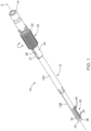
- the insertion instrument 10 includes a tube 12 having a proximal end 14 adapted to be gripped by a user and a distal end 16 adapted for insertion.
- the insertion instrument 10 is preferably for use in connection with ENT procedures, such as insertion of a balloon for expanding a sinus cavity. However, it can be used for various other medical or non-medical applications.
- the tube 12 is formed of a guide tube 12A located at the proximal end that is connected to an end tube 12B, located at the distal end.
- the end tube 12B includes a flexible portion 30.
- a tip control actuator 20 is located at the proximal end 14.
- This tip control actuator 20 comprises a rotatable grip 22.
- other types of tip control actuators 20 could be utilized, such as an axially slideable grip.
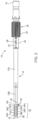
- the rotatable grip 22 has an internal thread 23.
- the rotatable grip 22 is axially fixed but rotatable on the tube 12.
- a sleeve 24 with an external thread 25 is provided, with the sleeve 24 being slideable on the tube 12 in an axial direction and the external thread 25 of the sleeve 24 is engaged with the internal thread 23 of the rotatable grip 22.
- the sleeve 24 further includes an axially extending slot 26, and a projection 27 that is connected to the tube 12 extends into the slot 26 in order to prevent rotation of the sleeve 24 during turning of the rotatable grip 22.
- At least one tension wire 60 is connected to the sleeve 24.
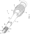
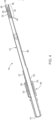
- the flexible portion 30 at the distal end 16 of the tube 12 includes a spine 32 as well as a plurality of circumferentially extending ribs 34A-34I that extend from the spine 32 which are axially spaced apart from a distal tip 38 of the end tube 12B toward the proximal end.
- the ribs are generally referred to as 34, and the specific number of ribs 34A-34I could be varied depending upon the particular application for the insertion instrument 10 as well as the amount of bend required from the flexible portion 30.
- the ribs 34 are spaced apart by wedge-shaped partial circumferential openings 40. A widest part 42 of these wedge-shaped openings 40 is located circumferentially opposite to the spine 32.
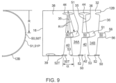
- the ribs 34 have first and second axial sides 35, 36, best shown in the enlarged detail of Figure 9 . These axial sides 35, 36 are defined by the wedge-shaped openings 40, with the first axial side 35 of one of the ribs, for example rib 34B, facing the second axial side 36 of an adjacent one of the ribs, for example rib 34A.
- rounded openings 44 are provided at the corners of the wedge-shaped openings 40 adjacent to the spine 32. These rounded openings 44 are preferably oval, having a major axis extending in a direction of the axis X of the insertion instrument 10.
- At least one of the first or second axial sides 35, 36 includes one of an axially extending projection 50 or a recess 52, and a facing one of the at least one of the first or second axial sides 35, 36 of an adjacent one of the ribs 34 includes at least one of a complementary mating recess 51 or a corresponding axial projection 53.
- the first rib 34A includes three of the axially extending projections 50 on the second axial side 36 and the facing first axial side 35 of an adjacent rib 34B includes three of the complementary mating recesses 51. Additionally, as can be seen most clearly in Figure 8 , the second axial side 36 of the first rib 34A includes a recess 52 and the first axial side 35 of the second rib 34B includes corresponding axial projections 53. While the illustrated embodiment includes both projections 50, 53 and recesses 51, 52 on both axial sides of the ribs 34, this is not required.
- the axially extending projections 50 and the corresponding complementary mating recesses 51 and/or the recesses 52 and the corresponding axial projections 53 in the plurality ribs 34A-34I are arranged in at least one axially extending row 55A, 55B, 55C, indicated in Figures 6 and 7 . More preferably, there are at least two rows 55A-55C of the axially extending projections 50 and the corresponding complementary mating recesses 51 and/or the recesses 52 and the corresponding axial projections 53.
- three of the axially extending rows 55A-55C of axially extending projections 50 and corresponding complementary mating recesses 51 and/or the recesses 52 and the corresponding axial projections 53 are provided.
- a first one of the rows 55A is located approximately 80°-100° from the spine 32.
- a second one of the rows 55B is located approximately 170°-190° from the spine 32.
- a third one of the rows 55C is preferably located approximately 260°-280° from the spine 32.
- This curved path is shown in detail in Figure 9 and preferably describes a radius R which generally corresponds to a bend radius of the tube end 12B at the location of the recesses 51 in the illustrated embodiment when it is being flexed.
- the projections, and in the illustrated embodiment only the axial projections 50, of the first and third rows 55A, 55C also have this complementary curved shape to the curved path of the corresponding complementary mating recesses 51.
- the axial projections 50 have a clearance in the circumferential direction of 0.1-0.4 mm with the complementary mating recesses 51.
- the corresponding axial projections 53 have the same clearance with the recesses 52.
- the axial projections 50 In the area of the preferably curved path of the axial projections 50 and mating recesses 51, preferably the axial projections 50 have a reduced insertion area indicated at 56 where a width of the axial projection is made smaller to allow for easier guidance and insertion of the axial projection 50 as it enters the mating recess 51. In this area, the clearance can be greater than 0.4 mm. This also facilitated manufacturing.
- the recesses 52 and/or the corresponding complementary mating recesses 51 of the second row 55B extend along a straight axial path, and the respective projections 50 or the corresponding axial projections 53 have a complementary shape.
- the end tube 12B is formed of superelastic material, such as Nitinol.
- the end tube 12B has a wall thickness of about 0.4-0.6 mm, and a diameter of 3.2-3.6 mm. Those skilled in the art will recognize that these dimensions can be changed for other applications and that other suitable materials may be utilized.
- At least one opening 39 is provided in the distal tip 38 to connect a tension wire 60.
- at least one tension wire 60 extends from the tip control actuator 20 to the distal tip 38 where it is anchored in the at least one opening 39.
- two of the tension wires are provided in order to maintain a reduced cross-sectional diameter of the tension wires that projects into the clear open cross-section of the tube 12B while still carrying the necessary loads from the tip control actuator 20 to the distal tip 38 required for elastically bending the flexible portion 30 at the distal end 16 of the tube 12.
- a complementary projection 50T or a mating recess 52T is located in the distal tip 38 facing the first axil side 35 of an adjacent one of the ribs 34A.
- a complementary projection 53P or recess 51P is provided in a part of the tube 12B facing the second axial side 36 of a proximal-most one of the ribs 34I. This is preferably provided in order to provide continuity in the ability to transfer normal forces against the flexible portion 30 of the distal end 16 of the tube 12 when it is in the flexed or bent position as discussed in further detail below.
- axial projections 50 are at least partially located in the corresponding complementary mating recesses 51 and/or the corresponding axial projections 53 are at least partially located in the recesses 52 in an unbent state of the distal end 16 of the tube 12. This partial overlap ensures a smooth bending of the flexible portion 30 of the tube 12 when the tip control actuator 20 is actuated by a user.
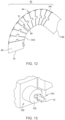
- the distal tip 38 upon application of a tension force on the tension wire 60 using the tip control actuator 20, the distal tip 38 is deflectable from an unbent state in which the distal tip remains aligned with the axis X of the insertion tool 10, to one or more intermediate states as shown in Figures 10 and 11 , in which the distal tip 38 is aligned at an angle to the axis X and at least some space remains between at least some of the first and second axial sides 35, 36 of the ribs 34, to a fully deflected state, as shown in Figure 12 , in which the first and second axial sides 35, 36 of the ribs 34 contact one another.
- the axial projections 50 are circumferentially braced against sides of corresponding complementary mating recesses 51 and/or the corresponding axial projections 53 are circumferentially braced against sides of the recesses 52 to maintain a rigidity of the distal tip 38 relative to a normally applied force on the distal tip 38.
- This is important for certain ENT applications where a normal force must be applied when the distal tip 38 is in the deflected position in order to push tissue out of the way as the insertion instrument 10 is advanced into a body cavity such as a sinus cavity.
- the wedge-shaped openings 40 may all have the same shape, as illustrated in detail in Figures 6 and 9 .
- at least some of the wedge-shaped openings 40 may have different shapes to provide a variable bend profile. This can be done by varying the angle a indicated in Figure 9 on some of the ribs at different locations.
- some of the ribs 34 may have different widths which can also be used to adjust the bend profile.
- the operator rotates the rotatable grip 22 in order to apply tension via the at least one tension wire 60 to the distal tip 38 such that the flexible portion 30 elastically bends into one or more of the intermediate or fully deflected states such as illustrated in Figures 10-12 in order to allow the operator to advance the insertion instrument 10 into the desired sinus cavity.
- an instrument can be inserted through the tube 12, into the sinus cavity. This has particular application in connection with the insertion of a balloon catheter into a sinus cavity.
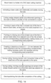
- a method for producing a bendable tip for an instrument 10 includes mounting a tube 12 for the instrument in a CNC controlled rotational and axially moveable holder 102 of a laser cutting machine 100. This step is generally indicated at 110 in Figure 14 .
- a laser cutting machine is the Quantum-Cut Tube machine available from Blueacre Technology Ltd. of Louth, Ireland which provides a high accuracy four axis cutter that allows for cutting and profiling of tubes.
- the moveable holder 102 includes a hollow chuck and long lengths of tube stock may be provided by inserting the tube stock through the chuck such that only a small portion of the tube is exposed for laser cutting.
- the laser 104 shown in Figure 13 , is then activated, as indicated in Figure 14 at 112.
- the CNC controlled moveable holder then rotationally and axially moves the tube under the laser cutter in order to cut the wedge-shaped partial circumferential openings 40 (as shown in Figure 9 ) in the tube 12 to define the plurality of ribs 34 which extend axially from the distal end of the tube 12.
- the ribs 34 are connected together by the axially extended spine 32. This is indicated at 114 in Figure 14 .
- at least one of an axial projection 50 or a recess 52 is formed in each of the ribs in at least one of the first or second axial sides 35, 36. This is indicated at 116 in Figure 14 .
- At least one of a corresponding complementary mating recess 51 or a corresponding axial projection 53 is formed in a facing one of the at least one of the first or second axial sides 35, 36 of an adjacent one of the ribs 34. This is indicated at 118 in Figure 14 .
- the complementary projections 53T or mating recesses 51T are formed in an axial side of the distal tip 38 that faces the first axial side 35 of a first one of the ribs 34A, and at least one of the complementary projections 53T or mating recesses 51T is aligned with a corresponding one of the recesses 52 or the axial projection 50 of the first one of the ribs 34A adjacent to the distal tip 38.
- At least one complementary projection 53P or a mating recess 51P is formed in an axial side of a part of the tube 12 facing the second axial side 36 of a last one of the ribs 34I that is adjacent to the proximal part of the tube 12.
- the complementary projection 53P or the mating recess 51P is aligned with the at least one of the recess 52 or the axially projection 50 on the second axial side 36 of the last one of the ribs 34I.
- a clearance in the circumferential direction of about 0.1-0.4 mm is provided in order to provide for smooth bending operation of the flexible portion 30 while still allowing the bracing contact between the respective projections and the recesses so that a normal force can be applied to the distal end 38 in use without the flexible portion 30 at the distal end 16 of the tube 12 collapsing or flexing.
- This is indicated at 120 in Figure 14 .
- a tension wire connection opening 39 is formed at the distal end 16 of the tube circumferentially opposite to the spine 32. This allows connection of the tension wire 60 to the distal tip 38 in a later step. This is indicated at 122 in Figure 14 .
- rounded openings 44 are formed at the corners of the wedge-shaped partial circumferential openings 40 adjacent to the spine 32. This is indicated at 124 in Figure 14 .
- the tube stock is advanced through the moveable holder 102 until a sufficient length is exposed to form the desired length for the tube 12 and the completed tube 12 is cut from the end of the tube stock. At that point the next cutting operating for forming the next tube 12 can be initiated.
- Electropolishing is preferred due to the smooth surface finish provided which does not include any abrasive scratch lines due to the electropolishing process used.
- an abrasive cleaning for example, in a shaker with an abrasive media could also be utilized.
- the tube 12 is complete, or if the only portion formed using laser cutting is the end tube 12B, this can be assembled with the guide tube 12A to complete the tube 12, and then the tip control actuator 20 can be assembled to the tube 12.
- the at least one tension wire 60 is then connected from the at least one connection opening 39 and extended through the tube 12 for connection to the tip control actuator 20.
- the insertion instrument 10 then provides the advantage of not requiring separate tips having different bend angles since the construction of the flexible portion 30 is specifically designed to allow for the application of a normal force without the distal tip 38 being unduly deflected in a manner that would hinder the insertion process, particularly in ENT applications.
Landscapes
- Health & Medical Sciences (AREA)
- Life Sciences & Earth Sciences (AREA)
- Engineering & Computer Science (AREA)
- General Health & Medical Sciences (AREA)
- Veterinary Medicine (AREA)
- Biomedical Technology (AREA)
- Heart & Thoracic Surgery (AREA)
- Animal Behavior & Ethology (AREA)
- Public Health (AREA)
- Surgery (AREA)
- Optics & Photonics (AREA)
- Physics & Mathematics (AREA)
- Hematology (AREA)
- Anesthesiology (AREA)
- Medical Informatics (AREA)
- Nuclear Medicine, Radiotherapy & Molecular Imaging (AREA)
- Molecular Biology (AREA)
- Biophysics (AREA)
- Pulmonology (AREA)
- Pathology (AREA)
- Plasma & Fusion (AREA)
- Mechanical Engineering (AREA)
- Vascular Medicine (AREA)
- Robotics (AREA)
- Gastroenterology & Hepatology (AREA)
- Oral & Maxillofacial Surgery (AREA)
- Media Introduction/Drainage Providing Device (AREA)
Claims (16)
- Verfahren zum Herstellen einer biegbaren Spitze für ein Instrument, umfassend:Anbringen einer Röhre (12) für ein Instrument in einem CNC-gesteuerten rotierenden und axial bewegbaren Halter (102) einer Laserschneidmaschine (100), wobei sich ein distales Ende (16) der Röhre aus dem Halter erstreckt;Aktivieren eines Laserschneiders (104);Laserschneiden von keilförmigen Teilumfangsöffnungen (40) in der Röhre, um eine Vielzahl sich radial erstreckender Rippen (34) an dem distalen Ende der Röhre zu definieren, wobei die Rippen durch einen sich axial erstreckenden Grat (32) miteinander verbunden sind, der sich in Umfangsrichtung gegenüber einem breitesten Teil der keilförmigen Öffnungen befindet, und die Rippen eine erste und eine zweite axiale Seite (35, 36) aufweisen;während des Laserschneidens, Ausbilden in jeder der Rippen an mindestens einer der ersten oder der zweiten axialen Seite von drei axialen Vorsprüngen (50) oder Vertiefungen (52), und Ausbilden an einer zugewandten der mindestens einen der ersten oder der zweiten axialen Seite einer angrenzenden der Rippen von drei entsprechenden komplementären passenden Vertiefungen (51) oder entsprechenden axialen Vorsprüngen (53),wobei die sich axial erstreckenden Vorsprünge und die entsprechenden komplementären passenden Vertiefungen und/oder die Vertiefungen und die entsprechenden axialen Vorsprünge in der Vielzahl von Rippen in sich axial erstreckenden Reihen ausgebildet sind;dadurch gekennzeichnet, dass die sich axial erstreckenden Reihen aus einer ersten der Reihen (55A), die etwa 80 - 100 Grad von dem Grat gelegen ist, einer zweiten der Reihen (55B), die etwa 170 - 190 Grad von dem Grat gelegen ist, und einer dritten der Reihen (55C) besteht, die etwa 260 - 280 Grad von dem Grat gelegen ist, wobei die Vertiefungen und/oder die entsprechenden komplementären passenden Vertiefungen der ersten und der dritten Reihe einen gekrümmten Pfad aufweisen, der sich von mindestens einer der ersten und der zweiten axialen Seite in Richtung des Grats erstreckt, und die Vorsprünge und/oder die entsprechenden axialen Vorsprünge der ersten und der dritten Reihe eine komplementäre gekrümmte Form zu dem gekrümmten Pfad der jeweiligen Vertiefungen oder der entsprechenden komplementären passenden Vertiefungen aufweisen.
- Verfahren nach Anspruch 1, ferner umfassend:
während des Laserschneidens, Ausbilden von mindestens einem von einem komplementären Vorsprung oder einer passenden Vertiefung in einer axialen Seite des Abschnitts der distalen Spitze, die der ersten axialen Seite einer ersten der Rippen zugewandt ist, die an den Abschnitt der distalen Spitze angrenzt, wobei das mindestens eine des axialen Vorsprungs oder der komplementären passenden Vertiefung an einem entsprechenden der Vertiefung oder des axialen Vorsprungs einer ersten der Rippen ausgerichtet ist, die an den Abschnitt der distalen Spitze angrenzt. - Verfahren nach Anspruch 1, ferner umfassend:
während des Laserschneidens, Ausbilden von mindestens einem von einem komplementären Vorsprung oder einer passenden Vertiefung in einer axialen Seite eines Teils der Röhre, die der zweiten axialen Seite einer letzten der Rippen zugewandt ist, die an einen proximalen Teil der Endröhre angrenzt, wobei der komplementäre Vorsprung oder die passende Vertiefung an mindestens einem der Vertiefung oder des axialen Vorsprungs auf der zweiten axialen Seite der letzten der Rippen ausgerichtet ist. - Verfahren nach Anspruch 1, ferner umfassend:während des Laserschneidens, Ausbilden von mindestens einer Spanndrahtverbindungsöffnung (39) an dem distalen Ende der Röhre in Umfangsrichtung gegenüber des Grats;Verbinden von mindestens einem Spanndraht (60) mit der distalen Spitze; undAusfahren des mindestens einen Spanndrahts durch die Röhre zu einem Spitzensteueraktuator (20), der an einem proximalen Ende der Röhre gelegen ist.
- Verfahren nach Anspruch 1, ferner umfassend:
Schaffen eines Abstands in einer Umfangsrichtung von etwa 0,1 - 0,4 mm zwischen den axialen Vorsprüngen und den komplementären passenden Vertiefungen und/oder den Vertiefungen und den entsprechenden axialen Vorsprüngen. - Verfahren nach Anspruch 1, ferner umfassend:
Ausbilden der Röhre aus einer Formgedächtnislegierung. - Verfahren nach Anspruch 6, wobei die Formgedächtnislegierung Nitinol ist.
- Verfahren nach Anspruch 1, ferner umfassend:
nach dem Laserschneiden, mindestens eines von einem Elektropolieren oder einem abrasiven Reinigen der Röhre. - Verfahren nach Anspruch 1, ferner umfassend:
während des Laserschneidens, Ausbilden einer Spanndrahtverbindungsöffnung (39) an dem distalen Ende der Röhre in Umfangsrichtung gegenüber des Grats. - Verfahren nach Anspruch 1, ferner umfassend:
während des Laserschneidens, Ausbilden von abgerundeten Öffnungen (44) an Ecken der keilförmigen Teilumfangsöffnungen angrenzend an den Grat. - Verfahren nach Anspruch 10, wobei die abgerundeten Öffnungen oval sind und eine Hauptachse aufweisen, die sich in der axialen Richtung der Röhre erstreckt.
- Verfahren nach Anspruch 1, ferner umfassend, während des Laserschneidens, das Ausbilden des mindestens einen des axialen Vorsprungs oder der Vertiefung in jeder der Rippen in mindestens einer der ersten oder der zweiten axialen Seite, die das mindestens eine der entsprechenden komplementären passenden Vertiefung oder des entsprechenden axialen Vorsprungs in der zugewandten der mindestens einen der ersten oder der zweiten axialen Seite der angrenzenden der Rippen überschneidet.
- Verfahren nach Anspruch 1, wobei die Röhre ein Teil einer Röhrenmateriallänge ist, und das Verfahren ferner umfassend:Anbringen des Röhrenmaterials in dem CNC-gesteuerten rotierenden und axial bewegbaren Halter, und nach dem Laserschneiden, Vorschieben des Röhrenmaterials durch den bewegbaren Halter, bis eine ausreichende Länge freigelegt ist, um eine gewünschte Länge für die Röhre auszubilden, undSchneiden der Röhre aus einem Ende des Röhrenmaterials.
- Verfahren nach Anspruch 1, wobei das Laserschneiden ferner das Laserschneiden der keilförmigen Teilumfangsöffnungen mit unterschiedlichen Formen umfasst, um ein variables Biegeprofil bereitzustellen.
- Verfahren nach Anspruch 1, wobei die Röhre eine Endröhre (12B) ist, und das Verfahren ferner umfassend ein Montieren der Endröhre mit einer Führungsröhre (12A).
- Verfahren nach Anspruch 1, ferner umfassend das Montieren eines Spitzensteueraktuators (20) an der Röhre.
Applications Claiming Priority (2)
| Application Number | Priority Date | Filing Date | Title |
|---|---|---|---|
| US201762490202P | 2017-04-26 | 2017-04-26 | |
| US15/867,091 US10933214B2 (en) | 2017-04-26 | 2018-01-10 | Method for producing a deflectable insertion tool |
Publications (3)
| Publication Number | Publication Date |
|---|---|
| EP3395259A1 EP3395259A1 (de) | 2018-10-31 |
| EP3395259B1 true EP3395259B1 (de) | 2025-03-05 |
| EP3395259C0 EP3395259C0 (de) | 2025-03-05 |
Family
ID=62152324
Family Applications (1)
| Application Number | Title | Priority Date | Filing Date |
|---|---|---|---|
| EP18169302.9A Active EP3395259B1 (de) | 2017-04-26 | 2018-04-25 | Verfahren zur herstellung eines ablenkbaren einsetzwerkzeugs |
Country Status (7)
| Country | Link |
|---|---|
| US (1) | US10933214B2 (de) |
| EP (1) | EP3395259B1 (de) |
| JP (1) | JP7106337B2 (de) |
| CN (1) | CN108836501B (de) |
| AU (1) | AU2018202683A1 (de) |
| CA (1) | CA3002438A1 (de) |
| IL (1) | IL258653B (de) |
Families Citing this family (7)
| Publication number | Priority date | Publication date | Assignee | Title |
|---|---|---|---|---|
| WO2020067421A1 (ja) | 2018-09-28 | 2020-04-02 | 東ソ-株式会社 | フッ素樹脂、フッ素樹脂粒子およびそれらの製造方法 |
| CN109567991B (zh) * | 2018-12-05 | 2021-02-19 | 东莞市先健医疗有限公司 | 输送鞘管 |
| US11213309B2 (en) * | 2019-05-23 | 2022-01-04 | Biosense Webster (Israel) Ltd. | Medical probe having improved maneuverability |
| WO2021105708A1 (en) * | 2019-11-27 | 2021-06-03 | Galvani Bioelectronics Limited | System and methods for laparoscopic delivery and deployment of a neural interface |
| CN114929129A (zh) * | 2020-01-16 | 2022-08-19 | 史密夫和内修有限公司 | 手术装置的铰接轴 |
| CN111166994A (zh) * | 2020-02-05 | 2020-05-19 | 上海汇禾医疗科技有限公司 | 套管组件及包含该套管组件的器械运输系统 |
| US20230371971A1 (en) * | 2022-05-18 | 2023-11-23 | Lenkbar, Llc | Surgical instrument shaft assembly with concentric segmented flexible tubes |
Citations (2)
| Publication number | Priority date | Publication date | Assignee | Title |
|---|---|---|---|---|
| US20170056171A1 (en) * | 2015-08-28 | 2017-03-02 | Edwards Lifesciences Cardiaq Llc | Steerable delivery system for replacement mitral valve and methods of use |
| EP4218672A1 (de) * | 2016-12-16 | 2023-08-02 | Edwards Lifesciences Corporation | Einsetzsysteme und werkzeuge zur einführung einer verankerungsvorrichtung für eine klappenprothese |
Family Cites Families (26)
| Publication number | Priority date | Publication date | Assignee | Title |
|---|---|---|---|---|
| DE19534112A1 (de) * | 1995-09-14 | 1997-03-20 | Wolf Gmbh Richard | Endoskopisches Instrument |
| WO2002060352A1 (en) * | 2001-01-30 | 2002-08-08 | Ev3 Santa Rosa, Inc. | Medical system and method for remodeling an extravascular tissue structure |
| US7842028B2 (en) * | 2005-04-14 | 2010-11-30 | Cambridge Endoscopic Devices, Inc. | Surgical instrument guide device |
| US20060063973A1 (en) | 2004-04-21 | 2006-03-23 | Acclarent, Inc. | Methods and apparatus for treating disorders of the ear, nose and throat |
| US7720521B2 (en) | 2004-04-21 | 2010-05-18 | Acclarent, Inc. | Methods and devices for performing procedures within the ear, nose, throat and paranasal sinuses |
| US10188413B1 (en) | 2004-04-21 | 2019-01-29 | Acclarent, Inc. | Deflectable guide catheters and related methods |
| JP2008541797A (ja) | 2005-05-03 | 2008-11-27 | ハンセン メディカル,インク. | ロボットガイドカテーテルシステム |
| AU2009257472A1 (en) | 2008-06-10 | 2009-12-17 | Sonoma Orthopedic Products, Inc. | Fracture fixation device, tools and methods |
| US9326843B2 (en) | 2009-01-16 | 2016-05-03 | Claret Medical, Inc. | Intravascular blood filters and methods of use |
| US8461478B2 (en) * | 2009-02-03 | 2013-06-11 | Abbott Cardiovascular Systems, Inc. | Multiple beam laser system for forming stents |
| DE202009012793U1 (de) * | 2009-05-29 | 2010-01-28 | Aesculap Ag | Chirurgisches Instrument |
| DE202009012796U1 (de) * | 2009-05-29 | 2009-11-26 | Aesculap Ag | Chirurgisches Instrument |
| US20110112365A1 (en) * | 2009-06-03 | 2011-05-12 | Gyrus Acmi, Inc. | Endoscope shaft |
| US9795765B2 (en) * | 2010-04-09 | 2017-10-24 | St. Jude Medical International Holding S.À R.L. | Variable stiffness steering mechanism for catheters |
| CA2812507A1 (en) | 2010-09-24 | 2012-03-29 | Entrigue Surgical, Inc. | Systems, devices and methods for providing therapy to an anatomical structure using high frequency pressure waves and/or cryogenic temperatures |
| WO2012071464A1 (en) | 2010-11-22 | 2012-05-31 | Dfine, Inc. | System for use in treatment of vertebral fractures |
| CN103764216B (zh) | 2011-05-03 | 2016-08-17 | 施菲姆德控股有限责任公司 | 可转向输送护套 |
| US9282993B1 (en) * | 2013-03-15 | 2016-03-15 | Southern Methodist University | Steerable extendable devices |
| US9827126B2 (en) | 2013-08-27 | 2017-11-28 | Covidien Lp | Delivery of medical devices |
| KR102313708B1 (ko) | 2013-10-25 | 2021-10-19 | 인튜어티브 서지컬 오퍼레이션즈 인코포레이티드 | 매립된 작동 도관을 갖는 가요성 기구 |
| US9839765B2 (en) | 2013-11-12 | 2017-12-12 | St. Jude Medical, Cardiology Division, Inc. | Transfemoral mitral valve repair delivery device |
| JP5816779B1 (ja) | 2014-02-18 | 2015-11-18 | オリンパス株式会社 | 内視鏡用湾曲管及び内視鏡 |
| EP3750502A1 (de) | 2014-09-04 | 2020-12-16 | Memic Innovative Surgery Ltd. | Vorrichtung und system mit mechanischen armen |
| US20160262754A1 (en) * | 2015-03-12 | 2016-09-15 | Nir Altman | Flexible tack guide |
| US10420537B2 (en) * | 2015-03-27 | 2019-09-24 | Shifamed Holdings, Llc | Steerable medical devices, systems, and methods of use |
| US20160346513A1 (en) | 2015-05-26 | 2016-12-01 | Vanderbilt University | Surgical device tip with arc length varying curvature |
-
2018
- 2018-01-10 US US15/867,091 patent/US10933214B2/en active Active
- 2018-04-11 IL IL258653A patent/IL258653B/en active IP Right Grant
- 2018-04-18 AU AU2018202683A patent/AU2018202683A1/en not_active Abandoned
- 2018-04-24 CA CA3002438A patent/CA3002438A1/en not_active Abandoned
- 2018-04-25 EP EP18169302.9A patent/EP3395259B1/de active Active
- 2018-04-25 JP JP2018083637A patent/JP7106337B2/ja active Active
- 2018-04-26 CN CN201810385965.5A patent/CN108836501B/zh active Active
Patent Citations (2)
| Publication number | Priority date | Publication date | Assignee | Title |
|---|---|---|---|---|
| US20170056171A1 (en) * | 2015-08-28 | 2017-03-02 | Edwards Lifesciences Cardiaq Llc | Steerable delivery system for replacement mitral valve and methods of use |
| EP4218672A1 (de) * | 2016-12-16 | 2023-08-02 | Edwards Lifesciences Corporation | Einsetzsysteme und werkzeuge zur einführung einer verankerungsvorrichtung für eine klappenprothese |
Also Published As
| Publication number | Publication date |
|---|---|
| JP7106337B2 (ja) | 2022-07-26 |
| CN108836501B (zh) | 2023-08-04 |
| JP2018183594A (ja) | 2018-11-22 |
| CA3002438A1 (en) | 2018-10-26 |
| IL258653A (en) | 2018-06-28 |
| US20180311465A1 (en) | 2018-11-01 |
| US10933214B2 (en) | 2021-03-02 |
| CN108836501A (zh) | 2018-11-20 |
| EP3395259A1 (de) | 2018-10-31 |
| EP3395259C0 (de) | 2025-03-05 |
| IL258653B (en) | 2021-06-30 |
| AU2018202683A1 (en) | 2018-11-15 |
Similar Documents
| Publication | Publication Date | Title |
|---|---|---|
| EP3395259B1 (de) | Verfahren zur herstellung eines ablenkbaren einsetzwerkzeugs | |
| EP3395271B1 (de) | Auslenkbares einführungswerkzeug | |
| EP3958944B1 (de) | Lenkbarer führungsdraht mit verbessertem drehmoment | |
| KR102000243B1 (ko) | 관절식 안과 수술용 프로브 | |
| JP5111612B2 (ja) | 小口径腹腔鏡手術装置 | |
| ES2908813T3 (es) | Instrumento orientable que comprende espaciadores radiales entre elementos cilíndricos coaxiales | |
| KR20210145189A (ko) | 슬롯형 구조체를 갖는 힌지를 포함하는 조종가능한 기구 | |
| JP2008513124A (ja) | レーザーエネルギーの方向性送達のための装置および方法 | |
| KR20170129056A (ko) | 편향가능한 팁을 가진 삽입 튜브 | |
| CN112546402B (zh) | 能够弯曲的导丝 | |
| KR20240033268A (ko) | 내시경 또는 침습적 적용을 위한 조향 가능한 기구 | |
| JP2025529576A (ja) | 制御可能な特徴を有する医療用ガイドワイヤデバイス | |
| KR20240122823A (ko) | 내시경 또는 침습적 적용을 위한 조향 가능한 기구 | |
| EP4448071A2 (de) | Lenkbares instrument für endoskopische oder invasive anwendungen | |
| WO2014013564A1 (ja) | 医療用処置具 | |
| WO2025026670A1 (en) | Bendable tube with path length compensation of steering wires |
Legal Events
| Date | Code | Title | Description |
|---|---|---|---|
| PUAI | Public reference made under article 153(3) epc to a published international application that has entered the european phase |
Free format text: ORIGINAL CODE: 0009012 |
|
| STAA | Information on the status of an ep patent application or granted ep patent |
Free format text: STATUS: THE APPLICATION HAS BEEN PUBLISHED |
|
| AK | Designated contracting states |
Kind code of ref document: A1 Designated state(s): AL AT BE BG CH CY CZ DE DK EE ES FI FR GB GR HR HU IE IS IT LI LT LU LV MC MK MT NL NO PL PT RO RS SE SI SK SM TR |
|
| AX | Request for extension of the european patent |
Extension state: BA ME |
|
| STAA | Information on the status of an ep patent application or granted ep patent |
Free format text: STATUS: REQUEST FOR EXAMINATION WAS MADE |
|
| 17P | Request for examination filed |
Effective date: 20190430 |
|
| RBV | Designated contracting states (corrected) |
Designated state(s): AL AT BE BG CH CY CZ DE DK EE ES FI FR GB GR HR HU IE IS IT LI LT LU LV MC MK MT NL NO PL PT RO RS SE SI SK SM TR |
|
| STAA | Information on the status of an ep patent application or granted ep patent |
Free format text: STATUS: EXAMINATION IS IN PROGRESS |
|
| 17Q | First examination report despatched |
Effective date: 20211216 |
|
| GRAP | Despatch of communication of intention to grant a patent |
Free format text: ORIGINAL CODE: EPIDOSNIGR1 |
|
| STAA | Information on the status of an ep patent application or granted ep patent |
Free format text: STATUS: GRANT OF PATENT IS INTENDED |
|
| RIC1 | Information provided on ipc code assigned before grant |
Ipc: A61B 18/00 20060101ALN20240920BHEP Ipc: A61M 25/01 20060101ALI20240920BHEP Ipc: A61B 17/24 20060101ALI20240920BHEP Ipc: A61B 17/34 20060101ALI20240920BHEP Ipc: A61B 17/00 20060101AFI20240920BHEP |
|
| INTG | Intention to grant announced |
Effective date: 20241008 |
|
| GRAS | Grant fee paid |
Free format text: ORIGINAL CODE: EPIDOSNIGR3 |
|
| GRAA | (expected) grant |
Free format text: ORIGINAL CODE: 0009210 |
|
| STAA | Information on the status of an ep patent application or granted ep patent |
Free format text: STATUS: THE PATENT HAS BEEN GRANTED |
|
| AK | Designated contracting states |
Kind code of ref document: B1 Designated state(s): AL AT BE BG CH CY CZ DE DK EE ES FI FR GB GR HR HU IE IS IT LI LT LU LV MC MK MT NL NO PL PT RO RS SE SI SK SM TR |
|
| REG | Reference to a national code |
Ref country code: GB Ref legal event code: FG4D |
|
| REG | Reference to a national code |
Ref country code: CH Ref legal event code: EP |
|
| REG | Reference to a national code |
Ref country code: DE Ref legal event code: R096 Ref document number: 602018079761 Country of ref document: DE |
|
| REG | Reference to a national code |
Ref country code: IE Ref legal event code: FG4D |
|
| U01 | Request for unitary effect filed |
Effective date: 20250402 |
|
| U07 | Unitary effect registered |
Designated state(s): AT BE BG DE DK EE FI FR IT LT LU LV MT NL PT RO SE SI Effective date: 20250408 |
|
| U20 | Renewal fee for the european patent with unitary effect paid |
Year of fee payment: 8 Effective date: 20250407 |
|
| PG25 | Lapsed in a contracting state [announced via postgrant information from national office to epo] |
Ref country code: RS Free format text: LAPSE BECAUSE OF FAILURE TO SUBMIT A TRANSLATION OF THE DESCRIPTION OR TO PAY THE FEE WITHIN THE PRESCRIBED TIME-LIMIT Effective date: 20250605 |
|
| PG25 | Lapsed in a contracting state [announced via postgrant information from national office to epo] |
Ref country code: ES Free format text: LAPSE BECAUSE OF FAILURE TO SUBMIT A TRANSLATION OF THE DESCRIPTION OR TO PAY THE FEE WITHIN THE PRESCRIBED TIME-LIMIT Effective date: 20250305 |
|
| PGFP | Annual fee paid to national office [announced via postgrant information from national office to epo] |
Ref country code: GB Payment date: 20250410 Year of fee payment: 8 |
|
| PG25 | Lapsed in a contracting state [announced via postgrant information from national office to epo] |
Ref country code: NO Free format text: LAPSE BECAUSE OF FAILURE TO SUBMIT A TRANSLATION OF THE DESCRIPTION OR TO PAY THE FEE WITHIN THE PRESCRIBED TIME-LIMIT Effective date: 20250605 |
|
| PG25 | Lapsed in a contracting state [announced via postgrant information from national office to epo] |
Ref country code: HR Free format text: LAPSE BECAUSE OF FAILURE TO SUBMIT A TRANSLATION OF THE DESCRIPTION OR TO PAY THE FEE WITHIN THE PRESCRIBED TIME-LIMIT Effective date: 20250305 |
|
| PG25 | Lapsed in a contracting state [announced via postgrant information from national office to epo] |
Ref country code: GR Free format text: LAPSE BECAUSE OF FAILURE TO SUBMIT A TRANSLATION OF THE DESCRIPTION OR TO PAY THE FEE WITHIN THE PRESCRIBED TIME-LIMIT Effective date: 20250606 |
|
| PG25 | Lapsed in a contracting state [announced via postgrant information from national office to epo] |
Ref country code: SM Free format text: LAPSE BECAUSE OF FAILURE TO SUBMIT A TRANSLATION OF THE DESCRIPTION OR TO PAY THE FEE WITHIN THE PRESCRIBED TIME-LIMIT Effective date: 20250305 |
|
| PG25 | Lapsed in a contracting state [announced via postgrant information from national office to epo] |
Ref country code: PL Free format text: LAPSE BECAUSE OF FAILURE TO SUBMIT A TRANSLATION OF THE DESCRIPTION OR TO PAY THE FEE WITHIN THE PRESCRIBED TIME-LIMIT Effective date: 20250305 |
|
| PG25 | Lapsed in a contracting state [announced via postgrant information from national office to epo] |
Ref country code: CZ Free format text: LAPSE BECAUSE OF FAILURE TO SUBMIT A TRANSLATION OF THE DESCRIPTION OR TO PAY THE FEE WITHIN THE PRESCRIBED TIME-LIMIT Effective date: 20250305 |
|
| PG25 | Lapsed in a contracting state [announced via postgrant information from national office to epo] |
Ref country code: SK Free format text: LAPSE BECAUSE OF FAILURE TO SUBMIT A TRANSLATION OF THE DESCRIPTION OR TO PAY THE FEE WITHIN THE PRESCRIBED TIME-LIMIT Effective date: 20250305 |
|
| PG25 | Lapsed in a contracting state [announced via postgrant information from national office to epo] |
Ref country code: IS Free format text: LAPSE BECAUSE OF FAILURE TO SUBMIT A TRANSLATION OF THE DESCRIPTION OR TO PAY THE FEE WITHIN THE PRESCRIBED TIME-LIMIT Effective date: 20250705 |
|
| REG | Reference to a national code |
Ref country code: CH Ref legal event code: H13 Free format text: ST27 STATUS EVENT CODE: U-0-0-H10-H13 (AS PROVIDED BY THE NATIONAL OFFICE) Effective date: 20251125 |