EP3395189A1 - Continuous fermentation device - Google Patents
Continuous fermentation device Download PDFInfo
- Publication number
- EP3395189A1 EP3395189A1 EP16879137.4A EP16879137A EP3395189A1 EP 3395189 A1 EP3395189 A1 EP 3395189A1 EP 16879137 A EP16879137 A EP 16879137A EP 3395189 A1 EP3395189 A1 EP 3395189A1
- Authority
- EP
- European Patent Office
- Prior art keywords
- fermented
- objects
- conveyor belt
- fermentation
- fermentation device
- Prior art date
- Legal status (The legal status is an assumption and is not a legal conclusion. Google has not performed a legal analysis and makes no representation as to the accuracy of the status listed.)
- Granted
Links
Images





Classifications
-
- C—CHEMISTRY; METALLURGY
- C12—BIOCHEMISTRY; BEER; SPIRITS; WINE; VINEGAR; MICROBIOLOGY; ENZYMOLOGY; MUTATION OR GENETIC ENGINEERING
- C12M—APPARATUS FOR ENZYMOLOGY OR MICROBIOLOGY; APPARATUS FOR CULTURING MICROORGANISMS FOR PRODUCING BIOMASS, FOR GROWING CELLS OR FOR OBTAINING FERMENTATION OR METABOLIC PRODUCTS, i.e. BIOREACTORS OR FERMENTERS
- C12M23/00—Constructional details, e.g. recesses, hinges
- C12M23/44—Multiple separable units; Modules
-
- A—HUMAN NECESSITIES
- A23—FOODS OR FOODSTUFFS; TREATMENT THEREOF, NOT COVERED BY OTHER CLASSES
- A23N—MACHINES OR APPARATUS FOR TREATING HARVESTED FRUIT, VEGETABLES OR FLOWER BULBS IN BULK, NOT OTHERWISE PROVIDED FOR; PEELING VEGETABLES OR FRUIT IN BULK; APPARATUS FOR PREPARING ANIMAL FEEDING- STUFFS
- A23N17/00—Apparatus specially adapted for preparing animal feeding-stuffs
-
- B—PERFORMING OPERATIONS; TRANSPORTING
- B01—PHYSICAL OR CHEMICAL PROCESSES OR APPARATUS IN GENERAL
- B01F—MIXING, e.g. DISSOLVING, EMULSIFYING OR DISPERSING
- B01F33/00—Other mixers; Mixing plants; Combinations of mixers
-
- B—PERFORMING OPERATIONS; TRANSPORTING
- B01—PHYSICAL OR CHEMICAL PROCESSES OR APPARATUS IN GENERAL
- B01F—MIXING, e.g. DISSOLVING, EMULSIFYING OR DISPERSING
- B01F33/00—Other mixers; Mixing plants; Combinations of mixers
- B01F33/26—Mixers with an endless belt for transport of the material, e.g. in layers or with mixing means above or at the end of the belt
-
- B—PERFORMING OPERATIONS; TRANSPORTING
- B01—PHYSICAL OR CHEMICAL PROCESSES OR APPARATUS IN GENERAL
- B01F—MIXING, e.g. DISSOLVING, EMULSIFYING OR DISPERSING
- B01F33/00—Other mixers; Mixing plants; Combinations of mixers
- B01F33/80—Mixing plants; Combinations of mixers
- B01F33/81—Combinations of similar mixers, e.g. with rotary stirring devices in two or more receptacles
- B01F33/811—Combinations of similar mixers, e.g. with rotary stirring devices in two or more receptacles in two or more consecutive, i.e. successive, mixing receptacles or being consecutively arranged
-
- B—PERFORMING OPERATIONS; TRANSPORTING
- B01—PHYSICAL OR CHEMICAL PROCESSES OR APPARATUS IN GENERAL
- B01F—MIXING, e.g. DISSOLVING, EMULSIFYING OR DISPERSING
- B01F35/00—Accessories for mixers; Auxiliary operations or auxiliary devices; Parts or details of general application
-
- B—PERFORMING OPERATIONS; TRANSPORTING
- B65—CONVEYING; PACKING; STORING; HANDLING THIN OR FILAMENTARY MATERIAL
- B65G—TRANSPORT OR STORAGE DEVICES, e.g. CONVEYORS FOR LOADING OR TIPPING, SHOP CONVEYOR SYSTEMS OR PNEUMATIC TUBE CONVEYORS
- B65G15/00—Conveyors having endless load-conveying surfaces, i.e. belts and like continuous members, to which tractive effort is transmitted by means other than endless driving elements of similar configuration
-
- B—PERFORMING OPERATIONS; TRANSPORTING
- B65—CONVEYING; PACKING; STORING; HANDLING THIN OR FILAMENTARY MATERIAL
- B65G—TRANSPORT OR STORAGE DEVICES, e.g. CONVEYORS FOR LOADING OR TIPPING, SHOP CONVEYOR SYSTEMS OR PNEUMATIC TUBE CONVEYORS
- B65G15/00—Conveyors having endless load-conveying surfaces, i.e. belts and like continuous members, to which tractive effort is transmitted by means other than endless driving elements of similar configuration
- B65G15/22—Conveyors having endless load-conveying surfaces, i.e. belts and like continuous members, to which tractive effort is transmitted by means other than endless driving elements of similar configuration comprising a series of co-operating units
-
- B—PERFORMING OPERATIONS; TRANSPORTING
- B65—CONVEYING; PACKING; STORING; HANDLING THIN OR FILAMENTARY MATERIAL
- B65G—TRANSPORT OR STORAGE DEVICES, e.g. CONVEYORS FOR LOADING OR TIPPING, SHOP CONVEYOR SYSTEMS OR PNEUMATIC TUBE CONVEYORS
- B65G21/00—Supporting or protective framework or housings for endless load-carriers or traction elements of belt or chain conveyors
- B65G21/20—Means incorporated in, or attached to, framework or housings for guiding load-carriers, traction elements or loads supported on moving surfaces
-
- C—CHEMISTRY; METALLURGY
- C12—BIOCHEMISTRY; BEER; SPIRITS; WINE; VINEGAR; MICROBIOLOGY; ENZYMOLOGY; MUTATION OR GENETIC ENGINEERING
- C12M—APPARATUS FOR ENZYMOLOGY OR MICROBIOLOGY; APPARATUS FOR CULTURING MICROORGANISMS FOR PRODUCING BIOMASS, FOR GROWING CELLS OR FOR OBTAINING FERMENTATION OR METABOLIC PRODUCTS, i.e. BIOREACTORS OR FERMENTERS
- C12M27/00—Means for mixing, agitating or circulating fluids in the vessel
- C12M27/16—Vibrating; Shaking; Tilting
-
- C—CHEMISTRY; METALLURGY
- C12—BIOCHEMISTRY; BEER; SPIRITS; WINE; VINEGAR; MICROBIOLOGY; ENZYMOLOGY; MUTATION OR GENETIC ENGINEERING
- C12M—APPARATUS FOR ENZYMOLOGY OR MICROBIOLOGY; APPARATUS FOR CULTURING MICROORGANISMS FOR PRODUCING BIOMASS, FOR GROWING CELLS OR FOR OBTAINING FERMENTATION OR METABOLIC PRODUCTS, i.e. BIOREACTORS OR FERMENTERS
- C12M29/00—Means for introduction, extraction or recirculation of materials, e.g. pumps
- C12M29/06—Nozzles; Sprayers; Spargers; Diffusers
-
- C—CHEMISTRY; METALLURGY
- C12—BIOCHEMISTRY; BEER; SPIRITS; WINE; VINEGAR; MICROBIOLOGY; ENZYMOLOGY; MUTATION OR GENETIC ENGINEERING
- C12M—APPARATUS FOR ENZYMOLOGY OR MICROBIOLOGY; APPARATUS FOR CULTURING MICROORGANISMS FOR PRODUCING BIOMASS, FOR GROWING CELLS OR FOR OBTAINING FERMENTATION OR METABOLIC PRODUCTS, i.e. BIOREACTORS OR FERMENTERS
- C12M33/00—Means for introduction, transport, positioning, extraction, harvesting, peeling or sampling of biological material in or from the apparatus
-
- F—MECHANICAL ENGINEERING; LIGHTING; HEATING; WEAPONS; BLASTING
- F24—HEATING; RANGES; VENTILATING
- F24F—AIR-CONDITIONING; AIR-HUMIDIFICATION; VENTILATION; USE OF AIR CURRENTS FOR SCREENING
- F24F7/00—Ventilation
- F24F7/007—Ventilation with forced flow
-
- B—PERFORMING OPERATIONS; TRANSPORTING
- B01—PHYSICAL OR CHEMICAL PROCESSES OR APPARATUS IN GENERAL
- B01F—MIXING, e.g. DISSOLVING, EMULSIFYING OR DISPERSING
- B01F23/00—Mixing according to the phases to be mixed, e.g. dispersing or emulsifying
- B01F23/20—Mixing gases with liquids
- B01F23/23—Mixing gases with liquids by introducing gases into liquid media, e.g. for producing aerated liquids
- B01F23/231—Mixing gases with liquids by introducing gases into liquid media, e.g. for producing aerated liquids by bubbling
- B01F23/23105—Arrangement or manipulation of the gas bubbling devices
- B01F23/2312—Diffusers
- B01F23/23123—Diffusers consisting of rigid porous or perforated material
- B01F23/231231—Diffusers consisting of rigid porous or perforated material the outlets being in the form of perforations
-
- B—PERFORMING OPERATIONS; TRANSPORTING
- B01—PHYSICAL OR CHEMICAL PROCESSES OR APPARATUS IN GENERAL
- B01F—MIXING, e.g. DISSOLVING, EMULSIFYING OR DISPERSING
- B01F23/00—Mixing according to the phases to be mixed, e.g. dispersing or emulsifying
- B01F23/20—Mixing gases with liquids
- B01F23/23—Mixing gases with liquids by introducing gases into liquid media, e.g. for producing aerated liquids
- B01F23/231—Mixing gases with liquids by introducing gases into liquid media, e.g. for producing aerated liquids by bubbling
- B01F23/23105—Arrangement or manipulation of the gas bubbling devices
- B01F23/2312—Diffusers
- B01F23/23126—Diffusers characterised by the shape of the diffuser element
- B01F23/231265—Diffusers characterised by the shape of the diffuser element being tubes, tubular elements, cylindrical elements or set of tubes
Definitions
- the present disclosure relates to a fermentation device, and more specifically, to a continuous fermentation device which can perform fermentation of continuously fed objects to be fermented while transporting the objects.
- soybean meal As a source of vegetable proteins for livestock, raw grain materials or by-products which remain after the extraction of active ingredients from the raw grain materials are mainly utilized as raw materials for feed.
- Typical examples of such vegetable proteins are soybean meal, corn gluten, etc.
- Soybean meal is a dehulled and defatted component of soybean meal and is currently used as various kinds of feeds of livestock, such as pigs, chickens, beef cattle, etc.
- soybean meal has problems in that it has a lower protein content compared to animal proteins, insufficient contents of some vitamins, minerals, and unknown growth factors (UGF), and also contains various kinds of anti-nutritional factors (ANFs), thus decreasing digestibility when used as feed.
- anti-nutritional factors such as trypsin inhibitor can decrease digestibility in young livestock and thereby inhibit their growth, the amount of soybean meal to be added to feed has been limited.
- soybean meal with improved quality is currently used for various livestock feeds both home and abroad.
- a representative example is soybean meal.
- a representative method for preparing fermented soybean meal is as follows.
- a beneficial microorganism is introduced into soybean meal and the soybean meal is stored in a batch fermenter for a certain period of time.
- the soybean meal fermented by the beneficial microorganism is dried and crushed, and used as a main source of vegetable proteins to be added in the compound feed.
- the main production facilities for preparing the fermented soybean meal may be largely classified into a high-temperature steam facility capable of lowering the population of general microorganisms contaminating soybean meal, a solid fermentation facility for performing solid fermentation by mixing soybean meal with a beneficial microorganism, and a drying facility for drying the fermented soybean meal after fermentation, and a crushing facility for crushing the fermented soybean meal to a size to be used as feed.
- the most important part requiring technological advance in the process of preparing the fermented soybean meal is the part of the solid fermentation facility. Based on the presumption that beneficial microorganisms will have the same effect and the same fermentation time, it is speculated that the effect and efficiency of the solid fermentation equipment in the manufacturing facility of the fermented soybean meal can realize a high quality product and reduction of manufacturing costs.
- the solid fermenter for fermented soybean meal may vary depending on the kind of the beneficial microorganism.
- temperature and air permeability may be considered as major factors.
- temperature is mostly controlled within the batch fermenter.
- the batch fermenter as disclosed in Patent Document 1 below is mainly used due to its excellent fermentability and simple operation technique.
- the requirement of the number of fermenters and the size of the fermenters are a source of major investment costs.
- the conventional batch fermentation device performs fermentation as follows.
- Raw materials (objects to be fermented) fed into the input unit 1 are distributed and fed into a plurality of fermentation modules (A) by undergoing steaming and cooling processes in steaming unit 2 and cooling unit 3, and the seed microorganism cultured in the cultivation unit 4 is introduced into a plurality of fermentation modules (A) to ferment the objects to be fermented.
- a plurality of odor-processing units (6a, 6b, 6c, and 6d) for treating odors generated during the fermentation process must be provided in each fermentation device (A), and the completed objects to be fermented are sucked through the suction unit 5 connected to each fermentation device (A) through a pipe and transferred to a drying unit.
- the conventional batch fermentation device has disadvantages in that, due to the characteristics of the batch fermentation, cleaning time for removing contaminants in the fermentation device, time for feeding the strain and the raw materials, and time for discharging the fermentation product are required; the pipes may be clogged during the suction of the fermented objects to be fermented; and additionally, the productivity of the final product per fermenter is very low because each of these processes is intermittently performed in each fermentation device (A).
- Patent Document 1 KR 2015-0008265 A
- an object of the present disclosure is to provide a continuous fermentation device which enables continuous fermentation of objects to be fermented so that feeding of a raw material, performing fermentation, and discharging of a fermentation product, etc. in one facility, thereby preventing problems that may occur during the operation owing to the simplified process and facility and reducing the costs for constituting the facility by reducing manufacturing facilities.
- the present disclosure provides a continuous fermentation device including a plurality of fermentation modules, each fermentation module including:
- the plurality of fermentation modules are preferably in a stacked form where one side and the opposite side of each conveyor belt are connected to each other, and the continuously fed objects to be fermented are continuously fermented while being passed through the plurality of fermentation modules.
- the plurality of conveyor belts of the plurality of fermentation modules preferably form a stack of two rows, and each of the plurality of fermentation modules further includes a belt connection part, which connects one side and the opposite side of each of the conveyor belts in each row, and the continuously fed objects to be fermented are continuously fermented while being passed through the fermentation modules.
- Each of the agitators preferably includes:
- Each of the agitators preferably agitates the objects to be fermented, which are transported on the conveyor belt as each of the agitating frames moves, as the shaft rotates.
- the continuous fermentation device preferably includes agitation wings, in which each agitation wing is located on one side of the outer circumference of the plurality of agitating frames in the longitudinal direction.
- the shaft is preferably height-adjustable.
- the air diffuser preferably includes:
- the apertures are preferably formed in at least two rows and the objects to be fermented are supplied with air through the apertures.
- Each of the distribution pipes preferably injects air inside the objects to be fermented when the objects to be fermented are transported on the conveyor belt.
- Each row formed by the apertures is preferably arranged at a predetermined angle from the center of the distribution pipes.
- the apertures are preferably arranged in three rows on one side of the outer circumference of the distribution pipes 320, in which each row formed by the apertures is arranged with an angular difference of from 60 degrees or greater to 90 degrees or less from the center of the distribution pipes.
- the continuous fermentation device preferably further includes guides, which have a predetermined height and are located in the longitudinal direction on both sides of the conveyor belt.
- the continuous fermentation device preferably further includes a conveyor belt which transports the objects to be fermented that are continuously fermented and discharged to a drying unit.
- the continuous fermentation device preferably further includes:
- the continuous fermentation device enables continuous performance of feeding of a raw material, performing fermentation, discharging of a fermentation product, etc. in one facility, and as a result, the processing time can be significantly reduced, thereby reducing the operation time of the production process. Accordingly, the continuous fermentation device of the present disclosure can improve business competitiveness by reducing investment costs, improving productivity, etc. in the development of mass production through solid fermentation, thereby having the effect of significantly reducing the manufacturing costs of products manufactured therefrom.
- Each component of the continuous fermentation device of the present disclosure may be used as an integral unit or as an independent unit, as needed.
- some components of the continuous fermentation device may be omitted depending on the forms of usage.
- the continuous fermentation device of the present disclosure may include fermentation modules 100, where each fermentation modules 100 is provided with a conveyor belt 110, agitators 200, air diffusers 300, and guides 120; and as further shown in FIGS. 1 and 3 , the continuous fermentation device of the present disclosure may be configured in a form where a plurality of fermentation modules 100 are stacked, whereby the installation space can be efficiently utilized.
- the conveyor belt 110 is located in a predetermined longitudinal direction so that objects to be fermented arriving at one side 111 of the conveyor belt 110 are transported to be discharged through the opposite side 112.
- the agitators 200 are located on the conveyor belt 110 and agitate the objects to be fermented which are transported by the conveyor belt 110.
- the agitators 200 may include a shaft 210, support frames 220, connecting frames 230, agitating frames 240, and cylinders 260.
- the shaft 210 is located being spaced a predetermined distance upward across the transport direction of the conveyor belt 110.
- Each of the plurality of support frames 220 radially extends from one side and the other side of the shaft 210, and each connecting frame 230 connects each end of the support frames 220.
- Each agitating frame 240 is located across each connecting frame 230 to act upon rotation of the shaft 210, and the objects to be fermented that are transported on the conveyor belt 110 are agitated by the agitating frames 240.
- the agitating frames 240 may be provided with an agitation wing 250 located along the longitudinal direction thereof, and as such, the area of contact with the objects to be fermented can be increased, thereby enabling a more effective agitation.
- the cylinders 260 connected to both sides of the shaft 210 allow the up-and-down movement of the shaft, and thereby, the agitation height can be adjusted according to the height of the objects to be fermented that are transported.
- the agitators 200 When the temperature of the objects to be fermented rises above the appropriate fermentation temperature by the heat generated during the fermentation, the agitators 200 agitate the objects to be fermented and thereby lower the temperature of the objects so that an appropriate temperature can be maintained.
- Each air diffuser 300 is located on one side of the conveyor belt 110 and supplies air to the objects to be fermented.
- each air diffuser 300 may include a main supply pipe 310 and distribution pipes 320.
- the main supply pipe 310 being extended on the conveyor belt 110, is located across the conveyor belt 110, and air is supplied thereto through an air supply unit 600 connected to one side thereof.
- the amount of air being supplied from the air supply unit 600 into the main supply pipe 310 can be controlled using an air-controlling means such as a valve 311, etc., disposed on the main supply pipe 310.
- Each distribution pipe 320 is connected to the main supply pipe 310 and extended toward the transport direction of conveyor belt 110 so as to have a certain length.
- the distribution pipe 320 may be provided in a plurality according to the width of the conveyor belt 110, and a plurality of apertures 331 are formed around the periphery thereof so that the air introduced through the main supply pipe 310 can be distributed through a plurality of distribution pipes 320 and supplied through the apertures 331 to the objects to be fermented being transported on the conveyor belt 110.
- each distribution pipe 320 becomes disposed inside of the stacked objects to be fermented, thereby enabling oxygen supply into the inside of the stacked objects to be fermented.
- the plurality of apertures 331 may be disposed to be formed in two or more rows. Furthermore, referring to FIGS. 7A and 7B , effective ventilation to the objects to be fermented can be achieved by pre-setting the intervals between the rows formed by the apertures 331 and the angle of the air being injected from the apertures 331 before air injection, according to the amount of the objects to be fermented.
- the intervals between the rows of the apertures 331 may be arranged to be formed at 90 degrees ( FIG. 7A ) or 60 degrees ( FIG. 7B ), respectively, from one side of the distribution pipe 320.
- the air supply may encounter resistance in a solid state, and thus, the number of the apertures 331 and the intervals between the apertures are important for uniform air delivery to the objects to be fermented. That is, when the apertures 331 are formed in only one row and the pressure for the air to be supplied is significantly increased, the air may be delivered to the entirety of the objects to be fermented. However, in this case, the objects to be fermented located near the apertures will be over-supplied with air, which causes drying rather than fermentation, thus making it difficult to achieve uniform fermentation over the entirety of the objects to be fermented. Accordingly, uniform fermentation can be achieved by supplying air to the entirety of the objects to be fermented by disposing the apertures 331 in two or more rows so that the intervals therebetween are arranged at a predetermined angle from the center.
- each distribution pipe 320 at one end portion thereof is provided with a cap capable of opening and closing of the distribution pipe 320, and thus, the inside of each distribution pipe 320 can be cleaned by easily opening and closing the cap.
- Guides 120 are located in the longitudinal direction on both sides of the conveyor belt 110, and referring further to FIG. 8 , the guides 120 have a predetermined height on both sides of the conveyor belt 110, and supporting units 121 that support the guides 120 may be located at one side of each of the guides 120.
- the objects to be fermented transported on the conveyor belt 110 are transported while being passed through between the guides 120.
- a phenomenon occurs in which the objects to be fermented are spread on both sides.
- the falling-off of these objects to be fermented from both sides of the conveyor belt 110 may be prevented by allowing extra space on both sides.
- the width of the conveyor belt 110 will become greater, thus lowering utilization of the space.
- the spreading phenomenon of the objects to be fermented on the conveyor belt 110 and the resulting falling-off of the objects can be prevented and the width of the conveyor belt can also be minimized.
- each conveyor belt 110 a plurality of air conditioning devices 500 for removing odors generated during fermentation of the objects to be fermented are installed.
- Each of the air conditioning devices 500 is connected to a single odor-processing unit 60, and thus there is an advantage in that the odors collected by suction in each air conditioning device 500 can be treated in the single odor-processing unit 60.
- a plurality of fermentation modules 100 are stacked in a row and one side 111 and the opposite side 112 of each fermentation module 100, specifically, one side 111 and the other side 112 of each conveyor belt 110 are disposed in an alternating manner. That is, the fermentation is performed in such a manner that the objects to be fermented fed into one side 111 of the conveyor belt 110 are transported into the opposite side 112 and discharged, and the discharged objects to be fermented are again transported from one side 111 of the conveyor belt 110 located on a lower part thereof to the opposite side 112 thereof (see arrows in FIGS. 1 and 2 ).
- a hopper that guides the objects to be fermented, which are discharged from a conveyor belt 110 and fed into the conveyor belt 110 on a lower location thereof, and a pulverizing unit 400 which pulverizes the objects to be fermented may be located between each of the fermentation modules 100.
- the air diffusers 300 are connected to each other and disposed as such, and air can be supplied from the air supply unit 600 located furthest to the bottom to the inter-connected air diffusers 300.
- a plurality of fermentation modules 100 are stacked as described above, focusing on the difference compared to the above embodiment as follows, again referring to FIGS. 3 and 4 .
- a plurality of fermentation modules 100 are stacked in two rows, and sides 111 and the opposite sides 112 of fermentation modules 100 located on different rows from each other are disposed to be connected by a belt connection part 150.
- the shape of the belt connection part 150 is not limited, but it may be in a curved shape for smooth transport of the objects to be fermented.
- the fed objects to be fermented are sequentially transported from a conveyor belt 110 in one row to a conveyor belt 110 in another row through the belt connection part 150 in an approximately elliptical shape, and thereby the objects to be fermented are fermented (see arrows in FIGS. 3 and 4 ).
- the conveyor belt 110' is located connecting the opposite side of the fermentation module 100 in the final position to a drying unit, and the fermentation products, which are continuously discharged upon completion of fermentation, are transported to the drying unit (not shown).
- the continuous fermentation device of the present disclosure can effectively transport and dry a fermentation product being continuously discharged, and enables smooth transport and drying of the fermentation product without clogging of pipes, etc., unlike the conventional batch fermentation device utilizing a suction method.
- the continuous fermentation device according to the present disclosure is described as an experimental example to explain the difference from the conventional batch fermentation device.
- solid fermentation was performed by applying the continuous fermentation device according to the present disclosure. As shown in FIG.
- the raw material (i.e., the objects to be fermented) introduced through the feeding unit 10 was fed into a fermentation device (B) consisting of a plurality of fermentation modules 100 after undergoing steaming and cooling processes in steaming unit 20 and cooling unit 30, the seed microorganism cultured in a cultivation unit 40 was added thereto and the objects to be fermented were continuously fermented, and the fermentation product being discharged upon completion of fermentation was transported to a drying unit through the conveyor belt 110' and dried.
- a fermentation device (B) consisting of a plurality of fermentation modules 100 after undergoing steaming and cooling processes in steaming unit 20 and cooling unit 30, the seed microorganism cultured in a cultivation unit 40 was added thereto and the objects to be fermented were continuously fermented, and the fermentation product being discharged upon completion of fermentation was transported to a drying unit through the conveyor belt 110' and dried.
- soybean meal was used as the raw material (i.e., the objects to be fermented) and the amount of soybean meal used was 60 kg to 90 kg based on the raw material.
- water was added (water content: at a 43% level), and then, steaming was performed to sterilize the soybean meal to which the water was added.
- the average temperature of the soybean meal was maintained at 70°C to 90°C for 20 minutes.
- the soybean meal underwent a cooling process and the seed microorganism was inoculated so as to perform the solid fermentation.
- Plantarum K2G a subspecies of Bacillus amyloliquefaciens
- the seed microorganism was inoculated at a concentration of 10% relative to the weight of the raw material so as to secure the total number of the microorganism of 1 ⁇ 10 7 cfu/mL or greater at the initial stage.
- the cultivation of the seed microorganism was activated in GYP medium (glucose 10.0 g, yeast extract 8.0 g, and polypeptone 2.0 g (pH 7.0)).
- the objects to be fermented were fed to a height of 20 cm as a standard and samples were collected at 4-hour intervals for confirming the growth process of the seed microorganism and the change in quality of the fermentation product.
- the changes in the viable cell count (cfu/g), water content (%) of the fermentation product, and crude protein content (%) of each sample were measured.
- the fermentation of a seed microorganism is completed within 24 hours and the quality (viable cell count: 1 ⁇ 10 9 cfu/g or greater, final water content: 32% or less, and increase of crude protein: 6% or greater).
- the control of the temperature of the fermentation product and air permeability for oxygen supply were optimized through the agitators 200 and air diffusers 300.
- the distribution pipes 320 of the air diffusers 300 were inserted into the objects to be fermented, whereby the air permeability can be improved and the change in the overall quality of the fermentation product can be minimized.
- the temperature of the objects to be fermented was controlled as follows while observing the change in temperature of the objects to be fermented.
- the temperature of the fermentation product was increased to a certain temperature (45°C) or higher, the agitators 200 were operated, and the temperature of the objects to be fermented was induced to decrease through the contact of the objects to be fermented with air by these agitators 200, and thereby the temperature change of the objects to be fermented from 47°C to 39°C was confirmed.
- the temperature change by the agitators 200 alone was confirmed and the effect of air diffusion during the agitation was confirmed.
- the distribution pipes 320 of the air diffusers 300 were arranged in a transport direction on a conveyor belt 110 to be suitable for the continuous fermentation device using the conveyor belt 110, and the apertures 331 were provided in the distribution pipes 320 so that the apertures 331 are optimized for each size (2 mm to 3 mm) and for each location. Additionally, for optimum oxygen supply as described above, the distribution pipes 320 were arranged in 3 to 8 rows, and the angles of the apertures 331 were adjusted according to the arrangement so that air could be evenly and forcibly ventilated into the objects to be fermented (see FIG. 6 ).
- the fermentability and quality of fermentation products were evaluated using the secured air diffusers 300. As shown in FIG. 10 , the growth/proliferation of the microorganism was shown to be almost identical to that in the batch fermentation device. As shown in FIG. 11 , it was confirmed that the change in water content during solid fermentation was also shown to be at the same rate as in the batch fermentation device. These results show that the heat generated inside the objects to be fermented through aerobic fermentation is appropriately discharged to the outside.
- the main purpose of the application of the seed microorganism, Bacillus is to induce the peptidation of proteins in soybean meal through enzymatic hydrolysis (the protease in Bacillus ), and this effect improves feed digestibility, thereby improving feed nutrition efficiency.
- the activity and KOH solubility of trypsin inhibitor (i.e., a representative inhibitor of digestibility) were measured. As shown in Table 2 below, it was confirmed that the activity of trypsin inhibitor, an anti-nutritional factor, was decreased during the processes of treating raw materials, steaming, and fermentation. Additionally, the KOH solubility was also confirmed to be excellent compared to that prepared by the batch fermentation device, and the comparison of final quality revealed that the quality of the product prepared by the continuous fermentation device of the present disclosure was equal to or higher than that prepared by the batch fermentation device. From these results, it can be concluded that the Bacillus fermentation efficiency is superior in the continuous fermentation device according to the present disclosure.
- oxygen delivery can be more effectively performed by arranging the air diffusers 300 so as to facilitate oxygen supply within the solid objects to be fermented and this will enable the maintenance of optimal fermentation conditions. Additionally, the device of the present disclosure can maximize the solid fermentation of aerobic microorganisms and ensure the quality of the fermentation product.
- the results of the quality of the fermentation product prepared by the device of the present disclosure were secured by enhancing the major control factors with regard to solid objects to be fermented, such as temperature of a fermentation product or air feeding into the objects to be fermented (air permeability), and this is a factor that can provide many opportunities for cost reduction by improving productivity through continuous operation and efficient installation space in the progress of industrialization.
- the device for agitation can be installed at a lower cost, and the device can be configured to allow ventilation in various places for all of the objects to be fermented, thus being effective for aerobic fermentation.
- the device of the present disclosure has an advantage in that it is sufficiently possible to further reduce the investment cost of the facility according to the height of the objects to be fermented.
- the guide belt 120 provided on the conveyor belt 110 can prevent falling-off of the objects to be fermented and subsequent contamination thereof.
- surface resistance of the guides 120 may occur during fermentation if fermentation is performed after the guides 120 are provided.
- the guides 120 did not show any surface resistance during this experiment, and it was confirmed that all of the objects to be fermented were sufficient for aerobic fermentation by the air delivered by the distribution pipes 320 described above.
Landscapes
- Engineering & Computer Science (AREA)
- Chemical & Material Sciences (AREA)
- Life Sciences & Earth Sciences (AREA)
- Health & Medical Sciences (AREA)
- Wood Science & Technology (AREA)
- Organic Chemistry (AREA)
- Bioinformatics & Cheminformatics (AREA)
- Zoology (AREA)
- Mechanical Engineering (AREA)
- General Engineering & Computer Science (AREA)
- Chemical Kinetics & Catalysis (AREA)
- Microbiology (AREA)
- Sustainable Development (AREA)
- Biotechnology (AREA)
- Biomedical Technology (AREA)
- Biochemistry (AREA)
- Genetics & Genomics (AREA)
- General Health & Medical Sciences (AREA)
- Combustion & Propulsion (AREA)
- Polymers & Plastics (AREA)
- Food Science & Technology (AREA)
- Clinical Laboratory Science (AREA)
- Molecular Biology (AREA)
- Processing Of Solid Wastes (AREA)
- Fertilizers (AREA)
- Apparatuses For Bulk Treatment Of Fruits And Vegetables And Apparatuses For Preparing Feeds (AREA)
- Apparatus Associated With Microorganisms And Enzymes (AREA)
- Animal Husbandry (AREA)
- Fodder In General (AREA)
Abstract
Description
- The present disclosure relates to a fermentation device, and more specifically, to a continuous fermentation device which can perform fermentation of continuously fed objects to be fermented while transporting the objects.
- As a source of vegetable proteins for livestock, raw grain materials or by-products which remain after the extraction of active ingredients from the raw grain materials are mainly utilized as raw materials for feed. Typical examples of such vegetable proteins are soybean meal, corn gluten, etc. Soybean meal is a dehulled and defatted component of soybean meal and is currently used as various kinds of feeds of livestock, such as pigs, chickens, beef cattle, etc. Currently, soybean meal has problems in that it has a lower protein content compared to animal proteins, insufficient contents of some vitamins, minerals, and unknown growth factors (UGF), and also contains various kinds of anti-nutritional factors (ANFs), thus decreasing digestibility when used as feed. In particular, since anti-nutritional factors such as trypsin inhibitor can decrease digestibility in young livestock and thereby inhibit their growth, the amount of soybean meal to be added to feed has been limited.
- To solve the above problems, studies have been performed for the purpose of decreasing the content of anti-nutritional factors while improving digestibility through fermentation using microorganisms, and soybean meal with improved quality is currently used for various livestock feeds both home and abroad. A representative example is soybean meal.
- A representative method for preparing fermented soybean meal is as follows. A beneficial microorganism is introduced into soybean meal and the soybean meal is stored in a batch fermenter for a certain period of time. The soybean meal fermented by the beneficial microorganism is dried and crushed, and used as a main source of vegetable proteins to be added in the compound feed.
- The main production facilities for preparing the fermented soybean meal may be largely classified into a high-temperature steam facility capable of lowering the population of general microorganisms contaminating soybean meal, a solid fermentation facility for performing solid fermentation by mixing soybean meal with a beneficial microorganism, and a drying facility for drying the fermented soybean meal after fermentation, and a crushing facility for crushing the fermented soybean meal to a size to be used as feed. The most important part requiring technological advance in the process of preparing the fermented soybean meal is the part of the solid fermentation facility. Based on the presumption that beneficial microorganisms will have the same effect and the same fermentation time, it is speculated that the effect and efficiency of the solid fermentation equipment in the manufacturing facility of the fermented soybean meal can realize a high quality product and reduction of manufacturing costs.
- Basically, the solid fermenter for fermented soybean meal may vary depending on the kind of the beneficial microorganism. In a case where an aerobic microorganism is used, temperature and air permeability may be considered as major factors. For effective control of temperature and ventilation, temperature is mostly controlled within the batch fermenter.
- The batch fermenter as disclosed in
Patent Document 1 below is mainly used due to its excellent fermentability and simple operation technique. However, in the case of mass production in the feed industry, the requirement of the number of fermenters and the size of the fermenters are a source of major investment costs. - As shown in
FIG. 18 , the conventional batch fermentation device performs fermentation as follows. Raw materials (objects to be fermented) fed into theinput unit 1 are distributed and fed into a plurality of fermentation modules (A) by undergoing steaming and cooling processes in steamingunit 2 andcooling unit 3, and the seed microorganism cultured in thecultivation unit 4 is introduced into a plurality of fermentation modules (A) to ferment the objects to be fermented. Additionally, a plurality of odor-processing units (6a, 6b, 6c, and 6d) for treating odors generated during the fermentation process must be provided in each fermentation device (A), and the completed objects to be fermented are sucked through thesuction unit 5 connected to each fermentation device (A) through a pipe and transferred to a drying unit. However, the conventional batch fermentation device has disadvantages in that, due to the characteristics of the batch fermentation, cleaning time for removing contaminants in the fermentation device, time for feeding the strain and the raw materials, and time for discharging the fermentation product are required; the pipes may be clogged during the suction of the fermented objects to be fermented; and additionally, the productivity of the final product per fermenter is very low because each of these processes is intermittently performed in each fermentation device (A). - Accordingly, there is a need for the development of a fermenter required for solid fermentation of soybean meal and other grains in a cost-effective manner. Additionally, there is a need for the development of a continuous fermentation device so as to improve the productivity of the batch fermenter.
- (Patent Document 1)
KR 2015-0008265 A - Under these circumstances, the present disclosure is contrived based on the conventional problems described above so as to solve the problems thereof. Accordingly, an object of the present disclosure is to provide a continuous fermentation device which enables continuous fermentation of objects to be fermented so that feeding of a raw material, performing fermentation, and discharging of a fermentation product, etc. in one facility, thereby preventing problems that may occur during the operation owing to the simplified process and facility and reducing the costs for constituting the facility by reducing manufacturing facilities.
- To achieve the above object, the present disclosure provides a continuous fermentation device including a plurality of fermentation modules, each fermentation module including:
- a conveyor belt, which transports objects to be fermented that are continuously fed thereinto from one side to the opposite side thereof;
- agitators, which are located on the conveyor belt; and
- air diffusers, which are located on one side of the conveyor belt,
- wherein the continuously fed objects to be fermented are fermented while being passed through the fermentation modules and are continuously discharged.
- The plurality of fermentation modules are preferably in a stacked form where one side and the opposite side of each conveyor belt are connected to each other, and the continuously fed objects to be fermented are continuously fermented while being passed through the plurality of fermentation modules.
- The plurality of conveyor belts of the plurality of fermentation modules preferably form a stack of two rows, and each of the plurality of fermentation modules further includes a belt connection part, which connects one side and the opposite side of each of the conveyor belts in each row, and the continuously fed objects to be fermented are continuously fermented while being passed through the fermentation modules.
- Each of the agitators preferably includes:
- a shaft, which is located on the conveyor belt;
- a plurality of support frames, wherein each support frame radially extends from one side and the opposite side of the outer circumference of the shaft;
- connecting frames, wherein each connecting frame connects the ends of the support frames located at each of the opposite sides of the shaft; and
- a plurality of agitating frames, wherein each agitating frame connects the connecting frames on one side and the opposite side.
- Each of the agitators preferably agitates the objects to be fermented, which are transported on the conveyor belt as each of the agitating frames moves, as the shaft rotates.
- The continuous fermentation device preferably includes agitation wings, in which each agitation wing is located on one side of the outer circumference of the plurality of agitating frames in the longitudinal direction.
- The shaft is preferably height-adjustable.
- The air diffuser preferably includes:
- a main supply pipe, which is located across the top side of the conveyor belt on one side of the conveyor belt; and
- distribution pipes, wherein each distribution pipe extends from one side of the main supply pipe and is located in the longitudinal direction of the top side of the conveyor belt, and a plurality of apertures are formed around the periphery thereof.
- The apertures are preferably formed in at least two rows and the objects to be fermented are supplied with air through the apertures.
- Each of the distribution pipes preferably injects air inside the objects to be fermented when the objects to be fermented are transported on the conveyor belt.
- Each row formed by the apertures is preferably arranged at a predetermined angle from the center of the distribution pipes.
- The apertures are preferably arranged in three rows on one side of the outer circumference of the
distribution pipes 320, in which each row formed by the apertures is arranged with an angular difference of from 60 degrees or greater to 90 degrees or less from the center of the distribution pipes. - The continuous fermentation device preferably further includes guides, which have a predetermined height and are located in the longitudinal direction on both sides of the conveyor belt.
- The continuous fermentation device preferably further includes a conveyor belt which transports the objects to be fermented that are continuously fermented and discharged to a drying unit.
- The continuous fermentation device preferably further includes:
- a plurality of air conditioning devices, which are provided on one side of each of the conveyor belt for suction of odors generated during the fermentation process of the objects to be fermented; and
- odor-processing units, which are connected to the plurality of air conditioning devices,
- in which the odors sucked from the plurality of air conditioning devices are integrated and processed in the odor-processing units.
- As described above, the continuous fermentation device according to the present disclosure enables continuous performance of feeding of a raw material, performing fermentation, discharging of a fermentation product, etc. in one facility, and as a result, the processing time can be significantly reduced, thereby reducing the operation time of the production process. Accordingly, the continuous fermentation device of the present disclosure can improve business competitiveness by reducing investment costs, improving productivity, etc. in the development of mass production through solid fermentation, thereby having the effect of significantly reducing the manufacturing costs of products manufactured therefrom.
-
-
FIG. 1 is an overall perspective view of a continuous fermentation device according to an embodiment of the present disclosure. -
FIG. 2 is a side view of a continuous fermentation device according to an embodiment of the present disclosure. -
FIG. 3 is an overall perspective view of a continuous fermentation device according to another embodiment of the present disclosure. -
FIG. 4 is a side view of a continuous fermentation device according to another embodiment of the present disclosure. -
FIG. 5 is a perspective view illustrating the configuration of an agitator in detail. -
FIG. 6 is a perspective view illustrating the configuration of an air diffuser in detail. -
FIGS. 7A and 7B are cross-sectional views taken along the line A-A' inFIG. 6 , illustrating the arrangement of the apertures and the air injection angles. -
FIG. 8 is a plan view of the conveyor belt portion viewed from above. -
FIG. 9 shows one side of a cross-section taken along the line B-B' inFIG. 8 . -
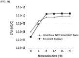
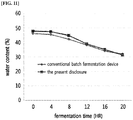
FIGS. 10 to 13 show the comparison results with respect to fermentation effects between the conventional batch fermentation device and a continuous fermentation device according to the present disclosure: a graph on the number of live microorganisms (FIG. 10 ), a graph on water content (FIG. 11 ), a graph on crude proteins (CP) (FIG. 12 ), and SDS-PAGE results (FIG. 13 ), respectively. -
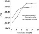
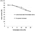
FIGS. 14 to 16 show the comparison results with respect to fermentation effects between the conventional batch fermentation device and a continuous fermentation device according to the present disclosure: a graph on the number of live microorganisms (FIG. 14 ), a graph on a graph on crude proteins (CP) (FIG. 15 ), and water content (FIG. 16 ), respectively. -
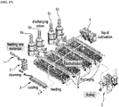
FIG. 17 shows an overall fermentation process of objects to be fermented using the continuous fermentation device according to the present disclosure. -
FIG. 18 shows a fermentation process of objects to be fermented according to a conventional batch fermentation device. - The above objects, features, and other advantages of the present disclosure will become more apparent by describing in detail preferred embodiments of the present disclosure with reference to the accompanying drawings. During this process, the thicknesses of the lines and the sizes of the components shown in the drawings may be exaggerated for clarity and convenience of explanation. Additionally, the following terms are defined in consideration of the functions in the present disclosure, which may vary depending on the intentions or customs of the user or operator. Therefore, the definitions of these terms must be described based on the contents throughout this specification.
- Furthermore, the embodiments described are provided for illustrative purposes of explanation and are not intended to limit the technical scope of the present disclosure.
- Each component of the continuous fermentation device of the present disclosure may be used as an integral unit or as an independent unit, as needed. In addition, some components of the continuous fermentation device may be omitted depending on the forms of usage.
- Hereinafter, a continuous fermentation device according to an embodiment of the present disclosure will be described in detail with reference to accompanying
FIGS. 1 to 17 . - As shown in
FIGS. 2 and4 , the continuous fermentation device of the present disclosure may includefermentation modules 100, where eachfermentation modules 100 is provided with aconveyor belt 110,agitators 200,air diffusers 300, and guides 120; and as further shown inFIGS. 1 and3 , the continuous fermentation device of the present disclosure may be configured in a form where a plurality offermentation modules 100 are stacked, whereby the installation space can be efficiently utilized. - The
conveyor belt 110 is located in a predetermined longitudinal direction so that objects to be fermented arriving at oneside 111 of theconveyor belt 110 are transported to be discharged through theopposite side 112. - The
agitators 200 are located on theconveyor belt 110 and agitate the objects to be fermented which are transported by theconveyor belt 110. - Describing the configuration of the
agitators 200 in more detail by referring toFIG. 5 , theagitators 200 may include ashaft 210, support frames 220, connectingframes 230, agitatingframes 240, andcylinders 260. - The
shaft 210 is located being spaced a predetermined distance upward across the transport direction of theconveyor belt 110. - Each of the plurality of support frames 220 radially extends from one side and the other side of the
shaft 210, and each connectingframe 230 connects each end of the support frames 220. - Each agitating
frame 240 is located across each connectingframe 230 to act upon rotation of theshaft 210, and the objects to be fermented that are transported on theconveyor belt 110 are agitated by the agitating frames 240. - The agitating frames 240 may be provided with an
agitation wing 250 located along the longitudinal direction thereof, and as such, the area of contact with the objects to be fermented can be increased, thereby enabling a more effective agitation. - Additionally, the
cylinders 260 connected to both sides of theshaft 210 allow the up-and-down movement of the shaft, and thereby, the agitation height can be adjusted according to the height of the objects to be fermented that are transported. - When the temperature of the objects to be fermented rises above the appropriate fermentation temperature by the heat generated during the fermentation, the
agitators 200 agitate the objects to be fermented and thereby lower the temperature of the objects so that an appropriate temperature can be maintained. - Each
air diffuser 300 is located on one side of theconveyor belt 110 and supplies air to the objects to be fermented. - Explaining the configuration of each
air diffuser 300 in more detail by referring toFIG. 6 , eachair diffuser 300 may include amain supply pipe 310 anddistribution pipes 320. - The
main supply pipe 310, being extended on theconveyor belt 110, is located across theconveyor belt 110, and air is supplied thereto through anair supply unit 600 connected to one side thereof. The amount of air being supplied from theair supply unit 600 into themain supply pipe 310 can be controlled using an air-controlling means such as avalve 311, etc., disposed on themain supply pipe 310. - Each
distribution pipe 320 is connected to themain supply pipe 310 and extended toward the transport direction ofconveyor belt 110 so as to have a certain length. Thedistribution pipe 320 may be provided in a plurality according to the width of theconveyor belt 110, and a plurality ofapertures 331 are formed around the periphery thereof so that the air introduced through themain supply pipe 310 can be distributed through a plurality ofdistribution pipes 320 and supplied through theapertures 331 to the objects to be fermented being transported on theconveyor belt 110. - Specifically, the objects to be fermented are stacked up to a certain height and transported on the conveyor, and as the objects to be fermented are transported, each
distribution pipe 320 becomes disposed inside of the stacked objects to be fermented, thereby enabling oxygen supply into the inside of the stacked objects to be fermented. - Additionally, the plurality of
apertures 331 may be disposed to be formed in two or more rows. Furthermore, referring toFIGS. 7A and 7B , effective ventilation to the objects to be fermented can be achieved by pre-setting the intervals between the rows formed by theapertures 331 and the angle of the air being injected from theapertures 331 before air injection, according to the amount of the objects to be fermented. In addition, as shown inFIG. 7 , when theapertures 331 of thedistribution pipe 320 are formed in three rows, the intervals between the rows of theapertures 331 may be arranged to be formed at 90 degrees (FIG. 7A ) or 60 degrees (FIG. 7B ), respectively, from one side of thedistribution pipe 320. This is because, in the fermentation of a solid material such as soybean, unlike in a liquid state, the air supply may encounter resistance in a solid state, and thus, the number of theapertures 331 and the intervals between the apertures are important for uniform air delivery to the objects to be fermented. That is, when theapertures 331 are formed in only one row and the pressure for the air to be supplied is significantly increased, the air may be delivered to the entirety of the objects to be fermented. However, in this case, the objects to be fermented located near the apertures will be over-supplied with air, which causes drying rather than fermentation, thus making it difficult to achieve uniform fermentation over the entirety of the objects to be fermented. Accordingly, uniform fermentation can be achieved by supplying air to the entirety of the objects to be fermented by disposing theapertures 331 in two or more rows so that the intervals therebetween are arranged at a predetermined angle from the center. - Additionally, each
distribution pipe 320 at one end portion thereof is provided with a cap capable of opening and closing of thedistribution pipe 320, and thus, the inside of eachdistribution pipe 320 can be cleaned by easily opening and closing the cap. -
Guides 120 are located in the longitudinal direction on both sides of theconveyor belt 110, and referring further toFIG. 8 , theguides 120 have a predetermined height on both sides of theconveyor belt 110, and supportingunits 121 that support theguides 120 may be located at one side of each of theguides 120. - That is, the objects to be fermented transported on the
conveyor belt 110 are transported while being passed through between theguides 120. When the objects to be fermented are transported on theconveyor belt 110, a phenomenon occurs in which the objects to be fermented are spread on both sides. The falling-off of these objects to be fermented from both sides of theconveyor belt 110 may be prevented by allowing extra space on both sides. However, in such case, the width of theconveyor belt 110 will become greater, thus lowering utilization of the space. Meanwhile, by providing theguide 120 on both sides of theconveyor belt 110, the spreading phenomenon of the objects to be fermented on theconveyor belt 110 and the resulting falling-off of the objects can be prevented and the width of the conveyor belt can also be minimized. - Additionally, on the top side of each
conveyor belt 110, a plurality ofair conditioning devices 500 for removing odors generated during fermentation of the objects to be fermented are installed. Each of theair conditioning devices 500 is connected to a single odor-processingunit 60, and thus there is an advantage in that the odors collected by suction in eachair conditioning device 500 can be treated in the single odor-processingunit 60. - In an embodiment, a case where a plurality of
fermentation modules 100 are stacked as described above is explained as follows, again referring toFIGS. 1 and2 . A plurality offermentation modules 100 are stacked in a row and oneside 111 and theopposite side 112 of eachfermentation module 100, specifically, oneside 111 and theother side 112 of eachconveyor belt 110 are disposed in an alternating manner. That is, the fermentation is performed in such a manner that the objects to be fermented fed into oneside 111 of theconveyor belt 110 are transported into theopposite side 112 and discharged, and the discharged objects to be fermented are again transported from oneside 111 of theconveyor belt 110 located on a lower part thereof to theopposite side 112 thereof (see arrows inFIGS. 1 and2 ). - Additionally, a hopper that guides the objects to be fermented, which are discharged from a
conveyor belt 110 and fed into theconveyor belt 110 on a lower location thereof, and apulverizing unit 400 which pulverizes the objects to be fermented may be located between each of thefermentation modules 100. Additionally, theair diffusers 300 are connected to each other and disposed as such, and air can be supplied from theair supply unit 600 located furthest to the bottom to theinter-connected air diffusers 300. - Additionally, in another embodiment, a case is explained where a plurality of
fermentation modules 100 are stacked as described above, focusing on the difference compared to the above embodiment as follows, again referring toFIGS. 3 and 4 . A plurality offermentation modules 100 are stacked in two rows, andsides 111 and theopposite sides 112 offermentation modules 100 located on different rows from each other are disposed to be connected by abelt connection part 150. The shape of thebelt connection part 150 is not limited, but it may be in a curved shape for smooth transport of the objects to be fermented. Accordingly, the fed objects to be fermented are sequentially transported from aconveyor belt 110 in one row to aconveyor belt 110 in another row through thebelt connection part 150 in an approximately elliptical shape, and thereby the objects to be fermented are fermented (see arrows inFIGS. 3 and 4 ). - Additionally, the conveyor belt 110'is located connecting the opposite side of the
fermentation module 100 in the final position to a drying unit, and the fermentation products, which are continuously discharged upon completion of fermentation, are transported to the drying unit (not shown). - Accordingly, the continuous fermentation device of the present disclosure can effectively transport and dry a fermentation product being continuously discharged, and enables smooth transport and drying of the fermentation product without clogging of pipes, etc., unlike the conventional batch fermentation device utilizing a suction method.
- Hereinafter, again referring to
FIGS. 1 to 17 , the continuous fermentation device according to the present disclosure is described as an experimental example to explain the difference from the conventional batch fermentation device. To confirm the differences in fermentability and quality with the existing batch fermentation device, solid fermentation was performed by applying the continuous fermentation device according to the present disclosure. As shown inFIG. 17 , the raw material (i.e., the objects to be fermented) introduced through thefeeding unit 10, was fed into a fermentation device (B) consisting of a plurality offermentation modules 100 after undergoing steaming and cooling processes in steamingunit 20 andcooling unit 30, the seed microorganism cultured in acultivation unit 40 was added thereto and the objects to be fermented were continuously fermented, and the fermentation product being discharged upon completion of fermentation was transported to a drying unit through the conveyor belt 110' and dried. - For this experiment, soybean meal was used as the raw material (i.e., the objects to be fermented) and the amount of soybean meal used was 60 kg to 90 kg based on the raw material. For the effective fermentation of the raw material (i.e., soybean meal), water was added (water content: at a 43% level), and then, steaming was performed to sterilize the soybean meal to which the water was added. During the steaming process, the average temperature of the soybean meal was maintained at 70°C to 90°C for 20 minutes. After the steaming process, the soybean meal underwent a cooling process and the seed microorganism was inoculated so as to perform the solid fermentation. As the seed microorganism, Plantarum K2G, a subspecies of Bacillus amyloliquefaciens, was used. For the stable growth of the seed microorganism, the seed microorganism was inoculated at a concentration of 10% relative to the weight of the raw material so as to secure the total number of the microorganism of 1×10⁷ cfu/mL or greater at the initial stage. The cultivation of the seed microorganism was activated in GYP medium (glucose 10.0 g, yeast extract 8.0 g, and polypeptone 2.0 g (pH 7.0)).
- The objects to be fermented were fed to a height of 20 cm as a standard and samples were collected at 4-hour intervals for confirming the growth process of the seed microorganism and the change in quality of the fermentation product. The changes in the viable cell count (cfu/g), water content (%) of the fermentation product, and crude protein content (%) of each sample were measured.
- For the replacement of the conventional batch fermentation device, it is extremely important that the same quality of the fermentation product under the same conditions be ensured. In the conventional batch fermentation, the fermentation of a seed microorganism is completed within 24 hours and the quality (viable cell count: 1×10⁹ cfu/g or greater, final water content: 32% or less, and increase of crude protein: 6% or greater). As such, to achieve the above quality (improvement of an increase rate of the crude protein), the control of the temperature of the fermentation product and air permeability for oxygen supply were optimized through the
agitators 200 andair diffusers 300. That is, to further facilitate the permeability of oxygen to the objects to be fermented as described above, thedistribution pipes 320 of theair diffusers 300 were inserted into the objects to be fermented, whereby the air permeability can be improved and the change in the overall quality of the fermentation product can be minimized. - After fermentation, the temperature of the objects to be fermented was controlled as follows while observing the change in temperature of the objects to be fermented. When the temperature of the fermentation product was increased to a certain temperature (45°C) or higher, the
agitators 200 were operated, and the temperature of the objects to be fermented was induced to decrease through the contact of the objects to be fermented with air by theseagitators 200, and thereby the temperature change of the objects to be fermented from 47°C to 39°C was confirmed. In addition, the temperature change by theagitators 200 alone was confirmed and the effect of air diffusion during the agitation was confirmed. - As shown in Table 1 below, when the
agitators 200 were operated alone, the temperature change before and after the agitation was at a level of about 3°C, whereas when theair diffusers 300 were additionally applied, the temperature change was about 8°C. Accordingly, it was confirmed that the agitation and air diffusion using both theagitators 200 andair diffusers 300 in the case of high heat generation during solid fermentation was more effective in controlling the temperature change of the objects to be fermented.[Table 1] Agitation Agitation + Diffusion Before Application (°C) 45°C 47°C After Application (°C) 42° C 39°C Amount of Temperature Change (ΔT) 3° C 8°C - As described above, it is possible to perform fermentation at an overall temperature in the range of 37°C to 43°C suitable for Bacillus, the seed microorganism, through temperature decrease by agitation. The maintenance of an appropriate temperature for fermentation is regarded as a very important control factor to prevent the adhesion of viscous materials due to the PGA component of Bacillus and to maintain the stability of enzyme reactions.
- Additionally, in conjunction with this, it was possible to improve the quality of the fermentation product through oxygen supply into the objects to be fermented by the
air diffusers 300. One of the most challenging and important factors in the setup of a continuous fermentation device, in particular with regard to the facilities of a continuous fermentation device for aerobic solid fermentation, is an appropriate supply of oxygen to solid objects to be fermented. Insufficient air delivery may cause deterioration in the metabolism of aerobic microorganisms, thus resulting in failure to obtain the desired quality. - In this regard, as in the continuous fermentation device according to the present disclosure, the
distribution pipes 320 of theair diffusers 300 were arranged in a transport direction on aconveyor belt 110 to be suitable for the continuous fermentation device using theconveyor belt 110, and theapertures 331 were provided in thedistribution pipes 320 so that theapertures 331 are optimized for each size (2 mm to 3 mm) and for each location. Additionally, for optimum oxygen supply as described above, thedistribution pipes 320 were arranged in 3 to 8 rows, and the angles of theapertures 331 were adjusted according to the arrangement so that air could be evenly and forcibly ventilated into the objects to be fermented (seeFIG. 6 ). - The fermentability and quality of fermentation products were evaluated using the
secured air diffusers 300. As shown inFIG. 10 , the growth/proliferation of the microorganism was shown to be almost identical to that in the batch fermentation device. As shown inFIG. 11 , it was confirmed that the change in water content during solid fermentation was also shown to be at the same rate as in the batch fermentation device. These results show that the heat generated inside the objects to be fermented through aerobic fermentation is appropriately discharged to the outside. - Additionally, as shown in
FIG. 12 , it was confirmed that the change in the crude protein content rather rapidly increased compared to that in the batch fermentation device. This indicates that, as described above, the effects of enhancing the air permeability of the objects to be fermented through the optimization of the arrangement of thedistribution pipes 320 and the arrangement angles of theapertures 331 are exhibited as a change in the overall quality. - Furthermore, the main purpose of the application of the seed microorganism, Bacillus, is to induce the peptidation of proteins in soybean meal through enzymatic hydrolysis (the protease in Bacillus), and this effect improves feed digestibility, thereby improving feed nutrition efficiency.
- As shown in
FIG. 13 , it was confirmed that when fermentation was performed using the continuous fermentation device according to the present disclosure, protein degradation proceeded well with time. This result showed a protein decomposition pattern similar to that by the batch fermentation device, thus confirming that the utilization of the continuous fermentation device of the present disclosure can secure digestibility equal to or greater than that obtained when the final product quality was utilized. - Then, the activity and KOH solubility of trypsin inhibitor (i.e., a representative inhibitor of digestibility) were measured. As shown in Table 2 below, it was confirmed that the activity of trypsin inhibitor, an anti-nutritional factor, was decreased during the processes of treating raw materials, steaming, and fermentation. Additionally, the KOH solubility was also confirmed to be excellent compared to that prepared by the batch fermentation device, and the comparison of final quality revealed that the quality of the product prepared by the continuous fermentation device of the present disclosure was equal to or higher than that prepared by the batch fermentation device. From these results, it can be concluded that the Bacillus fermentation efficiency is superior in the continuous fermentation device according to the present disclosure.
[Table 2] Batch Fermentation Device Present Disclosure (Experiment 1) Present Disclosure (Experiment 2) Present Disclosure (Experiment 3) Present Disclosure (Experiment 4) Trypsin Inhibitor (mg/g) 1.0 or less 0.72 0.67 0.62 0.73 KOH Solubility 65 or greater 77.4 82.3 81.8 83.5 - Conclusively, oxygen delivery can be more effectively performed by arranging the
air diffusers 300 so as to facilitate oxygen supply within the solid objects to be fermented and this will enable the maintenance of optimal fermentation conditions. Additionally, the device of the present disclosure can maximize the solid fermentation of aerobic microorganisms and ensure the quality of the fermentation product. - As described above, the results of the quality of the fermentation product prepared by the device of the present disclosure, which were equal to or greater than that obtained by the conventional batch fermentation device within the same fermentation time, were secured by enhancing the major control factors with regard to solid objects to be fermented, such as temperature of a fermentation product or air feeding into the objects to be fermented (air permeability), and this is a factor that can provide many opportunities for cost reduction by improving productivity through continuous operation and efficient installation space in the progress of industrialization. Additionally, since the amount of load for agitation in the continuous fermentation is less than that in the batch fermentation, the device for agitation can be installed at a lower cost, and the device can be configured to allow ventilation in various places for all of the objects to be fermented, thus being effective for aerobic fermentation. In addition, the device of the present disclosure has an advantage in that it is sufficiently possible to further reduce the investment cost of the facility according to the height of the objects to be fermented.
- Additionally, as described above, the
guide belt 120 provided on theconveyor belt 110 can prevent falling-off of the objects to be fermented and subsequent contamination thereof. However, there was a concern that surface resistance of theguides 120 may occur during fermentation if fermentation is performed after theguides 120 are provided. - However, as shown in
FIG. 14 , theguides 120 did not show any surface resistance during this experiment, and it was confirmed that all of the objects to be fermented were sufficient for aerobic fermentation by the air delivered by thedistribution pipes 320 described above. - Additionally, as shown in
FIGS. 15 and16 , there was also no influence by theguides 120 on the results with regard to the growth of the microorganism, increase of the protein amount, and water content in the final fermentation product of the objects to be fermented. From these results, it is possible to minimize the width of theconveyor belt 110 through theguides 120 and prevent the fermentation product from being spread and falling off after agitation. - Although the preferred embodiments of the present disclosure have been described above, the present disclosure is not limited to the specific embodiments described above. That is, one of ordinary skill in the art to which it belongs will be able to understand that numerous changes and modifications to the present disclosure are possible without departing from the spirit and scope of the appended claims, and all of such equivalents of alterations and modifications would be considered within the scope of the present disclosure.
-
- 100: Fermentation Module
- 110: Conveyor Belt
- 200: Agitator
- 300: Air Diffuser
- 400: Pulverizing Unit
- 500: Air Conditioning Device
- 600: Air Supply Unit
Claims (14)
- A continuous fermentation device comprising a plurality of fermentation modules 100, each of the plurality of fermentation modules 100 comprising:a conveyor belt 110, which transports objects to be fermented that are continuously fed thereinto from one side to the opposite side thereof;agitators 200, which are located on the conveyor belt 110; andair diffusers 300, which are located on one side of the conveyor belt 110,wherein the continuously fed objects to be fermented are fermented while being passed through the fermentation modules 100 and are continuously discharged.
- The continuous fermentation device according to claim 1, wherein the plurality of fermentation modules 100 are in a stacked form where one side and the opposite side of each conveyor belt 110 are connected to each other, and the continuously fed objects to be fermented are continuously fermented while being passed through the plurality of fermentation modules 100.
- The continuous fermentation device according to claim 2, wherein the plurality of conveyor belts 110 of the plurality of fermentation modules 100 form a stack of two rows, and each of the plurality of fermentation modules 100 further comprises a belt connection part 150, which connects one side and the opposite side of each of the conveyor belts 110 in each row, and the continuously fed objects to be fermented are continuously fermented while being passed through the fermentation modules 100.
- The continuous fermentation device according to any one of claims 1 to 3, wherein each of the agitators 200 comprises:a shaft 210, which is located on the conveyor belt 110;a plurality of support frames 220, wherein each support frame radially extends from one side and the opposite side of the outer circumference of the shaft 210;connecting frames 230, wherein each connecting frame connects the ends of the support frames 220 located at each of the opposite sides of the shaft 210; anda plurality of agitating frames 240, wherein each agitating frame connects the connecting frames 230 on one side and the opposite side.
- The continuous fermentation device according to claim 4, wherein each of the agitators 200 agitates the objects to be fermented, which are transported on the conveyor belt 110 as each of the agitating frames 240 moves, as the shaft 210 rotates.
- The continuous fermentation device according to claim 4, further comprising agitation wings 250, wherein each agitation wing is located on one side of the outer circumference of the plurality of agitating frames 240 in the longitudinal direction.
- The continuous fermentation device according to claim 4, wherein the shaft 210 is height-adjustable.
- The continuous fermentation device according to any one of claims 1 to 3, wherein the air diffuser 300 comprises:a main supply pipe 310, which is located across the top side of the conveyor belt 110 on one side of the conveyor belt 110; anddistribution pipes 320, wherein each distribution pipe extends from one side of the main supply pipe 310 and is located in the longitudinal direction of the top side of the conveyor belt 110, and a plurality of apertures 331 are formed around the periphery thereof,wherein each of the distribution pipes 320 injects air inside the objects to be fermented when the objects to be fermented are transported on the conveyor belt 110.
- The continuous fermentation device according to claim 8, wherein the apertures 331 are formed in at least two rows and the objects to be fermented are supplied with air through the apertures 331.
- The continuous fermentation device according to claim 9, wherein each row formed by the apertures 331 is arranged at a predetermined angle from the center of the distribution pipes 320.
- The continuous fermentation device according to claim 9, wherein the apertures 331 are arranged in three rows on one side of the outer circumference of the distribution pipes 320, wherein each row formed by the apertures 331 is arranged with an angular difference of from 60 degrees or greater to 90 degrees or less from the center of the distribution pipes 320.
- The continuous fermentation device according to claim 1, further comprising guides 120, which have a predetermined height and are located in the longitudinal direction on both sides of the conveyor belt 110.
- The continuous fermentation device according to claim 1, further comprising a conveyor belt 110' which transports the objects to be fermented that are continuously fermented and discharged to a drying unit.
- The continuous fermentation device according to claim 1, further comprising:a plurality of air conditioning devices 500, which are provided on one side of each of the conveyor belt 100 for suction of odors generated during the fermentation process of the objects to be fermented; andodor-processing units 60, which are connected to the plurality of air conditioning devices 500,wherein the odors sucked from the plurality of air conditioning devices 500 are integrated and processed in the odor-processing units 60.
Applications Claiming Priority (2)
| Application Number | Priority Date | Filing Date | Title |
|---|---|---|---|
| KR1020150186520A KR101818825B1 (en) | 2015-12-24 | 2015-12-24 | Continuous fermentation device |
| PCT/KR2016/011379 WO2017111269A1 (en) | 2015-12-24 | 2016-10-11 | Continuous fermentation device |
Publications (3)
| Publication Number | Publication Date |
|---|---|
| EP3395189A1 true EP3395189A1 (en) | 2018-10-31 |
| EP3395189A4 EP3395189A4 (en) | 2019-09-04 |
| EP3395189B1 EP3395189B1 (en) | 2021-08-11 |
Family
ID=59090644
Family Applications (1)
| Application Number | Title | Priority Date | Filing Date |
|---|---|---|---|
| EP16879137.4A Active EP3395189B1 (en) | 2015-12-24 | 2016-10-11 | Continuous fermentation device |
Country Status (7)
| Country | Link |
|---|---|
| US (1) | US20190010440A1 (en) |
| EP (1) | EP3395189B1 (en) |
| JP (1) | JP6661258B2 (en) |
| KR (1) | KR101818825B1 (en) |
| CN (1) | CN108471799B (en) |
| BR (1) | BR112018012968B1 (en) |
| WO (1) | WO2017111269A1 (en) |
Cited By (2)
| Publication number | Priority date | Publication date | Assignee | Title |
|---|---|---|---|---|
| CN111790287A (en) * | 2020-07-17 | 2020-10-20 | 孟令涛 | Chemical stirring kettle |
| CN112388876A (en) * | 2020-11-18 | 2021-02-23 | 马鞍山华庆包装有限公司 | Plastic woven sack production facility |
Families Citing this family (5)
| Publication number | Priority date | Publication date | Assignee | Title |
|---|---|---|---|---|
| CN110331093B (en) * | 2019-07-30 | 2022-07-19 | 济南铭威生物科技有限公司 | Integrated device for making, treating and fermenting feed by taking corncobs as raw materials |
| TWI781630B (en) * | 2021-05-20 | 2022-10-21 | 黃錫泉 | Mobile stirring rod drying device |
| TWI796971B (en) * | 2021-05-20 | 2023-03-21 | 黃錫泉 | Application of mobile stirring rod drying device |
| CN113773955B (en) * | 2021-08-13 | 2024-05-24 | 盛锦合生物科技(江苏)有限公司 | Fermentation device for producing probiotics and application method thereof |
| CN113652345B (en) * | 2021-08-18 | 2022-05-06 | 湖南粒丰生物科技有限公司 | Grain-saving unconventional daily ration biological fermentation feed production device and preparation method thereof |
Family Cites Families (20)
| Publication number | Priority date | Publication date | Assignee | Title |
|---|---|---|---|---|
| JPS5010784B2 (en) * | 1972-04-05 | 1975-04-24 | ||
| JPS5752037B2 (en) * | 1972-07-06 | 1982-11-05 | ||
| JPS589671B2 (en) * | 1975-03-06 | 1983-02-22 | ナガタジヨウゾウキカイ カブシキガイシヤ | Koji storage and supply equipment |
| JPS544762A (en) * | 1977-06-13 | 1979-01-13 | Fuji Electric Co Ltd | Apparatus for producing compost from waste material and like |
| JPS5431099U (en) * | 1977-08-04 | 1979-03-01 | ||
| US4559235A (en) * | 1982-05-20 | 1985-12-17 | Miller Dehydrator International, Inc. | Low temperature dehydrated alfalfa product and method and apparatus for processing same |
| KR100322481B1 (en) | 1999-01-12 | 2002-02-07 | 박용부 | Additives for assorted feeds comprising the eneymes |
| KR200206287Y1 (en) * | 2000-07-03 | 2000-12-01 | 김윤호 | A worm gin for disposal of a organic sludge |
| KR100768873B1 (en) * | 2000-12-04 | 2007-10-19 | 구보다코포레이션 | Air diffuser and its flushing method |
| KR200257316Y1 (en) * | 2001-09-24 | 2001-12-29 | 이상열 | The continuous disposer of the garbage |
| JP4292028B2 (en) * | 2003-06-09 | 2009-07-08 | Nke株式会社 | Curve conveyor |
| CN1279157C (en) * | 2004-10-25 | 2006-10-11 | 邱俊达 | Multiple-layered net belt type solid fermentation equipment capable of assembly line type production |
| KR100587732B1 (en) * | 2005-03-28 | 2006-07-05 | 이상열 | "Far infrared ray is put into multi-purpose food material and feed, fermentation and ripening" Microwave dielectric heating high speed dry powder material and feed production system |
| KR100689671B1 (en) * | 2006-02-03 | 2007-03-12 | 양창옥 | Mass production device of fly larva |
| CN101717716B (en) * | 2009-09-28 | 2012-07-25 | 浙江科峰生物技术有限公司 | Automatic chain-type solid-state fermentation reaction device and method of automatic solid-state fermentation thereof |
| JP5826993B2 (en) * | 2010-04-09 | 2015-12-02 | Nke株式会社 | Curve conveyor and transport system equipped with the same |
| CN201733815U (en) * | 2010-08-18 | 2011-02-09 | 四川省吉香居食品有限公司 | Continuous pickle fermentation device |
| CN102304557B (en) * | 2011-08-25 | 2013-06-05 | 中国农业科学院油料作物研究所 | Cascade combination type solid state fermentation method and system |
| JP5996200B2 (en) * | 2012-02-07 | 2016-09-21 | 大和製衡株式会社 | Weight sorter |
| KR101514006B1 (en) | 2013-07-11 | 2015-06-02 | (주)씨엔에스 | Microbial culture, fermentation liquid seed for inoculation device and its method |
-
2015
- 2015-12-24 KR KR1020150186520A patent/KR101818825B1/en active Active
-
2016
- 2016-10-11 CN CN201680076179.6A patent/CN108471799B/en active Active
- 2016-10-11 JP JP2018551728A patent/JP6661258B2/en active Active
- 2016-10-11 WO PCT/KR2016/011379 patent/WO2017111269A1/en not_active Ceased
- 2016-10-11 US US16/065,726 patent/US20190010440A1/en not_active Abandoned
- 2016-10-11 EP EP16879137.4A patent/EP3395189B1/en active Active
- 2016-10-11 BR BR112018012968-2A patent/BR112018012968B1/en active IP Right Grant
Cited By (2)
| Publication number | Priority date | Publication date | Assignee | Title |
|---|---|---|---|---|
| CN111790287A (en) * | 2020-07-17 | 2020-10-20 | 孟令涛 | Chemical stirring kettle |
| CN112388876A (en) * | 2020-11-18 | 2021-02-23 | 马鞍山华庆包装有限公司 | Plastic woven sack production facility |
Also Published As
| Publication number | Publication date |
|---|---|
| KR20170076911A (en) | 2017-07-05 |
| US20190010440A1 (en) | 2019-01-10 |
| BR112018012968B1 (en) | 2022-05-03 |
| BR112018012968A2 (en) | 2018-12-04 |
| EP3395189A4 (en) | 2019-09-04 |
| JP2019503202A (en) | 2019-02-07 |
| JP6661258B2 (en) | 2020-03-11 |
| KR101818825B1 (en) | 2018-01-16 |
| HK1255284A1 (en) | 2019-08-09 |
| CN108471799A (en) | 2018-08-31 |
| WO2017111269A1 (en) | 2017-06-29 |
| EP3395189B1 (en) | 2021-08-11 |
| CN108471799B (en) | 2021-12-31 |
Similar Documents
| Publication | Publication Date | Title |
|---|---|---|
| EP3395189B1 (en) | Continuous fermentation device | |
| KR101833093B1 (en) | Improved process for preparing fermented soybean meal | |
| CN111631311A (en) | Fermented soybean meal and preparation method thereof | |
| CN107162667A (en) | The method that helical-ribbon type sterilization fermentation mixes all-in-one and its agricultural and sideline poor slag of processing | |
| CN104397857A (en) | Concentrate automatic processing device and concentrate preparation method | |
| KR101152838B1 (en) | Fermentation apparatus of domestic animal food | |
| CN210406973U (en) | Process system for preparing biological feed by using wine tank | |
| CN203646477U (en) | Improved fermentation machine | |
| CN103156053A (en) | Process for preparing liquid fermentation feed from distiller's grains | |
| CN104824338A (en) | Method for manufacturing fermented protein fodder from thick slurry of vinasse | |
| KR101781914B1 (en) | Method of preparing a functional fermented soybean using yeast cell walls | |
| HK1255284B (en) | Continuous fermentation device | |
| KR20190000263U (en) | The sterilization and fermentation system of livestock feed | |
| CN211861760U (en) | Chicken feed production equipment | |
| US20040265950A1 (en) | Process for natural recycling of protein waste | |
| KR102510298B1 (en) | Apparatus for fermentation, extinction, and drying agricultural by-products using microorganisms | |
| CN220554385U (en) | Quenching and tempering pelletization device of shrimp fodder | |
| CN101601438A (en) | A kind of dregs of beans quality modification technique | |
| KR200220439Y1 (en) | Microbial Fermentation Product Maker | |
| KR102801114B1 (en) | A system for manufacturing alternative raw materials for fermented feed and a mass production method | |
| CN113005030B (en) | Apparatus and method for real-time online enzymolysis in food or feed processing | |
| CN211407605U (en) | Fodder quenching and tempering system | |
| KR200306253Y1 (en) | A drier for manufacturing the feed | |
| CN207713003U (en) | A kind of Feed Manufacturing batch charger with ventilation device | |
| KR20260012390A (en) | High-speed fermentation machine for methane reduction feed of cashew nut powder |
Legal Events
| Date | Code | Title | Description |
|---|---|---|---|
| STAA | Information on the status of an ep patent application or granted ep patent |
Free format text: STATUS: THE INTERNATIONAL PUBLICATION HAS BEEN MADE |
|
| PUAI | Public reference made under article 153(3) epc to a published international application that has entered the european phase |
Free format text: ORIGINAL CODE: 0009012 |
|
| STAA | Information on the status of an ep patent application or granted ep patent |
Free format text: STATUS: REQUEST FOR EXAMINATION WAS MADE |
|
| 17P | Request for examination filed |
Effective date: 20180706 |
|
| AK | Designated contracting states |
Kind code of ref document: A1 Designated state(s): AL AT BE BG CH CY CZ DE DK EE ES FI FR GB GR HR HU IE IS IT LI LT LU LV MC MK MT NL NO PL PT RO RS SE SI SK SM TR |
|
| AX | Request for extension of the european patent |
Extension state: BA ME |
|
| DAV | Request for validation of the european patent (deleted) | ||
| DAX | Request for extension of the european patent (deleted) | ||
| A4 | Supplementary search report drawn up and despatched |
Effective date: 20190801 |
|
| RIC1 | Information provided on ipc code assigned before grant |
Ipc: F24F 3/16 20060101ALI20190726BHEP Ipc: B01F 13/00 20060101ALI20190726BHEP Ipc: A23J 1/14 20060101ALI20190726BHEP Ipc: B65G 21/20 20060101ALI20190726BHEP Ipc: A23N 17/00 20060101AFI20190726BHEP Ipc: B01F 15/00 20060101ALI20190726BHEP Ipc: F24F 7/007 20060101ALI20190726BHEP Ipc: B65G 15/00 20060101ALI20190726BHEP Ipc: A23J 3/16 20060101ALI20190726BHEP |
|
| GRAP | Despatch of communication of intention to grant a patent |
Free format text: ORIGINAL CODE: EPIDOSNIGR1 |
|
| STAA | Information on the status of an ep patent application or granted ep patent |
Free format text: STATUS: GRANT OF PATENT IS INTENDED |
|
| INTG | Intention to grant announced |
Effective date: 20210415 |
|
| RIN1 | Information on inventor provided before grant (corrected) |
Inventor name: CHO, SEONG JUN Inventor name: PARK, SEUNG WON Inventor name: HAN, SANG IK Inventor name: JUNG, SANG KWAN Inventor name: ROH, WON BAE Inventor name: KIM, HONG KI Inventor name: LEE, HWA JEONG Inventor name: HONG, YOUNG HO |
|
| GRAS | Grant fee paid |
Free format text: ORIGINAL CODE: EPIDOSNIGR3 |
|
| GRAA | (expected) grant |
Free format text: ORIGINAL CODE: 0009210 |
|
| STAA | Information on the status of an ep patent application or granted ep patent |
Free format text: STATUS: THE PATENT HAS BEEN GRANTED |
|
| AK | Designated contracting states |
Kind code of ref document: B1 Designated state(s): AL AT BE BG CH CY CZ DE DK EE ES FI FR GB GR HR HU IE IS IT LI LT LU LV MC MK MT NL NO PL PT RO RS SE SI SK SM TR |
|
| REG | Reference to a national code |
Ref country code: CH Ref legal event code: EP |
|
| REG | Reference to a national code |
Ref country code: DE Ref legal event code: R096 Ref document number: 602016062196 Country of ref document: DE |
|
| REG | Reference to a national code |
Ref country code: IE Ref legal event code: FG4D Ref country code: AT Ref legal event code: REF Ref document number: 1418456 Country of ref document: AT Kind code of ref document: T Effective date: 20210915 |
|
| REG | Reference to a national code |
Ref country code: LT Ref legal event code: MG9D |
|
| REG | Reference to a national code |
Ref country code: NL Ref legal event code: MP Effective date: 20210811 |
|
| REG | Reference to a national code |
Ref country code: AT Ref legal event code: MK05 Ref document number: 1418456 Country of ref document: AT Kind code of ref document: T Effective date: 20210811 |
|
| PG25 | Lapsed in a contracting state [announced via postgrant information from national office to epo] |
Ref country code: SE Free format text: LAPSE BECAUSE OF FAILURE TO SUBMIT A TRANSLATION OF THE DESCRIPTION OR TO PAY THE FEE WITHIN THE PRESCRIBED TIME-LIMIT Effective date: 20210811 Ref country code: RS Free format text: LAPSE BECAUSE OF FAILURE TO SUBMIT A TRANSLATION OF THE DESCRIPTION OR TO PAY THE FEE WITHIN THE PRESCRIBED TIME-LIMIT Effective date: 20210811 Ref country code: PT Free format text: LAPSE BECAUSE OF FAILURE TO SUBMIT A TRANSLATION OF THE DESCRIPTION OR TO PAY THE FEE WITHIN THE PRESCRIBED TIME-LIMIT Effective date: 20211213 Ref country code: NO Free format text: LAPSE BECAUSE OF FAILURE TO SUBMIT A TRANSLATION OF THE DESCRIPTION OR TO PAY THE FEE WITHIN THE PRESCRIBED TIME-LIMIT Effective date: 20211111 Ref country code: ES Free format text: LAPSE BECAUSE OF FAILURE TO SUBMIT A TRANSLATION OF THE DESCRIPTION OR TO PAY THE FEE WITHIN THE PRESCRIBED TIME-LIMIT Effective date: 20210811 Ref country code: FI Free format text: LAPSE BECAUSE OF FAILURE TO SUBMIT A TRANSLATION OF THE DESCRIPTION OR TO PAY THE FEE WITHIN THE PRESCRIBED TIME-LIMIT Effective date: 20210811 Ref country code: HR Free format text: LAPSE BECAUSE OF FAILURE TO SUBMIT A TRANSLATION OF THE DESCRIPTION OR TO PAY THE FEE WITHIN THE PRESCRIBED TIME-LIMIT Effective date: 20210811 Ref country code: AT Free format text: LAPSE BECAUSE OF FAILURE TO SUBMIT A TRANSLATION OF THE DESCRIPTION OR TO PAY THE FEE WITHIN THE PRESCRIBED TIME-LIMIT Effective date: 20210811 Ref country code: BG Free format text: LAPSE BECAUSE OF FAILURE TO SUBMIT A TRANSLATION OF THE DESCRIPTION OR TO PAY THE FEE WITHIN THE PRESCRIBED TIME-LIMIT Effective date: 20211111 Ref country code: LT Free format text: LAPSE BECAUSE OF FAILURE TO SUBMIT A TRANSLATION OF THE DESCRIPTION OR TO PAY THE FEE WITHIN THE PRESCRIBED TIME-LIMIT Effective date: 20210811 |
|
| PG25 | Lapsed in a contracting state [announced via postgrant information from national office to epo] |
Ref country code: PL Free format text: LAPSE BECAUSE OF FAILURE TO SUBMIT A TRANSLATION OF THE DESCRIPTION OR TO PAY THE FEE WITHIN THE PRESCRIBED TIME-LIMIT Effective date: 20210811 Ref country code: LV Free format text: LAPSE BECAUSE OF FAILURE TO SUBMIT A TRANSLATION OF THE DESCRIPTION OR TO PAY THE FEE WITHIN THE PRESCRIBED TIME-LIMIT Effective date: 20210811 Ref country code: GR Free format text: LAPSE BECAUSE OF FAILURE TO SUBMIT A TRANSLATION OF THE DESCRIPTION OR TO PAY THE FEE WITHIN THE PRESCRIBED TIME-LIMIT Effective date: 20211112 |
|
| PG25 | Lapsed in a contracting state [announced via postgrant information from national office to epo] |
Ref country code: NL Free format text: LAPSE BECAUSE OF FAILURE TO SUBMIT A TRANSLATION OF THE DESCRIPTION OR TO PAY THE FEE WITHIN THE PRESCRIBED TIME-LIMIT Effective date: 20210811 |
|
| PG25 | Lapsed in a contracting state [announced via postgrant information from national office to epo] |
Ref country code: DK Free format text: LAPSE BECAUSE OF FAILURE TO SUBMIT A TRANSLATION OF THE DESCRIPTION OR TO PAY THE FEE WITHIN THE PRESCRIBED TIME-LIMIT Effective date: 20210811 |
|
| REG | Reference to a national code |
Ref country code: DE Ref legal event code: R097 Ref document number: 602016062196 Country of ref document: DE |
|
| REG | Reference to a national code |
Ref country code: CH Ref legal event code: PL |
|
| PG25 | Lapsed in a contracting state [announced via postgrant information from national office to epo] |
Ref country code: SM Free format text: LAPSE BECAUSE OF FAILURE TO SUBMIT A TRANSLATION OF THE DESCRIPTION OR TO PAY THE FEE WITHIN THE PRESCRIBED TIME-LIMIT Effective date: 20210811 Ref country code: SK Free format text: LAPSE BECAUSE OF FAILURE TO SUBMIT A TRANSLATION OF THE DESCRIPTION OR TO PAY THE FEE WITHIN THE PRESCRIBED TIME-LIMIT Effective date: 20210811 Ref country code: RO Free format text: LAPSE BECAUSE OF FAILURE TO SUBMIT A TRANSLATION OF THE DESCRIPTION OR TO PAY THE FEE WITHIN THE PRESCRIBED TIME-LIMIT Effective date: 20210811 Ref country code: EE Free format text: LAPSE BECAUSE OF FAILURE TO SUBMIT A TRANSLATION OF THE DESCRIPTION OR TO PAY THE FEE WITHIN THE PRESCRIBED TIME-LIMIT Effective date: 20210811 Ref country code: CZ Free format text: LAPSE BECAUSE OF FAILURE TO SUBMIT A TRANSLATION OF THE DESCRIPTION OR TO PAY THE FEE WITHIN THE PRESCRIBED TIME-LIMIT Effective date: 20210811 Ref country code: AL Free format text: LAPSE BECAUSE OF FAILURE TO SUBMIT A TRANSLATION OF THE DESCRIPTION OR TO PAY THE FEE WITHIN THE PRESCRIBED TIME-LIMIT Effective date: 20210811 |
|
| PLBE | No opposition filed within time limit |
Free format text: ORIGINAL CODE: 0009261 |
|
| STAA | Information on the status of an ep patent application or granted ep patent |
Free format text: STATUS: NO OPPOSITION FILED WITHIN TIME LIMIT |
|
| REG | Reference to a national code |
Ref country code: BE Ref legal event code: MM Effective date: 20211031 |
|
| PG25 | Lapsed in a contracting state [announced via postgrant information from national office to epo] |
Ref country code: MC Free format text: LAPSE BECAUSE OF FAILURE TO SUBMIT A TRANSLATION OF THE DESCRIPTION OR TO PAY THE FEE WITHIN THE PRESCRIBED TIME-LIMIT Effective date: 20210811 |
|
| 26N | No opposition filed |
Effective date: 20220512 |
|
| PG25 | Lapsed in a contracting state [announced via postgrant information from national office to epo] |
Ref country code: LU Free format text: LAPSE BECAUSE OF NON-PAYMENT OF DUE FEES Effective date: 20211011 Ref country code: IT Free format text: LAPSE BECAUSE OF FAILURE TO SUBMIT A TRANSLATION OF THE DESCRIPTION OR TO PAY THE FEE WITHIN THE PRESCRIBED TIME-LIMIT Effective date: 20210811 Ref country code: BE Free format text: LAPSE BECAUSE OF NON-PAYMENT OF DUE FEES Effective date: 20211031 |
|
| PG25 | Lapsed in a contracting state [announced via postgrant information from national office to epo] |
Ref country code: SI Free format text: LAPSE BECAUSE OF FAILURE TO SUBMIT A TRANSLATION OF THE DESCRIPTION OR TO PAY THE FEE WITHIN THE PRESCRIBED TIME-LIMIT Effective date: 20210811 Ref country code: LI Free format text: LAPSE BECAUSE OF NON-PAYMENT OF DUE FEES Effective date: 20211031 Ref country code: CH Free format text: LAPSE BECAUSE OF NON-PAYMENT OF DUE FEES Effective date: 20211031 |
|
| PG25 | Lapsed in a contracting state [announced via postgrant information from national office to epo] |
Ref country code: IE Free format text: LAPSE BECAUSE OF NON-PAYMENT OF DUE FEES Effective date: 20211011 |
|
| PG25 | Lapsed in a contracting state [announced via postgrant information from national office to epo] |
Ref country code: CY Free format text: LAPSE BECAUSE OF FAILURE TO SUBMIT A TRANSLATION OF THE DESCRIPTION OR TO PAY THE FEE WITHIN THE PRESCRIBED TIME-LIMIT Effective date: 20210811 |
|
| P01 | Opt-out of the competence of the unified patent court (upc) registered |
Effective date: 20230606 |
|
| PG25 | Lapsed in a contracting state [announced via postgrant information from national office to epo] |
Ref country code: HU Free format text: LAPSE BECAUSE OF FAILURE TO SUBMIT A TRANSLATION OF THE DESCRIPTION OR TO PAY THE FEE WITHIN THE PRESCRIBED TIME-LIMIT; INVALID AB INITIO Effective date: 20161011 |
|
| PG25 | Lapsed in a contracting state [announced via postgrant information from national office to epo] |
Ref country code: MK Free format text: LAPSE BECAUSE OF FAILURE TO SUBMIT A TRANSLATION OF THE DESCRIPTION OR TO PAY THE FEE WITHIN THE PRESCRIBED TIME-LIMIT Effective date: 20210811 |
|
| PG25 | Lapsed in a contracting state [announced via postgrant information from national office to epo] |
Ref country code: MT Free format text: LAPSE BECAUSE OF FAILURE TO SUBMIT A TRANSLATION OF THE DESCRIPTION OR TO PAY THE FEE WITHIN THE PRESCRIBED TIME-LIMIT Effective date: 20210811 |
|
| PGFP | Annual fee paid to national office [announced via postgrant information from national office to epo] |
Ref country code: GB Payment date: 20250820 Year of fee payment: 10 |
|
| PGFP | Annual fee paid to national office [announced via postgrant information from national office to epo] |
Ref country code: FR Payment date: 20250821 Year of fee payment: 10 |
|
| PG25 | Lapsed in a contracting state [announced via postgrant information from national office to epo] |
Ref country code: TR Free format text: LAPSE BECAUSE OF FAILURE TO SUBMIT A TRANSLATION OF THE DESCRIPTION OR TO PAY THE FEE WITHIN THE PRESCRIBED TIME-LIMIT Effective date: 20210811 |
|
| PGFP | Annual fee paid to national office [announced via postgrant information from national office to epo] |
Ref country code: DE Payment date: 20250820 Year of fee payment: 10 |