EP3394634B1 - Ultrasound based tracking - Google Patents
Ultrasound based tracking Download PDFInfo
- Publication number
- EP3394634B1 EP3394634B1 EP16808713.8A EP16808713A EP3394634B1 EP 3394634 B1 EP3394634 B1 EP 3394634B1 EP 16808713 A EP16808713 A EP 16808713A EP 3394634 B1 EP3394634 B1 EP 3394634B1
- Authority
- EP
- European Patent Office
- Prior art keywords
- ultrasound
- detector
- probe
- emitters
- imaging probe
- Prior art date
- Legal status (The legal status is an assumption and is not a legal conclusion. Google has not performed a legal analysis and makes no representation as to the accuracy of the status listed.)
- Not-in-force
Links
Images

Classifications
-
- A—HUMAN NECESSITIES
- A61—MEDICAL OR VETERINARY SCIENCE; HYGIENE
- A61B—DIAGNOSIS; SURGERY; IDENTIFICATION
- A61B8/00—Diagnosis using ultrasonic, sonic or infrasonic waves
- A61B8/42—Details of probe positioning or probe attachment to the patient
- A61B8/4245—Details of probe positioning or probe attachment to the patient involving determining the position of the probe, e.g. with respect to an external reference frame or to the patient
-
- A—HUMAN NECESSITIES
- A61—MEDICAL OR VETERINARY SCIENCE; HYGIENE
- A61B—DIAGNOSIS; SURGERY; IDENTIFICATION
- A61B34/00—Computer-aided surgery; Manipulators or robots specially adapted for use in surgery
- A61B34/20—Surgical navigation systems; Devices for tracking or guiding surgical instruments, e.g. for frameless stereotaxis
-
- A—HUMAN NECESSITIES
- A61—MEDICAL OR VETERINARY SCIENCE; HYGIENE
- A61B—DIAGNOSIS; SURGERY; IDENTIFICATION
- A61B8/00—Diagnosis using ultrasonic, sonic or infrasonic waves
- A61B8/08—Clinical applications
- A61B8/0833—Clinical applications involving detecting or locating foreign bodies or organic structures
- A61B8/0841—Clinical applications involving detecting or locating foreign bodies or organic structures for locating instruments
-
- A—HUMAN NECESSITIES
- A61—MEDICAL OR VETERINARY SCIENCE; HYGIENE
- A61B—DIAGNOSIS; SURGERY; IDENTIFICATION
- A61B8/00—Diagnosis using ultrasonic, sonic or infrasonic waves
- A61B8/42—Details of probe positioning or probe attachment to the patient
- A61B8/4245—Details of probe positioning or probe attachment to the patient involving determining the position of the probe, e.g. with respect to an external reference frame or to the patient
- A61B8/4254—Details of probe positioning or probe attachment to the patient involving determining the position of the probe, e.g. with respect to an external reference frame or to the patient using sensors mounted on the probe
-
- A—HUMAN NECESSITIES
- A61—MEDICAL OR VETERINARY SCIENCE; HYGIENE
- A61B—DIAGNOSIS; SURGERY; IDENTIFICATION
- A61B8/00—Diagnosis using ultrasonic, sonic or infrasonic waves
- A61B8/44—Constructional features of the ultrasonic, sonic or infrasonic diagnostic device
- A61B8/4444—Constructional features of the ultrasonic, sonic or infrasonic diagnostic device related to the probe
-
- G—PHYSICS
- G01—MEASURING; TESTING
- G01S—RADIO DIRECTION-FINDING; RADIO NAVIGATION; DETERMINING DISTANCE OR VELOCITY BY USE OF RADIO WAVES; LOCATING OR PRESENCE-DETECTING BY USE OF THE REFLECTION OR RERADIATION OF RADIO WAVES; ANALOGOUS ARRANGEMENTS USING OTHER WAVES
- G01S5/00—Position-fixing by co-ordinating two or more direction or position line determinations; Position-fixing by co-ordinating two or more distance determinations
- G01S5/18—Position-fixing by co-ordinating two or more direction or position line determinations; Position-fixing by co-ordinating two or more distance determinations using ultrasonic, sonic, or infrasonic waves
- G01S5/30—Determining absolute distances from a plurality of spaced points of known location
-
- A—HUMAN NECESSITIES
- A61—MEDICAL OR VETERINARY SCIENCE; HYGIENE
- A61B—DIAGNOSIS; SURGERY; IDENTIFICATION
- A61B34/00—Computer-aided surgery; Manipulators or robots specially adapted for use in surgery
- A61B34/20—Surgical navigation systems; Devices for tracking or guiding surgical instruments, e.g. for frameless stereotaxis
- A61B2034/2046—Tracking techniques
- A61B2034/2063—Acoustic tracking systems, e.g. using ultrasound
-
- A—HUMAN NECESSITIES
- A61—MEDICAL OR VETERINARY SCIENCE; HYGIENE
- A61B—DIAGNOSIS; SURGERY; IDENTIFICATION
- A61B90/00—Instruments, implements or accessories specially adapted for surgery or diagnosis and not covered by any of the groups A61B1/00 - A61B50/00, e.g. for luxation treatment or for protecting wound edges
- A61B90/36—Image-producing devices or illumination devices not otherwise provided for
- A61B90/37—Surgical systems with images on a monitor during operation
- A61B2090/378—Surgical systems with images on a monitor during operation using ultrasound
- A61B2090/3782—Surgical systems with images on a monitor during operation using ultrasound transmitter or receiver in catheter or minimal invasive instrument
- A61B2090/3786—Surgical systems with images on a monitor during operation using ultrasound transmitter or receiver in catheter or minimal invasive instrument receiver only
-
- A—HUMAN NECESSITIES
- A61—MEDICAL OR VETERINARY SCIENCE; HYGIENE
- A61B—DIAGNOSIS; SURGERY; IDENTIFICATION
- A61B8/00—Diagnosis using ultrasonic, sonic or infrasonic waves
- A61B8/12—Diagnosis using ultrasonic, sonic or infrasonic waves in body cavities or body tracts, e.g. by using catheters
-
- A—HUMAN NECESSITIES
- A61—MEDICAL OR VETERINARY SCIENCE; HYGIENE
- A61B—DIAGNOSIS; SURGERY; IDENTIFICATION
- A61B8/00—Diagnosis using ultrasonic, sonic or infrasonic waves
- A61B8/58—Testing, adjusting or calibrating the diagnostic device
- A61B8/587—Calibration phantoms
-
- G—PHYSICS
- G01—MEASURING; TESTING
- G01S—RADIO DIRECTION-FINDING; RADIO NAVIGATION; DETERMINING DISTANCE OR VELOCITY BY USE OF RADIO WAVES; LOCATING OR PRESENCE-DETECTING BY USE OF THE REFLECTION OR RERADIATION OF RADIO WAVES; ANALOGOUS ARRANGEMENTS USING OTHER WAVES
- G01S17/00—Systems using the reflection or reradiation of electromagnetic waves other than radio waves, e.g. lidar systems
- G01S17/02—Systems using the reflection of electromagnetic waves other than radio waves
- G01S17/06—Systems determining position data of a target
- G01S17/46—Indirect determination of position data
- G01S17/48—Active triangulation systems, i.e. using the transmission and reflection of electromagnetic waves other than radio waves
Definitions
- the present invention relates to an ultrasound-based system for localizing a medical device within the field of view of an ultrasound imaging probe.
- Medical devices such as needles, catheters and interventional tools are often difficult to visualize in an ultrasound image due to the specular nature of their reflectivity, particularly at unfavorable incidence angles.
- patent application WO2015/101949 discloses a tool navigation system employing an ultrasound probe, an ultrasound scanner, and an interventional tool.
- the ultrasound scanner generates an ultrasound image corresponding to an acoustic image plane of the ultrasound probe.
- Ultrasound transmitters and receivers that are attached to the interventional tool and to the ultrasound probe are used to track the position of the interventional tool relative to the acoustic image plane.
- a drawback of known localization systems in which tracking is provided by different transducers to those of the ultrasound probe, is the need to calibrate the coordinate system of the tracking system to the field of view of the ultrasound probe. Conventionally this is performed in a factory-based calibration step.
- Document WO98/40760 discloses a system for displaying a 2-D ultrasound image in a 3-D viewing environment.
- a detachable housing containing position transducers is attached to a conventional 2-D ultrasound imaging head to provide position data of an imaging plane generated by an image transducer.
- a system for determining the position of an ultrasound detector that is attached to a medical device includes at least three ultrasound emitters and a position triangulation unit.
- the ultrasound emitters are arranged in a predetermined configuration on a frame that is adapted for attachment to an ultrasound imaging probe.
- the ultrasound imaging probe has an imaging field of view.
- the position triangulation unit is configured to communicate with the ultrasound emitters and to cause each ultrasound emitter to emit ultrasound signals.
- the position triangulation unit is adapted for receiving, from the ultrasound detector, signals indicative of ultrasound signals detected by the ultrasound detector; and is further configured to determine, by triangulation, a spatial position of the ultrasound detector relative to the ultrasound emitters based on a first set of time delays between the emission of an ultrasound signal by each of the ultrasound emitters and its detection by the ultrasound detector.
- the frame includes a detachable reference volume comprising a background volume and at least one inclusion or void.
- the at least one inclusion or void has an ultrasound acoustic impedance that differs from the ultrasound acoustic impedance of the background volume.
- the at least one inclusion or void is configured to provides a corresponding at least one image feature within the field of view of the ultrasound imaging probe.
- an add-on frame for an ultrasound imaging probe which can be used to track the position of an ultrasound detector that is attached to a medical device.
- the tracking facility alleviates the issue of poor visibility suffered by many medical devices under ultrasound.
- the image feature can be used to calibrate the coordinate system of the tracking system to the field of view of the ultrasound probe. This is because the at least one inclusion or void is at a predetermined position with respect to the at least three emitters, and the inclusion or void is visible via the image feature in the ultrasound image.
- the detachable reference volume can subsequently be detached and the medical device can be tracked with respect to the ultrasound imaging probe.
- the field of view of the ultrasound imaging probe extends along a depth axis away from the ultrasound imaging probe and the at least one inclusion or void is in the form of an elongate shape. Moreover the elongate shape extends transversely with respect to the depth axis. The elongate shape provides a feature at a predetermined distance from the ultrasound emitters along the depth axis and this can be used to map the coordinate system of the tracking system to the field of view of the ultrasound probe along the depth axis.
- the rotation of the feature as seen in the ultrasound image can be used to map the coordinate system of the tracking system to the field of view of the ultrasound probe with respect to rotation about the depth axis.
- the detachable reference volume has two or more elongate inclusions or voids that are separated axially along the depth axis. Moreover the elongate inclusions or voids each extend transversely with respect to the depth axis and are mutually rotated with respect to the depth axis.
- the plurality of inclusions or voids can be used to map the coordinate system of the tracking system to the field of view of the ultrasound probe with respect to rotation about the depth axis. This aspect of the invention is particularly useful when the field of view of the ultrasound probe is restricted, for example in the form of a plane, when the inclusions or voids may be only partly visible in the planar image due to a large rotational error.
- a medical device exemplified by a needle
- a position triangulation unit and three ultrasound emitters that are attachable to a 2D ultrasound imaging probe.
- the invention also finds application in the tracking of other medical devices such as a catheter, a guidewire, a probe, an endoscope, an electrode, a robot, a filter device, a balloon device, a stent, a mitral clip, a left atrial appendage closure device, an aortic valve, a pacemaker, an intravenous line, a drainage line, a surgical tool such as a tissue sealing device or a tissue cutting device.
- ultrasound imaging probes such as a 3D imaging probe, a transesophageal probe (TEE), transthoracic probe (TTE), transnasal probe (TNE), intracardiac probe (ICE), intravascular probe (IVUS).
- TEE transesophageal probe
- TTE transthoracic probe
- TNE transnasal probe
- ICE intracardiac probe
- IVUS intravascular probe
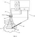
- Fig. 1 illustrates a conventional ultrasound imaging system in combination with a localization system 100.
- the conventional ultrasound imaging system in Fig. 1 includes ultrasound imaging probe 101, imaging system processor 103, imaging system interface 104 and display 105. Imaging system processor 103, imaging system interface 104 and display 105 are located within console 102. Console 102 may be used to supervise a medical procedure.
- Ultrasound imaging probe 101 is attached to console 102 by means of a cable as indicated by the connecting arrow.
- Ultrasound imaging probe 101 includes a one or two-dimensional array of ultrasound transceivers (not shown) for transmitting and receiving ultrasound energy from a volume of interest VOI.
- Console 102 may also include electronic driver and receiver circuitry (not shown) that is configured to amplify and/ or to adjust the phase of signals transmitted by or received by ultrasound imaging probe 101, or received by ultrasound detector 109.
- the electronic driver and receiver circuitry may be used to steer the emitted and/ or received ultrasound beam direction.
- the transceiver array may thus be used to generate either a 2D ultrasound image as indicated by imaging plane PLU, or a 3D ultrasound image.
- Console 102 may also include a memory (not shown) for storing programs and applications.
- the memory may for example store ultrasound beam control software that is configured to control the sequence of ultrasound signals transmitted by and/or received by ultrasound imaging probe 101. It is to be noted however that whilst some of the ultrasound imaging system items are described above as being located within console 102, some of these items may alternatively be located within the imaging system probe, as is the case for example in the Philips LUMIFY ultrasound imaging system.
- Localization system 100 that comprises three ultrasound emitters 107a, b, c, arranged on a frame 110, and position triangulation unit 106 is also included Fig. 1 .
- Localization system 100 may be used to determine the position of a medical device such as exemplary medical needle 108 having ultrasound detector 109 attached thereto.
- Ultrasound detector 109 in Fig. 1 may for example be made from a piezoelectric material.
- the ultrasound detector is made from a Polyvinylidene fluoride material, i.e. PVDF, or one of the related materials in the PVDF group that include PVDF co-polymers and PVDF ter-polymers, although other materials are also suitable.
- PVDF Polyvinylidene fluoride material
- Such materials are available in the form of a thin film and are therefore particularly suited to attachment to a medical device, as described in patent application PCT/IB2015/052425 , published as WO2015/155645 .
- Ultrasound detector 109 is preferably adapted for attachment to a medical device using an adhesive layer.
- a snap-fit connector, or a compression fitting connector that mates with a corresponding connector on the medical device may alternatively be used.
- the three ultrasound emitters 107a, b, c in Fig. 1 are arranged in a predetermined, spaced-apart, configuration on frame 110 that is adapted for attachment to ultrasound imaging probe 101.
- the frame may be attached to ultrasound imaging probe 101 by various means including a press-fit connection, a snap fit connection, an elastic strap or using an adhesive.
- the ultrasound emitters 107a, b, c lie in a common plane and are held by the frame alongside the imaging probe. Alternatively the emitters may be arranged to lie along a straight line.
- Ultrasound emitters 107a, b, c may be made from conventional materials such as piezoelectric materials that expand or contract upon application of electrical pulses and thereby emit ultrasound signals.
- the ultrasound emitters are omnidirectional emitters. However, directional or focused emitters that emit ultrasound waves into a cone angle of less than 4 ⁇ steradians may also be used.
- position triangulation unit 106 communicates with the three ultrasound emitters 107a, b, c as illustrated by the interconnecting arrows and is configured to cause each ultrasound emitter to emit ultrasound signals.
- position triangulation unit 106 is connected to the three ultrasound emitters with electrical wire(s), although wireless communication, for example using an optical, infrared, or an RF communication link is also contemplated.
- the ultrasound signals emitted by the ultrasound emitters may include a single pulse or multiple pulses. In principle the use of a single pulse is adequate to allow the position triangulation unit to determine a set of time delays that are used to triangulate the position of the ultrasound detector. Multiple pulses may alternatively be used to improve their detected signal to noise ratio or to improve their discrimination. In either case the pulses may be emitted sequentially or simultaneously by the emitters. When emitted simultaneously, coding may be used to permit ultrasound detector 109 to distinguish between the pulses emitted by each emitter.
- Such coding may take the form of different pulse durations, different pulse frequencies, or different pulse sequences.
- the frequency of pulses emitted by each ultrasound emitter is different to, for example at least twice, or at most half of the pulse frequency of the ultrasound imaging system.
- the ultrasound signals emitted by each of the three ultrasound emitters comprise a frequency of 1 MHz or less. This is significantly less than the approximately 2 - 10 MHz frequencies emitted by a conventional ultrasound imaging system.
- position triangulation unit 106 is adapted to receive, from ultrasound detector 109, signals indicative of ultrasound signals detected by the ultrasound detector; and is further configured to determine, by triangulation, a spatial position of the ultrasound detector 109 relative to the at least three ultrasound emitters 107a, b, c, based on a first set of time delays ⁇ T 1 , ⁇ T 2 , ⁇ T 3 between the emission of an ultrasound signal by each of the at least three ultrasound emitters 107a, b, c and its detection by the ultrasound detector 109.
- Position triangulation unit 106 may for example have an electrical input that is suitable for receiving such signals from ultrasound detector 109.
- the input may for example be a wired input as indicated by the connecting arrows in Fig. 1 .
- a wireless input wherein a communication path is provided by an optical, infrared, or an RF communication link.
- the position triangulation unit may also include analogue to digital conversion electronics (not shown in Fig. 1 ) for interfacing with ultrasound detector 109.
- the time delays ⁇ T 1 , ⁇ T 2 , ⁇ T 3 used by position triangulation unit 106 to triangulate the detector positon may be computed using a timer, for example.
- the timer might be triggered to start counting at a position on the emitted ultrasound emitter signal and triggered to stop counting by a corresponding position on the detected emitter signal.
- the time delays may be computed by correlating the detected ultrasound signal with the emitted ultrasound signal.
- Other techniques, including the use of matched filtering are also suitable for this purpose. Any of these techniques may be implemented by a processor, for example in position triangulation unit 106, or by dedicated electronic circuitry.
- FIG. 2 illustrates an ultrasound probe 201 together with three ultrasound emitters 207a, b, c attached thereto by means of frame 210, together with an ultrasound detector 209. Imaging plane PLU of ultrasound imaging probe 201 is also shown in Fig. 2 .
- three ultrasound emitters 207a, b, c are located in Cartesian coordinate (x, y, z) positions (0,0,0), (W1,0,0) and (W1,W2,0).
- the time delays ⁇ T 1 , ⁇ T 2 and ⁇ T 3 , of ultrasound wave propagation between respective emitters 207a, b, c and ultrasound detector 209 correspond to the lengths of vertices d1 , d2 , d3 that extend from a plane that is defined by the positions of the three ultrasound emitters.
- the lengths of vertices d1 , d2 , d3 can be calculated using the speed of ultrasound wave propagation in the propagation medium.
- the position of detector 209 can be determined in Cartesian coordinate space using Equations 1 - 3 below, in which W1 and W2 represent the relative positions of the emitters as shown in Fig. 2 .
- S x W 1 2 + d 1 2 ⁇ d 3 2 2
- W 1 S y W 2 2 + d 1 2 ⁇ d 2 2 2
- W 2 S z d 1 2 ⁇ S x 2 ⁇ S y 2
- the position of detector 209 relative to the three ultrasound emitters 207a, b, c can be determined by triangulation. Additional emitters not shown in Fig. 2 or Fig. 1 may also be used, for example at position (0,W2,0), in order to improve the accuracy of the triangulation calculation, or to provide redundancy in case one of the signal paths d1 , d2 , d3 is obscured.
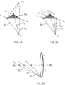
- Fig. 3A illustrates three ultrasound emitters E 1 , E 2 , E 3 that are arranged in a planar configuration
- Fig. 3B illustrates three ultrasound emitters E 1 , E 2 , E 3 that are arranged in a planar configuration and one ultrasound emitter E 4 that lies beyond this plane
- Fig. 3C illustrates three ultrasound emitters E 1 , E 2 , E 3 that are arranged along a straight line AX 1 - AX 2 .
- the minimum number of ultrasound emitters that is required to perform the desired triangulation is three. However, various arrangements of these emitters is possible, which is illustrated in Fig. 3 .
- the ultrasound emitters are arranged in a planar configuration, as indicated by the shaded portion of Fig. 3A that joins the emitters, emitter plane PLE.
- This arrangement improves the tracking of the detector D 1 because the detector's position can be localized to point P 1 based on the time delays ⁇ T 1 , ⁇ T 2 , ⁇ T 3 .
- Point P 1 ' that also satisfies the triangulation calculations can be ruled-out simply with knowledge of which side of the emitter plane the detector lies. In the medical environment contemplated, point P 1 ' can be ruled out since the detector is unlikely to be positioned behind the ultrasound imaging probe. It is also contemplated to use more than three ultrasound emitters in the system of Fig. 1 .
- the arrangement in Fig. 3B includes an out-of-plane emitter E 4 .
- the out-of-plane emitter E 4 can be used either to provide the above-described redundancy, and additionally provides an indication of which side of the shaded plane, emitter plane PLE, the detector lies, thereby eliminating the point P 1 ' solution shown in Fig. 3A .
- 3C illustrates that a linear arrangement of three emitters along straight line AX 1 - AX 2 can be used to localize the position of the detector to an arc A 1 of a circle having radius r about axis AX 1 - AX 2 . Whilst this does not localize the detector position to a particular point, the ability to localize the detector to a position along an arc is still of use in narrowing-down its location.
- the straight line along which the emitters are arranged does not lie in the ultrasound imaging plane.
- localization system 100 may alternatively comprise a single unit. In this case both the three ultrasound emitters and position triangulation unit 106 are adapted for attachment to ultrasound imaging probe 101. This reduces the form factor of localization system 100.
- localization system 100 may be used to determine the position of exemplary medical device 108 with respect to the coordinate system of ultrasound emitters 107a, b, c when ultrasound detector 109 is attached thereto.
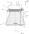
- Fig. 4 illustrates an ultrasound probe 401 together with three ultrasound emitters 407a, b, c attached thereto by means of frame 410, together with a detachable reference volume DRV that comprises a background volume BV and an inclusion or void IN that is within the field of view PLU of the ultrasound imaging probe 401.
- Detachable reference volume DRV is detachable from frame 410 along the thick dashed lines, i.e. a coupling interface as illustrated in Fig. 4 , thus providing the arrangements in Fig.
- the coupling interface may include at least one mechanical registration feature for attaching the detachable reference volume DRV to the frame 110, 410, 510 in a predetermined orientation.
- the mechanical registration feature may be for example a dowel that is attached to the detachable reference volume, and which mates with a corresponding hole in the frame.
- the dowel and the hole may for example have a particular cross section such as a star in order to ensure that the detachable reference volume and the frame can couple only in one orientation.
- a plurality of such dowels may also be used, which case each dowel may have e.g. a circular cross section.
- the predetermined orientation is such that when the detachable reference volume DRV is attached to the frame and the frame is attached to the ultrasound imaging probe, the at least one inclusion or void is configured to provide a corresponding at least one image feature within the field of view PLU of the ultrasound imaging probe.
- Detachable reference volume DRV may be included within a container, for example.
- Inclusion or void IN has an ultrasound acoustic impedance that differs from the ultrasound acoustic impedance of the background volume BV.
- the at least one inclusion or void IN has an ultrasound acoustic impedance that differs by at least 5 %, or at least 10 % or at least 15 % from the ultrasound acoustic impedance of the background volume.
- Detachable reference volume DRV may be subsequently removed after the mapping procedure has taken place so as to avoid interfering with the usual imaging operation of ultrasound imaging probe 101.
- Background volume BV is preferably a material having a similar acoustic impedance to skin, i.e. 1.7 x 10 6 kg m -2 s -1 in order to most closely mimic its usage environment and to avoid excessive ultrasound reflections back to the ultrasound transducers and ultrasound emitters.
- One suitable material for background volume BV is Zerdine, supplied by CIRS of Virginia, US and disclosed in US patent 5196343 . Alternatively this may be provided by water, gelatin, or ultrasound matching gel.
- Suitable materials for inclusion IN include nylon or urethane rubber, or other polymers.
- Inclusion or void IN may be in the form of various shapes, although in principle a single point is sufficient to calibrate the range of the localization system 100 to the range in the field of view of the ultrasound probe PLU.
- Elongated shapes are preferred for inclusion or void IN because these offer the additional possibility of determining the relative rotation between the coordinate system of the tracking system and that of the field of view of the ultrasound probe PLU.
- the field of view PLU of the ultrasound imaging probe 401 extends along a depth axis S in Fig. 4 away from ultrasound imaging probe 401, and the inclusion or void IN is in the form of an elongate shape that extends transversely with respect to the depth axis S.
- Other shapes are also suitable, such as a cross or a star or a t-shape.
- the inclusion or void has a dimension of at least 1 mm in a transverse direction to the depth axis S. This provides a more easily discernible image feature in an ultrasound image.
- the two or more inclusions or voids can be used to calibrate the coordinate system of the tracking system to the field of view of the ultrasound probe with respect to rotation about the depth axis. This aspect of the invention is particularly useful when the field of view of the ultrasound probe is restricted, for example in the form of a plane, when the inclusions or voids may be only partly visible in the planar image due to a large rotational error.
- the relative rotation between the coordinate system of the localization system 100 and the field of view of the ultrasound probe PLU may for example be determined by measuring the relative lengths of each inclusion or void in the field of view of the ultrasound imaging probe.
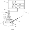
- Fig. 5 illustrates a conventional ultrasound imaging system in combination with a localization system 500.
- Fig. 5 includes image fusion unit 511.
- the conventional ultrasound imaging system in Fig. 5 includes ultrasound imaging probe 501, imaging system processor 503, imaging system interface 504 and display 505.
- Imaging system processor 503, imaging system interface 504 and display 505 are located within console 502.
- Ultrasound imaging probe 501 includes a one or two-dimensional array of ultrasound transceivers (not shown) for transmitting and receiving ultrasound energy from a volume of interest VOI.
- Console 502 may also include electronic driver and receiver circuitry (not shown) that is configured to amplify and/ or to adjust the phase of signals transmitted by or received by ultrasound imaging probe 501, or received by ultrasound detector 509.
- the electronic driver and receiver circuitry may be used to steer the emitted and/ or received ultrasound beam direction.
- the transceiver array may thus be used to generate either a 2D ultrasound image as indicated by imaging plane PLU, or a 3D ultrasound image.
- Console 502 may also include a memory (not shown) for storing programs and applications.
- a localization system 500 that comprises three ultrasound emitters 507a, b, c, arranged on a frame 510, and position triangulation unit 506 is also included Fig. 5 .
- Localization system 500 may be used to determine the position of a medical device such as exemplary medical needle 508 having ultrasound detector 509 attached thereto.
- image fusion unit 511 in Fig. 5 is in communication with imaging system processor 503 and position triangulation unit 506.
- Image fusion unit 511 is configured to generate a fused image representation based on the ultrasound image representation and the spatial position of the ultrasound detector. Techniques for providing the fused image representation are well known in the image processing field.
- Image fusion unit 511 may comprise one or more processors that perform the desired image fusion. The image fusion may alternatively be carried out by imaging system processor 503, or the same processor that performs the function of position triangulation unit 506.
- the spatial position of the ultrasound detector may for example be indicated by a marker such as a cross, a circle, a crosshair, an arrow, a pointer or indeed a change in color of the ultrasound image.
- the fused image may also be provided in the form of a partially-transparent marker which allows viewing of the portion of ultrasound image underneath it.
- imaging system processor 503 When the image generated by imaging system processor 503 is a 2D ultrasound image, it is also contemplated to indicate, in the 2D ultrasound image, which side of the ultrasound image plane the ultrasound detector lies. This is particularly useful when the detector lies beyond the ultrasound image plane, i.e. it lies "out-of-plane", because it alerts a physician to tilt the ultrasound image probe in order to bring the detector back into the ultrasound image plane, i.e. "in-plane”. In so doing the physician can visualize the exact position of the detector with respect to the ultrasound image. In this arrangement, in localization system 500 illustrated in Fig. 5 , imaging system processor 503 is configured to reconstruct an ultrasound image representation of a plane PLU that intersects a volume of interest VOI.
- position triangulation unit 506 is configured to provide, in the fused image, an indication of the side of the plane on which the ultrasound detector is located when the ultrasound detector lies beyond the plane of the ultrasound image representation. This is possible with the arrangement in Fig. 5 because localization system 500 is not limited to in-plane tracking of the position of detector 509, and thus the actual detector positon in relation to plane PLU is readily determined.
- Such an indication of the side of the plane on which the ultrasound detector is located may take the form of a textual indication in the fused image, for example "above plane” or “below plane", an arrow showing the direction in which the probe must be tilted in order to bring the ultrasound detector back in-plane, or a distance between the ultrasound detector and the plane; preferably the shortest distance to the plane. It is also contemplated to provide the indication in the form of a marker, such as a circle or a cross, at a point in the 2D ultrasound image that is nearest to the ultrasound detector, wherein the marker has a size that varies in accordance with the out-of-plane distance to the ultrasound detector.
- a marker such as a circle or a cross
- a second ultrasound detector may also be attached to the medical device 108, 508 of Fig. 1 or Fig. 5 .
- the position triangulation unit 106, 506 is further adapted for receiving, from the second ultrasound detector, signals indicative of ultrasound signals detected by the second ultrasound detector.
- the position triangulation unit is configured to determine, by triangulation, a spatial position of the second ultrasound detector relative to the at least three ultrasound emitters 107a, b, c, 507a, b, c based on a second set of time delays ⁇ T 21 , ⁇ T 22 , ⁇ T 23 between the emission of an ultrasound signal by each of the at least three ultrasound emitters and its detection by the second ultrasound detector.
- the position triangulation unit 106, 506 is further configured to determine a trajectory between the ultrasound detector 109, 509 and the second ultrasound detector based on the spatial positions of the ultrasound detector and the second ultrasound detector.
- the relative positions of the two ultrasound detectors inherently define a trajectory.
- this trajectory may thus be used to indicate a trajectory of the medical device.
- This embodiment finds particular application in medical devices such as needles that have an axis, and where it is valuable to determine the trajectory of that axis. This may subsequently be indicated in an ultrasound image generated by the image fusion unit. In medical procedures using a needle it is valuable to know the needle trajectory in order to determine whether insertion of the needle at its present position will result in the needle tip position ending-up at a desired point in a volume of interest.
- a calibration method is disclosed that may be used with the system in Fig. 1 or Fig. 5 . It may also be used in combination with the other embodiments described herein.
- the calibration method may be used to calibrate the coordinate system of the tracking system to the field of view of the ultrasound probe.
- the mapping may also be used to determine the position of the detector 109, 509, with respect to the field of view PLU of the ultrasound probe 101, 501.
- the ultrasound probe has a field of view that is defined by a coordinate system, and ultrasound image features are mapped into this field of view or coordinate system by the ultrasound image reconstruction process.
- the tracking system likewise has a coordinate system which is defined in relation to the positions of its ultrasound emitters 107a, b, c, 507a, b, c.
- One method of aligning the two coordinate systems could be to ensure that the ultrasound emitters are in an exact position in relation to the ultrasound transceiver array.
- Such an alignment is tricky to achieve, particularly when the frame is retro-fitted to an ultrasound probe that is already in service in the field. This may thus result in a rotational or a range error in the detector position as determined by the position triangulation unit.
- the calibration method of this embodiment provides a mapping that accounts for such misalignments.
- the calibration method includes the steps of: i) providing a measured ultrasound image representation corresponding to the field of view PLU of the ultrasound imaging probe 501 based on ultrasound signals transmitted and received by the ultrasound imaging probe 501, and wherein the measured ultrasound image representation includes at least a portion of the at least one image feature; ii) providing a predicted ultrasound image representation corresponding to a predicted field of view PLU of the ultrasound imaging probe 501 based on a position of the at least one inclusion or void IN in relation to the at least three ultrasound emitters 107a, b, c, 507a, b, c; and iii) determining a translation between the predicted ultrasound image representation and the measured ultrasound image representation for mapping the spatial position of the ultrasound detector 109, 509 as determined by the position triangulation unit 106, 506 to the field of view PLU of the ultrasound imaging probe 501.
- the predicted ultrasound image representation includes at least part of the image feature corresponding to the inclusion or void IN, and is the image that would be generated by the ultrasound imaging system when the frame, i.e. ultrasound emitters, is positioned respective the transceiver array, i.e. the ultrasound imaging probe, such that the coordinate system of the ultrasound imaging probe is aligned with the coordinate system of the tracking system.
- the predicted ultrasound image representation corresponds to the field of view, including part of the inclusion, when the coordinate systems are aligned.
- mapping may include operations such as rotation, scaling, translation, and other affine transformations.
- this mapping can be applied to each point within the coordinate system of the tracking system in order to align measured positions in the coordinate system of the tracking system to measured positions in the field of view of the ultrasound imaging probe.
- a computer program product comprises instructions which when executed on a processor cause the processor to carry out the calibration method steps described above.
- the computer program product may be provided by dedicated hardware as well as hardware capable of executing software in association with appropriate software.
- the functions can be provided by a single dedicated processor, by a single shared processor, or by a plurality of individual processors, some of which can be shared.
- explicit use of the term "processor” or “controller” should not be construed to refer exclusively to hardware capable of executing software, and can implicitly include, without limitation, digital signal processor "DSP” hardware, read only memory “ROM” for storing software, random access memory “RAM”, non-volatile storage, etc.
- embodiments of the present invention can take the form of a computer program product accessible from a computer-usable or computer-readable storage medium providing program code for use by or in connection with a computer or any instruction execution system.
- a computer-usable or computer readable storage medium can be any apparatus that may include, store, communicate, propagate, or transport the program for use by or in connection with the instruction execution system, apparatus, or device.
- the medium can be an electronic, magnetic, optical, electromagnetic, infrared, or semiconductor system, or apparatus or device, or a propagation medium.
- Examples of a computer-readable medium include a semiconductor or solid state memory, magnetic tape, a removable computer diskette, a random access memory "RAM”, a read-only memory “ROM”, a rigid magnetic disk and an optical disk.
- Current examples of optical disks include compact disk - read only memory "CD-ROM”, compact disk - read/write “CD-R/W”, Blu-RayTM and DVD.
Landscapes
- Health & Medical Sciences (AREA)
- Life Sciences & Earth Sciences (AREA)
- Engineering & Computer Science (AREA)
- Surgery (AREA)
- Animal Behavior & Ethology (AREA)
- Veterinary Medicine (AREA)
- Biomedical Technology (AREA)
- Heart & Thoracic Surgery (AREA)
- Medical Informatics (AREA)
- Molecular Biology (AREA)
- Nuclear Medicine, Radiotherapy & Molecular Imaging (AREA)
- General Health & Medical Sciences (AREA)
- Public Health (AREA)
- Physics & Mathematics (AREA)
- Biophysics (AREA)
- Pathology (AREA)
- Radiology & Medical Imaging (AREA)
- Robotics (AREA)
- General Physics & Mathematics (AREA)
- Radar, Positioning & Navigation (AREA)
- Remote Sensing (AREA)
- Ultra Sonic Daignosis Equipment (AREA)
- Measurement Of Velocity Or Position Using Acoustic Or Ultrasonic Waves (AREA)
Applications Claiming Priority (2)
| Application Number | Priority Date | Filing Date | Title |
|---|---|---|---|
| EP15201890 | 2015-12-22 | ||
| PCT/EP2016/080708 WO2017108490A1 (en) | 2015-12-22 | 2016-12-13 | Ultrasound based tracking |
Publications (2)
| Publication Number | Publication Date |
|---|---|
| EP3394634A1 EP3394634A1 (en) | 2018-10-31 |
| EP3394634B1 true EP3394634B1 (en) | 2019-07-31 |
Family
ID=54979544
Family Applications (1)
| Application Number | Title | Priority Date | Filing Date |
|---|---|---|---|
| EP16808713.8A Not-in-force EP3394634B1 (en) | 2015-12-22 | 2016-12-13 | Ultrasound based tracking |
Country Status (5)
| Country | Link |
|---|---|
| US (2) | US11413011B2 (enExample) |
| EP (1) | EP3394634B1 (enExample) |
| JP (1) | JP6636639B2 (enExample) |
| CN (1) | CN108474837A (enExample) |
| WO (1) | WO2017108490A1 (enExample) |
Families Citing this family (18)
| Publication number | Priority date | Publication date | Assignee | Title |
|---|---|---|---|---|
| US11432875B2 (en) * | 2017-09-28 | 2022-09-06 | Siemens Medical Solutions Usa, Inc. | Left atrial appendage closure guidance in medical imaging |
| US11638569B2 (en) | 2018-06-08 | 2023-05-02 | Rutgers, The State University Of New Jersey | Computer vision systems and methods for real-time needle detection, enhancement and localization in ultrasound |
| CN109259793A (zh) * | 2018-07-11 | 2019-01-25 | 浙江京新术派医疗科技有限公司 | 超声校准系统、方法、电子设备及存储介质 |
| EP3632333A1 (en) * | 2018-10-05 | 2020-04-08 | Koninklijke Philips N.V. | Interventional device positioning respective an ultrasound image plane |
| WO2020036968A1 (en) * | 2018-08-13 | 2020-02-20 | Rutgers, The State University Of New Jersey | Computer vision systems and methods for real-time localization of needles in ultrasound images |
| JP7168474B2 (ja) * | 2019-01-31 | 2022-11-09 | 富士フイルムヘルスケア株式会社 | 超音波撮像装置、治療支援システム、及び、画像処理方法 |
| CN111789630B (zh) * | 2019-04-08 | 2023-06-20 | 中慧医学成像有限公司 | 超声探头三维空间信息测量装置 |
| US11486961B2 (en) * | 2019-06-14 | 2022-11-01 | Chirp Microsystems | Object-localization and tracking using ultrasonic pulses with reflection rejection |
| BR112022000056A2 (pt) * | 2019-07-05 | 2022-02-22 | Cianna Medical Inc | Sistemas e métodos para localizar marcadores em um corpo |
| CN110477842B (zh) * | 2019-08-26 | 2020-07-24 | 清华大学 | 体内检测系统和方法 |
| CN111329586B (zh) * | 2020-02-17 | 2021-05-11 | 南京航空航天大学 | 基于超声定位带的体内器械定位跟踪系统 |
| US11892431B2 (en) * | 2020-03-31 | 2024-02-06 | ThunderTech Inc. | Acoustic array detection and imaging |
| DE102020204985A1 (de) | 2020-04-21 | 2021-10-21 | Siemens Healthcare Gmbh | Steuerung eines robotisch bewegten medizinischen Objekts |
| CN114052774B (zh) * | 2020-07-29 | 2025-10-17 | 深圳迈瑞生物医疗电子股份有限公司 | 超声成像设备的供电装置、超声成像系统 |
| JP7461246B2 (ja) * | 2020-08-08 | 2024-04-03 | 日本電波工業株式会社 | 超音波探触子及びその製造方法 |
| JP7461247B2 (ja) * | 2020-08-08 | 2024-04-03 | 日本電波工業株式会社 | 超音波探触子 |
| CN112472132A (zh) * | 2020-12-18 | 2021-03-12 | 佟小龙 | 一种定位成像区域的装置、方法及医学成像装置 |
| US12426961B2 (en) * | 2023-09-14 | 2025-09-30 | GE Precision Healthcare LLC | System and method for automatic medical device placement in an anatomical structure using a locking mechanism |
Family Cites Families (31)
| Publication number | Priority date | Publication date | Assignee | Title |
|---|---|---|---|---|
| JPS637214Y2 (enExample) * | 1980-10-15 | 1988-03-01 | ||
| US4567896A (en) * | 1984-01-20 | 1986-02-04 | Elscint, Inc. | Method and apparatus for calibrating a biopsy attachment for ultrasonic imaging apparatus |
| US5196343A (en) | 1990-10-04 | 1993-03-23 | Zerhouni Moustafa B | Ultrasonic calibration material and method |
| US5817022A (en) | 1995-03-28 | 1998-10-06 | Sonometrics Corporation | System for displaying a 2-D ultrasound image within a 3-D viewing environment |
| US5515853A (en) | 1995-03-28 | 1996-05-14 | Sonometrics Corporation | Three-dimensional digital ultrasound tracking system |
| US6720766B2 (en) * | 1995-04-14 | 2004-04-13 | Kevin J. Parker | Thin film phantoms and phantom systems |
| EP0845959A4 (en) | 1995-07-16 | 1998-09-30 | Ultra Guide Ltd | HAND-FREE DRAWING A NEEDLE GUIDE |
| US7549960B2 (en) * | 1999-03-11 | 2009-06-23 | Biosense, Inc. | Implantable and insertable passive tags |
| US6338716B1 (en) * | 1999-11-24 | 2002-01-15 | Acuson Corporation | Medical diagnostic ultrasonic transducer probe and imaging system for use with a position and orientation sensor |
| US6685644B2 (en) * | 2001-04-24 | 2004-02-03 | Kabushiki Kaisha Toshiba | Ultrasound diagnostic apparatus |
| US6719700B1 (en) | 2002-12-13 | 2004-04-13 | Scimed Life Systems, Inc. | Ultrasound ranging for localization of imaging transducer |
| US7713210B2 (en) * | 2004-11-23 | 2010-05-11 | St. Jude Medical, Atrial Fibrillation Division, Inc. | Method and apparatus for localizing an ultrasound catheter |
| US20060241432A1 (en) * | 2005-02-15 | 2006-10-26 | Vanderbilt University | Method and apparatus for calibration, tracking and volume construction data for use in image-guided procedures |
| US10143398B2 (en) * | 2005-04-26 | 2018-12-04 | Biosense Webster, Inc. | Registration of ultrasound data with pre-acquired image |
| JP5629101B2 (ja) * | 2010-03-09 | 2014-11-19 | 株式会社日立メディコ | 治療支援装置及び治療支援システム |
| EP2584965B1 (en) | 2010-06-28 | 2016-04-13 | Koninklijke Philips N.V. | Real-time quality control of em calibration |
| US9332960B2 (en) * | 2011-02-03 | 2016-05-10 | Given Imaging Ltd. | System and method for determining location and orientation of a device in-vivo |
| JP6053766B2 (ja) | 2011-06-13 | 2016-12-27 | コーニンクレッカ フィリップス エヌ ヴェKoninklijke Philips N.V. | 二次元撮像プローブを用いる三次元針位置特定 |
| US8887551B2 (en) | 2011-09-06 | 2014-11-18 | Trig Medical Ltd. | Calibration of instrument relative to ultrasonic probe |
| KR102176193B1 (ko) * | 2012-08-10 | 2020-11-09 | 마우이 이미징, 인코포레이티드 | 다중 어퍼처 초음파 프로브들의 교정 |
| JP2014124319A (ja) * | 2012-12-26 | 2014-07-07 | Tokyo Univ Of Agriculture & Technology | 超音波キャリブレーションシステム及び超音波キャリブレーション方法 |
| US20150374343A1 (en) * | 2013-02-11 | 2015-12-31 | Koninklijke Philips N.V. | Ultrasound imaging system and method |
| EP2858574A1 (en) * | 2013-03-15 | 2015-04-15 | Chison Medical Imaging Co., Ltd. | Systems and methods to detect and present interventional devices via ultrasound imaging |
| US9753307B2 (en) | 2013-03-15 | 2017-09-05 | Hoya Corporation | Spectacle lens, manufacturing method thereof and lens supply system |
| US20140343425A1 (en) | 2013-05-17 | 2014-11-20 | University Of Florida Research Foundation, Incorporated | Enhanced ultrasound imaging interpretation and navigation |
| JP6282934B2 (ja) * | 2013-06-11 | 2018-02-21 | キヤノンメディカルシステムズ株式会社 | 超音波診断装置及び医用画像診断装置 |
| US20150173723A1 (en) | 2013-12-20 | 2015-06-25 | General Electric Company | Method and system for automatic needle recalibration detection |
| US10507006B2 (en) | 2013-12-27 | 2019-12-17 | General Electric Company | System and method for tracking an invasive device using ultrasound position signals |
| CN105873521B (zh) | 2014-01-02 | 2020-09-15 | 皇家飞利浦有限公司 | 相对超声成像平面的仪器对准和跟踪 |
| EP3128931B1 (en) | 2014-04-10 | 2020-06-10 | Koninklijke Philips N.V. | Needle with piezoelectric polymer sensors |
| US10675006B2 (en) * | 2015-05-15 | 2020-06-09 | Siemens Medical Solutions Usa, Inc. | Registration for multi-modality medical imaging fusion with narrow field of view |
-
2016
- 2016-12-13 JP JP2018532301A patent/JP6636639B2/ja not_active Expired - Fee Related
- 2016-12-13 US US16/063,858 patent/US11413011B2/en active Active
- 2016-12-13 CN CN201680075778.6A patent/CN108474837A/zh active Pending
- 2016-12-13 WO PCT/EP2016/080708 patent/WO2017108490A1/en not_active Ceased
- 2016-12-13 EP EP16808713.8A patent/EP3394634B1/en not_active Not-in-force
-
2022
- 2022-07-08 US US17/860,314 patent/US11633171B2/en active Active
Non-Patent Citations (1)
| Title |
|---|
| None * |
Also Published As
| Publication number | Publication date |
|---|---|
| US11413011B2 (en) | 2022-08-16 |
| EP3394634A1 (en) | 2018-10-31 |
| JP6636639B2 (ja) | 2020-01-29 |
| JP2019505270A (ja) | 2019-02-28 |
| US20220346752A1 (en) | 2022-11-03 |
| US20180368807A1 (en) | 2018-12-27 |
| WO2017108490A1 (en) | 2017-06-29 |
| US11633171B2 (en) | 2023-04-25 |
| CN108474837A (zh) | 2018-08-31 |
Similar Documents
| Publication | Publication Date | Title |
|---|---|---|
| US11633171B2 (en) | Ultrasound based tracking system using triangulation and spatial positioning with detachable reference frame and ultrasound emitters | |
| US11604249B2 (en) | Interventional device recognition | |
| US12004899B2 (en) | Tracking a feature of an interventional device | |
| EP2717772B1 (en) | Three-dimensional needle localization with a two-dimensional imaging probe | |
| CN108366780B (zh) | 介入设备及包括其的超声跟踪单元 | |
| WO2020030557A1 (en) | Tracking an interventional device respective an ultrasound image plane | |
| WO2020030746A1 (en) | Interventional device positioning using ultrasound signals | |
| EP3833263B1 (en) | Tracking an interventional device respective an ultrasound image plane | |
| EP3833265B1 (en) | Interventional device positioning respective an ultrasound image plane | |
| EP3833266B1 (en) | Interventional device positioning using ultrasound signals |
Legal Events
| Date | Code | Title | Description |
|---|---|---|---|
| STAA | Information on the status of an ep patent application or granted ep patent |
Free format text: STATUS: UNKNOWN |
|
| STAA | Information on the status of an ep patent application or granted ep patent |
Free format text: STATUS: THE INTERNATIONAL PUBLICATION HAS BEEN MADE |
|
| PUAI | Public reference made under article 153(3) epc to a published international application that has entered the european phase |
Free format text: ORIGINAL CODE: 0009012 |
|
| STAA | Information on the status of an ep patent application or granted ep patent |
Free format text: STATUS: REQUEST FOR EXAMINATION WAS MADE |
|
| 17P | Request for examination filed |
Effective date: 20180723 |
|
| AK | Designated contracting states |
Kind code of ref document: A1 Designated state(s): AL AT BE BG CH CY CZ DE DK EE ES FI FR GB GR HR HU IE IS IT LI LT LU LV MC MK MT NL NO PL PT RO RS SE SI SK SM TR |
|
| AX | Request for extension of the european patent |
Extension state: BA ME |
|
| GRAP | Despatch of communication of intention to grant a patent |
Free format text: ORIGINAL CODE: EPIDOSNIGR1 |
|
| STAA | Information on the status of an ep patent application or granted ep patent |
Free format text: STATUS: GRANT OF PATENT IS INTENDED |
|
| DAV | Request for validation of the european patent (deleted) | ||
| DAX | Request for extension of the european patent (deleted) | ||
| INTG | Intention to grant announced |
Effective date: 20190218 |
|
| GRAS | Grant fee paid |
Free format text: ORIGINAL CODE: EPIDOSNIGR3 |
|
| GRAA | (expected) grant |
Free format text: ORIGINAL CODE: 0009210 |
|
| STAA | Information on the status of an ep patent application or granted ep patent |
Free format text: STATUS: THE PATENT HAS BEEN GRANTED |
|
| AK | Designated contracting states |
Kind code of ref document: B1 Designated state(s): AL AT BE BG CH CY CZ DE DK EE ES FI FR GB GR HR HU IE IS IT LI LT LU LV MC MK MT NL NO PL PT RO RS SE SI SK SM TR |
|
| REG | Reference to a national code |
Ref country code: CH Ref legal event code: EP Ref country code: GB Ref legal event code: FG4D |
|
| REG | Reference to a national code |
Ref country code: AT Ref legal event code: REF Ref document number: 1161499 Country of ref document: AT Kind code of ref document: T Effective date: 20190815 |
|
| REG | Reference to a national code |
Ref country code: IE Ref legal event code: FG4D |
|
| REG | Reference to a national code |
Ref country code: DE Ref legal event code: R096 Ref document number: 602016017881 Country of ref document: DE |
|
| REG | Reference to a national code |
Ref country code: NL Ref legal event code: MP Effective date: 20190731 |
|
| REG | Reference to a national code |
Ref country code: LT Ref legal event code: MG4D |
|
| REG | Reference to a national code |
Ref country code: AT Ref legal event code: MK05 Ref document number: 1161499 Country of ref document: AT Kind code of ref document: T Effective date: 20190731 |
|
| PG25 | Lapsed in a contracting state [announced via postgrant information from national office to epo] |
Ref country code: LT Free format text: LAPSE BECAUSE OF FAILURE TO SUBMIT A TRANSLATION OF THE DESCRIPTION OR TO PAY THE FEE WITHIN THE PRESCRIBED TIME-LIMIT Effective date: 20190731 Ref country code: NL Free format text: LAPSE BECAUSE OF FAILURE TO SUBMIT A TRANSLATION OF THE DESCRIPTION OR TO PAY THE FEE WITHIN THE PRESCRIBED TIME-LIMIT Effective date: 20190731 Ref country code: BG Free format text: LAPSE BECAUSE OF FAILURE TO SUBMIT A TRANSLATION OF THE DESCRIPTION OR TO PAY THE FEE WITHIN THE PRESCRIBED TIME-LIMIT Effective date: 20191031 Ref country code: FI Free format text: LAPSE BECAUSE OF FAILURE TO SUBMIT A TRANSLATION OF THE DESCRIPTION OR TO PAY THE FEE WITHIN THE PRESCRIBED TIME-LIMIT Effective date: 20190731 Ref country code: NO Free format text: LAPSE BECAUSE OF FAILURE TO SUBMIT A TRANSLATION OF THE DESCRIPTION OR TO PAY THE FEE WITHIN THE PRESCRIBED TIME-LIMIT Effective date: 20191031 Ref country code: AT Free format text: LAPSE BECAUSE OF FAILURE TO SUBMIT A TRANSLATION OF THE DESCRIPTION OR TO PAY THE FEE WITHIN THE PRESCRIBED TIME-LIMIT Effective date: 20190731 Ref country code: PT Free format text: LAPSE BECAUSE OF FAILURE TO SUBMIT A TRANSLATION OF THE DESCRIPTION OR TO PAY THE FEE WITHIN THE PRESCRIBED TIME-LIMIT Effective date: 20191202 Ref country code: SE Free format text: LAPSE BECAUSE OF FAILURE TO SUBMIT A TRANSLATION OF THE DESCRIPTION OR TO PAY THE FEE WITHIN THE PRESCRIBED TIME-LIMIT Effective date: 20190731 Ref country code: HR Free format text: LAPSE BECAUSE OF FAILURE TO SUBMIT A TRANSLATION OF THE DESCRIPTION OR TO PAY THE FEE WITHIN THE PRESCRIBED TIME-LIMIT Effective date: 20190731 |
|
| PG25 | Lapsed in a contracting state [announced via postgrant information from national office to epo] |
Ref country code: RS Free format text: LAPSE BECAUSE OF FAILURE TO SUBMIT A TRANSLATION OF THE DESCRIPTION OR TO PAY THE FEE WITHIN THE PRESCRIBED TIME-LIMIT Effective date: 20190731 Ref country code: LV Free format text: LAPSE BECAUSE OF FAILURE TO SUBMIT A TRANSLATION OF THE DESCRIPTION OR TO PAY THE FEE WITHIN THE PRESCRIBED TIME-LIMIT Effective date: 20190731 Ref country code: AL Free format text: LAPSE BECAUSE OF FAILURE TO SUBMIT A TRANSLATION OF THE DESCRIPTION OR TO PAY THE FEE WITHIN THE PRESCRIBED TIME-LIMIT Effective date: 20190731 Ref country code: IS Free format text: LAPSE BECAUSE OF FAILURE TO SUBMIT A TRANSLATION OF THE DESCRIPTION OR TO PAY THE FEE WITHIN THE PRESCRIBED TIME-LIMIT Effective date: 20191130 Ref country code: GR Free format text: LAPSE BECAUSE OF FAILURE TO SUBMIT A TRANSLATION OF THE DESCRIPTION OR TO PAY THE FEE WITHIN THE PRESCRIBED TIME-LIMIT Effective date: 20191101 Ref country code: ES Free format text: LAPSE BECAUSE OF FAILURE TO SUBMIT A TRANSLATION OF THE DESCRIPTION OR TO PAY THE FEE WITHIN THE PRESCRIBED TIME-LIMIT Effective date: 20190731 |
|
| RAP2 | Party data changed (patent owner data changed or rights of a patent transferred) |
Owner name: KONINKLIJKE PHILIPS N.V. |
|
| PG25 | Lapsed in a contracting state [announced via postgrant information from national office to epo] |
Ref country code: TR Free format text: LAPSE BECAUSE OF FAILURE TO SUBMIT A TRANSLATION OF THE DESCRIPTION OR TO PAY THE FEE WITHIN THE PRESCRIBED TIME-LIMIT Effective date: 20190731 |
|
| PG25 | Lapsed in a contracting state [announced via postgrant information from national office to epo] |
Ref country code: DK Free format text: LAPSE BECAUSE OF FAILURE TO SUBMIT A TRANSLATION OF THE DESCRIPTION OR TO PAY THE FEE WITHIN THE PRESCRIBED TIME-LIMIT Effective date: 20190731 Ref country code: EE Free format text: LAPSE BECAUSE OF FAILURE TO SUBMIT A TRANSLATION OF THE DESCRIPTION OR TO PAY THE FEE WITHIN THE PRESCRIBED TIME-LIMIT Effective date: 20190731 Ref country code: PL Free format text: LAPSE BECAUSE OF FAILURE TO SUBMIT A TRANSLATION OF THE DESCRIPTION OR TO PAY THE FEE WITHIN THE PRESCRIBED TIME-LIMIT Effective date: 20190731 Ref country code: IT Free format text: LAPSE BECAUSE OF FAILURE TO SUBMIT A TRANSLATION OF THE DESCRIPTION OR TO PAY THE FEE WITHIN THE PRESCRIBED TIME-LIMIT Effective date: 20190731 Ref country code: RO Free format text: LAPSE BECAUSE OF FAILURE TO SUBMIT A TRANSLATION OF THE DESCRIPTION OR TO PAY THE FEE WITHIN THE PRESCRIBED TIME-LIMIT Effective date: 20190731 |
|
| PG25 | Lapsed in a contracting state [announced via postgrant information from national office to epo] |
Ref country code: SM Free format text: LAPSE BECAUSE OF FAILURE TO SUBMIT A TRANSLATION OF THE DESCRIPTION OR TO PAY THE FEE WITHIN THE PRESCRIBED TIME-LIMIT Effective date: 20190731 Ref country code: IS Free format text: LAPSE BECAUSE OF FAILURE TO SUBMIT A TRANSLATION OF THE DESCRIPTION OR TO PAY THE FEE WITHIN THE PRESCRIBED TIME-LIMIT Effective date: 20200224 Ref country code: CZ Free format text: LAPSE BECAUSE OF FAILURE TO SUBMIT A TRANSLATION OF THE DESCRIPTION OR TO PAY THE FEE WITHIN THE PRESCRIBED TIME-LIMIT Effective date: 20190731 Ref country code: SK Free format text: LAPSE BECAUSE OF FAILURE TO SUBMIT A TRANSLATION OF THE DESCRIPTION OR TO PAY THE FEE WITHIN THE PRESCRIBED TIME-LIMIT Effective date: 20190731 |
|
| REG | Reference to a national code |
Ref country code: DE Ref legal event code: R097 Ref document number: 602016017881 Country of ref document: DE |
|
| PLBE | No opposition filed within time limit |
Free format text: ORIGINAL CODE: 0009261 |
|
| STAA | Information on the status of an ep patent application or granted ep patent |
Free format text: STATUS: NO OPPOSITION FILED WITHIN TIME LIMIT |
|
| PG2D | Information on lapse in contracting state deleted |
Ref country code: IS |
|
| PG25 | Lapsed in a contracting state [announced via postgrant information from national office to epo] |
Ref country code: IS Free format text: LAPSE BECAUSE OF FAILURE TO SUBMIT A TRANSLATION OF THE DESCRIPTION OR TO PAY THE FEE WITHIN THE PRESCRIBED TIME-LIMIT Effective date: 20191030 |
|
| REG | Reference to a national code |
Ref country code: CH Ref legal event code: PL |
|
| 26N | No opposition filed |
Effective date: 20200603 |
|
| REG | Reference to a national code |
Ref country code: BE Ref legal event code: MM Effective date: 20191231 |
|
| PG25 | Lapsed in a contracting state [announced via postgrant information from national office to epo] |
Ref country code: MC Free format text: LAPSE BECAUSE OF FAILURE TO SUBMIT A TRANSLATION OF THE DESCRIPTION OR TO PAY THE FEE WITHIN THE PRESCRIBED TIME-LIMIT Effective date: 20190731 |
|
| PG25 | Lapsed in a contracting state [announced via postgrant information from national office to epo] |
Ref country code: IE Free format text: LAPSE BECAUSE OF NON-PAYMENT OF DUE FEES Effective date: 20191213 Ref country code: LU Free format text: LAPSE BECAUSE OF NON-PAYMENT OF DUE FEES Effective date: 20191213 Ref country code: FR Free format text: LAPSE BECAUSE OF NON-PAYMENT OF DUE FEES Effective date: 20191231 |
|
| PG25 | Lapsed in a contracting state [announced via postgrant information from national office to epo] |
Ref country code: CH Free format text: LAPSE BECAUSE OF NON-PAYMENT OF DUE FEES Effective date: 20191231 Ref country code: LI Free format text: LAPSE BECAUSE OF NON-PAYMENT OF DUE FEES Effective date: 20191231 Ref country code: BE Free format text: LAPSE BECAUSE OF NON-PAYMENT OF DUE FEES Effective date: 20191231 |
|
| PG25 | Lapsed in a contracting state [announced via postgrant information from national office to epo] |
Ref country code: CY Free format text: LAPSE BECAUSE OF FAILURE TO SUBMIT A TRANSLATION OF THE DESCRIPTION OR TO PAY THE FEE WITHIN THE PRESCRIBED TIME-LIMIT Effective date: 20190731 |
|
| PG25 | Lapsed in a contracting state [announced via postgrant information from national office to epo] |
Ref country code: HU Free format text: LAPSE BECAUSE OF FAILURE TO SUBMIT A TRANSLATION OF THE DESCRIPTION OR TO PAY THE FEE WITHIN THE PRESCRIBED TIME-LIMIT; INVALID AB INITIO Effective date: 20161213 Ref country code: MT Free format text: LAPSE BECAUSE OF FAILURE TO SUBMIT A TRANSLATION OF THE DESCRIPTION OR TO PAY THE FEE WITHIN THE PRESCRIBED TIME-LIMIT Effective date: 20190731 |
|
| PG25 | Lapsed in a contracting state [announced via postgrant information from national office to epo] |
Ref country code: SI Free format text: LAPSE BECAUSE OF FAILURE TO SUBMIT A TRANSLATION OF THE DESCRIPTION OR TO PAY THE FEE WITHIN THE PRESCRIBED TIME-LIMIT Effective date: 20190731 |
|
| PG25 | Lapsed in a contracting state [announced via postgrant information from national office to epo] |
Ref country code: MK Free format text: LAPSE BECAUSE OF FAILURE TO SUBMIT A TRANSLATION OF THE DESCRIPTION OR TO PAY THE FEE WITHIN THE PRESCRIBED TIME-LIMIT Effective date: 20190731 |
|
| PGFP | Annual fee paid to national office [announced via postgrant information from national office to epo] |
Ref country code: GB Payment date: 20231219 Year of fee payment: 8 |
|
| REG | Reference to a national code |
Ref country code: DE Ref legal event code: R084 Ref document number: 602016017881 Country of ref document: DE |
|
| PGFP | Annual fee paid to national office [announced via postgrant information from national office to epo] |
Ref country code: DE Payment date: 20231227 Year of fee payment: 8 |
|
| REG | Reference to a national code |
Ref country code: GB Ref legal event code: 746 Effective date: 20240627 |
|
| REG | Reference to a national code |
Ref country code: DE Ref legal event code: R119 Ref document number: 602016017881 Country of ref document: DE |
|
| GBPC | Gb: european patent ceased through non-payment of renewal fee |
Effective date: 20241213 |
|
| PG25 | Lapsed in a contracting state [announced via postgrant information from national office to epo] |
Ref country code: DE Free format text: LAPSE BECAUSE OF NON-PAYMENT OF DUE FEES Effective date: 20250701 |
|
| PG25 | Lapsed in a contracting state [announced via postgrant information from national office to epo] |
Ref country code: GB Free format text: LAPSE BECAUSE OF NON-PAYMENT OF DUE FEES Effective date: 20241213 |