EP3394580B1 - Wärmeflusssensor - Google Patents
Wärmeflusssensor Download PDFInfo
- Publication number
- EP3394580B1 EP3394580B1 EP16826324.2A EP16826324A EP3394580B1 EP 3394580 B1 EP3394580 B1 EP 3394580B1 EP 16826324 A EP16826324 A EP 16826324A EP 3394580 B1 EP3394580 B1 EP 3394580B1
- Authority
- EP
- European Patent Office
- Prior art keywords
- thermistor
- heat
- temperature
- flow sensor
- sensor
- Prior art date
- Legal status (The legal status is an assumption and is not a legal conclusion. Google has not performed a legal analysis and makes no representation as to the accuracy of the status listed.)
- Active
Links
- 238000009529 body temperature measurement Methods 0.000 claims description 55
- 238000011156 evaluation Methods 0.000 claims description 19
- 238000000034 method Methods 0.000 claims description 16
- 230000009977 dual effect Effects 0.000 claims description 15
- 238000012544 monitoring process Methods 0.000 claims description 12
- 238000012935 Averaging Methods 0.000 claims 1
- 230000036757 core body temperature Effects 0.000 description 19
- 230000036760 body temperature Effects 0.000 description 11
- 230000002631 hypothermal effect Effects 0.000 description 8
- 230000008901 benefit Effects 0.000 description 6
- 238000011161 development Methods 0.000 description 5
- 238000010586 diagram Methods 0.000 description 5
- 239000010410 layer Substances 0.000 description 5
- 238000010438 heat treatment Methods 0.000 description 4
- 239000000463 material Substances 0.000 description 4
- 238000005259 measurement Methods 0.000 description 4
- 230000008859 change Effects 0.000 description 3
- 230000007613 environmental effect Effects 0.000 description 3
- 239000011159 matrix material Substances 0.000 description 3
- 206010020843 Hyperthermia Diseases 0.000 description 2
- 230000005540 biological transmission Effects 0.000 description 2
- 238000004422 calculation algorithm Methods 0.000 description 2
- 238000004364 calculation method Methods 0.000 description 2
- 230000004907 flux Effects 0.000 description 2
- 230000036031 hyperthermia Effects 0.000 description 2
- 230000006872 improvement Effects 0.000 description 2
- 230000007774 longterm Effects 0.000 description 2
- 238000001356 surgical procedure Methods 0.000 description 2
- 230000003444 anaesthetic effect Effects 0.000 description 1
- 210000001367 artery Anatomy 0.000 description 1
- 230000003190 augmentative effect Effects 0.000 description 1
- 238000013142 basic testing Methods 0.000 description 1
- 230000000740 bleeding effect Effects 0.000 description 1
- 210000001715 carotid artery Anatomy 0.000 description 1
- 238000007796 conventional method Methods 0.000 description 1
- 230000002349 favourable effect Effects 0.000 description 1
- 239000006261 foam material Substances 0.000 description 1
- 231100001261 hazardous Toxicity 0.000 description 1
- 208000015181 infectious disease Diseases 0.000 description 1
- 239000011810 insulating material Substances 0.000 description 1
- 238000009413 insulation Methods 0.000 description 1
- 230000007935 neutral effect Effects 0.000 description 1
- 230000002085 persistent effect Effects 0.000 description 1
- 230000003449 preventive effect Effects 0.000 description 1
- 230000008569 process Effects 0.000 description 1
- 239000011241 protective layer Substances 0.000 description 1
- 230000004044 response Effects 0.000 description 1
- 230000002441 reversible effect Effects 0.000 description 1
- 239000000523 sample Substances 0.000 description 1
- 230000035945 sensitivity Effects 0.000 description 1
- 230000035939 shock Effects 0.000 description 1
Images

Classifications
-
- A—HUMAN NECESSITIES
- A61—MEDICAL OR VETERINARY SCIENCE; HYGIENE
- A61B—DIAGNOSIS; SURGERY; IDENTIFICATION
- A61B5/00—Measuring for diagnostic purposes; Identification of persons
- A61B5/01—Measuring temperature of body parts ; Diagnostic temperature sensing, e.g. for malignant or inflamed tissue
-
- G—PHYSICS
- G01—MEASURING; TESTING
- G01K—MEASURING TEMPERATURE; MEASURING QUANTITY OF HEAT; THERMALLY-SENSITIVE ELEMENTS NOT OTHERWISE PROVIDED FOR
- G01K1/00—Details of thermometers not specially adapted for particular types of thermometer
- G01K1/16—Special arrangements for conducting heat from the object to the sensitive element
- G01K1/165—Special arrangements for conducting heat from the object to the sensitive element for application in zero heat flux sensors
-
- G—PHYSICS
- G01—MEASURING; TESTING
- G01K—MEASURING TEMPERATURE; MEASURING QUANTITY OF HEAT; THERMALLY-SENSITIVE ELEMENTS NOT OTHERWISE PROVIDED FOR
- G01K13/00—Thermometers specially adapted for specific purposes
- G01K13/20—Clinical contact thermometers for use with humans or animals
-
- G—PHYSICS
- G01—MEASURING; TESTING
- G01K—MEASURING TEMPERATURE; MEASURING QUANTITY OF HEAT; THERMALLY-SENSITIVE ELEMENTS NOT OTHERWISE PROVIDED FOR
- G01K7/00—Measuring temperature based on the use of electric or magnetic elements directly sensitive to heat ; Power supply therefor, e.g. using thermoelectric elements
- G01K7/42—Circuits effecting compensation of thermal inertia; Circuits for predicting the stationary value of a temperature
- G01K7/427—Temperature calculation based on spatial modeling, e.g. spatial inter- or extrapolation
-
- A—HUMAN NECESSITIES
- A61—MEDICAL OR VETERINARY SCIENCE; HYGIENE
- A61B—DIAGNOSIS; SURGERY; IDENTIFICATION
- A61B2505/00—Evaluating, monitoring or diagnosing in the context of a particular type of medical care
- A61B2505/05—Surgical care
-
- A—HUMAN NECESSITIES
- A61—MEDICAL OR VETERINARY SCIENCE; HYGIENE
- A61B—DIAGNOSIS; SURGERY; IDENTIFICATION
- A61B2562/00—Details of sensors; Constructional details of sensor housings or probes; Accessories for sensors
- A61B2562/02—Details of sensors specially adapted for in-vivo measurements
- A61B2562/0271—Thermal or temperature sensors
-
- A—HUMAN NECESSITIES
- A61—MEDICAL OR VETERINARY SCIENCE; HYGIENE
- A61B—DIAGNOSIS; SURGERY; IDENTIFICATION
- A61B2562/00—Details of sensors; Constructional details of sensor housings or probes; Accessories for sensors
- A61B2562/04—Arrangements of multiple sensors of the same type
- A61B2562/046—Arrangements of multiple sensors of the same type in a matrix array
-
- A—HUMAN NECESSITIES
- A61—MEDICAL OR VETERINARY SCIENCE; HYGIENE
- A61B—DIAGNOSIS; SURGERY; IDENTIFICATION
- A61B5/00—Measuring for diagnostic purposes; Identification of persons
- A61B5/0002—Remote monitoring of patients using telemetry, e.g. transmission of vital signals via a communication network
- A61B5/0015—Remote monitoring of patients using telemetry, e.g. transmission of vital signals via a communication network characterised by features of the telemetry system
- A61B5/002—Monitoring the patient using a local or closed circuit, e.g. in a room or building
Definitions
- the invention relates to a heat-flow sensor, a method of measuring the temperature of a subject using a heat-flow sensor, and a temperature sensing arrangement.
- Core body temperature is an important vital sign in medical environments.
- a patient under anaesthetic is unable to regulate his/her body temperature, and operating rooms are generally cooled to a low level.
- Hypothermia occurs when the body core temperature drops below 36°C to a potentially dangerous level.
- Surgical patients are often hypothermic upon leaving the operating room.
- Hypothermic patients run the risk of heart complications, especially during the first 24 hours after surgery, since hypothermia acts as a shock to the system.
- Other problems associated with hypothermia are increased risk of infection and bleeding.
- the CBT is generally closely monitored during medical procedures, or during long-term monitoring of a recovering patient.
- Conventional methods can involve intrusive probes (oesophageal, rectal, urethral) or active heat-flow sensors that require heating elements and control loops to control the heating elements.
- Passive heat-flow sensors that do not require heating elements have the advantage that they are less hazardous to the patient, and consume relatively little power.
- Passive heat flow sensors are known in the prior art, e.g. from US 2011/158284 A1 , US 2006/173375 A1 , Kitamura et al: "Development of a new method for the noninvasive measurement of deep body temperature without a heater", Medical Engineering & Physics, Butterworth-Heinemann, GB, vol. 32, n °1, October 2010, p. 1-6 , as well as from US 2012/128024 A1 .
- a conventional heat-flow sensor can only measure heat flow in the outward direction, e.g. outward relative to the surface of the skin to which the sensor is applied.
- a conventional passive heat-flow sensor generally cannot measure core body temperature to the necessary degree of precision unless the sensors are well insulated (which increases the size of the sensor due to the surrounding insulation).
- Another problem is that the contact area between body and sensor is rarely thermally uniform, particularly since the contact area of the sensor generally needs to be quite large.
- the temperature profile over a patient's head can exhibit significant differences on account of the positions of the arteries below the skin.
- a passive heat-flow sensor of the conventional type using two or more vertical thermistor arrangements can provide inaccurate temperature measurements due to poor adhesion of the sensor to the skin, or due to an air pocket between sensor and skin. Such a situation may arise in the case of a wearable sensor worn by a patient while moving around.
- a conventional heat-flow sensor is quite sensitive to ambient temperature changes.
- a heat-flow sensor comprises a contact face for placement on a subject during a temperature monitoring procedure.
- the heat-flow sensor comprises a plurality of combined thermistor arrangements, each comprising an inner thermistor (arranged at an inner face of the sensor) and an upper thermistor (arranged at the upper surface of the sensor) and arranged relative to the inner thermistor to measure a vertical heat flow outward from the subject, i.e.
- a lateral thermistor arranged relative to the inner thermistor to measure a horizontal heat flow along the contact face, i.e. to also measure heat flow between the inner thermistor and the lateral thermistor.
- the arrangement of one thermistor relative to another is to be understood to mean that these two thermistors are essentially aligned in the direction along which a heat flow is to be measured.
- the geometrical terms "upper”, “inner” and “outer” are used in the context of the reference space. Therefore, it will be understood that an inner thermistor is arranged at an inner face of the sensor, and an upper thermistor is arranged towards an outer surface of the sensor, such that an upper thermistor is vertically in line with an inner thermistor to measure a heat flow outward from the subject.
- the outward heat flow is in a direction from an inner thermistor to an upper thermistor when the subject is warmer than the sensor; when the subject is cooler than the sensor the heat flow direction is in reverse.
- a lateral thermistor is arranged in line with an inner thermistor to measure a heat flow along the surface of the subject, for example along the patient's skin.
- the lateral heat flow is in a direction between the inner thermistor and the lateral thermistor and serves to detect any difference in temperature between the inner sensor region and the side of the sensor containing the lateral thermistor.
- An advantage of the heat-flow sensor is that the combination of a lateral heat flow monitor with the usual vertical heat flow monitor allows a much more precise temperature measurement, particularly since the lateral heat flow is explicitly measured, instead of only being estimated (as is the case for some conventional heat-flow sensors).
- the core body temperature of the subject - for example a patient during and after surgery - can be determined to a much greater degree of precision, so that critical situations such as hypothermia can be detected and dealt with in a timely manner.
- the method of measuring the temperature of a subject using such a passive heat-flow sensor comprises the steps of placing the contact face of the heat-flow sensor on the subject during a temperature monitoring procedure; receiving temperature measurements collected by at least one combined thermistor arrangement of the heat-flow sensor; and calculating the temperature of the subject from the temperature measurements.
- the method can deliver favorably precise results on account of the additional information provided by the lateral heat flow monitor of the combined thermistor arrangement in the inventive heat-flow sensor. This can be very advantageous in situations for which a precise temperature monitoring is required, for example to provide medical personnel with precise information regarding a patient's core body temperature, for example in an emergency situation requiring rapid decision-making.
- the temperature sensing arrangement comprises such a heat-flow sensor and an evaluation unit arranged to receive temperature measurement values from the thermistors and to calculate the temperature of the subject on the basis of the temperature measurement values.
- the term "subject” can relate to any living being. Critical thermal conditions generally arise in the context of operative situations, emergency medical situations, etc. in which a human patient may enter a state of hypothermia or hyperthermia. Therefore, without restricting the invention in any way, the terms “subject” and “patient” may be regarded as synonymous in the following.
- the term "heat-flow sensor” as used in the following in the context of the invention may be assumed to refer to a passive heat-flow sensor.
- the passive heat-flow sensor is made of a foam material, and the outer surface of the inventive heat-flow sensor is uniformly exposed to the ambient surroundings. A uniform layer of a suitable material in place over the sensor may be used to protect the sensor from damage.
- any thermal influence of such a protective layer will apply in equal measure to each upper thermistor.
- the upper thermistors of the inventive passive heat-flow sensor are arranged to be influenced uniformly by the ambient surroundings.
- a thermistor is a device whose electrical resistivity changes in response to a change in temperature, and can be embedded in the material of a heat-flow sensor.
- a thermistor can be realized as a component with two electrical connectors so that it can be included in an appropriate circuit.
- a temperature change is registered as a change in current or voltage, depending on the circuit realization.
- a thermistor component can also be realized as a compact integrated circuit (IC) device.
- the inventive heat flow sensor extends the sensitivity of the temperature measurement by also detecting and measuring a lateral heat flow along the surface of the patient, and the patient's temperature is deduced from the vertical heat flow and lateral heat flow measurements.
- the heat-flow sensor may be referred to simply as an enhanced heat-flow sensor in the following.
- the terms “combined thermistor arrangement” and “enhanced thermistor arrangement” may therefore be used interchangeably.
- the terms “thermistor arrangement” and “thermistor configuration” may be used interchangeably.
- temperature measurement value is to be understood as the quantity reported by a thermistor to an evaluation unit, while the term “temperature measurement” relates to the sensed temperature of the subject, i.e. the temperature reported by the evaluation unit of a heat-flow sensor or by the evaluation unit of a temperature sensing arrangement.
- the thermal resistivity of the intervening path between two thermistors is determined by structural properties of the temperature monitor such as the material of the sensor and the thickness of the sensor.
- the thermal resistivity can be measured and can be a known quantity.
- any inner thermistor of the inventive heat-flow sensor is preferably close to or coincident with the contact face of the sensor.
- any lateral thermistor of an enhanced thermistor configuration is preferably positioned towards an outer region of the sensor and also close to or coincident with the contact face of the sensor.
- Any upper thermistor is preferably close to the "uppermost" surface of the sensor, i.e. its outside surface when attached to the subject.
- the thermistors can be connected via wire connections to an evaluation unit.
- temperature measurement values can be received by an evaluation unit connected to the sensor by a cable connection.
- the sensor can be equipped with an interface for transmitting the temperature measurement values wirelessly to the evaluation module.
- the sensor may also incorporate an analog-to-digital converter to convert analogue measurement values into digital values for data transmission.
- the heat-flow sensor of the temperature sensing arrangement can preferably be realized as a wearable device, i.e. a patient can wear the heat-flow sensor for a long-term temperature monitoring interval.
- An evaluation unit of the inventive temperature sensing arrangement can preferably be realized as a portable device.
- the patient or any medical personnel can use a hand-held device with a display such as a tablet computer or smart-phone to observe temperature development.
- results of temperature monitoring can be shown on the display of a smart watch or similar device.
- the temperature sensing arrangement can be incorporated in a patient support device such as an operating table in a surgical operating theatre, a mattress of a hospital bed, an, infant sleeping bag or incubator of a neonatal ward, etc.
- a single inner thermistor is used, and this is connected to an upper thermistor and also to a lateral thermistor to achieve the favorable side compensation for accurate estimation of deep body temperature. During a temperature monitoring interval, the temperatures of the three thermistors are observed.
- T db T 1 + T 1 ⁇ T 2 RV + T 1 ⁇ T 3 RH R B
- T1 is the temperature at the inner thermistor
- T2 is the temperature at the upper thermistor
- T3 is the temperature at the lateral thermistor
- RV is the "vertical” thermal resistivity between inner thermistor and upper thermistor
- RH is the "horizontal" thermal resistivity of the electrical connection between inner thermistor and lateral thermistor.
- R B is the thermal resistivity of the body to which the sensor is applied, for example skin thermal resistivity. The thermal resistivity of a patient's skin can be estimated, or an already established value can be used by default.
- An inner thermistor common to both vertical and lateral thermistor pairs of an enhanced thermistor configuration, can be located near the center of the sensor, preferably as close as possible to the contact surface. This arrangement may be preferred for a straightforward realization of the heat flow sensor that comprises only a single enhanced thermistor configuration.
- Such an "enhanced single heat-flow sensor” can provide temperature measurements relating to the outward heat flow from the patient, enhanced or augmented by temperature measurements in one lateral direction along the patient's skin. This configuration already enables a relatively accurate estimation of the patient's core body temperature.
- the heat-flow sensor can comprise only such enhanced thermistor arrangements. These can be separate and distinct from each other. Equally, the heat-flow sensor can comprise multiple vertical thermistor pairs, giving a configuration of enhanced thermistor arrangements, each comprising a vertical thermistor pair and the lower thermistor of a neighboring pair. Alternatively, the enhanced thermistor arrangements share a single inner thermistor and a single upper thermistor. This enhanced single heat-flow sensor measures heat flow in one vertical direction through the inner and upper thermistors, and augments the vertical heat flow information by additional information obtained by measuring heat flow in several sideways or lateral directions, whereby each lateral direction effectively passes through the inner thermistor and one lateral thermistor.
- the lateral thermistor of a combined thermistor arrangement can be a solitary thermistor arranged at the contact face; alternatively the lateral thermistor of a combined thermistor arrangement can be the inner thermistor of a vertical thermistor pair.
- the heat-flow sensor comprises a separate vertical thermistor arrangement with a further inner thermistor and a further upper thermistor arranged relative to that inner thermistor to measure a further vertical heat flow outward from the subject.
- This additional vertical thermistor arrangement is functionally independent of any combined thermistor arrangement, and such an embodiment may be referred to as an enhanced dual heat-flow sensor.
- the vertical thermistor arrangement is positioned centrally in the heat-flow sensor.
- a centrally positioned and independent vertical thermistor arrangement can be flanked by a plurality of equidistantly arranged enhanced thermistor configurations, for example.
- T db T 1 TV 1 ⁇ TV 2 + K ⁇ TV 1 T 2 ⁇ T 1 + L ⁇ TV 1 T 3 ⁇ T 1 TV 1 ⁇ TV 2 + K T 2 ⁇ T 1 + L T 3 ⁇ T 1
- TV1 is the temperature at the inner thermistor of the vertical thermistor arrangement
- TV2 is the temperature at the upper thermistor of the vertical thermistor arrangement
- T1 is the temperature at the inner thermistor of the enhanced heat-flow thermistor arrangement
- T2 is the temperature at the upper thermistor of the enhanced thermistor arrangement
- T3 is the temperature at the outer or lateral thermistor of the enhanced thermistor arrangement.
- K and L are scalar values.
- the heat-flow sensor comprises multiple enhanced thermistor arrangements. Similar equations on the basis of equations (2) - (5) above can be developed for embodiments of the inventive enhanced heat-flow sensors that two or more enhanced thermistor arrangements.
- the evaluation unit can comprise a microprocessor or functional equivalent, realized to execute one or more algorithms, based on the above equations that process the temperature measurement values delivered by the thermistors in order to compute a deep body or core temperature of the subject.
- An advantage of measuring heat flow in more than one lateral direction is that it allows a precise temperature measurement even if the heat-flow sensor is not ideally or optimally in position. It can often be difficult to exactly determine a correct or ideal sensor placement, for example when a sensor is to be placed over the carotid artery. A slightly “off-center" placement could result in significant errors in temperature measurements when a prior art heat-flow sensor is used.
- An inventive heat-flow sensor with several enhanced thermistor configurations provides several candidate temperature measurement values, from which a more precise core body temperature can be deduced. For example, in a preferred embodiment of the invention, temperature measurements are received from a plurality of combined thermistor arrangements, and the temperature measurements are averaged before calculating the temperature of the subject.
- the maximum temperature value reported by a thermistor may be used for the calculation of lateral and vertical flows.
- the temperature measurement values received from the sensor can be examined to identify the pair of inner and outer thermistors that shows the maximum vertical heat flow.
- This vertical thermistor pair will generally be characterized by the inner thermistor that has the greatest temperature measurement value, for example.
- the vertical thermistor pairs (or the lateral thermistors) that neighbor that "maximum vertical flow" thermistor pair are identified. Their temperature measurement values are then used to establish a lateral heat flow outward from the "maximum vertical flow" thermistor pair.
- the inventive method preferably comprises the steps of comparing temperature measurements from a plurality of enhanced thermistor configurations; identifying an enhanced thermistor configuration that is providing unreliable temperature measurement values; and discarding those temperature measurement values.
- any significant difference between the values delivered by the enhanced thermistor configurations can be identified. If one of the enhanced thermistor configurations delivers vales that are significantly different from the values delivered by the other enhanced thermistor configurations, and if the values delivered by the other enhanced thermistor configurations are relatively similar, this would indicate that the sensor is not adequately attached to the skin. Any thermistor delivering outlier or non-conformant values is preferably disregarded so that its data does not falsify computation of the core body temperature.
- Fig. 1 shows a schematic cross-section through the heat-flow sensor 1, realized in this example as an enhanced single heat-flow sensor 1 of a temperature monitoring arrangement 10.
- This can be securely attached to the subject 8, for example to the skin of a patient 8.
- the outer surface 12 of the sensor is exposed to the surroundings and is not covered by any insulating material.
- a first thermistor S1 is arranged at an inner face of the sensor 1, and will lie in close contact to the patient's skin.
- a second thermistor S2 is arranged at the upper surface of the sensor 1.
- the thermal resistivity RV of the sensor 1 in the "vertical" direction, and the thermal resistivity RH of the sensor 1 in the "horizontal” direction are indicated by resistor symbols.
- a further resistor symbol indicates the thermal resistivity R B of the body 8 to which the sensor 1 is attached.
- Obtaining a temperature measurement at any one point in time using the sensor 1 involves collecting the temperature measurement values T1, T2, T3 from the thermistors S1, S2, S3 respectively (i.e. thermistor S1 delivers temperature measurement value T1, thermistor S2 delivers temperature measurement value T2 etc.) and calculating a sensed temperature using knowledge of the heat flux through the sensor 1.
- the sensed body temperature T db may be calculated using equation (1) as already described above.
- the measurement values collected by the thermistors S1, S2, S3 are sent to an evaluation unit 2 of the temperature monitoring arrangement 10, for example over a cable connection or wirelessly.
- a microprocessor 3 of the evaluation unit 2 performs the necessary computations to arrive at the body temperature.
- a display 4 can show core body temperature development as time progresses. While the diagram only indicates one lateral thermistor for the sake of simplicity, any number of lateral thermistors S3 and vertical thermistor pairs S1, S2 can be implemented by such an enhanced single heat-flow sensor.
- Fig. 2 shows a plan view of such a sensor from below, showing the positions of an inner thermistor S1 and lateral thermistors S3 on the contact face 11 of the sensor 1.
- the sensor 1 comprises a centrally positioned inner thermistor S1, and four equidistantly arranged lateral thermistors S3.
- Fig. 3 shows a plan view of the sensor 1 from above, indicating the position of the upper thermistor S2 of the enhanced thermistor configuration.
- the shape of the sensor does not have to be circular with a flat contact surface, as shown in the examples, but can be chosen to best fit the region on the body where the sensor is to be used.
- Fig. 4 shows temperature curves obtained in a basic test setup, using a hotplate with a set point at 37°C, and a skin-like material with a thermal conductivity of 0.30 W/mK.
- a first curve 40 shows the temperature of the body measured using the inventive enhanced single heat-flow sensor, with a single enhanced thermistor arrangement.
- a second curve 41 shows the temperature measured using a conventional single heat-flow sensor (without any lateral compensation). The advantage of using the lateral thermistor can clearly be seen, since the temperature estimated using values provided by the enhanced thermistor arrangement reaches equilibrium faster, and is a closer match to the reference temperature.
- Fig. 5 shows a schematic cross-section through a second example of the heat-flow sensor 1.
- the sensor 1 comprises a lower layer and an upper layer, to achieve two different values of thermal resistivity RV, RV1 in the vertical or outward direction.
- the diagram shows an enhanced thermistor configuration with thermistors S1, S2, S3 as described in Fig. 1 above, and also an additional vertical thermistor configuration comprising a further inner thermistor SV1 and a further outer thermistor SV2.
- thermistor SV1 delivers temperature measurement value TV1
- thermistor SV2 delivers temperature measurement value TV2.
- the temperature measurement values T1, T2, T3 from the enhanced thermistor configuration and the temperature measurement values TV1, TV2 from the additional vertical thermistor configuration are sent to an evaluation unit 2, which can be realized in a hand-held device such as a smartphone or tablet computer with a display 4.
- a microprocessor 3 of the hand-held device can compute the body temperature T db using equations (2) - (5) as described above.
- the sensor 1 comprises a wireless interface 5 for wireless transmission of the temperature measurement values T1, T2, T3, TV1, TV2 to the evaluation unit 2.
- Fig. 6 shows a plan view from below of an enhanced dual-flow sensor 1 with four enhanced thermistor configurations about a central vertical thermistor configuration, indicating the position of the inner thermistor SV1 of the centrally positioned vertical thermistor configuration, the positions of the inner thermistors S1 and the lateral thermistors S3 of the four enhanced thermistor configurations.
- Fig. 7 shows a plan view from above the middle layer of the enhanced dual-flow sensor 1, indicating the positions of the upper thermistors S2 of the enhanced thermistor configurations.
- Fig. 8 shows a plan view from above the top layer of the enhanced dual-flow sensor 1, indicating the position of the upper thermistor SV2 of the centrally positioned vertical thermistor configuration. Temperature measurement values provided by the four enhanced thermistor configurations can be averaged to improve the accuracy of the sensed body temperature.
- Fig. 9 shows a schematic representation of the temperatures corresponding to the thermistor arrangements of the enhanced dual-flow sensor of Figs. 6 - 8 .
- the relative temperatures of the various thermistor arrangements are indicated as shaded regions 90, 91, 92 of a matrix. The intensity of the shading is interpreted relative to the remaining neutral regions of the matrix.
- the temperature measured by the vertical thermistor arrangement is indicated by the central shaded region 90.
- Temperatures measured using data provided by the inner and upper thermistors of the enhanced thermistor arrangements are indicated by the shaded regions 92, while the temperatures measured using data provided by the inner and lateral thermistors of the enhanced thermistor arrangements are indicated by the shaded regions 91.
- the darker color of the shaded region at the upper right in the diagram indicates that this thermistor is in poor contact with the patient's skin.
- the evaluation unit can identify such a discrepancy in the temperature measurement values, and can choose to ignore temperature measurement values from a thermistor configuration that appears to be delivering erroneous or unreliable data.
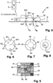
- Fig. 10 shows an exemplary temperature development plot of the enhanced thermistor arrangements described in Fig. 9 above.
- Curve 10A is exemplary of a temperature calculated on the basis of temperature measurement values from three enhanced thermistor arrangements of which the inner thermistors are in good contact with the patient's skin.
- Curve 10B is exemplary of a temperature calculated on the basis of temperature measurement values from a fourth enhanced thermistor arrangement of which the inner thermistors are in poor contact with the patient's skin. Owing to the persistent significant difference in the values, the evaluation unit would disregard the values provided by the fourth enhanced thermistor arrangement from the temperature calculation algorithm.
- the final estimated core body temperature depends to a large extent on the geometry and thermal conductivity of the sensor. Experimental results have shown that even during sub-optimal conditions, the enhanced sensor performs very well. When applied to a reference body that is gradually heated, the temperature sensed using data provided by an enhanced single heat-flow sensor is a much closer match than the temperature sensed using data provided by the conventional single heat-flow sensor. Similarly, the temperature sensed by an enhanced dual heat-flow sensor according to the invention has been observed to be more precise than a comparable conventional dual sensor, which - although considered to be quite accurate - can report sensed temperatures that are off by about 0.4°C. This is considered to be a significant discrepancy regarding core body temperature, particularly when it is necessary to identify a tendency towards hypothermia or hyperthermia so that preventive measures can be taken to avoid a critical situation.
- the improvement in accuracy of the enhanced heat-flow sensor is because it considers lateral heat flow also, and is therefore significantly less sensitive to variations in ambient temperature.
- the improvement in accuracy has been observed for a reference body with a constant temperature at 37.5°C and a variation in the ambient or outside temperature from 0°C to 30° C.
- the body temperature as measured by the enhanced heat-flow sensor remains essentially constant for all values of ambient temperature, whereas a comparable conventional heat-flow sensor exhibits relatively poor performance particularly at the lower temperatures,
- the enhanced heat-flow sensor performs significantly better than its conventional counterpart which does not.
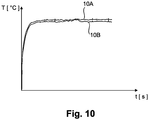
- Fig. 11 shows a further example of the passive heat-flow sensor, realized as a single heat-flow sensor and comprising vertical thermistor pairs S1, S2, giving a configuration of enhanced thermistor arrangements, each comprising a vertical thermistor pair S1, S2 and a lateral thermistor corresponding to the lower thermistor S1 of a neighboring vertical thermistor pair.
- the temperature measurement values of the thermistors S1, S2 are examined to identify the pair V max with the maximum vertical heat flow. Of this vertical thermistor pair V max , the inner thermistor S1 and outer thermistor S2 will supply the values for T1 and T2 of equation (2) above.
- a value of T3 can be determined by obtaining the mean temperature of a neighboring vertical pair, for example the vertical pair V left on the left of the "maximum vertical flux" pair V max or the vertical pair V right on the right, etc. by adding the temperature measurement values of the thermistors S1, S2 and halving the result. The most likely result can be chosen as the value for T3 in equation (2) above.
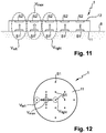
- Fig. 12 shows a plan view of the single heat-flow sensor of Fig. 11 , showing its contact face 11.
- the positions of the inner thermistors S1 are shown.
- the location of the thermistor pair V max with the maximum vertical heat flow is indicated by the dotted line encircling the corresponding inner thermistor.
- the diagram shows that this thermistor pair V max has four possible "neighbors" (two such pairs V left , V right were described in Fig. 11 ), any of which can be used to determine a value of T3 as described above.
- the advantage of being able to choose between multiple neighboring thermistors is that any erroneous temperature measurement values (arising from sub-optimal contact to the patient's skin, for example) can be identified and disregarded, as explained in Fig. 9 above.
- any suitable sensor shape may be used.
- different numbers of vertical and lateral thermistors can be incorporated in various examples of the enhanced heat-flow sensor.
- calculation of core temperature can be performed on the sensor or can be performed remotely. Results can be displayed locally (on a screen) or remotely on a smart watch, mobile phone or the display of any other suitable device.
- the principle of the invention can be used in an active sensor realization, for example by controlling a heating element to bring the sensor to a zero heat-flux state.
Landscapes
- Physics & Mathematics (AREA)
- Health & Medical Sciences (AREA)
- Life Sciences & Earth Sciences (AREA)
- General Physics & Mathematics (AREA)
- Heart & Thoracic Surgery (AREA)
- Surgery (AREA)
- Engineering & Computer Science (AREA)
- Biomedical Technology (AREA)
- Biophysics (AREA)
- Medical Informatics (AREA)
- Molecular Biology (AREA)
- Pathology (AREA)
- Animal Behavior & Ethology (AREA)
- General Health & Medical Sciences (AREA)
- Public Health (AREA)
- Veterinary Medicine (AREA)
- Measuring And Recording Apparatus For Diagnosis (AREA)
- Measuring Temperature Or Quantity Of Heat (AREA)
Claims (14)
- Passiver dualer Wärmestromsensor (1), umfassend eine Kontaktfläche (11) zur Platzierung auf einem Subjekt (8) während einer Temperaturüberwachungsmaßnahme;- eine untere Schicht;- eine obere Schicht;- eine vertikale Thermistoranordnung (SV1, SV2), umfassend einen inneren Thermistor (SV1), der an der inneren Fläche der unteren Schicht des Sensors (1) angeordnet ist, und einen oberen Sensor (SV2), der an einer oberen Fläche der oberen Schicht des Sensors(1) angeordnet ist; und- eine Vielzahl kombinierter Thermistoranordnungen, wobei eine kombinierte Thermistoranordnung Folgendes umfasst:- einen inneren Thermistor (S1), der an einer inneren Fläche der unteren Schicht des Sensors (1) angeordnet ist;- einen oberen Thermistor (S2), der an der oberen Fläche der unteren Schicht des Sensors (1) angeordnet ist und relativ zu dem inneren Thermistor (S1) angeordnet ist, um einen vertikalen Wärmestrom ausgehend von dem Subjekt (8) zu messen; und- einen seitlichen Thermistor (S3), der in Übereinstimmung mit dem inneren Thermistor (S1) angeordnet ist, um einen horizontalen Wärmestrom entlang der Kontaktfläche (11) zu messen.
- Passiver dualer Wärmestromsensor nach Anspruch 1, umfassend mindestens vier kombinierte Thermistoranordnungen.
- Passiver dualer Wärmestromsensor nach Anspruch 1 oder Anspruch 2, umfassend eine Vielzahl vertikaler Thermistorpaare (S1, S2), wobei ein vertikales Thermistorpaar einen inneren Thermistor (S1) und einen oberen Thermistor (S2) umfasst.
- Passiver dualer Wärmestromsensor nach einem der vorstehenden Ansprüche, wobei die äußere Oberfläche (12) des Sensors (1) freiliegt.
- Passiver dualer Wärmestromsensor nach Anspruch 1, wobei die vertikale Thermistoranordnung (SV1, SV2) zentral in dem Wärmestromsensor (1) positioniert ist.
- Verfahren zum Messen der Temperatur eines Subjekts (8) unter Verwendung eines passiven Wärmestromsensors (1) nach einem der Ansprüche 1 bis 5, wobei das Verfahren die folgenden Schritte umfasst:- Platzieren der Kontaktfläche (11) des passiven Wärmestromsensors (1) an dem Subjekt (8) während einer Temperaturüberwachungsmaßnahme;- Empfangen von Temperaturmesswerten (T1, T2, T3, TV1, TV2), die von den Thermistoren (S1, S2, S3, SV1, SV2) des passiven dualen Wärmestromsensors (1) gesammelt wurden; und- Berechnen der Temperatur des Subjekts (8) auf der Basis der empfangenen Temperaturmesswerte (T1, T2, T3, TV1, TV2).
- Verfahren nach Anspruch 6, das die folgenden Schritte umfasst:- Vergleichen der Temperaturmesswerte (T1, T2, T3) der kombinierten Thermistoranordnungen des passiven dualen Wärmestromsensors (1), um mit einem maximalen vertikalen Wärmestrom assoziierte Thermistoren (Vmax) zu identifizieren;- Identifizieren der benachbarten kombinierten Thermistoren (Vlinks, Vrechts); und- Berechnen der Temperatur des Subjekts (8) auf der Basis der Temperaturmesswerte (T1, T2, T3) dieser Thermistoren.
- Verfahren nach Anspruch 6 oder Anspruch 7, umfassend den Schritt des Mittelns eines oder mehrere Temperaturmesswerte vor dem Berechnen der Temperatur des Subjekts (8).
- Verfahren nach einem der Ansprüche 6 bis 8, das die folgenden Schritte umfasst:- Vergleichen von Temperaturmesswerten (T1, T2, T3) der kombinierten Thermistoranordnungen (S1, S2, S3) des passiven dualen Wärmestromsensors (1);- Identifizieren einer kombinierten Thermistoranordnung (S1, S2, S3), die unzuverlässige Temperaturmesswerte (T1, T2, T3) bereitstellt; und- Verwerfen von dieser kombinierten Thermistoranordnung (S1, S2, S3) gesammelter Temperaturmesswerte (T1, T2, T3).
- Temperaturfühlanordnung (10) zum Überwachen der Temperatur eines Subjekts (8), die Folgendes umfasst:- einen passiven dualen Wärmestromsensor (1) nach einem der Ansprüche 1 bis 6; und- eine Auswertungseinheit (2), die angeordnet ist, um Temperaturmesswerte (T1, T2, T3, TV1, TV2) von den Thermistoren (S1, S2, S3, SV1, SV2) des passiven Wärmestromsensors (1) zu empfangen und die Temperatur des Subjekts (8) auf der Basis der empfangenen Temperaturmesswerte (T1, T2, T3, TV1, TV2) zu berechnen.
- Temperaturfühlanordnung nach Anspruch 10, wobei der passive Wärmestromsensor (1) eine drahtlose Schnittstelle (5) zum Übermitteln von Temperaturmesswerten (T1, T2, T3, TV1, TV2) an die Auswertungseinheit (2) umfasst.
- Temperaturfühlanordnung nach Anspruch 10 oder Anspruch 11, wobei der passive Wärmestromsensor (1) als tragbares Gerät ausgeführt ist.
- Temperaturfühlanordnung nach einem der Ansprüche 10 bis 12, wobei die Auswertungseinheit (2) als portables Gerät ausgeführt ist.
- Temperaturfühlanordnung nach einem der Ansprüche 10 bis 13, intergiert in ein Patientenunterstützungsgerät.
Applications Claiming Priority (2)
| Application Number | Priority Date | Filing Date | Title |
|---|---|---|---|
| EP15201450 | 2015-12-21 | ||
| PCT/EP2016/082200 WO2017108964A1 (en) | 2015-12-21 | 2016-12-21 | Heat-flow sensor |
Publications (2)
| Publication Number | Publication Date |
|---|---|
| EP3394580A1 EP3394580A1 (de) | 2018-10-31 |
| EP3394580B1 true EP3394580B1 (de) | 2019-11-27 |
Family
ID=55027381
Family Applications (1)
| Application Number | Title | Priority Date | Filing Date |
|---|---|---|---|
| EP16826324.2A Active EP3394580B1 (de) | 2015-12-21 | 2016-12-21 | Wärmeflusssensor |
Country Status (7)
| Country | Link |
|---|---|
| US (1) | US10866147B2 (de) |
| EP (1) | EP3394580B1 (de) |
| JP (1) | JP6666446B2 (de) |
| CN (1) | CN108431564B (de) |
| BR (1) | BR112018012423A2 (de) |
| RU (1) | RU2018126837A (de) |
| WO (1) | WO2017108964A1 (de) |
Families Citing this family (19)
| Publication number | Priority date | Publication date | Assignee | Title |
|---|---|---|---|---|
| CN113367671A (zh) | 2015-08-31 | 2021-09-10 | 梅西莫股份有限公司 | 无线式病人监护系统和方法 |
| WO2018229581A1 (en) | 2017-06-11 | 2018-12-20 | Kenzen Ag | Chip-based multi-channel electrochemical transducer and method of use thereof |
| CN111741709A (zh) * | 2017-12-28 | 2020-10-02 | 罗伯特·博世有限公司 | 具有两个teg的主体核心温度传感器 |
| JP7073940B2 (ja) * | 2018-06-27 | 2022-05-24 | 日本電信電話株式会社 | 生体内温度測定装置および生体内温度測定方法 |
| US11534568B2 (en) | 2018-06-28 | 2022-12-27 | Koninklijke Philips N.V. | Pressure support system and method of providing pressure support therapy to a patient |
| JP7149575B2 (ja) * | 2018-08-10 | 2022-10-07 | 株式会社Msd | バイタル情報収集システム、及びプログラム |
| EP3666179A1 (de) * | 2018-12-11 | 2020-06-17 | Koninklijke Philips N.V. | Kernkörpertemperatursensorsystem auf basis von flussmessung |
| CN109632144B (zh) * | 2019-01-22 | 2023-08-22 | 浙江大学 | 一种用于确定生物核心温度的测量探头 |
| CN109883571B (zh) * | 2019-01-22 | 2021-05-04 | 浙江想能睡眠科技股份有限公司 | 一种用于智能床垫温控检测的温度采集装置及其采集方法 |
| EP3699570A1 (de) * | 2019-02-19 | 2020-08-26 | Nederlandse Organisatie voor toegepast- natuurwetenschappelijk onderzoek TNO | Kernkörpertemperatursensor und verfahren zur herstellung davon |
| KR20210153684A (ko) | 2019-04-17 | 2021-12-17 | 마시모 코오퍼레이션 | 환자 모니터링 시스템, 디바이스 및 방법 |
| USD985498S1 (en) | 2019-08-16 | 2023-05-09 | Masimo Corporation | Connector |
| USD917704S1 (en) | 2019-08-16 | 2021-04-27 | Masimo Corporation | Patient monitor |
| USD919094S1 (en) | 2019-08-16 | 2021-05-11 | Masimo Corporation | Blood pressure device |
| USD927699S1 (en) | 2019-10-18 | 2021-08-10 | Masimo Corporation | Electrode pad |
| CN111141420A (zh) * | 2020-02-04 | 2020-05-12 | 上海申矽凌微电子科技有限公司 | 基于热流法的物体深部温度测量方法及装置 |
| USD933232S1 (en) | 2020-05-11 | 2021-10-12 | Masimo Corporation | Blood pressure monitor |
| USD979516S1 (en) | 2020-05-11 | 2023-02-28 | Masimo Corporation | Connector |
| WO2021234986A1 (ja) * | 2020-05-19 | 2021-11-25 | 拓則 島崎 | 体調変化検知装置、及び体調変化管理システム |
Citations (1)
| Publication number | Priority date | Publication date | Assignee | Title |
|---|---|---|---|---|
| US20120128024A1 (en) * | 2010-11-24 | 2012-05-24 | Citizen Holdings Co., Ltd. | Temperature measuring device |
Family Cites Families (21)
| Publication number | Priority date | Publication date | Assignee | Title |
|---|---|---|---|---|
| JPS6358223A (ja) * | 1986-08-29 | 1988-03-14 | Tatsuo Togawa | 体温計測装置 |
| US5711604A (en) | 1993-12-14 | 1998-01-27 | Seiko Instruments Inc. | Method for measuring the coefficient of heat conductivity of a sample |
| JP3103963B2 (ja) * | 1993-12-14 | 2000-10-30 | セイコーインスツルメンツ株式会社 | 熱伝導率の測定方法 |
| FI96066C (fi) * | 1994-03-24 | 1996-04-25 | Polar Electro Oy | Menetelmä ja laite rakenteen sisälämpötilan ja sisäisen lämmönjohtavuuskertoimen määrittämiseksi |
| JPH08304144A (ja) * | 1995-05-12 | 1996-11-22 | Idoutai Tsushin Sentan Gijutsu Kenkyusho:Kk | 液面計 |
| US6220750B1 (en) * | 1999-03-29 | 2001-04-24 | Yoram Palti | Non-invasive temperature measurement method and apparatus |
| US6735379B2 (en) * | 2000-06-28 | 2004-05-11 | Fisher & Paykel Healthcare Limited | Energy sensor |
| JP4157914B2 (ja) * | 2002-03-20 | 2008-10-01 | 坂野 數仁 | 温度測定装置及び温度測定方法 |
| JP4600170B2 (ja) * | 2004-09-15 | 2010-12-15 | セイコーエプソン株式会社 | 体温計、および体温計を有する電子機器 |
| DE102005004933B3 (de) * | 2005-02-03 | 2006-08-31 | Dräger Safety AG & Co. KGaA | Vorrichtung zur Messung der Körpertemperatur eines Lebewesens |
| JP2006280762A (ja) * | 2005-04-04 | 2006-10-19 | Anet Corporation | ライフコンディションレコーダー装置および身体情報処理システム |
| JP2007315917A (ja) * | 2006-05-25 | 2007-12-06 | Terumo Corp | 深部温度測定装置及び外部通信装置 |
| WO2008068665A1 (en) | 2006-12-06 | 2008-06-12 | Koninklijke Philips Electronics, N.V. | Device for measuring core temperature |
| DE102008026642B4 (de) * | 2008-06-03 | 2010-06-10 | Dräger Medical AG & Co. KG | Doppeltemperatursensor mit einem Aufnahmeelement |
| RU2521734C2 (ru) | 2009-03-13 | 2014-07-10 | Конинклейке Филипс Электроникс Н.В. | Датчик измерения температуры нулевого теплового потока |
| JP5654567B2 (ja) | 2009-04-06 | 2015-01-14 | コーニンクレッカ フィリップス エヌ ヴェ | 体温測定のための温度センサ |
| ES2710276T3 (es) | 2009-07-27 | 2019-04-24 | Csem Ct Suisse Delectronique Microtechnique Sa Rech Developpement | Sensor y método para determinar la temperatura corporal central |
| JP5648283B2 (ja) | 2009-12-24 | 2015-01-07 | セイコーエプソン株式会社 | 電子体温計及び体温測定方法 |
| JP5578029B2 (ja) | 2010-10-29 | 2014-08-27 | セイコーエプソン株式会社 | 温度測定装置および温度測定方法 |
| US8657758B2 (en) * | 2010-12-02 | 2014-02-25 | Welch Allyn, Inc. | Devices and methods for temperature determination |
| WO2013121762A1 (ja) | 2012-02-14 | 2013-08-22 | テルモ株式会社 | 体温計及び体温測定システム |
-
2016
- 2016-12-21 JP JP2018532172A patent/JP6666446B2/ja active Active
- 2016-12-21 BR BR112018012423A patent/BR112018012423A2/pt not_active Application Discontinuation
- 2016-12-21 CN CN201680075191.5A patent/CN108431564B/zh active Active
- 2016-12-21 RU RU2018126837A patent/RU2018126837A/ru not_active Application Discontinuation
- 2016-12-21 EP EP16826324.2A patent/EP3394580B1/de active Active
- 2016-12-21 WO PCT/EP2016/082200 patent/WO2017108964A1/en active Application Filing
- 2016-12-21 US US15/781,867 patent/US10866147B2/en active Active
Patent Citations (1)
| Publication number | Priority date | Publication date | Assignee | Title |
|---|---|---|---|---|
| US20120128024A1 (en) * | 2010-11-24 | 2012-05-24 | Citizen Holdings Co., Ltd. | Temperature measuring device |
Also Published As
| Publication number | Publication date |
|---|---|
| CN108431564B (zh) | 2021-04-23 |
| US20180364109A1 (en) | 2018-12-20 |
| JP6666446B2 (ja) | 2020-03-13 |
| WO2017108964A1 (en) | 2017-06-29 |
| CN108431564A (zh) | 2018-08-21 |
| US10866147B2 (en) | 2020-12-15 |
| BR112018012423A2 (pt) | 2018-12-18 |
| RU2018126837A (ru) | 2020-01-23 |
| JP2019501389A (ja) | 2019-01-17 |
| EP3394580A1 (de) | 2018-10-31 |
Similar Documents
| Publication | Publication Date | Title |
|---|---|---|
| EP3394580B1 (de) | Wärmeflusssensor | |
| US11109764B2 (en) | Single heat flux sensor arrangement | |
| US20210307618A1 (en) | Biological data measurement device | |
| US10827931B2 (en) | Patch for temperature determination | |
| US20200060869A1 (en) | Core body temperature measurement | |
| CN108431566B (zh) | 预测热流传感器的稳定温度的方法 | |
| AU2018223205B2 (en) | Temperature sensor | |
| EP3156774A1 (de) | System und verfahren zur kernkörpertemperaturmessung | |
| US20180008149A1 (en) | Systems and Methods of Body Temperature Measurement | |
| WO2017140525A1 (en) | Heat-flow sensor and sensor arrangement | |
| US20220000370A1 (en) | Core body temperature sensor system based on flux measurement | |
| CN111741710B (zh) | 核心温度检测系统和方法 | |
| WO2014088886A1 (en) | Csf shunt flow evaluation apparatus and method using a conformable expanded dynamic range thermosensor | |
| KR102454112B1 (ko) | 온도센서가 장착된 앤지오카테터 | |
| Kramme et al. | Temperature Monitoring |
Legal Events
| Date | Code | Title | Description |
|---|---|---|---|
| STAA | Information on the status of an ep patent application or granted ep patent |
Free format text: STATUS: UNKNOWN |
|
| STAA | Information on the status of an ep patent application or granted ep patent |
Free format text: STATUS: THE INTERNATIONAL PUBLICATION HAS BEEN MADE |
|
| PUAI | Public reference made under article 153(3) epc to a published international application that has entered the european phase |
Free format text: ORIGINAL CODE: 0009012 |
|
| STAA | Information on the status of an ep patent application or granted ep patent |
Free format text: STATUS: REQUEST FOR EXAMINATION WAS MADE |
|
| 17P | Request for examination filed |
Effective date: 20180723 |
|
| AK | Designated contracting states |
Kind code of ref document: A1 Designated state(s): AL AT BE BG CH CY CZ DE DK EE ES FI FR GB GR HR HU IE IS IT LI LT LU LV MC MK MT NL NO PL PT RO RS SE SI SK SM TR |
|
| AX | Request for extension of the european patent |
Extension state: BA ME |
|
| STAA | Information on the status of an ep patent application or granted ep patent |
Free format text: STATUS: EXAMINATION IS IN PROGRESS |
|
| 17Q | First examination report despatched |
Effective date: 20190103 |
|
| DAV | Request for validation of the european patent (deleted) | ||
| DAX | Request for extension of the european patent (deleted) | ||
| RIC1 | Information provided on ipc code assigned before grant |
Ipc: G01K 7/42 20060101ALI20190430BHEP Ipc: A61B 5/00 20060101ALI20190430BHEP Ipc: A61B 5/01 20060101ALI20190430BHEP Ipc: G01K 13/00 20060101ALI20190430BHEP Ipc: G01K 1/16 20060101AFI20190430BHEP |
|
| GRAP | Despatch of communication of intention to grant a patent |
Free format text: ORIGINAL CODE: EPIDOSNIGR1 |
|
| STAA | Information on the status of an ep patent application or granted ep patent |
Free format text: STATUS: GRANT OF PATENT IS INTENDED |
|
| INTG | Intention to grant announced |
Effective date: 20190621 |
|
| GRAS | Grant fee paid |
Free format text: ORIGINAL CODE: EPIDOSNIGR3 |
|
| GRAA | (expected) grant |
Free format text: ORIGINAL CODE: 0009210 |
|
| STAA | Information on the status of an ep patent application or granted ep patent |
Free format text: STATUS: THE PATENT HAS BEEN GRANTED |
|
| AK | Designated contracting states |
Kind code of ref document: B1 Designated state(s): AL AT BE BG CH CY CZ DE DK EE ES FI FR GB GR HR HU IE IS IT LI LT LU LV MC MK MT NL NO PL PT RO RS SE SI SK SM TR |
|
| REG | Reference to a national code |
Ref country code: GB Ref legal event code: FG4D |
|
| REG | Reference to a national code |
Ref country code: CH Ref legal event code: EP |
|
| REG | Reference to a national code |
Ref country code: DE Ref legal event code: R096 Ref document number: 602016025271 Country of ref document: DE |
|
| REG | Reference to a national code |
Ref country code: AT Ref legal event code: REF Ref document number: 1207219 Country of ref document: AT Kind code of ref document: T Effective date: 20191215 |
|
| REG | Reference to a national code |
Ref country code: IE Ref legal event code: FG4D |
|
| RAP2 | Party data changed (patent owner data changed or rights of a patent transferred) |
Owner name: KONINKLIJKE PHILIPS N.V. |
|
| REG | Reference to a national code |
Ref country code: NL Ref legal event code: MP Effective date: 20191127 |
|
| REG | Reference to a national code |
Ref country code: LT Ref legal event code: MG4D |
|
| PG25 | Lapsed in a contracting state [announced via postgrant information from national office to epo] |
Ref country code: FI Free format text: LAPSE BECAUSE OF FAILURE TO SUBMIT A TRANSLATION OF THE DESCRIPTION OR TO PAY THE FEE WITHIN THE PRESCRIBED TIME-LIMIT Effective date: 20191127 Ref country code: BG Free format text: LAPSE BECAUSE OF FAILURE TO SUBMIT A TRANSLATION OF THE DESCRIPTION OR TO PAY THE FEE WITHIN THE PRESCRIBED TIME-LIMIT Effective date: 20200227 Ref country code: LT Free format text: LAPSE BECAUSE OF FAILURE TO SUBMIT A TRANSLATION OF THE DESCRIPTION OR TO PAY THE FEE WITHIN THE PRESCRIBED TIME-LIMIT Effective date: 20191127 Ref country code: GR Free format text: LAPSE BECAUSE OF FAILURE TO SUBMIT A TRANSLATION OF THE DESCRIPTION OR TO PAY THE FEE WITHIN THE PRESCRIBED TIME-LIMIT Effective date: 20200228 Ref country code: NO Free format text: LAPSE BECAUSE OF FAILURE TO SUBMIT A TRANSLATION OF THE DESCRIPTION OR TO PAY THE FEE WITHIN THE PRESCRIBED TIME-LIMIT Effective date: 20200227 Ref country code: SE Free format text: LAPSE BECAUSE OF FAILURE TO SUBMIT A TRANSLATION OF THE DESCRIPTION OR TO PAY THE FEE WITHIN THE PRESCRIBED TIME-LIMIT Effective date: 20191127 Ref country code: LV Free format text: LAPSE BECAUSE OF FAILURE TO SUBMIT A TRANSLATION OF THE DESCRIPTION OR TO PAY THE FEE WITHIN THE PRESCRIBED TIME-LIMIT Effective date: 20191127 Ref country code: NL Free format text: LAPSE BECAUSE OF FAILURE TO SUBMIT A TRANSLATION OF THE DESCRIPTION OR TO PAY THE FEE WITHIN THE PRESCRIBED TIME-LIMIT Effective date: 20191127 |
|
| PG25 | Lapsed in a contracting state [announced via postgrant information from national office to epo] |
Ref country code: HR Free format text: LAPSE BECAUSE OF FAILURE TO SUBMIT A TRANSLATION OF THE DESCRIPTION OR TO PAY THE FEE WITHIN THE PRESCRIBED TIME-LIMIT Effective date: 20191127 Ref country code: RS Free format text: LAPSE BECAUSE OF FAILURE TO SUBMIT A TRANSLATION OF THE DESCRIPTION OR TO PAY THE FEE WITHIN THE PRESCRIBED TIME-LIMIT Effective date: 20191127 Ref country code: IS Free format text: LAPSE BECAUSE OF FAILURE TO SUBMIT A TRANSLATION OF THE DESCRIPTION OR TO PAY THE FEE WITHIN THE PRESCRIBED TIME-LIMIT Effective date: 20200327 |
|
| PG25 | Lapsed in a contracting state [announced via postgrant information from national office to epo] |
Ref country code: AL Free format text: LAPSE BECAUSE OF FAILURE TO SUBMIT A TRANSLATION OF THE DESCRIPTION OR TO PAY THE FEE WITHIN THE PRESCRIBED TIME-LIMIT Effective date: 20191127 |
|
| PG25 | Lapsed in a contracting state [announced via postgrant information from national office to epo] |
Ref country code: EE Free format text: LAPSE BECAUSE OF FAILURE TO SUBMIT A TRANSLATION OF THE DESCRIPTION OR TO PAY THE FEE WITHIN THE PRESCRIBED TIME-LIMIT Effective date: 20191127 Ref country code: PT Free format text: LAPSE BECAUSE OF FAILURE TO SUBMIT A TRANSLATION OF THE DESCRIPTION OR TO PAY THE FEE WITHIN THE PRESCRIBED TIME-LIMIT Effective date: 20200419 Ref country code: DK Free format text: LAPSE BECAUSE OF FAILURE TO SUBMIT A TRANSLATION OF THE DESCRIPTION OR TO PAY THE FEE WITHIN THE PRESCRIBED TIME-LIMIT Effective date: 20191127 Ref country code: RO Free format text: LAPSE BECAUSE OF FAILURE TO SUBMIT A TRANSLATION OF THE DESCRIPTION OR TO PAY THE FEE WITHIN THE PRESCRIBED TIME-LIMIT Effective date: 20191127 Ref country code: CZ Free format text: LAPSE BECAUSE OF FAILURE TO SUBMIT A TRANSLATION OF THE DESCRIPTION OR TO PAY THE FEE WITHIN THE PRESCRIBED TIME-LIMIT Effective date: 20191127 Ref country code: ES Free format text: LAPSE BECAUSE OF FAILURE TO SUBMIT A TRANSLATION OF THE DESCRIPTION OR TO PAY THE FEE WITHIN THE PRESCRIBED TIME-LIMIT Effective date: 20191127 |
|
| REG | Reference to a national code |
Ref country code: CH Ref legal event code: PL |
|
| REG | Reference to a national code |
Ref country code: BE Ref legal event code: MM Effective date: 20191231 |
|
| REG | Reference to a national code |
Ref country code: DE Ref legal event code: R097 Ref document number: 602016025271 Country of ref document: DE |
|
| PG25 | Lapsed in a contracting state [announced via postgrant information from national office to epo] |
Ref country code: MC Free format text: LAPSE BECAUSE OF FAILURE TO SUBMIT A TRANSLATION OF THE DESCRIPTION OR TO PAY THE FEE WITHIN THE PRESCRIBED TIME-LIMIT Effective date: 20191127 Ref country code: SM Free format text: LAPSE BECAUSE OF FAILURE TO SUBMIT A TRANSLATION OF THE DESCRIPTION OR TO PAY THE FEE WITHIN THE PRESCRIBED TIME-LIMIT Effective date: 20191127 Ref country code: SK Free format text: LAPSE BECAUSE OF FAILURE TO SUBMIT A TRANSLATION OF THE DESCRIPTION OR TO PAY THE FEE WITHIN THE PRESCRIBED TIME-LIMIT Effective date: 20191127 |
|
| REG | Reference to a national code |
Ref country code: AT Ref legal event code: MK05 Ref document number: 1207219 Country of ref document: AT Kind code of ref document: T Effective date: 20191127 |
|
| PLBE | No opposition filed within time limit |
Free format text: ORIGINAL CODE: 0009261 |
|
| STAA | Information on the status of an ep patent application or granted ep patent |
Free format text: STATUS: NO OPPOSITION FILED WITHIN TIME LIMIT |
|
| PG25 | Lapsed in a contracting state [announced via postgrant information from national office to epo] |
Ref country code: IE Free format text: LAPSE BECAUSE OF NON-PAYMENT OF DUE FEES Effective date: 20191221 Ref country code: LU Free format text: LAPSE BECAUSE OF NON-PAYMENT OF DUE FEES Effective date: 20191221 |
|
| 26N | No opposition filed |
Effective date: 20200828 |
|
| PG25 | Lapsed in a contracting state [announced via postgrant information from national office to epo] |
Ref country code: LI Free format text: LAPSE BECAUSE OF NON-PAYMENT OF DUE FEES Effective date: 20191231 Ref country code: AT Free format text: LAPSE BECAUSE OF FAILURE TO SUBMIT A TRANSLATION OF THE DESCRIPTION OR TO PAY THE FEE WITHIN THE PRESCRIBED TIME-LIMIT Effective date: 20191127 Ref country code: PL Free format text: LAPSE BECAUSE OF FAILURE TO SUBMIT A TRANSLATION OF THE DESCRIPTION OR TO PAY THE FEE WITHIN THE PRESCRIBED TIME-LIMIT Effective date: 20191127 Ref country code: CH Free format text: LAPSE BECAUSE OF NON-PAYMENT OF DUE FEES Effective date: 20191231 Ref country code: SI Free format text: LAPSE BECAUSE OF FAILURE TO SUBMIT A TRANSLATION OF THE DESCRIPTION OR TO PAY THE FEE WITHIN THE PRESCRIBED TIME-LIMIT Effective date: 20191127 Ref country code: BE Free format text: LAPSE BECAUSE OF NON-PAYMENT OF DUE FEES Effective date: 20191231 |
|
| PG25 | Lapsed in a contracting state [announced via postgrant information from national office to epo] |
Ref country code: IT Free format text: LAPSE BECAUSE OF FAILURE TO SUBMIT A TRANSLATION OF THE DESCRIPTION OR TO PAY THE FEE WITHIN THE PRESCRIBED TIME-LIMIT Effective date: 20191127 |
|
| PG25 | Lapsed in a contracting state [announced via postgrant information from national office to epo] |
Ref country code: CY Free format text: LAPSE BECAUSE OF FAILURE TO SUBMIT A TRANSLATION OF THE DESCRIPTION OR TO PAY THE FEE WITHIN THE PRESCRIBED TIME-LIMIT Effective date: 20191127 |
|
| PG25 | Lapsed in a contracting state [announced via postgrant information from national office to epo] |
Ref country code: MT Free format text: LAPSE BECAUSE OF FAILURE TO SUBMIT A TRANSLATION OF THE DESCRIPTION OR TO PAY THE FEE WITHIN THE PRESCRIBED TIME-LIMIT Effective date: 20191127 Ref country code: HU Free format text: LAPSE BECAUSE OF FAILURE TO SUBMIT A TRANSLATION OF THE DESCRIPTION OR TO PAY THE FEE WITHIN THE PRESCRIBED TIME-LIMIT; INVALID AB INITIO Effective date: 20161221 |
|
| GBPC | Gb: european patent ceased through non-payment of renewal fee |
Effective date: 20201221 |
|
| PG25 | Lapsed in a contracting state [announced via postgrant information from national office to epo] |
Ref country code: GB Free format text: LAPSE BECAUSE OF NON-PAYMENT OF DUE FEES Effective date: 20201221 |
|
| PG25 | Lapsed in a contracting state [announced via postgrant information from national office to epo] |
Ref country code: TR Free format text: LAPSE BECAUSE OF FAILURE TO SUBMIT A TRANSLATION OF THE DESCRIPTION OR TO PAY THE FEE WITHIN THE PRESCRIBED TIME-LIMIT Effective date: 20191127 |
|
| PG25 | Lapsed in a contracting state [announced via postgrant information from national office to epo] |
Ref country code: MK Free format text: LAPSE BECAUSE OF FAILURE TO SUBMIT A TRANSLATION OF THE DESCRIPTION OR TO PAY THE FEE WITHIN THE PRESCRIBED TIME-LIMIT Effective date: 20191127 |
|
| PGFP | Annual fee paid to national office [announced via postgrant information from national office to epo] |
Ref country code: FR Payment date: 20231226 Year of fee payment: 8 |
|
| PGFP | Annual fee paid to national office [announced via postgrant information from national office to epo] |
Ref country code: DE Payment date: 20231227 Year of fee payment: 8 |