EP3394510B1 - Vaporization device - Google Patents
Vaporization device Download PDFInfo
- Publication number
- EP3394510B1 EP3394510B1 EP16878602.8A EP16878602A EP3394510B1 EP 3394510 B1 EP3394510 B1 EP 3394510B1 EP 16878602 A EP16878602 A EP 16878602A EP 3394510 B1 EP3394510 B1 EP 3394510B1
- Authority
- EP
- European Patent Office
- Prior art keywords
- fluid
- vaporizer
- bubble
- vaporization
- bubble pump
- Prior art date
- Legal status (The legal status is an assumption and is not a legal conclusion. Google has not performed a legal analysis and makes no representation as to the accuracy of the status listed.)
- Active
Links
- 230000008016 vaporization Effects 0.000 title claims description 64
- 238000009834 vaporization Methods 0.000 title claims description 60
- 239000012530 fluid Substances 0.000 claims description 164
- 239000000758 substrate Substances 0.000 claims description 29
- 238000012163 sequencing technique Methods 0.000 claims description 4
- 238000004891 communication Methods 0.000 claims description 3
- 239000006200 vaporizer Substances 0.000 description 73
- 230000032258 transport Effects 0.000 description 9
- 239000000463 material Substances 0.000 description 6
- XUIMIQQOPSSXEZ-UHFFFAOYSA-N Silicon Chemical compound [Si] XUIMIQQOPSSXEZ-UHFFFAOYSA-N 0.000 description 4
- 239000007788 liquid Substances 0.000 description 4
- 229910052710 silicon Inorganic materials 0.000 description 4
- 239000010703 silicon Substances 0.000 description 4
- 239000004642 Polyimide Substances 0.000 description 2
- 238000009835 boiling Methods 0.000 description 2
- 238000010304 firing Methods 0.000 description 2
- 238000010438 heat treatment Methods 0.000 description 2
- 238000004519 manufacturing process Methods 0.000 description 2
- 239000000203 mixture Substances 0.000 description 2
- 238000013021 overheating Methods 0.000 description 2
- 229920001721 polyimide Polymers 0.000 description 2
- 238000005086 pumping Methods 0.000 description 2
- 239000004065 semiconductor Substances 0.000 description 2
- 238000004544 sputter deposition Methods 0.000 description 2
- 239000010409 thin film Substances 0.000 description 2
- 229910004490 TaAl Inorganic materials 0.000 description 1
- 238000006243 chemical reaction Methods 0.000 description 1
- 238000000034 method Methods 0.000 description 1
- 239000000126 substance Substances 0.000 description 1
- 238000002560 therapeutic procedure Methods 0.000 description 1
Images


Classifications
-
- A—HUMAN NECESSITIES
- A61—MEDICAL OR VETERINARY SCIENCE; HYGIENE
- A61M—DEVICES FOR INTRODUCING MEDIA INTO, OR ONTO, THE BODY; DEVICES FOR TRANSDUCING BODY MEDIA OR FOR TAKING MEDIA FROM THE BODY; DEVICES FOR PRODUCING OR ENDING SLEEP OR STUPOR
- A61M11/00—Sprayers or atomisers specially adapted for therapeutic purposes
- A61M11/04—Sprayers or atomisers specially adapted for therapeutic purposes operated by the vapour pressure of the liquid to be sprayed or atomised
- A61M11/041—Sprayers or atomisers specially adapted for therapeutic purposes operated by the vapour pressure of the liquid to be sprayed or atomised using heaters
- A61M11/042—Sprayers or atomisers specially adapted for therapeutic purposes operated by the vapour pressure of the liquid to be sprayed or atomised using heaters electrical
- A61M11/044—Sprayers or atomisers specially adapted for therapeutic purposes operated by the vapour pressure of the liquid to be sprayed or atomised using heaters electrical with electrodes immersed in the liquid
-
- A—HUMAN NECESSITIES
- A61—MEDICAL OR VETERINARY SCIENCE; HYGIENE
- A61M—DEVICES FOR INTRODUCING MEDIA INTO, OR ONTO, THE BODY; DEVICES FOR TRANSDUCING BODY MEDIA OR FOR TAKING MEDIA FROM THE BODY; DEVICES FOR PRODUCING OR ENDING SLEEP OR STUPOR
- A61M15/00—Inhalators
- A61M15/0001—Details of inhalators; Constructional features thereof
- A61M15/0003—Details of inhalators; Constructional features thereof with means for dispensing more than one drug
-
- F—MECHANICAL ENGINEERING; LIGHTING; HEATING; WEAPONS; BLASTING
- F04—POSITIVE - DISPLACEMENT MACHINES FOR LIQUIDS; PUMPS FOR LIQUIDS OR ELASTIC FLUIDS
- F04B—POSITIVE-DISPLACEMENT MACHINES FOR LIQUIDS; PUMPS
- F04B19/00—Machines or pumps having pertinent characteristics not provided for in, or of interest apart from, groups F04B1/00 - F04B17/00
- F04B19/006—Micropumps
-
- F—MECHANICAL ENGINEERING; LIGHTING; HEATING; WEAPONS; BLASTING
- F04—POSITIVE - DISPLACEMENT MACHINES FOR LIQUIDS; PUMPS FOR LIQUIDS OR ELASTIC FLUIDS
- F04B—POSITIVE-DISPLACEMENT MACHINES FOR LIQUIDS; PUMPS
- F04B19/00—Machines or pumps having pertinent characteristics not provided for in, or of interest apart from, groups F04B1/00 - F04B17/00
- F04B19/04—Pumps for special use
- F04B19/06—Pumps for delivery of both liquid and elastic fluids at the same time
-
- F—MECHANICAL ENGINEERING; LIGHTING; HEATING; WEAPONS; BLASTING
- F04—POSITIVE - DISPLACEMENT MACHINES FOR LIQUIDS; PUMPS FOR LIQUIDS OR ELASTIC FLUIDS
- F04B—POSITIVE-DISPLACEMENT MACHINES FOR LIQUIDS; PUMPS
- F04B19/00—Machines or pumps having pertinent characteristics not provided for in, or of interest apart from, groups F04B1/00 - F04B17/00
- F04B19/20—Other positive-displacement pumps
- F04B19/24—Pumping by heat expansion of pumped fluid
-
- F—MECHANICAL ENGINEERING; LIGHTING; HEATING; WEAPONS; BLASTING
- F22—STEAM GENERATION
- F22B—METHODS OF STEAM GENERATION; STEAM BOILERS
- F22B1/00—Methods of steam generation characterised by form of heating method
- F22B1/28—Methods of steam generation characterised by form of heating method in boilers heated electrically
- F22B1/282—Methods of steam generation characterised by form of heating method in boilers heated electrically with water or steam circulating in tubes or ducts
-
- A—HUMAN NECESSITIES
- A61—MEDICAL OR VETERINARY SCIENCE; HYGIENE
- A61M—DEVICES FOR INTRODUCING MEDIA INTO, OR ONTO, THE BODY; DEVICES FOR TRANSDUCING BODY MEDIA OR FOR TAKING MEDIA FROM THE BODY; DEVICES FOR PRODUCING OR ENDING SLEEP OR STUPOR
- A61M11/00—Sprayers or atomisers specially adapted for therapeutic purposes
- A61M11/04—Sprayers or atomisers specially adapted for therapeutic purposes operated by the vapour pressure of the liquid to be sprayed or atomised
- A61M11/041—Sprayers or atomisers specially adapted for therapeutic purposes operated by the vapour pressure of the liquid to be sprayed or atomised using heaters
- A61M11/042—Sprayers or atomisers specially adapted for therapeutic purposes operated by the vapour pressure of the liquid to be sprayed or atomised using heaters electrical
-
- A—HUMAN NECESSITIES
- A61—MEDICAL OR VETERINARY SCIENCE; HYGIENE
- A61M—DEVICES FOR INTRODUCING MEDIA INTO, OR ONTO, THE BODY; DEVICES FOR TRANSDUCING BODY MEDIA OR FOR TAKING MEDIA FROM THE BODY; DEVICES FOR PRODUCING OR ENDING SLEEP OR STUPOR
- A61M15/00—Inhalators
- A61M15/06—Inhaling appliances shaped like cigars, cigarettes or pipes
-
- F—MECHANICAL ENGINEERING; LIGHTING; HEATING; WEAPONS; BLASTING
- F22—STEAM GENERATION
- F22B—METHODS OF STEAM GENERATION; STEAM BOILERS
- F22B27/00—Instantaneous or flash steam boilers
Definitions
- the present invention relates generally to methods and apparatus for metering and vaporizing a fluid. More particularly, this invention relates to fluid vaporization structures that utilize a bubble pump to transport fluid to a vaporization structure.
- microfluidic structures of the type used to dispense a solution from a storage supply to another device where a secondary function may be performed.
- An example of one secondary function is vaporization of the solution using a heater such that the contents of the solution can be delivered to complete its function in a gaseous state.
- Such microfluidic structures have many applications, such as for providing vapor therapy, flavored e-cigarettes, chemical vapor reactions, and the like.
- US 2014/051159 A1 describes a chip comprising a bubble pump including a flow channel and a heater layer. Further, vaporizing devices are described for example in U.S.Pat.No.8,891,949 and JP 2004 061010 A .
- Conventional structures for dispensing fluid from a fluid supply to a vaporization heater structure desire improvement.
- conventional devices are often unreliable in providing consistent and desired amounts of fluid to the vaporization heater structure.
- clogging of the flow path and causes of incomplete travel of fluid are common, resulting in uncertainty of the amount of fluid that reaches the vaporizing element.
- the present invention advantageously provides improved apparatus for metering and vaporizing fluids.
- the present invention provides a vaporization device in accordance with claim 1
- the vaporization device according to the present invention is reliable in providing consistent and desired amounts of fluid to the vaporization heater structure.
- the present invention relates to fluid vaporization structures that utilize one or more bubble pumps to transport fluid from one or more fluid supplies to a discrete fluid vaporization structure.
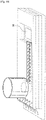
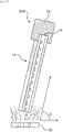
- a fluid vaporization device 10 having a fluid supply 12, a bubble pump 14, and a vaporizer 16 (fluid vaporization heater).
- the device 10 is configured so that the bubble pump 14 desirably transports fluid from the fluid supply 12 directly onto the vaporizer 16.
- the device 10 is incorporated onto a printed circuit board 18 to provide a single assembly containing the fluid supply 12, the bubble pump 14, and the vaporizer 16.
- the bubble pump 14 has a length axis that generally defines a plane, and the vaporizer 16 is provided on a substrate generally defining a plane.
- the plane defined by the bubble pump 14 and the plane defined by the vaporizer 16 are substantially parallel to one another.
- the fluid supply 12 is configured as a fluid storage vessel located on a cover substrate 20 of the bubble pump 14.
- the fluid supply 12 is charged with a desired vaporizable fluid and is generally vented to the atmosphere and contains a desired volume of a fluid, typically a liquid at ambient conditions.
- the fluid may be a liquid of a type utilized for vapes or e-cigarettes in a volumetric amount suitable for such usage.
- a supply inlet 22 is defined between the fluid supply 12 and the cover substrate 20 to provide a fluidic path for desired travel of fluid from the fluid supply12 to the bubble pump 14.
- the bubble pump 14 is configured for pumping fluid from the fluid supply 12 to the vaporizer 16.
- the bubble pump 14 includes an inlet 30, a base substrate 32, flow sequencing resistive heaters 34, and an outlet 36.
- a flow feature layer is initially deposited on the base substrate 32. The flow feature layer is then selectively etched to provide the heaters 34 and to define a flow channel 38.
- the base substrate 32 may be a semiconductor silicon substrate that is suitable for providing bubble pumps and logic circuits thereon.
- the cover substrate 20 may be made of silicon or a polymeric material such as polyimide.
- the resistive heaters 34 and vaporizer 16 may be made of TaAIN, TaAl or other thin film resistor material.
- the preferred material for the flow feature layer for providing the resistive heaters 34 is TaAIN deposited on the base substrate 32 as by sputtering.
- the vaporizer 16 may be formed in a similar manner.
- Electrical connections and logic circuits are integrated onto the device 10 to control and operate the heaters 34 of the bubble pump 14 and the vaporizer 16, and to otherwise control the transfer of fluid from the fluid supply 12 to the vaporizer 16.
- voltage pulses may be applied to the heaters 34 in a desired manner to form and transport thermal bubbles of the fluid along the flow channel 38 to deliver fluid as desired to the vaporizer 16 for vaporization of the delivered fluid.
- Examples of preferred bubble pumps are shown in U.S. Patent No. 8,891,949, issued November 18, 2014 , entitled Micro-fluidic pump, and incorporated by reference herein in its entirety.
- a voltage pulse is applied to each of the heaters 34 in sequence to generate thermal bubbles in a predetermined manner.
- every heater 34 can form a bubble from the inlet 30 to the outlet 36 of the channel 38 in sequence to transport fluid as desired from the supply 12 to the vaporization heater 16.
- Each heater 34 is also desirably permitted to cool down before the next firing sequence in order to prevent overheating and boiling of fluid within the bubble bump 14.
- the vaporizer 16 is configured as a microfluidic electrical heating element designed specifically to vaporize the fluid received from the fluid supply 12.
- the vaporizer 16 is located adjacent and below the outlet 36 of the bubble pump 14.
- a slot or other flow path is formed through the circuit board 18 for travel of fluid from the outlet 36 of the bubble pump 14 to the vaporizer 16.
- the vaporizer 16 has a heated fluid contact surface that is open and exposed to the air or other local environment. The heated fluid contact surface heats the received fluid to vaporize the received fluid into the atmosphere or other local environment.
- FIG. 4 there is shown an alternate embodiment of a fluid vaporization device 50.
- the device 50 has a fluid supply 52, a bubble pump 54, and a vaporizer 56.
- the fluid supply 52 and the bubble pump 54 are incorporated onto a printed circuit board 58.
- the fluid supply 52, the bubble pump 54, and the vaporizer 56 substantially correspond to the fluid supply 12, the bubble pump 14, and the vaporizer 16.
- the vaporizer 56 is spaced from the end of the circuit board 58 so as to be in a plane that is substantially perpendicular to a fluid flow plane defined by the bubble pump 54.
- FIGS. 5 and 6 there is shown another alternate embodiment of a fluid vaporization device 60.
- the device 60 substantially corresponds to the device 50, and includes the fluid supply 52, bubble pump 54, and the vaporizer 56, except the circuit board 58 with the bubble pump 54 thereon is oriented at an angle A or an angle A' or both relative to a plane defined by the vaporizer 56.
- the angles A and A' may each vary from about 0 degrees to about 90 degrees.
- the depicted angles are provided to show that the angular orientation between the bubble pump 54 and the vaporizer 56 may be varied in any of the three dimensions.
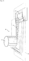
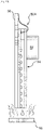
- FIG. 7 there is shown yet another embodiment of a fluid vaporization device 70.
- the device 70 substantially corresponds to the device 50, and includes the bubble pump 54, the vaporizer 56 and the circuit board 58.
- a fluid supply 72 is provided having an inlet 74 located at a distal end of the assembly of the bubble pump 54 and the circuit board 58 opposite the vaporizer 56.
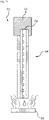
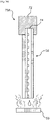
- FIG. 8 there is shown another alternate embodiment of a fluid vaporization device 80.
- the device 60 substantially corresponds to the device 70, and includes the fluid supply 72, bubble pump 54, and the vaporizer 56, except the circuit board 58 with the bubble pump 54 thereon is oriented at an angle B relative to the plane defined by the vaporizer 56.
- the angle B may vary from about 0 degrees to about 90 degrees.
- the angle B may be in one or more dimensions, as explained in connection with the angles A and A' of FIGS. 5 and 6 .
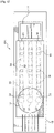
- FIGS. 9 and 10 there is shown another alternate embodiment of a fluid vaporization device 90.
- the device 90 substantially corresponds to the device 10, and includes the fluid supply 12, the bubble pump 14, the vaporizer 16, and the circuit board 18. However, the device 90 is constructed with the bubble pump 14 and the vaporizer 16 fabricated on the same substrate.
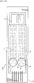
- a fluid vaporization device 10A having a fluid supply 12, a plurality of bubble pumps 14, and a vaporizer 16.
- the device 10A is configured so that the bubble pumps 14 desirably transport fluid from the fluid supply 12 directly onto the vaporizer 16.
- the device 10A is incorporated onto a printed circuit board 18 to provide a single assembly containing the fluid supply 12, the bubble pumps 14, and the vaporizer 16.
- Each of the bubble pumps 14 has a length axis that generally defines a plane, and the vaporizer 16 is provided on a substrate generally defining a plane.
- the common plane defined by the bubble pumps 14 and the plane defined by the vaporizer 16 are substantially parallel to one another.
- the fluid supply 12 is configured as a fluid storage vessel located on a cover substrate 20 of each of the bubble pumps 14.
- the fluid supply 12 is charged with a desired vaporizable fluid and is generally vented to the atmosphere and contains a desired volume of a fluid, typically a liquid at ambient conditions.
- the fluid may be a liquid of a type utilized for vapes or e-cigarettes in a volumetric amount suitable for such usage.
- a supply inlet 22 is defined between the fluid supply 12 and the cover substrate 20 to provide a fluidic path for desired travel of fluid from the fluid supply12 to each of the bubble pumps 14.
- each bubble pump 14 is configured for pumping fluid from the fluid supply 12 to the vaporizer 16.
- each bubble pump 14 includes an inlet 30, a base substrate 32, flow sequencing resistive heaters 34, and an outlet 36.
- a flow feature layer is initially deposited on the base substrate 32.
- the flow feature layer is then selectively etched to provide the heaters 34 and to define a flow channel 38.
- the base substrate 32 may be a semiconductor silicon substrate that is suitable for providing bubble pumps and logic circuits thereon.
- the cover substrate 20 may be made of silicon or a polymeric material such as polyimide.
- the resistive heaters 34 and vaporizer 16 may be made of TaAIN, TaAI or other thin film resistor material.
- the preferred material for the flow feature layer for providing the resistive heaters 34 is TaAIN deposited on the base substrate 32 as by sputtering.
- the vaporizer 16 may be formed in a similar manner.
- Electrical connections and logic circuits are integrated onto the device 10A to control and operate the heaters 34 of the bubble pumps 14 and the vaporizer 16, and to otherwise control the transfer of fluid from the fluid supply 12 to the vaporizer 16.
- voltage pulses may be applied to the heaters 34 in a desired manner to form and transport thermal bubbles of the fluid along the flow channel 38 to deliver fluid as desired to the vaporizer 16 for vaporization of the delivered fluid.
- Examples of preferred bubble pumps are shown in U.S. Patent No. 8,891,949, issued November 18, 2014 , entitled Micro-fluidic pump, and incorporated by reference herein in its entirety.
- a voltage pulse is applied to each of the heaters 34 in sequence to generate thermal bubbles in a predetermined manner.
- every heater 34 can form a bubble from the inlet 30 to the outlet 36 of the channel 38 in sequence to transport fluid as desired from the supply 12 to the vaporization heater 16.
- Each heater 34 is also desirably permitted to cool down before the next firing sequence in order to prevent overheating and boiling of fluid within the bubble bump 14.
- the bubble pumps 14 may be operated to cooperate to provide transport of fluid to the vaporizer 16.
- the vaporizer 16 is configured as a microfluidic electrical heating element designed specifically to vaporize the fluid received from the fluid supply 12.
- the vaporizer 16 is located adjacent and below the outlets 36 of the bubble pumps 14.
- a slot or other flow path is formed through the circuit board 18 for travel of fluid from the outlet 36 of the bubble pump 14 to the vaporizer 16.
- the vaporizer 16 has a heated fluid contact surface that is open and exposed to the air or other local environment. The heated fluid contact surface heats the received fluid to vaporize the received fluid into the atmosphere or other local environment. It will be appreciated that the vaporizer 16 may be provided by a single or multiple vaporizer structures.
- FIG. 13 there is shown an alternate embodiment of a fluid vaporization device 50A.
- the device 50A has a fluid supply 52, bubble pumps 54, and a vaporizer 56.
- the fluid supply 52 and the bubble pumps 54 are incorporated onto a printed circuit board 58.
- the fluid supply 52, the bubble pumps 54, and the vaporizer 56 substantially correspond to the fluid supply 12, the bubble pumps 14, and the vaporizer 16.
- the vaporizer 56 is spaced from the end of the circuit board 58 so as to be in a plane that is substantially perpendicular to a fluid flow plane defined by the bubble pumps 54.
- FIGS. 14 and 15 there is shown another alternate embodiment of a fluid vaporization device 60A.
- the device 60A substantially corresponds to the device 50A, and includes the fluid supply 52, bubble pumps 54, and the vaporizer 56, except the circuit board 58 with the bubble pump 54 thereon is oriented at an angle C or an angle C' or both relative to a plane defined by the vaporizer 56.
- the angles C and C' may each vary from about 0 degrees to about 90 degrees.
- the depicted angles are provided to show that the angular orientation between the bubble pumps 54 and the vaporizer 56 may be varied in any of the three dimensions.
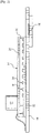
- FIG. 16 there is shown yet another embodiment of a fluid vaporization device 70A.
- the device 70A substantially corresponds to the device 50A, and includes the bubble pumps 54, the vaporizer 56 and the circuit board 58.
- a fluid supply 72 is provided having an inlet 74 located at a distal end of the assembly of the bubble pump 54 and the circuit board 58 opposite the vaporizer 56.
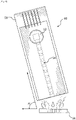
- FIG. 17 there is shown another alternate embodiment of a fluid vaporization device 80A.
- the device 60A substantially corresponds to the device 70A, and includes the fluid supply 72, bubble pumps 54, and the vaporizer 56, except the circuit board 58 with the bubble pumps 54 thereon is oriented at an angle D relative to the plane defined by the vaporizer 56.
- the angle D may vary from about 0 degrees to about 90 degrees.
- the angle D may be in one or more dimensions, as explained in connection with the angles C and C' of FIGS. 14 and 15 .
- FIG. 18 there is shown another alternate embodiment of a fluid vaporization device 90A.
- the device 90A substantially corresponds to the device 10A, except the device 90A includes the plurality of bubble pumps 14 in flow communication with a plurality of the fluid supplies 12. It will be appreciated that each of the fluid supplies 12 may include a different vaporizable fluid or fluids having different characteristics or mixtures of fluids.
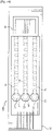
- FIG. 19 there is shown another alternate embodiment of a fluid vaporization device 100.
- the device 100 substantially corresponds to the device 90A, except the device 110 includes the plurality of bubble pumps 14 with the same number of fluid supplies 12.
- Each of the bubble pumps 14 is in flow communication with a corresponding one of the fluid supplies 12.
- each of the fluid supplies 12 may include a different fluid or fluids having different characteristics or mixtures of fluids.
- FIGS. 20 and 21 there is shown another alternate embodiment of a fluid vaporization device 110.
- the device 110 substantially corresponds to the device 10A, and includes the fluid supply 12, the bubble pumps 14, the vaporizer 16, and the circuit board 18. However, the device 110 is constructed with the bubble pumps 14 and the vaporizer 16 fabricated on the same substrate.
Applications Claiming Priority (3)
| Application Number | Priority Date | Filing Date | Title |
|---|---|---|---|
| US14/976,067 US10344747B2 (en) | 2015-12-21 | 2015-12-21 | Method and apparatus for metering and vaporizing a fluid |
| US14/976,053 US10334879B2 (en) | 2015-12-21 | 2015-12-21 | Method and apparatus for metering and vaporizing a fluid |
| PCT/JP2016/087716 WO2017110713A1 (en) | 2015-12-21 | 2016-12-19 | Vaporization device and method of vaporizing fluid |
Publications (3)
| Publication Number | Publication Date |
|---|---|
| EP3394510A1 EP3394510A1 (en) | 2018-10-31 |
| EP3394510A4 EP3394510A4 (en) | 2019-10-09 |
| EP3394510B1 true EP3394510B1 (en) | 2022-09-14 |
Family
ID=59090353
Family Applications (1)
| Application Number | Title | Priority Date | Filing Date |
|---|---|---|---|
| EP16878602.8A Active EP3394510B1 (en) | 2015-12-21 | 2016-12-19 | Vaporization device |
Country Status (4)
| Country | Link |
|---|---|
| EP (1) | EP3394510B1 (zh) |
| JP (1) | JP6806149B2 (zh) |
| CN (1) | CN108291713B (zh) |
| WO (1) | WO2017110713A1 (zh) |
Families Citing this family (19)
| Publication number | Priority date | Publication date | Assignee | Title |
|---|---|---|---|---|
| US10244793B2 (en) | 2005-07-19 | 2019-04-02 | Juul Labs, Inc. | Devices for vaporization of a substance |
| US10279934B2 (en) | 2013-03-15 | 2019-05-07 | Juul Labs, Inc. | Fillable vaporizer cartridge and method of filling |
| USD825102S1 (en) | 2016-07-28 | 2018-08-07 | Juul Labs, Inc. | Vaporizer device with cartridge |
| US10058129B2 (en) | 2013-12-23 | 2018-08-28 | Juul Labs, Inc. | Vaporization device systems and methods |
| USD842536S1 (en) | 2016-07-28 | 2019-03-05 | Juul Labs, Inc. | Vaporizer cartridge |
| US20160366947A1 (en) | 2013-12-23 | 2016-12-22 | James Monsees | Vaporizer apparatus |
| US10159282B2 (en) | 2013-12-23 | 2018-12-25 | Juul Labs, Inc. | Cartridge for use with a vaporizer device |
| KR102256889B1 (ko) | 2013-12-23 | 2021-05-31 | 쥴 랩스, 인크. | 기화 디바이스 시스템 및 방법 |
| US10076139B2 (en) | 2013-12-23 | 2018-09-18 | Juul Labs, Inc. | Vaporizer apparatus |
| KR102627987B1 (ko) | 2014-12-05 | 2024-01-22 | 쥴 랩스, 인크. | 교정된 투여량 제어 |
| EP3419443A4 (en) | 2016-02-11 | 2019-11-20 | Juul Labs, Inc. | SAFE MOUNTING OF CARTRIDGES FOR EVAPORATOR DEVICES |
| DE202017007467U1 (de) | 2016-02-11 | 2021-12-08 | Juul Labs, Inc. | Befüllbare Verdampferkartusche |
| US10405582B2 (en) | 2016-03-10 | 2019-09-10 | Pax Labs, Inc. | Vaporization device with lip sensing |
| USD849996S1 (en) | 2016-06-16 | 2019-05-28 | Pax Labs, Inc. | Vaporizer cartridge |
| USD851830S1 (en) | 2016-06-23 | 2019-06-18 | Pax Labs, Inc. | Combined vaporizer tamp and pick tool |
| USD836541S1 (en) | 2016-06-23 | 2018-12-25 | Pax Labs, Inc. | Charging device |
| US11278058B2 (en) | 2017-08-28 | 2022-03-22 | Juul Labs, Inc. | Wick for vaporizer device |
| USD887632S1 (en) | 2017-09-14 | 2020-06-16 | Pax Labs, Inc. | Vaporizer cartridge |
| DE102017123867A1 (de) | 2017-10-13 | 2019-04-18 | Hauni Maschinenbau Gmbh | Inhalator, insbesondere elektronisches Zigarettenprodukt, und Computerprogrammprodukt |
Family Cites Families (15)
| Publication number | Priority date | Publication date | Assignee | Title |
|---|---|---|---|---|
| JPS6479542A (en) * | 1987-09-21 | 1989-03-24 | Chubu Electric Power | Hot-water supplier |
| JPH0610900A (ja) * | 1992-04-27 | 1994-01-21 | Canon Inc | 液体移動方法及び移動装置ならびにこれを利用した測定装置 |
| JPH09196302A (ja) * | 1996-01-24 | 1997-07-29 | Matsushita Electric Ind Co Ltd | 蒸気発生装置 |
| US6637379B2 (en) * | 2000-04-24 | 2003-10-28 | A. Western Pump & Dredge, Inc. | Accelerated water evaporation system |
| US20030175947A1 (en) * | 2001-11-05 | 2003-09-18 | Liu Robin Hui | Enhanced mixing in microfluidic devices |
| US6655924B2 (en) * | 2001-11-07 | 2003-12-02 | Intel Corporation | Peristaltic bubble pump |
| JP3894066B2 (ja) | 2002-07-30 | 2007-03-14 | 松下電器産業株式会社 | 蒸気発生装置及び蒸気発生装置を備えた加熱調理装置 |
| US7065907B2 (en) * | 2002-08-26 | 2006-06-27 | Koninklijke Philips Electronics N.V. | Electric steaming device |
| CN100434857C (zh) * | 2003-01-21 | 2008-11-19 | 三菱电机株式会社 | 气泡泵型热输送设备 |
| US8891949B2 (en) | 2012-02-03 | 2014-11-18 | Lexmark International, Inc. | Micro-fluidic pump |
| CN203147722U (zh) * | 2012-05-21 | 2013-08-21 | 大卫·梅纳什斯 | 蒸汽加热器和壶 |
| US9387478B2 (en) * | 2012-08-17 | 2016-07-12 | Lexmark International, Inc. | Micro-fluidic modules on a chip for diagnostic applications |
| US8881737B2 (en) * | 2012-09-04 | 2014-11-11 | R.J. Reynolds Tobacco Company | Electronic smoking article comprising one or more microheaters |
| US9801415B2 (en) * | 2014-07-11 | 2017-10-31 | POSIFA Microsytems, Inc. | MEMS vaporizer |
| WO2016064684A1 (en) * | 2014-10-20 | 2016-04-28 | Numerical Design, Inc. | Microfluidic-based apparatus and method for vaporization of liquids |
-
2016
- 2016-12-19 EP EP16878602.8A patent/EP3394510B1/en active Active
- 2016-12-19 JP JP2018517641A patent/JP6806149B2/ja active Active
- 2016-12-19 CN CN201680070693.9A patent/CN108291713B/zh active Active
- 2016-12-19 WO PCT/JP2016/087716 patent/WO2017110713A1/en active Application Filing
Also Published As
| Publication number | Publication date |
|---|---|
| WO2017110713A1 (en) | 2017-06-29 |
| EP3394510A4 (en) | 2019-10-09 |
| JP6806149B2 (ja) | 2021-01-06 |
| CN108291713A (zh) | 2018-07-17 |
| EP3394510A1 (en) | 2018-10-31 |
| JP2019504269A (ja) | 2019-02-14 |
| CN108291713B (zh) | 2020-06-19 |
Similar Documents
| Publication | Publication Date | Title |
|---|---|---|
| EP3394510B1 (en) | Vaporization device | |
| JP2019533462A (ja) | 吸入器用の蒸発器ユニット及び蒸発器ユニットを制御するための方法 | |
| US10440996B2 (en) | Atomizing assembly for use in an aerosol-generating system | |
| US20230024534A1 (en) | Microfluidic dispenser device for delivering inhalable substances | |
| JP6868951B2 (ja) | 蒸気供給のためのシステムおよび方法 | |
| CN109536923B (zh) | 多托盘压载抽蒸气系统 | |
| US10759168B2 (en) | Support substrates for microfluidic die | |
| TWI322247B (en) | Delivery systems for efficient vaporization of precursor source material | |
| US10334879B2 (en) | Method and apparatus for metering and vaporizing a fluid | |
| TW201709444A (zh) | 用於積體電路和裝置層級冷卻的微管 | |
| US10344747B2 (en) | Method and apparatus for metering and vaporizing a fluid | |
| US20240080942A1 (en) | Vaporiser assembly for an aerosol-generating system | |
| US11778696B2 (en) | Vaporiser assembly for an aerosol-generating system | |
| CN113873904A (zh) | 微型蒸发器的筒体和平板加热元件的装配结构 | |
| KR20160026285A (ko) | 반도체 장비용 기화장치 | |
| CN108350870B (zh) | 微流体装置 | |
| WO2017131614A1 (en) | Fluid device |
Legal Events
| Date | Code | Title | Description |
|---|---|---|---|
| STAA | Information on the status of an ep patent application or granted ep patent |
Free format text: STATUS: THE INTERNATIONAL PUBLICATION HAS BEEN MADE |
|
| PUAI | Public reference made under article 153(3) epc to a published international application that has entered the european phase |
Free format text: ORIGINAL CODE: 0009012 |
|
| STAA | Information on the status of an ep patent application or granted ep patent |
Free format text: STATUS: REQUEST FOR EXAMINATION WAS MADE |
|
| 17P | Request for examination filed |
Effective date: 20180613 |
|
| AK | Designated contracting states |
Kind code of ref document: A1 Designated state(s): AL AT BE BG CH CY CZ DE DK EE ES FI FR GB GR HR HU IE IS IT LI LT LU LV MC MK MT NL NO PL PT RO RS SE SI SK SM TR |
|
| AX | Request for extension of the european patent |
Extension state: BA ME |
|
| DAV | Request for validation of the european patent (deleted) | ||
| DAX | Request for extension of the european patent (deleted) | ||
| A4 | Supplementary search report drawn up and despatched |
Effective date: 20190911 |
|
| RIC1 | Information provided on ipc code assigned before grant |
Ipc: F22B 1/28 20060101ALI20190905BHEP Ipc: B81B 1/00 20060101ALI20190905BHEP Ipc: F04B 19/00 20060101ALI20190905BHEP Ipc: B81B 7/00 20060101ALI20190905BHEP Ipc: B01L 3/00 20060101ALI20190905BHEP Ipc: F22B 27/00 20060101AFI20190905BHEP |
|
| STAA | Information on the status of an ep patent application or granted ep patent |
Free format text: STATUS: EXAMINATION IS IN PROGRESS |
|
| STAA | Information on the status of an ep patent application or granted ep patent |
Free format text: STATUS: EXAMINATION IS IN PROGRESS |
|
| 17Q | First examination report despatched |
Effective date: 20201110 |
|
| STAA | Information on the status of an ep patent application or granted ep patent |
Free format text: STATUS: EXAMINATION IS IN PROGRESS |
|
| RIC1 | Information provided on ipc code assigned before grant |
Ipc: F04B 19/24 20060101ALI20220421BHEP Ipc: F04B 19/06 20060101ALI20220421BHEP Ipc: A61M 15/06 20060101ALI20220421BHEP Ipc: A61M 15/00 20060101ALI20220421BHEP Ipc: A61M 11/04 20060101ALI20220421BHEP Ipc: B01L 3/00 20060101ALI20220421BHEP Ipc: F04B 19/00 20060101ALI20220421BHEP Ipc: B81B 7/00 20060101ALI20220421BHEP Ipc: B81B 1/00 20060101ALI20220421BHEP Ipc: F22B 1/28 20060101ALI20220421BHEP Ipc: F22B 27/00 20060101AFI20220421BHEP |
|
| GRAP | Despatch of communication of intention to grant a patent |
Free format text: ORIGINAL CODE: EPIDOSNIGR1 |
|
| STAA | Information on the status of an ep patent application or granted ep patent |
Free format text: STATUS: GRANT OF PATENT IS INTENDED |
|
| INTG | Intention to grant announced |
Effective date: 20220620 |
|
| GRAS | Grant fee paid |
Free format text: ORIGINAL CODE: EPIDOSNIGR3 |
|
| GRAA | (expected) grant |
Free format text: ORIGINAL CODE: 0009210 |
|
| STAA | Information on the status of an ep patent application or granted ep patent |
Free format text: STATUS: THE PATENT HAS BEEN GRANTED |
|
| AK | Designated contracting states |
Kind code of ref document: B1 Designated state(s): AL AT BE BG CH CY CZ DE DK EE ES FI FR GB GR HR HU IE IS IT LI LT LU LV MC MK MT NL NO PL PT RO RS SE SI SK SM TR |
|
| REG | Reference to a national code |
Ref country code: GB Ref legal event code: FG4D |
|
| REG | Reference to a national code |
Ref country code: CH Ref legal event code: EP |
|
| REG | Reference to a national code |
Ref country code: DE Ref legal event code: R096 Ref document number: 602016075073 Country of ref document: DE |
|
| REG | Reference to a national code |
Ref country code: IE Ref legal event code: FG4D |
|
| REG | Reference to a national code |
Ref country code: AT Ref legal event code: REF Ref document number: 1518910 Country of ref document: AT Kind code of ref document: T Effective date: 20221015 |
|
| REG | Reference to a national code |
Ref country code: LT Ref legal event code: MG9D |
|
| REG | Reference to a national code |
Ref country code: NL Ref legal event code: MP Effective date: 20220914 |
|
| PG25 | Lapsed in a contracting state [announced via postgrant information from national office to epo] |
Ref country code: SE Free format text: LAPSE BECAUSE OF FAILURE TO SUBMIT A TRANSLATION OF THE DESCRIPTION OR TO PAY THE FEE WITHIN THE PRESCRIBED TIME-LIMIT Effective date: 20220914 Ref country code: RS Free format text: LAPSE BECAUSE OF FAILURE TO SUBMIT A TRANSLATION OF THE DESCRIPTION OR TO PAY THE FEE WITHIN THE PRESCRIBED TIME-LIMIT Effective date: 20220914 Ref country code: NO Free format text: LAPSE BECAUSE OF FAILURE TO SUBMIT A TRANSLATION OF THE DESCRIPTION OR TO PAY THE FEE WITHIN THE PRESCRIBED TIME-LIMIT Effective date: 20221214 Ref country code: LV Free format text: LAPSE BECAUSE OF FAILURE TO SUBMIT A TRANSLATION OF THE DESCRIPTION OR TO PAY THE FEE WITHIN THE PRESCRIBED TIME-LIMIT Effective date: 20220914 Ref country code: LT Free format text: LAPSE BECAUSE OF FAILURE TO SUBMIT A TRANSLATION OF THE DESCRIPTION OR TO PAY THE FEE WITHIN THE PRESCRIBED TIME-LIMIT Effective date: 20220914 Ref country code: FI Free format text: LAPSE BECAUSE OF FAILURE TO SUBMIT A TRANSLATION OF THE DESCRIPTION OR TO PAY THE FEE WITHIN THE PRESCRIBED TIME-LIMIT Effective date: 20220914 |
|
| REG | Reference to a national code |
Ref country code: AT Ref legal event code: MK05 Ref document number: 1518910 Country of ref document: AT Kind code of ref document: T Effective date: 20220914 |
|
| PG25 | Lapsed in a contracting state [announced via postgrant information from national office to epo] |
Ref country code: HR Free format text: LAPSE BECAUSE OF FAILURE TO SUBMIT A TRANSLATION OF THE DESCRIPTION OR TO PAY THE FEE WITHIN THE PRESCRIBED TIME-LIMIT Effective date: 20220914 Ref country code: GR Free format text: LAPSE BECAUSE OF FAILURE TO SUBMIT A TRANSLATION OF THE DESCRIPTION OR TO PAY THE FEE WITHIN THE PRESCRIBED TIME-LIMIT Effective date: 20221215 |
|
| PG25 | Lapsed in a contracting state [announced via postgrant information from national office to epo] |
Ref country code: SM Free format text: LAPSE BECAUSE OF FAILURE TO SUBMIT A TRANSLATION OF THE DESCRIPTION OR TO PAY THE FEE WITHIN THE PRESCRIBED TIME-LIMIT Effective date: 20220914 Ref country code: RO Free format text: LAPSE BECAUSE OF FAILURE TO SUBMIT A TRANSLATION OF THE DESCRIPTION OR TO PAY THE FEE WITHIN THE PRESCRIBED TIME-LIMIT Effective date: 20220914 Ref country code: PT Free format text: LAPSE BECAUSE OF FAILURE TO SUBMIT A TRANSLATION OF THE DESCRIPTION OR TO PAY THE FEE WITHIN THE PRESCRIBED TIME-LIMIT Effective date: 20230116 Ref country code: ES Free format text: LAPSE BECAUSE OF FAILURE TO SUBMIT A TRANSLATION OF THE DESCRIPTION OR TO PAY THE FEE WITHIN THE PRESCRIBED TIME-LIMIT Effective date: 20220914 Ref country code: CZ Free format text: LAPSE BECAUSE OF FAILURE TO SUBMIT A TRANSLATION OF THE DESCRIPTION OR TO PAY THE FEE WITHIN THE PRESCRIBED TIME-LIMIT Effective date: 20220914 Ref country code: AT Free format text: LAPSE BECAUSE OF FAILURE TO SUBMIT A TRANSLATION OF THE DESCRIPTION OR TO PAY THE FEE WITHIN THE PRESCRIBED TIME-LIMIT Effective date: 20220914 |
|
| PG25 | Lapsed in a contracting state [announced via postgrant information from national office to epo] |
Ref country code: SK Free format text: LAPSE BECAUSE OF FAILURE TO SUBMIT A TRANSLATION OF THE DESCRIPTION OR TO PAY THE FEE WITHIN THE PRESCRIBED TIME-LIMIT Effective date: 20220914 Ref country code: PL Free format text: LAPSE BECAUSE OF FAILURE TO SUBMIT A TRANSLATION OF THE DESCRIPTION OR TO PAY THE FEE WITHIN THE PRESCRIBED TIME-LIMIT Effective date: 20220914 Ref country code: IS Free format text: LAPSE BECAUSE OF FAILURE TO SUBMIT A TRANSLATION OF THE DESCRIPTION OR TO PAY THE FEE WITHIN THE PRESCRIBED TIME-LIMIT Effective date: 20230114 Ref country code: EE Free format text: LAPSE BECAUSE OF FAILURE TO SUBMIT A TRANSLATION OF THE DESCRIPTION OR TO PAY THE FEE WITHIN THE PRESCRIBED TIME-LIMIT Effective date: 20220914 |
|
| REG | Reference to a national code |
Ref country code: DE Ref legal event code: R097 Ref document number: 602016075073 Country of ref document: DE |
|
| PG25 | Lapsed in a contracting state [announced via postgrant information from national office to epo] |
Ref country code: NL Free format text: LAPSE BECAUSE OF FAILURE TO SUBMIT A TRANSLATION OF THE DESCRIPTION OR TO PAY THE FEE WITHIN THE PRESCRIBED TIME-LIMIT Effective date: 20220914 Ref country code: AL Free format text: LAPSE BECAUSE OF FAILURE TO SUBMIT A TRANSLATION OF THE DESCRIPTION OR TO PAY THE FEE WITHIN THE PRESCRIBED TIME-LIMIT Effective date: 20220914 |
|
| PLBE | No opposition filed within time limit |
Free format text: ORIGINAL CODE: 0009261 |
|
| STAA | Information on the status of an ep patent application or granted ep patent |
Free format text: STATUS: NO OPPOSITION FILED WITHIN TIME LIMIT |
|
| PG25 | Lapsed in a contracting state [announced via postgrant information from national office to epo] |
Ref country code: DK Free format text: LAPSE BECAUSE OF FAILURE TO SUBMIT A TRANSLATION OF THE DESCRIPTION OR TO PAY THE FEE WITHIN THE PRESCRIBED TIME-LIMIT Effective date: 20220914 |
|
| REG | Reference to a national code |
Ref country code: CH Ref legal event code: PL |
|
| 26N | No opposition filed |
Effective date: 20230615 |
|
| GBPC | Gb: european patent ceased through non-payment of renewal fee |
Effective date: 20221219 |
|
| REG | Reference to a national code |
Ref country code: BE Ref legal event code: MM Effective date: 20221231 |
|
| PG25 | Lapsed in a contracting state [announced via postgrant information from national office to epo] |
Ref country code: SI Free format text: LAPSE BECAUSE OF FAILURE TO SUBMIT A TRANSLATION OF THE DESCRIPTION OR TO PAY THE FEE WITHIN THE PRESCRIBED TIME-LIMIT Effective date: 20220914 Ref country code: LU Free format text: LAPSE BECAUSE OF NON-PAYMENT OF DUE FEES Effective date: 20221219 |
|
| PG25 | Lapsed in a contracting state [announced via postgrant information from national office to epo] |
Ref country code: LI Free format text: LAPSE BECAUSE OF NON-PAYMENT OF DUE FEES Effective date: 20221231 Ref country code: IE Free format text: LAPSE BECAUSE OF NON-PAYMENT OF DUE FEES Effective date: 20221219 Ref country code: GB Free format text: LAPSE BECAUSE OF NON-PAYMENT OF DUE FEES Effective date: 20221219 Ref country code: CH Free format text: LAPSE BECAUSE OF NON-PAYMENT OF DUE FEES Effective date: 20221231 |
|
| PG25 | Lapsed in a contracting state [announced via postgrant information from national office to epo] |
Ref country code: FR Free format text: LAPSE BECAUSE OF NON-PAYMENT OF DUE FEES Effective date: 20221231 Ref country code: BE Free format text: LAPSE BECAUSE OF NON-PAYMENT OF DUE FEES Effective date: 20221231 |
|
| PGFP | Annual fee paid to national office [announced via postgrant information from national office to epo] |
Ref country code: DE Payment date: 20231031 Year of fee payment: 8 |
|
| PG25 | Lapsed in a contracting state [announced via postgrant information from national office to epo] |
Ref country code: HU Free format text: LAPSE BECAUSE OF FAILURE TO SUBMIT A TRANSLATION OF THE DESCRIPTION OR TO PAY THE FEE WITHIN THE PRESCRIBED TIME-LIMIT; INVALID AB INITIO Effective date: 20161219 |