EP3394492B1 - Armaturenanordnung für wellschläuche - Google Patents
Armaturenanordnung für wellschläuche Download PDFInfo
- Publication number
- EP3394492B1 EP3394492B1 EP15828502.3A EP15828502A EP3394492B1 EP 3394492 B1 EP3394492 B1 EP 3394492B1 EP 15828502 A EP15828502 A EP 15828502A EP 3394492 B1 EP3394492 B1 EP 3394492B1
- Authority
- EP
- European Patent Office
- Prior art keywords
- sleeve part
- fitting assembly
- corrugated tube
- fitted
- receiving portion
- Prior art date
- Legal status (The legal status is an assumption and is not a legal conclusion. Google has not performed a legal analysis and makes no representation as to the accuracy of the status listed.)
- Not-in-force
Links
Images


Classifications
-
- F—MECHANICAL ENGINEERING; LIGHTING; HEATING; WEAPONS; BLASTING
- F16—ENGINEERING ELEMENTS AND UNITS; GENERAL MEASURES FOR PRODUCING AND MAINTAINING EFFECTIVE FUNCTIONING OF MACHINES OR INSTALLATIONS; THERMAL INSULATION IN GENERAL
- F16L—PIPES; JOINTS OR FITTINGS FOR PIPES; SUPPORTS FOR PIPES, CABLES OR PROTECTIVE TUBING; MEANS FOR THERMAL INSULATION IN GENERAL
- F16L5/00—Devices for use where pipes, cables or protective tubing pass through walls or partitions
- F16L5/02—Sealing
- F16L5/12—Sealing the pipe being cut in two pieces
-
- F—MECHANICAL ENGINEERING; LIGHTING; HEATING; WEAPONS; BLASTING
- F16—ENGINEERING ELEMENTS AND UNITS; GENERAL MEASURES FOR PRODUCING AND MAINTAINING EFFECTIVE FUNCTIONING OF MACHINES OR INSTALLATIONS; THERMAL INSULATION IN GENERAL
- F16L—PIPES; JOINTS OR FITTINGS FOR PIPES; SUPPORTS FOR PIPES, CABLES OR PROTECTIVE TUBING; MEANS FOR THERMAL INSULATION IN GENERAL
- F16L25/00—Constructive types of pipe joints not provided for in groups F16L13/00 - F16L23/00 ; Details of pipe joints not otherwise provided for, e.g. electrically conducting or insulating means
- F16L25/0036—Joints for corrugated pipes
-
- F—MECHANICAL ENGINEERING; LIGHTING; HEATING; WEAPONS; BLASTING
- F16—ENGINEERING ELEMENTS AND UNITS; GENERAL MEASURES FOR PRODUCING AND MAINTAINING EFFECTIVE FUNCTIONING OF MACHINES OR INSTALLATIONS; THERMAL INSULATION IN GENERAL
- F16L—PIPES; JOINTS OR FITTINGS FOR PIPES; SUPPORTS FOR PIPES, CABLES OR PROTECTIVE TUBING; MEANS FOR THERMAL INSULATION IN GENERAL
- F16L37/00—Couplings of the quick-acting type
- F16L37/08—Couplings of the quick-acting type in which the connection between abutting or axially overlapping ends is maintained by locking members
- F16L37/12—Couplings of the quick-acting type in which the connection between abutting or axially overlapping ends is maintained by locking members using hooks, pawls or other movable or insertable locking members
- F16L37/14—Joints secured by inserting between mating surfaces an element, e.g. a piece of wire, a pin, a chain
- F16L37/142—Joints secured by inserting between mating surfaces an element, e.g. a piece of wire, a pin, a chain where the securing element is inserted tangentially
- F16L37/144—Joints secured by inserting between mating surfaces an element, e.g. a piece of wire, a pin, a chain where the securing element is inserted tangentially the securing element being U-shaped
Definitions
- the present invention relates to a fitting assembly for corrugated tubing.
- Corrugated stainless steel tubing was developed during 1980's in Japan and is today highly growing technology employed among others, in natural gas distribution and electricity wiring applications. Due to flexibility of the wall of such corrugated metal tube, the installation of the metal tubing formed of corrugated tubes is remarkably simpler and easier to carry out than installation of the respective tubing by using traditional metal tubes having straight walls requiring formation of bends in each such locations where the tube line has to change its direction. Among others, for this reason application of the CSST technology has substantially reduced installation time and thus labor costs in all those applications where it has replaced the traditional tubing technologies employing the tubes with a straight wall.
- fitting assemblies or fittings
- a drawback of the presently known fittings is that, in some applications such as in installations of such apparatuses where a corrugated tube is led out from inside a container or casing being filled with pressurized medium (e.g. in heat exchangers and heat accumulators), the components of the known fittings typically remain inside the walls of the pressurized container and hence cannot be monitored by using visual inspection (e.g. in order to determine its condition or need for maintenance) or, in case of failure, repaired without dismantling the cover of such apparatuses.
- visual inspection e.g. in order to determine its condition or need for maintenance
- fitting assemblies for connecting the corrugated tubes with other equipment of installation typically include several components separate from each other such as nuts, sealing rings, washers, locking rings and locking pins and/or corresponding elements. Therefore, many fittings exist that are rather complex in construction and thus cumbersome to install and maintain, especially in such installations where the fitting has to be installed in to the inner side of a container or casing.
- a known assembly for corrugate tubing is disclosed in CH363864A .
- a sealing element is pressed between the inner and outer sleeves for sealing and fixing the corrugate tube.
- the aim of the invention is to provide a fitting assembly by means of which a corrugated tube that has been led out from inside an object (i.e. e.g. a casing or a container) can be realized in such a way that components of the fitting can be placed on the outer side of the object so that visual inspection, servicing and reconditioning of the fitting during its service life is possible without dismantling the cover of the object.
- the aim of the present invention is also to form a fitting assembly for corrugated tubing that is simpler in construction and has less separate components than the known fitting assemblies used for corrugated tubes led out from inside an object such as a casing or a container.
- the aim of the present invention is achieved because in the fitting assembly according to invention, the part of the fitting assembly to which the corrugated tube is sealably attachable, is configured such that when the corrugated tube is attached in to this portion, the corrugated tube extends in the direction of the end of the fitting assembly that will be attached to the opening of the object to which the fitting has been attached. Therefore, when the corrugated tube is attached to a wall of the object, the fitting assembly is located on the outer side of the object if the corrugated tube extends from the opening in to the object.
- the fitting assembly according to invention is described in the independent claim 1.
- the dependent claims 2-10 describe advantageous embodiments of the fitting assembly according to the invention.
- the advantage of the fitting assembly according to present invention is that by means of it, the coupling of a corrugated tubing being led out from inside a casing or a container (typically having pressure that differs from ambient pressure) can be formed in such a way that the components used in the fitting assembly between the corrugated tube and the casing or the container can be realized such manner that all these components remain outside the outer walls of the casing or container and are able to be inspected by visual inspection and, when necessary, repaired or serviced within the lifetime of the apparatus in question. Furthermore, the further advantage of the invention is that installation of corrugated tubing becomes easier, simpler and less time consuming, especially in the case of installations with apparatuses where the corrugated tube is led out from inside a casing or container.
- the embodiments of the fitting assembly according to invention shown in figures 1 to 4 , 5 to 6 and 7 to 8 are fitting assemblies that are intended to be used for leading an corrugated tube through a wall of an object such as a container or casing, so that the corrugated tube extends out from inside the container or casing through its wall.
- Such situation takes place, for instance, with a heat exchanger or heat accumulator, where the heat is exchanged from or to a first heat exchange medium being inside the container or casing, or from or to a second heat exchange medium flowing in a corrugated tube arranged in to the container or casing.
- the corrugated tube is arranged in spiral, zig zag or some other suitable form such that enough heat exchanging surface between the corrugated tube and the first heat exchanging medium is formed to exchange the desired amount of heat from the first heat exchanging medium to the second heat exchanging medium or vice versa.
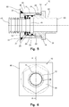
- the fitting assembly 10 shown in figure 1 comprises a first sleeve part 11 and a second sleeve part 12.
- the first sleeve part 11 is a portion of the fitting assembly 10 that is attachable to the edge of an opening 51 formed to an object 50 to which the fitting assembly is to be installed.
- This attachment can be accomplished fixedly by means of soldering or welding, or detachably e.g. by means of a nut and external threads formed on the outer surface of the first sleeve 11 part at its attachment end 13.
- the object 50 to which the first sleeve 11 part is attached is shown by means of square shaped piece of plate to which an opening 51 for the first sleeve part 11 has been formed.
- object 50 is typically a closed container or casing which should be gas and liquid tight i.e. that can have its inner side pressure being higher or lower than ambient pressure effecting outside the object 50.
- the first sleeve part 11 has such type of an attachment end 13 that is configured to be fixedly attachable to the edge of an opening 51 formed to the wall of an object 50 to which the fitting assembly 10 is to be attached.
- the second sleeve part 12 is a portion of the fitting assembly 10 that can be fitted in to the first sleeve part 11 and to which the corrugated tube 40 can be sealably attached.
- the detachable connection between the first sleeve part 11 and the second sleeve part 12 has been configured such that when the second sleeve part 12 is to be fitted and secured in to the first sleeve part, gas or liquid inside the container cannot leak out from the container or casing 50 or in to the container from outside the container or casing through the connection.
- the corrugated tube 40 is connected in to the second sleeve part 12 through a coupling end 19 being in the side of the attachment end 13 of the first sleeve part 11, all components of the fitting assembly leave outside the object 50 in case when the corrugated tube 40 extends out from inside the object 50. This is why the embodiments of the fitting assembly according invention shown in figures 1 to 4 and 5 to 6 are able to be inspected by visual inspection and, when necessary, repaired or serviced without disassembling the object 50 within the lifetime of the entity which both of these both elements are part of.
- the first sleeve part 11 comprises an attachment end 13 and a receiving end 14.
- the attachment end 13 has been configured to be attachable to the opening formed to the object 50 to which the first sleeve part 11 is to be attached.
- the attachment end 13 has been configured to be attachable to the opening formed to the object 50 to which the first sleeve part 11 is to be attached.
- the attachment is accomplished by welding.
- soldering or brazing may be applied as well.
- other suitable attachment methods an means may be applied such as attachment with a ring nut screwed on the threads formed on the sleeve part 11 at the attachment end 13, so that the edge of the opening 51 can be compressed against the fixing corner 15 by means of the ring nut.
- the receiving end 14 is the end through which the second sleeve part 12 is fitted in to the first sleeve part 11.
- the inner diameter of the first sleeve part 11 is larger than the inner diameter at the attachment end 13.
- the portion with enlarged inner diameter extends near the attachment end 13 where it terminates to a locking corner 16 after which the inner diameter of the first sleeve part 11 narrows to approximately the inner diameter that is equal or e.g. some tenths of millimeters larger than outer diameter of the corrugated tube 40 to be fitted in to the fitting assembly 10.
- the first sleeve part 11 further comprise locking apertures 17, through which a retaining pin 18 can be fitted for locking the second sleeve part 12 such that it cannot move out from inside the first sleeve part 11.
- the retaining pin 18 is a U-shaped pin made of metal such as steel.
- retaining pins having other shapes and made of some other suitable material may also be used.
- one U-shaped pin may be replaced by one or more straight or L-shaped pins that can be fitted through the apertures 17, number of which can be two or more depending on the type and amount of retaining pins employed.
- the retaining pin 18 is fitted through the apertures 17 after the second sleeve part 12 has been fitted in to the first sleeve part 11 in to its intended position. In that position, the parts of the retaining pin 18 being in the first sleeve part 11 remains at the outer side of a retaining corner 21 of the second sleeve part 12 and thus retains the second sleeve part 12 in the first sleeve part 11 as shown in the figures 1, 2 and 4 .
- the retaining corner 21 may be replaced with a suitable retaining groove that is formed on the outer surface of the second sleeve part 12 at the suitable position, such that the second sleeve part 12 is retained in the first sleeve part 11 similarly as in the embodiment shown in the figures 1 to 4 .
- the second sleeve part 12 comprises a coupling end 19 and an extension end 20.
- the coupling end 19 is an end that will be fitted in to the first sleeve part 11 through the receiving end 14 of the first sleeve part 11 when the second sleeve part 12 is assembled in to the first sleeve part 11.
- the inner and outer diameter of the second sleeve part 12 is at the coupling end 19 larger than inner and outer diameter at the extension end 20, i.e. there is a receiving portion 22 that extends from coupling end 19 to the direction of the extension end 20.
- the distance which the receiving portion 22 extends from the coupling end 19 to the direction of extension end 20 is less than the length of the portion of the first sleeve part 11 at the receiving end 14 having larger inner diameter than the inner diameter of the attachment end 13 of the first sleeve part 11 when the second sleeve part 12 is fitted in to its position in to the first sleeve part 11.
- the receiving portion 22 terminates to a retaining corner 21, after which the second sleeve part 12 extends as a terminal portion 23 having, in this embodiment, smaller inner and outer diameter than the inner and outer diameter of the receiving portion 22.
- the aim of this is to form a retaining corner 21, by means of which the movement of the second sleeve part 12 out from the first sleeve part 11 (i.e. in the direction of its extension end 20) can be prevented as described above.
- the retaining corner 21 is positioned such that it will be in the first sleeve part 11 when the second coupling end 19 of the sleeve part 12 is against the locking corner 16 in the first sleeve part 11.
- the receiving portion 22 of the second sleeve part 12 comprises on its outer surface two retaining grooves 24.
- two sealing rings 25 have been introduced between the receiving portion 22 and the inner surface of the first sleeve part 11.
- the aim of the retaining grooves 24 is to retain the sealing rings 25 at the right position on the receiving portion 22 such that the sealing rings 25 provide sealing that prevents leaking of gas or liquid through the connection between the first sleeve part 11 and the second sleeve part 12.
- the number of retaining grooves 24 and sealing rings 25 can vary in different arrangements of the fitting.
- sealing ring 25 between the second sleeve part 12 and the first sleeve part 11, but in such embodiments being designed for demanding applications, three or more sealing rings 25 and retaining grooves 24 may be introduced.
- the receiving portion 22 of the second sleeve part 12 provides also a sealed connection for the corrugated tube 40.
- the corrugated tube 40 will be fitted in to the receiving portion 22 through its coupling end 19. Therefore, the inner diameter of the receiving portion 22 is approximately equal to the outer diameter of the corrugated tube 40.
- the shape of the outer surface of the corrugated tube 40 provides as such retaining grooves for one or more sealing rings 26.
- two sealing rings 26 have been introduced between the corrugated tube 40 and the receiving portion 22 in to which the incoming end 41 of the corrugated tube 40 has been fitted.
- minimum number of sealing rings 26 would be one but alternatively three or more sealing rings 26 may be used in such arrangements where extremely reliable sealing is needed.
- a locking ring 27 has been introduced between the outer surface of the corrugated tube 40 and the locking corner 16 of the first sleeve part 11.
- the corrugated tube 40 has been positioned in respect to receiving portion 22 such that it remains (when the second sleeve part 12 is in its connected position in respect to the first sleeve part 11) between the locking corner 16 of the first sleeve part 11 and the coupling end 19 of the second sleeve part 12.
- the locking corner 16 prevents the incoming end 41 of the corrugated tube 40 from moving in the direction of the object 50 and the coupling end 19 prevents it from moving too far inside the receiving portion 22.
- the terminal portion 23 may have some suitable connecting means to connect the extension end 20 of the second sleeve part 12 with some external tube or other equipment, typically belonging to the system or arrangement which portion the object 50 forms.
- the terminal portion 23 at the extension end 20 may, for instance, comprise outer or inner threads, be weldable, solderable or bondable, or have standard dimensions so that universal tube connectors can be applied for connecting the terminal portion 23 with an external tube or other equipment to which the tubing led from inside the object 50 is intended to be connected.
- the corrugated tube is fitted through the first sleeve part 11 out from its receiving end.
- the sealing rings 26 are assembled on the first two depressions (i.e. narrower portions of the corrugated tube 40) at outer surface of the corrugated tube 40 when counted from the incoming end 41 of the corrugated tube 40 as can be seen from figures 1 and 4 .
- the incoming end 41 of the corrugated tube it is fitted in to the receiving portion 22 such that the third depression sets at the point where it is just in the front of the coupling end 19 of the second sleeve part 12, such that when the locking ring 27 is installed against the coupling end 19 in the following phase, its inner edge is fitted in to the third depression.
- the sealing rings 25 are installed on the second sleeve part 12 to the point of the retaining grooves 24, after which the second sleeve part 12 is fitted in to the first sleeve part 11 to the position shown in figures 1 and 4 .
- the sealing rings 25 can be installed earlier, for instance, before installation of the corrugated tube 40 in to the second sleeve part 12.
- the retaining pin 18 is fitted through the locking apertures 17 of the first sleeve part 11 such that the it remains behind the edge of the retaining corner 21 on the side of extension end 20.
- the retaining pin 18 prevents the second sleeve part 12 from moving out from the first sleeve part 11 through its receiving end 14.
- the corrugated tube 40 extends inside the object 50 from the fitting assembly 10 through the opening 51 such that entire fitting assembly 10 remains outside the object 50.
- the fitting assembly 10 does not have any components inside the object 50 and hence the fitting assembly 10 reaches the object of the invention as described above.
- the disassembly of the fitting assembly 10 according to figures 1 to 4 can be carried out by performing the corresponding disassembling operations in the opposite order as the assembling operations described above.
- Figures 5 and 6 show a second embodiment of the fitting assembly according to invention. This embodiment is similar to embodiment shown in figures 1 to 4 except that the attachment of the second sleeve part 12 in to the first sleeve part 11 has been realized in different manner.
- the retaining pin 18 is replaced with an inner threaded portion 28 formed in the inner surface of the first sleeve part 11, an outer threaded portion 29 on the receiving portion 22 of the second sleeve part 12, and a nut member 30 formed between the extension end 20 and the outer threaded portion 29 of the second sleeve part 12.
- the outer threaded portion 29 having an outer diameter larger than the receiving portion 22, has been arranged to engage with inner threaded portion 28 when the second sleeve part 12 is fitted in to the first sleeve part 11.
- the second sleeve part 12 is screwed in to the first sleeve part 11 such that the coupling end 19 of the second sleeve part 12 abuts against the locking ring 27.
- the edge of the nut member 30 being at the side of receiving portion 22 then abuts against the receiving end 14 of the first sleeve part 11 such that a suitable clearance for locking ring 27 remains between the coupling end 19 of the second sleeve part 12 and the locking corner 16 of the first sleeve part 11.
- the nut member 30 is a standard type of hexagon nut which can be screwed by means of standard tools such as adjustable, fork or socket wrench.
- Figures 7 and 8 show a fitting assembly according to an example.
- the fitting assembly according to figures 7 and 8 differs from embodiment of figures 1 to 4 as well as embodiment of figures 5 to 6 in that the receiving portion 22 of the second sleeve part 12 comprises a fitting section 31 that is fitted in to the corrugated tube 40.
- the fitting section 31 has been arranged to extend from the connection point of the first sleeve part 11 and the second sleeve part 12 a suitable distance in to the corrugated tube 40. Due to this difference the both sealing rings used for ensuring tightness between the corrugated tube 40 and the fitting assembly have been placed on the outer and the inner side of the corrugated tube 40. This will simplify the construction, since any retaining grooves need not to be formed either to the first sleeve part 11 or the second sleeve part 12.
- the fitting assembly according to figures 7 and 8 differs from the embodiments of figures 1 to 4 and 5 to 6 in a way that the first sleeve part 11 and the second sleeve part 12 are to be attached to each other.
- the attachment consists of, in this case, one fixing flange 32 at the receiving end 14 of the first sleeve part 11 and an another fixing flange 33 in between the receiving portion 22 and terminal portion 23 of the second sleeve part 12, by means of which the first sleeve part 11 and the second sleeve part 12 are held together.
- a special binding element 34 is provided in order to secure the fixing flanges 32 and 33 against each other in way shown in the figures 7 and 8 .
- the binding element 34 is a kind of a locking spring that has a base portion 35 and two arc-like branches 36 and 37.
- the shape of the branches 36 and 37 conforms with the outer surface of the first sleeve part 11 and the second sleeve part 12 in the vicinity of the fixing flanges 32 and 33.
- the branch 36 is fitted on one side and the branch 37 on the other side of the first sleeve part 11 and second sleeve part 12 abutting against each other.
- Both branches 36 and 37 include slots 38, through which the abutting fixing flanges 32 ja 33 are to be fitted when the binding element 34 is assembled on to its place where it retains the first sleeve part 11 and the second sleeve part 12 against each other in the above mentioned manner.
- the width of the slots 38 have been designed so that the fixing flanges 32 and 33 can be fitted through the slots 38 only when they are pressed against each other as shown in figure 7 .
- the binding element 34 is preferably made of some enough stiff sheet-like material such as metal, plastic or composite.
- the fitting assembly according to invention can be further realized in many ways being different from the above described embodiments.
- the fitting assembly may be realized such that sealing between the corrugated tube and the fitting assembly would be arranged between the outer surface of the corrugated tube and the inner surface of the first sleeve part.
- the narrower portion extending from the attachment end of the first sleeve part would be longer than in the embodiments shown in the figures 1 to 4 and 5 to 6 .
- the locking ring may be attached between the coupling end of the second sleeve part and the locking corner of the first sleeve part but then the sealing rings between the incoming end being fitted in to the receiving portion of the second sleeve part would not be necessary, although in some embodiments also these could be employed.
- the attachment of the second sleeve part in to the first sleeve part may be accomplished by means of securing means being different from the ones described above.
- the second sleeve part may be secured to the first sleeve part e.g. by means of separate fixing screws fitted through a fixing holes made to a fixing flange formed to the second sleeve part e.g.
- the fixing screws may be screwed in to a threaded holes extending from the receiving end of the first sleeve part in to the direction of the attachment end.
- the material of the fitting assembly may vary in different embodiments of the fitting assembly according to the invention. It is preferably made from some metal such as stainless steel, aluminum, brass or copper. However, also non-metallic materials such as plastic or composite materials may be used. Either the corrugated tubes with which the fitting assembly can be used should not be limited only to corrugated tubes made of some metallic materials such as stainless steel or aluminum.
- the fitting assembly may be applied for connecting of corrugated tubes made of, for instance, plastic or many kinds of composite materials as well.
- fitting assembly according to invention should not be limited to the embodiments described above but can be varied within the scope of the appended claims.
Landscapes
- Engineering & Computer Science (AREA)
- General Engineering & Computer Science (AREA)
- Mechanical Engineering (AREA)
- Quick-Acting Or Multi-Walled Pipe Joints (AREA)
Claims (10)
- Eine Armaturenanordnung (10) für gewellte Rohre, wobei die Armaturenanordnung (10) ein erstes Hülsenteil (11) aufweist, das an ein Objekt (50) anfügbar ist, mit dem ein gewelltes Rohr (40) verbunden wird, und ein zweites Hülsenteil (12), das konfiguriert ist, um in das erste Hülsenteil (11) eingebaut zu werden und an das das gewellte Rohr (40) dichtend angefügt werden kann, und wobei in der Armaturenanordnung (10):- das erste Hülsenteil (11) ein Aufnahmeende (14) zur Aufnahme des zweiten Hülsenteils (12) und ein Befestigungsende (13) aufweist, das an einer Öffnung (51) anfügbar ist, die an einem Objekt (50) ausgebildet ist, an das die Armaturenanordnung (10) angefügt wird;- das zweite Hülsenteil (12) einen Aufnahmeabschnitt (22) aufweist, der dichtend an das erste Hülsenteil (11) anfügbar ist;- die Armaturenanordnung (10) Befestigungsmittel (22, 26, 27) zum Anfügen und Abdichten des gewellten Rohres (40) am zweiten Hülsenteil (12) aufweist, so dass sich, wenn das zweite Hülsenteil (12) am ersten Hülsenteil (11) angefügt ist, das gewellte Rohr (40) außerhalb der Armaturenanordnung (10) durch das Befestigungsende (13) des ersten Hülsenteils (11) erstreckt;- die Armaturenanordnung zwei Dichtungselemente (25) zum Abdichten der Verbindung zwischen dem ersten Hülsenteil (11) und dem zweiten Hülsenteil (12) und/oder dem ersten Hülsenteil (11) und dem gewellten Rohr (40) aufweist, wobei die beiden Dichtungselemente (25) in Nuten des zweiten Hülsenteils (12) angeordnet sind;- die Armaturenanordnung (10) darüber hinaus zwei Dichtungselemente (26) zum Abdichten der Verbindung zwischen dem zweiten Hülsenteil (12) und dem gewellten Rohr (40) aufweist, wobei die beiden Dichtungselemente (26) zum Abdichten der Verbindung zwischen dem zweiten Hülsenteil (12) und dem gewellten Rohr (40) bei Verwendung zwischen den Wellungen des gewellten Rohres (40) angeordnet sind;- die Armaturenanordnung darüber hinaus mindestens ein Befestigungselement (27) der Befestigungsmittel zum Befestigen des gewellten Rohres (40) in der Armaturenanordnung (10) aufweist, so dass das gewellte Rohr (40) mit dem zweiten Hülsenteil (12) dichtend verbunden ist;
wobei- das Befestigungselement (27) ein Verriegelungsring (27) ist, der konfiguriert ist, um in eine Wellung des gewellten Rohres (40) und zwischen der Außenseite des gewellten Rohres (40) und einer Verriegelungsecke (16) des ersten Hülsenteils (11) eingebaut zu werden;- das Kupplungsende (19) des zweiten Hülsenteils (12) an dem Verriegelungsring (27) anliegt;- der Verriegelungsring (27) von den Dichtungselementen (25, 26) getrennt ist und der Verriegelungsring sich in einer aneinanderstoßenden Beziehung zu sowohl dem ersten Hülsenteil (11) als auch dem zweiten Hülsenteil (12) befindet. - Armaturenanordnung (10) gemäß Anspruch 1, wobei die Armaturenanordnung (10) Fixiermittel (17, 18; 28, 29, 30; 32, 33, 34) zum Anfügen des zweiten Hülsenteils (12) auf lösbare Weise an dem ersten Hülsenteil (11) aufweist.
- Armaturenanordnung (10) gemäß Anspruch 2, wobei der Aufnahmeabschnitt (22) einen größeren Innendurchmesser aufweist als der Außendurchmesser des gewellten Rohres (40), das in die Armaturenanordnung (10) eingebaut wird.
- Armaturenanordnung (10) gemäß Anspruch 3, wobei die beiden Dichtungselemente (26) zum Abdichten der Verbindung zwischen dem zweiten Hülsenteil (12) und dem gewellten Rohr (40) konfiguriert sind, um zwischen die Innenseite des zweiten Hülsenteils (12) am Aufnahmeabschnitt (22) und die Außenseite des Abschnitts des gewellten Rohres (40), das in den Aufnahmeabschnitt (22) eingebaut wird, eingebaut zu werden.
- Armaturenanordnung (10) gemäß Anspruch 3 oder 4, wobei das erste Hülsenteil (11) mindestens einen Abschnitt aufweist, bei dem der Innendurchmesser größer als der Außendurchmesser des Aufnahmeabschnitts (22) des zweiten Hülsenteils (12) ist und wobei sich dieser Abschnitt vom Aufnahmeende (13) bis zu einem Verriegelungssteg (16) erstreckt, der von einem Abschnitt mit einem kleineren Innendurchmesser als der Außendurchmesser des Aufnahmeabschnitts (22) gebildet ist.
- Armaturenanordnung (10) gemäß einem der Ansprüche 2 bis 5, wobei die Fixiermittel (17, 18) einen Arretierstift (18) und mindestens zwei Öffnungen (17) aufweisen, die durch die Wand des ersten Hülsenteils (11) derart ausgebildet sind, dass der Arretierstift (18) von außerhalb des ersten Hülsenteils (11) hinter eine Halteecke (21) oder in eine auf der Außenseite des zweiten Hülsenteils (12) ausgebildete Haltenut eingebaut werden kann, und dadurch die Bewegung des zweiten Hülsenteils (12) in Bezug auf das erste Hülsenteil (11) verhindert wird.
- Armaturenanordnung (10) gemäß einem der Ansprüche 2 bis 5, wobei die Fixiermittel (28, 29, 30) Außengewinde (29), die an der Außenseite des zweiten Hülsenteils (12) ausgebildet sind, und Innengewinde (28) aufweisen, die an der Innenseite des ersten Hülsenteils (11) ausgebildet sind, und wobei die Außengewinde (29) des zweiten Hülsenteils (12) konfiguriert sind, um mit den Innengewinden (28) des ersten Hülsenteils (11) in Eingriff zu kommen, wenn das zweite Hülsenteil (12) in das erste Hülsenteil (11) eingebaut wird.
- Armaturenanordnung (10) gemäß Anspruch 2, wobei der Aufnahmeabschnitt (22) einen kleineren Außendurchmesser aufweist als der Innendurchmesser des gewellten Rohres (40), das in die Armaturenanordnung (10) einzubauen ist.
- Armaturenanordnung (10) gemäß Anspruch 8, wobei die beiden Dichtungselemente (25) zum Abdichten der Verbindung zwischen dem ersten Hülsenteil (11) und dem zweiten Hülsenteil (12) und/oder dem ersten Hülsenteil (11) und dem gewellten Rohr (40) konfiguriert sind, um zwischen die Außenfläche des zweiten Hülsenteils (12) am Aufnahmeabschnitt (22) und die Innenseite des gewellten Rohres (40) eingebaut zu werden, welches mit dem Aufnahmeabschnitt (22) des zweiten Hülsenteils (12) verbunden wird.
- Armaturenanordnung (10) gemäß einem der Ansprüche 2, 8 oder 9, wobei die Fixiermittel (32, 33, 34) zwei Fixierflansche (32, 33) aufweisen, einen (32) am ersten Hülsenteil (11) und einen weiteren (33) am zweiten Hülsenteil (12), sowie ein Federelement (34), das lösbar an dem ersten Hülsenteil (11) und dem zweiten Hülsenteil (12) anfügbar ist, und wobei das Federelement (34) konfiguriert ist, um die Fixierflansche (32, 33) gegeneinander zu sichern, um das erste Hülsenteil (11) und das zweite Hülsenteil (12) miteinander zu verbinden.
Priority Applications (1)
| Application Number | Priority Date | Filing Date | Title |
|---|---|---|---|
| PL15828502T PL3394492T3 (pl) | 2015-12-23 | 2015-12-23 | Zespół złączki do rur karbowanych |
Applications Claiming Priority (1)
| Application Number | Priority Date | Filing Date | Title |
|---|---|---|---|
| PCT/FI2015/050941 WO2017109270A1 (en) | 2015-12-23 | 2015-12-23 | A fitting assembly for corrugated tubing |
Publications (2)
| Publication Number | Publication Date |
|---|---|
| EP3394492A1 EP3394492A1 (de) | 2018-10-31 |
| EP3394492B1 true EP3394492B1 (de) | 2019-10-02 |
Family
ID=55229741
Family Applications (1)
| Application Number | Title | Priority Date | Filing Date |
|---|---|---|---|
| EP15828502.3A Not-in-force EP3394492B1 (de) | 2015-12-23 | 2015-12-23 | Armaturenanordnung für wellschläuche |
Country Status (3)
| Country | Link |
|---|---|
| EP (1) | EP3394492B1 (de) |
| PL (1) | PL3394492T3 (de) |
| WO (1) | WO2017109270A1 (de) |
Families Citing this family (1)
| Publication number | Priority date | Publication date | Assignee | Title |
|---|---|---|---|---|
| GB2569190B (en) * | 2017-12-11 | 2019-12-18 | Radius Systems Ltd | Service head adaptor assembly |
Family Cites Families (6)
| Publication number | Priority date | Publication date | Assignee | Title |
|---|---|---|---|---|
| CH363864A (de) * | 1957-12-17 | 1962-08-15 | United Flex Metallic Tubing | Metallrohr-Anschluss |
| US3479069A (en) * | 1967-10-20 | 1969-11-18 | Amseco Corp | Connector assembly |
| US4423891A (en) * | 1981-09-28 | 1984-01-03 | Menges William H | Corrugated hose coupling |
| DE4027818A1 (de) * | 1990-09-01 | 1992-03-05 | Ke Rohrsysteme Umwelttech | Verfahren zum befestigen einer anschlussarmatur am ende eines schraubenlinienfoermig gewellten metallrohres |
| FR2674310B1 (fr) * | 1991-03-22 | 1993-07-02 | Capri Codec Sa | Raccord d'accrochage d'un conduit annele. |
| DE20008148U1 (de) * | 2000-05-05 | 2001-09-06 | Reiku Gmbh | Armatur zum Befestigen eines Wellrohres in einer Wandöffnung |
-
2015
- 2015-12-23 WO PCT/FI2015/050941 patent/WO2017109270A1/en active Application Filing
- 2015-12-23 PL PL15828502T patent/PL3394492T3/pl unknown
- 2015-12-23 EP EP15828502.3A patent/EP3394492B1/de not_active Not-in-force
Non-Patent Citations (1)
| Title |
|---|
| None * |
Also Published As
| Publication number | Publication date |
|---|---|
| WO2017109270A1 (en) | 2017-06-29 |
| PL3394492T3 (pl) | 2020-05-18 |
| EP3394492A1 (de) | 2018-10-31 |
Similar Documents
| Publication | Publication Date | Title |
|---|---|---|
| US8025080B2 (en) | Orifice plate alignment device | |
| US5452922A (en) | Elbow fittings with expanded outer annulus space for double-containment assemblies | |
| US20120186796A1 (en) | Heat exchanger device and use thereof | |
| EP3394492B1 (de) | Armaturenanordnung für wellschläuche | |
| CN101438119B (zh) | 用户可选择的热交换装置及其使用方法 | |
| GB2236822A (en) | Adapter fittings and connectors | |
| CN211739961U (zh) | 衔接和连接组件 | |
| JP2001193886A (ja) | 流体管接続のための配置 | |
| RU2564156C2 (ru) | Фиттинг с фланцами для использования с системой герметизации труб | |
| WO2022008696A1 (en) | Gasket assembly | |
| KR101789912B1 (ko) | 열교환기 튜브 단부의 고정 구조 및 이를 적용한 열교환기 | |
| US6843509B2 (en) | Coupler for use with metal conduits | |
| US6789615B2 (en) | Heat exchanger, in particular for swimming pools | |
| GB2391278A (en) | Pipe Coupling | |
| PL185012B1 (pl) | Zawór wzniosowy o krótkiej konstrukcji | |
| JP2017133589A (ja) | 補修用継手 | |
| DE202005012879U1 (de) | Rohrbündel-Wärmeüberträger | |
| US9488290B2 (en) | Disc check valve system and method | |
| KR102476194B1 (ko) | 분기 파이프를 결합하기 위한 결합구 및 그 체결장치 | |
| CN221099479U (zh) | 一种换热管路系统及分容柜 | |
| CN212006900U (zh) | 热交换器 | |
| US9625068B2 (en) | System and method of a flange seal ring | |
| CN220366075U (zh) | 一种不锈钢管接头 | |
| CN210739613U (zh) | 一种卡压紫铜管件 | |
| US10876670B2 (en) | Blind flange and method of installing same for isolating hazardous energy within a facility |
Legal Events
| Date | Code | Title | Description |
|---|---|---|---|
| STAA | Information on the status of an ep patent application or granted ep patent |
Free format text: STATUS: THE INTERNATIONAL PUBLICATION HAS BEEN MADE |
|
| PUAI | Public reference made under article 153(3) epc to a published international application that has entered the european phase |
Free format text: ORIGINAL CODE: 0009012 |
|
| STAA | Information on the status of an ep patent application or granted ep patent |
Free format text: STATUS: REQUEST FOR EXAMINATION WAS MADE |
|
| 17P | Request for examination filed |
Effective date: 20180705 |
|
| AK | Designated contracting states |
Kind code of ref document: A1 Designated state(s): AL AT BE BG CH CY CZ DE DK EE ES FI FR GB GR HR HU IE IS IT LI LT LU LV MC MK MT NL NO PL PT RO RS SE SI SK SM TR |
|
| AX | Request for extension of the european patent |
Extension state: BA ME |
|
| REG | Reference to a national code |
Ref country code: DE Ref legal event code: R079 Ref document number: 602015039212 Country of ref document: DE Free format text: PREVIOUS MAIN CLASS: F16L0005000000 Ipc: F16L0005120000 |
|
| DAV | Request for validation of the european patent (deleted) | ||
| DAX | Request for extension of the european patent (deleted) | ||
| GRAP | Despatch of communication of intention to grant a patent |
Free format text: ORIGINAL CODE: EPIDOSNIGR1 |
|
| STAA | Information on the status of an ep patent application or granted ep patent |
Free format text: STATUS: GRANT OF PATENT IS INTENDED |
|
| RIC1 | Information provided on ipc code assigned before grant |
Ipc: F16L 37/14 20060101ALI20190328BHEP Ipc: F16L 25/00 20060101ALI20190328BHEP Ipc: F16L 5/12 20060101AFI20190328BHEP |
|
| INTG | Intention to grant announced |
Effective date: 20190429 |
|
| GRAS | Grant fee paid |
Free format text: ORIGINAL CODE: EPIDOSNIGR3 |
|
| GRAA | (expected) grant |
Free format text: ORIGINAL CODE: 0009210 |
|
| STAA | Information on the status of an ep patent application or granted ep patent |
Free format text: STATUS: THE PATENT HAS BEEN GRANTED |
|
| AK | Designated contracting states |
Kind code of ref document: B1 Designated state(s): AL AT BE BG CH CY CZ DE DK EE ES FI FR GB GR HR HU IE IS IT LI LT LU LV MC MK MT NL NO PL PT RO RS SE SI SK SM TR |
|
| REG | Reference to a national code |
Ref country code: GB Ref legal event code: FG4D |
|
| REG | Reference to a national code |
Ref country code: AT Ref legal event code: REF Ref document number: 1186560 Country of ref document: AT Kind code of ref document: T Effective date: 20191015 Ref country code: CH Ref legal event code: EP |
|
| REG | Reference to a national code |
Ref country code: DE Ref legal event code: R096 Ref document number: 602015039212 Country of ref document: DE |
|
| REG | Reference to a national code |
Ref country code: IE Ref legal event code: FG4D |
|
| REG | Reference to a national code |
Ref country code: NL Ref legal event code: FP |
|
| PGFP | Annual fee paid to national office [announced via postgrant information from national office to epo] |
Ref country code: FI Payment date: 20191219 Year of fee payment: 5 Ref country code: NL Payment date: 20191119 Year of fee payment: 5 |
|
| REG | Reference to a national code |
Ref country code: SE Ref legal event code: TRGR |
|
| REG | Reference to a national code |
Ref country code: LT Ref legal event code: MG4D |
|
| PGFP | Annual fee paid to national office [announced via postgrant information from national office to epo] |
Ref country code: FR Payment date: 20191216 Year of fee payment: 5 |
|
| REG | Reference to a national code |
Ref country code: AT Ref legal event code: MK05 Ref document number: 1186560 Country of ref document: AT Kind code of ref document: T Effective date: 20191002 |
|
| PG25 | Lapsed in a contracting state [announced via postgrant information from national office to epo] |
Ref country code: LV Free format text: LAPSE BECAUSE OF FAILURE TO SUBMIT A TRANSLATION OF THE DESCRIPTION OR TO PAY THE FEE WITHIN THE PRESCRIBED TIME-LIMIT Effective date: 20191002 Ref country code: PT Free format text: LAPSE BECAUSE OF FAILURE TO SUBMIT A TRANSLATION OF THE DESCRIPTION OR TO PAY THE FEE WITHIN THE PRESCRIBED TIME-LIMIT Effective date: 20200203 Ref country code: BG Free format text: LAPSE BECAUSE OF FAILURE TO SUBMIT A TRANSLATION OF THE DESCRIPTION OR TO PAY THE FEE WITHIN THE PRESCRIBED TIME-LIMIT Effective date: 20200102 Ref country code: ES Free format text: LAPSE BECAUSE OF FAILURE TO SUBMIT A TRANSLATION OF THE DESCRIPTION OR TO PAY THE FEE WITHIN THE PRESCRIBED TIME-LIMIT Effective date: 20191002 Ref country code: AT Free format text: LAPSE BECAUSE OF FAILURE TO SUBMIT A TRANSLATION OF THE DESCRIPTION OR TO PAY THE FEE WITHIN THE PRESCRIBED TIME-LIMIT Effective date: 20191002 Ref country code: NO Free format text: LAPSE BECAUSE OF FAILURE TO SUBMIT A TRANSLATION OF THE DESCRIPTION OR TO PAY THE FEE WITHIN THE PRESCRIBED TIME-LIMIT Effective date: 20200102 Ref country code: GR Free format text: LAPSE BECAUSE OF FAILURE TO SUBMIT A TRANSLATION OF THE DESCRIPTION OR TO PAY THE FEE WITHIN THE PRESCRIBED TIME-LIMIT Effective date: 20200103 Ref country code: LT Free format text: LAPSE BECAUSE OF FAILURE TO SUBMIT A TRANSLATION OF THE DESCRIPTION OR TO PAY THE FEE WITHIN THE PRESCRIBED TIME-LIMIT Effective date: 20191002 |
|
| PGFP | Annual fee paid to national office [announced via postgrant information from national office to epo] |
Ref country code: DE Payment date: 20191219 Year of fee payment: 5 Ref country code: PL Payment date: 20191115 Year of fee payment: 5 |
|
| PG25 | Lapsed in a contracting state [announced via postgrant information from national office to epo] |
Ref country code: CZ Free format text: LAPSE BECAUSE OF FAILURE TO SUBMIT A TRANSLATION OF THE DESCRIPTION OR TO PAY THE FEE WITHIN THE PRESCRIBED TIME-LIMIT Effective date: 20191002 Ref country code: RS Free format text: LAPSE BECAUSE OF FAILURE TO SUBMIT A TRANSLATION OF THE DESCRIPTION OR TO PAY THE FEE WITHIN THE PRESCRIBED TIME-LIMIT Effective date: 20191002 Ref country code: IS Free format text: LAPSE BECAUSE OF FAILURE TO SUBMIT A TRANSLATION OF THE DESCRIPTION OR TO PAY THE FEE WITHIN THE PRESCRIBED TIME-LIMIT Effective date: 20200224 Ref country code: HR Free format text: LAPSE BECAUSE OF FAILURE TO SUBMIT A TRANSLATION OF THE DESCRIPTION OR TO PAY THE FEE WITHIN THE PRESCRIBED TIME-LIMIT Effective date: 20191002 |
|
| PG25 | Lapsed in a contracting state [announced via postgrant information from national office to epo] |
Ref country code: AL Free format text: LAPSE BECAUSE OF FAILURE TO SUBMIT A TRANSLATION OF THE DESCRIPTION OR TO PAY THE FEE WITHIN THE PRESCRIBED TIME-LIMIT Effective date: 20191002 |
|
| REG | Reference to a national code |
Ref country code: DE Ref legal event code: R097 Ref document number: 602015039212 Country of ref document: DE |
|
| PG2D | Information on lapse in contracting state deleted |
Ref country code: IS |
|
| PG25 | Lapsed in a contracting state [announced via postgrant information from national office to epo] |
Ref country code: IS Free format text: LAPSE BECAUSE OF FAILURE TO SUBMIT A TRANSLATION OF THE DESCRIPTION OR TO PAY THE FEE WITHIN THE PRESCRIBED TIME-LIMIT Effective date: 20200202 Ref country code: RO Free format text: LAPSE BECAUSE OF FAILURE TO SUBMIT A TRANSLATION OF THE DESCRIPTION OR TO PAY THE FEE WITHIN THE PRESCRIBED TIME-LIMIT Effective date: 20191002 Ref country code: DK Free format text: LAPSE BECAUSE OF FAILURE TO SUBMIT A TRANSLATION OF THE DESCRIPTION OR TO PAY THE FEE WITHIN THE PRESCRIBED TIME-LIMIT Effective date: 20191002 Ref country code: EE Free format text: LAPSE BECAUSE OF FAILURE TO SUBMIT A TRANSLATION OF THE DESCRIPTION OR TO PAY THE FEE WITHIN THE PRESCRIBED TIME-LIMIT Effective date: 20191002 |
|
| REG | Reference to a national code |
Ref country code: CH Ref legal event code: PL |
|
| PLBE | No opposition filed within time limit |
Free format text: ORIGINAL CODE: 0009261 |
|
| STAA | Information on the status of an ep patent application or granted ep patent |
Free format text: STATUS: NO OPPOSITION FILED WITHIN TIME LIMIT |
|
| REG | Reference to a national code |
Ref country code: BE Ref legal event code: MM Effective date: 20191231 |
|
| PG25 | Lapsed in a contracting state [announced via postgrant information from national office to epo] |
Ref country code: SM Free format text: LAPSE BECAUSE OF FAILURE TO SUBMIT A TRANSLATION OF THE DESCRIPTION OR TO PAY THE FEE WITHIN THE PRESCRIBED TIME-LIMIT Effective date: 20191002 Ref country code: SK Free format text: LAPSE BECAUSE OF FAILURE TO SUBMIT A TRANSLATION OF THE DESCRIPTION OR TO PAY THE FEE WITHIN THE PRESCRIBED TIME-LIMIT Effective date: 20191002 Ref country code: MC Free format text: LAPSE BECAUSE OF FAILURE TO SUBMIT A TRANSLATION OF THE DESCRIPTION OR TO PAY THE FEE WITHIN THE PRESCRIBED TIME-LIMIT Effective date: 20191002 Ref country code: IT Free format text: LAPSE BECAUSE OF FAILURE TO SUBMIT A TRANSLATION OF THE DESCRIPTION OR TO PAY THE FEE WITHIN THE PRESCRIBED TIME-LIMIT Effective date: 20191002 |
|
| PGFP | Annual fee paid to national office [announced via postgrant information from national office to epo] |
Ref country code: SE Payment date: 20191112 Year of fee payment: 5 |
|
| 26N | No opposition filed |
Effective date: 20200703 |
|
| GBPC | Gb: european patent ceased through non-payment of renewal fee |
Effective date: 20200102 |
|
| PG25 | Lapsed in a contracting state [announced via postgrant information from national office to epo] |
Ref country code: IE Free format text: LAPSE BECAUSE OF NON-PAYMENT OF DUE FEES Effective date: 20191223 Ref country code: LU Free format text: LAPSE BECAUSE OF NON-PAYMENT OF DUE FEES Effective date: 20191223 Ref country code: GB Free format text: LAPSE BECAUSE OF NON-PAYMENT OF DUE FEES Effective date: 20200102 |
|
| PG25 | Lapsed in a contracting state [announced via postgrant information from national office to epo] |
Ref country code: LI Free format text: LAPSE BECAUSE OF NON-PAYMENT OF DUE FEES Effective date: 20191231 Ref country code: SI Free format text: LAPSE BECAUSE OF FAILURE TO SUBMIT A TRANSLATION OF THE DESCRIPTION OR TO PAY THE FEE WITHIN THE PRESCRIBED TIME-LIMIT Effective date: 20191002 Ref country code: CH Free format text: LAPSE BECAUSE OF NON-PAYMENT OF DUE FEES Effective date: 20191231 Ref country code: BE Free format text: LAPSE BECAUSE OF NON-PAYMENT OF DUE FEES Effective date: 20191231 |
|
| PG25 | Lapsed in a contracting state [announced via postgrant information from national office to epo] |
Ref country code: CY Free format text: LAPSE BECAUSE OF FAILURE TO SUBMIT A TRANSLATION OF THE DESCRIPTION OR TO PAY THE FEE WITHIN THE PRESCRIBED TIME-LIMIT Effective date: 20191002 |
|
| REG | Reference to a national code |
Ref country code: DE Ref legal event code: R119 Ref document number: 602015039212 Country of ref document: DE |
|
| REG | Reference to a national code |
Ref country code: FI Ref legal event code: MAE |
|
| PG25 | Lapsed in a contracting state [announced via postgrant information from national office to epo] |
Ref country code: FI Free format text: LAPSE BECAUSE OF NON-PAYMENT OF DUE FEES Effective date: 20201223 Ref country code: HU Free format text: LAPSE BECAUSE OF FAILURE TO SUBMIT A TRANSLATION OF THE DESCRIPTION OR TO PAY THE FEE WITHIN THE PRESCRIBED TIME-LIMIT; INVALID AB INITIO Effective date: 20151223 Ref country code: MT Free format text: LAPSE BECAUSE OF FAILURE TO SUBMIT A TRANSLATION OF THE DESCRIPTION OR TO PAY THE FEE WITHIN THE PRESCRIBED TIME-LIMIT Effective date: 20191002 |
|
| REG | Reference to a national code |
Ref country code: SE Ref legal event code: EUG |
|
| REG | Reference to a national code |
Ref country code: NL Ref legal event code: MM Effective date: 20210101 |
|
| PG25 | Lapsed in a contracting state [announced via postgrant information from national office to epo] |
Ref country code: NL Free format text: LAPSE BECAUSE OF NON-PAYMENT OF DUE FEES Effective date: 20210101 |
|
| PG25 | Lapsed in a contracting state [announced via postgrant information from national office to epo] |
Ref country code: FR Free format text: LAPSE BECAUSE OF NON-PAYMENT OF DUE FEES Effective date: 20201231 |
|
| PG25 | Lapsed in a contracting state [announced via postgrant information from national office to epo] |
Ref country code: SE Free format text: LAPSE BECAUSE OF NON-PAYMENT OF DUE FEES Effective date: 20201224 Ref country code: DE Free format text: LAPSE BECAUSE OF NON-PAYMENT OF DUE FEES Effective date: 20210701 |
|
| PG25 | Lapsed in a contracting state [announced via postgrant information from national office to epo] |
Ref country code: TR Free format text: LAPSE BECAUSE OF FAILURE TO SUBMIT A TRANSLATION OF THE DESCRIPTION OR TO PAY THE FEE WITHIN THE PRESCRIBED TIME-LIMIT Effective date: 20191002 |
|
| PG25 | Lapsed in a contracting state [announced via postgrant information from national office to epo] |
Ref country code: MK Free format text: LAPSE BECAUSE OF FAILURE TO SUBMIT A TRANSLATION OF THE DESCRIPTION OR TO PAY THE FEE WITHIN THE PRESCRIBED TIME-LIMIT Effective date: 20191002 |
|
| PG25 | Lapsed in a contracting state [announced via postgrant information from national office to epo] |
Ref country code: PL Free format text: LAPSE BECAUSE OF NON-PAYMENT OF DUE FEES Effective date: 20201223 |