EP3393909B1 - Flugzeugsitzvorrichtung - Google Patents
Flugzeugsitzvorrichtung Download PDFInfo
- Publication number
- EP3393909B1 EP3393909B1 EP16819847.1A EP16819847A EP3393909B1 EP 3393909 B1 EP3393909 B1 EP 3393909B1 EP 16819847 A EP16819847 A EP 16819847A EP 3393909 B1 EP3393909 B1 EP 3393909B1
- Authority
- EP
- European Patent Office
- Prior art keywords
- unit
- seat
- aircraft
- seat bottom
- aircraft seat
- Prior art date
- Legal status (The legal status is an assumption and is not a legal conclusion. Google has not performed a legal analysis and makes no representation as to the accuracy of the status listed.)
- Active
Links
Images



Classifications
-
- B—PERFORMING OPERATIONS; TRANSPORTING
- B64—AIRCRAFT; AVIATION; COSMONAUTICS
- B64D—EQUIPMENT FOR FITTING IN OR TO AIRCRAFT; FLIGHT SUITS; PARACHUTES; ARRANGEMENT OR MOUNTING OF POWER PLANTS OR PROPULSION TRANSMISSIONS IN AIRCRAFT
- B64D11/00—Passenger or crew accommodation; Flight-deck installations not otherwise provided for
- B64D11/06—Arrangements of seats, or adaptations or details specially adapted for aircraft seats
- B64D11/0639—Arrangements of seats, or adaptations or details specially adapted for aircraft seats with features for adjustment or converting of seats
- B64D11/064—Adjustable inclination or position of seats
-
- A—HUMAN NECESSITIES
- A47—FURNITURE; DOMESTIC ARTICLES OR APPLIANCES; COFFEE MILLS; SPICE MILLS; SUCTION CLEANERS IN GENERAL
- A47C—CHAIRS; SOFAS; BEDS
- A47C7/00—Parts, details, or accessories of chairs or stools
- A47C7/56—Parts or details of tipping-up chairs, e.g. of theatre chairs
- A47C7/563—Parts or details of tipping-up chairs, e.g. of theatre chairs provided with a back-rest moving with the seat
-
- A—HUMAN NECESSITIES
- A47—FURNITURE; DOMESTIC ARTICLES OR APPLIANCES; COFFEE MILLS; SPICE MILLS; SUCTION CLEANERS IN GENERAL
- A47C—CHAIRS; SOFAS; BEDS
- A47C7/00—Parts, details, or accessories of chairs or stools
- A47C7/56—Parts or details of tipping-up chairs, e.g. of theatre chairs
- A47C7/566—Resiliently mounted seat or back-rest
-
- A—HUMAN NECESSITIES
- A47—FURNITURE; DOMESTIC ARTICLES OR APPLIANCES; COFFEE MILLS; SPICE MILLS; SUCTION CLEANERS IN GENERAL
- A47C—CHAIRS; SOFAS; BEDS
- A47C7/00—Parts, details, or accessories of chairs or stools
- A47C7/56—Parts or details of tipping-up chairs, e.g. of theatre chairs
- A47C7/60—Use of locks or ledges for limiting the seat movement
-
- B—PERFORMING OPERATIONS; TRANSPORTING
- B60—VEHICLES IN GENERAL
- B60N—SEATS SPECIALLY ADAPTED FOR VEHICLES; VEHICLE PASSENGER ACCOMMODATION NOT OTHERWISE PROVIDED FOR
- B60N2/00—Seats specially adapted for vehicles; Arrangement or mounting of seats in vehicles
- B60N2/68—Seat frames
-
- B—PERFORMING OPERATIONS; TRANSPORTING
- B60—VEHICLES IN GENERAL
- B60N—SEATS SPECIALLY ADAPTED FOR VEHICLES; VEHICLE PASSENGER ACCOMMODATION NOT OTHERWISE PROVIDED FOR
- B60N2/00—Seats specially adapted for vehicles; Arrangement or mounting of seats in vehicles
- B60N2/68—Seat frames
- B60N2/682—Joining means
-
- B—PERFORMING OPERATIONS; TRANSPORTING
- B60—VEHICLES IN GENERAL
- B60N—SEATS SPECIALLY ADAPTED FOR VEHICLES; VEHICLE PASSENGER ACCOMMODATION NOT OTHERWISE PROVIDED FOR
- B60N2/00—Seats specially adapted for vehicles; Arrangement or mounting of seats in vehicles
- B60N2/68—Seat frames
- B60N2/686—Panel like structures
-
- B—PERFORMING OPERATIONS; TRANSPORTING
- B64—AIRCRAFT; AVIATION; COSMONAUTICS
- B64D—EQUIPMENT FOR FITTING IN OR TO AIRCRAFT; FLIGHT SUITS; PARACHUTES; ARRANGEMENT OR MOUNTING OF POWER PLANTS OR PROPULSION TRANSMISSIONS IN AIRCRAFT
- B64D11/00—Passenger or crew accommodation; Flight-deck installations not otherwise provided for
- B64D11/06—Arrangements of seats, or adaptations or details specially adapted for aircraft seats
- B64D11/0648—Lower frame constructions
-
- Y—GENERAL TAGGING OF NEW TECHNOLOGICAL DEVELOPMENTS; GENERAL TAGGING OF CROSS-SECTIONAL TECHNOLOGIES SPANNING OVER SEVERAL SECTIONS OF THE IPC; TECHNICAL SUBJECTS COVERED BY FORMER USPC CROSS-REFERENCE ART COLLECTIONS [XRACs] AND DIGESTS
- Y02—TECHNOLOGIES OR APPLICATIONS FOR MITIGATION OR ADAPTATION AGAINST CLIMATE CHANGE
- Y02T—CLIMATE CHANGE MITIGATION TECHNOLOGIES RELATED TO TRANSPORTATION
- Y02T50/00—Aeronautics or air transport
- Y02T50/40—Weight reduction
Definitions
- the invention relates to an aircraft seat with an armrest and with an aircraft seat device according to the preamble of patent claim 1.
- Airplane seats have already been proposed.
- the object of the invention is in particular to provide a generic aircraft seat with improved properties in terms of weight and comfort.
- the object is achieved according to the invention by the features of
- an aircraft seat with, among other things, an aircraft seat device with at least one seat floor unit that at least partially forms a seat surface, with a stand unit that is intended to be set up on a stand level, and with at least one carrier element, which extends at least over a large part extends a seat depth of the seat surface and is intended to couple the seat bottom unit to the stand unit.
- An “aircraft seat device” is to be understood in particular as meaning a device that forms at least a part or an entire aircraft seat.
- An “aircraft seat” is to be understood in particular as meaning a seat that is elevated in an aircraft cabin of an aircraft.
- An aircraft seat preferably has at least one seat base unit, a backrest unit, a stand unit and/or at least one armrest unit.
- the aircraft seat is preferably designed as part of a plurality of aircraft seats arranged next to one another.
- a "seat floor unit” is to be understood in particular a unit that the seating area for a Trains passenger, wherein the seat bottom unit is preferably formed by a base body and a pad mounted on the base body.
- a “seat area” is to be understood in particular as an area of the seat which is provided for a passenger to sit on, in particular during transport, for example during a flight.
- the base body of the seat bottom unit is preferably made of a fiber composite material.
- a “stand-up unit” is to be understood in particular as a unit by means of which an aircraft seat is raised on a stand-up plane of the aircraft cabin.
- the stand unit preferably has at least one front seat base, one rear seat base and cross members coupled to the seat bases, which extend in a transverse direction of the aircraft seat.
- the stand unit has only a single cross member.
- a “carrier element” is to be understood in particular as an element via which forces can be diverted from the seat bottom unit and/or the backrest unit into the stand unit of the aircraft seat.
- a carrier element is formed in particular from a stiff material and is coupled to both a front cross member and a rear cross member of the stand unit.
- the carrier element is preferably connected to the crossbeams in a rotationally fixed and axially fixed manner.
- the at least one carrier element can be firmly connected to the crossbeams via a positive and/or non-positive connection.
- the at least one carrier element is materially connected to the cross members.
- An aircraft seat preferably has two carrier elements via which the seat bottom unit of the aircraft seat is coupled to the stand unit. If the aircraft seat is designed as part of a seat row with several aircraft seats, it is advantageously conceivable that a carrier element, which is arranged between two adjacent aircraft seats, is provided for connecting at least the seat floor units of both aircraft seats.
- a "seat depth of the seat surface" is to be understood in particular as meaning an extension of the seat base unit in a seat direction of the seat base unit.
- the seat depth is measured from a front end of the seat base unit, which forms a front end of the aircraft seat, to a rear end, at which the seat base unit is coupled to the backrest unit.
- a “major part of the seat depth” should be understood to mean at least 50% of the total seat depth, preferably at least 75% of the total seat depth and, in a particularly advantageous embodiment, more than 90% of the total seat depth will.
- a “backrest unit” is to be understood here in particular as a unit of the aircraft seat which forms a backrest support surface against which a passenger sitting on the aircraft seat can lean his back.
- the backrest unit preferably comprises at least one base body and an upholstered element, which forms the backrest support surface.
- the backrest unit is arranged at a rear end of a seat base unit and extends upwards from the seat base unit, away from a stand unit.
- the base body of the backrest unit is preferably formed from a fiber composite material. It is conceivable that the base body of the backrest unit and the base body of the seat bottom unit are formed in one piece with each other. “Provided” is to be understood in particular as being specially designed and/or equipped. The fact that an object is provided for a specific function is to be understood in particular to mean that the object fulfills and/or executes this specific function in at least one application and/or operating state.
- a configuration according to the invention advantageously makes it possible to provide an aircraft seat which can be manufactured particularly easily and inexpensively.
- the at least one carrier element is arranged at least essentially below an upper edge of the seat bottom unit in at least one seating position.
- a “seat position” is to be understood in particular as a position of the aircraft seat in which the aircraft seat is fully assembled and a passenger can sit on the seat floor unit of the aircraft seat.
- An “upper edge of the seat bottom unit” is to be understood in particular as an edge of the seat bottom unit that is at the greatest distance from a mounting plane on which the aircraft seat, of which the seat bottom unit is a part, is mounted.
- An upper edge of the seat bottom unit is to be understood as meaning in particular a front edge of the seat bottom unit, in particular of a seat cushion.
- the carrier unit is arranged in particular in a TTL position of the aircraft seat below the upper edge of the seat bottom unit.
- the aircraft seat device has a backrest unit which is at least partially formed in one piece with the seat bottom unit.
- "At least partially in one piece” is to be understood in particular as meaning that at least parts of the backrest unit and the seat bottom unit are formed from the same component and are in particular formed together from at least one fiber composite layer.
- the at least one carrier element is covered upwards by the seat bottom unit in at least one seating position. “Covered at the top” is to be understood here in particular as meaning that the support elements are arranged directly below the seat bottom unit and do not protrude laterally beyond the seat bottom unit. As a result, the at least one carrier element can advantageously be accommodated in a space-saving manner on the aircraft seat.
- the seat bottom unit and/or a backrest unit be provided to be pivotably connected to the stand unit.
- the seat bottom unit and the backrest unit are mounted around a common pivot point.
- “Pivotably connected to the stand unit” is to be understood here in particular as meaning that elements, such as in particular the seat bottom unit and/or the backrest unit, are pivotably mounted at least in part on the stand unit.
- “Pivotably mounted” is to be understood in particular as being rotatably mounted about a pivot axis by a defined pivot angle with respect to one another.
- the seat bottom unit and/or a backrest unit be provided to be pivotably mounted on the at least one carrier element.
- “Pivotally mounted on the carrier element” is to be understood in particular as meaning that the seat bottom unit and/or the backrest unit are connected directly to the at least one carrier element via a suitable bearing module.
- the seat base unit and/or the backrest unit can be designed in a particularly simple manner for providing a recline function of the aircraft seat.
- the aircraft seat device has at least one bearing module, which is provided for pivoting the seat bottom unit and/or the backrest unit to the seat dividers, and for this purpose a pivot axis forms, which is arranged below the seat bottom unit.
- a “bearing module” is to be understood in particular as a module via which at least two elements, such as in particular the seat bottom unit and/or the backrest unit, are movably, particularly pivotably mounted relative to the at least one bearing module.
- the bearing module is preferably designed as a slide bearing.
- the bearing module has one or more roller bearings, via which the elements are designed to be pivotable with respect to one another.
- the seat bottom unit and/or the backrest unit are mounted pivotably via a fixed torsion bar that is rigid but torsionally flexible, with the torsion bar causing the pivoting by twisting.
- the recline function of the aircraft seat can be designed in a particularly advantageous manner.
- pivot axis of the storage module is aligned coaxially to a transverse direction of the stand unit.
- a "pivot axis of the bearing module” is to be understood in particular as an axis about which the elements pivoted relative to one another via the bearing module, such as in particular the at least one carrier element and the seat bottom unit and/or the backrest unit, can be pivoted relative to one another.
- a transverse direction of the stand unit is to be understood in particular as a direction that runs parallel to the cross members of the stand unit. The transverse direction is preferably aligned orthogonally both to the seat direction and to a vertical direction perpendicular to the stander plane.
- the bearing module has at least one torsion element, which forms the pivot axis of the seat and extends over a seat width of the seat bottom unit.
- a “torsional element” is to be understood in particular as an element which is intended to transmit torsional moments, in particular in order to transmit a movement from one end to another end.
- the torsion element is preferably designed as a torsion tube or a torsion element.
- a “torsion bar” is to be understood in particular as a rigid but torsionally flexible bar which is intended to be twisted elastically at least by a certain angle when subjected to a torsional load.
- a “torsion tube” is intended to mean a tube that is essentially torsion-resistant be understood that does not twist at a torsional load essentially and a torsional moment passes on essentially undiminished.
- the storage module can be designed in a particularly advantageous manner.
- the aircraft seat device has at least one locking module, which is provided at least in one seat position to lock the seat bottom unit and/or backrest unit.
- a “locking module” is to be understood in particular as meaning a module that fixes two elements to one another at least in one operating state.
- the locking module is provided in particular to fix the seat bottom unit and/or the backrest unit in at least one seat position relative to the stand unit.
- the seat bottom unit and/or the backrest unit can be fixed in at least one seating position.
- “Lock” is to be understood in particular as being firmly fixed in one position.
- a seat position is to be understood in particular as an alignment of the seat bottom unit and/or the backrest unit with respect to the stand-on plane.
- the aircraft seat has at least one seat position designed as a TTL position and one as a comfort position.
- the TTL position is designed as a position of the aircraft seat that has to be assumed in a takeoff, landing and turbulence phase of a flight.
- the TTL position is designed as a taxi, takeoff or landing position.
- the TTL position is designed as an upright sitting position in which the seating area of the seat bottom unit is aligned essentially parallel to the stand-up plane and the backrest surface of the backrest unit is aligned essentially orthogonally to the stand-up plane.
- the aircraft seat can advantageously be locked in at least one seat position.
- the locking module has at least one locking element, which locks the seat base unit only in a seat position designed as a TTL position.
- the aircraft seat device has a bearing module which couples the at least one support element directly to a rear cross member such that it can pivot. "Coupling directly” is to be understood in particular as that the support element is stored directly on the cross member. As a result, an advantageously simple aircraft seat device can be achieved.
- FIGS. 1 to 6 show a first embodiment of an aircraft seat according to the invention.
- the aircraft seat device is part of an aircraft seat 10a.
- the aircraft seat 10a is intended to be elevated in an aircraft cabin of an aircraft.
- a cabin floor of the aircraft cabin forms an elevated plane on which the aircraft seat 10a is elevated.
- the aircraft seat 10a is part of a seat row 12a made up of several aircraft seats 10a, 60a, 62a.
- the row of seats 12a has three aircraft seats 10a, 60a, 62a arranged next to one another. In principle, it is also conceivable that the row of seats 12a has a different number of aircraft seats 10a, 60a, 62a.
- Several rows of seats are arranged in the aircraft cabin with the aircraft seat device according to the invention.
- the other rows of seats are arranged in the passenger cabin in a layout that is not shown and described in detail, but preferably in parallel one behind the other.
- the aircraft seat 10a includes a stand unit 14a.
- the stand unit 14a is provided to stand the aircraft seat 10a on the cabin floor of the aircraft cabin.
- the stand unit 14a includes two front seat legs 16a, 18a and two rear seat legs 20a, 22a.
- the lower end of the seat bases 16a, 18a, 20a, 22a is fixedly coupled to guide rails of the aircraft cabin, which are not shown in detail, via connection elements that are not shown in detail.
- the guide rails are preferably embedded in the cabin floor.
- the stander unit 14a has two cross members 24a, 26a.
- the two cross members 24a, 26a are designed as cross tubes.
- the cross members 24a, 26a have an annular cross section.
- the first cross member 24a is designed as a front cross member 24a.
- the front cross member 24a is connected to the front seat legs 16a, 18a.
- the front seat feet 16a, 18a are each rigidly connected to the front cross member 24a.
- the second cross member 26a is designed as a rear cross member 26a.
- the rear cross member 26a is connected to the rear seat legs 20a, 22a.
- the rear seat feet 20a, 22a are each connected rigidly and non-rotatably to the rear cross member 26a.
- the seat feet 16a, 18a, 20a, 22a are each connected to the corresponding cross member 24a, 26a via coupling points that are not described in detail in a non-positive, form-fitting and/or material-locking manner.
- the cross members 24a, 26a extend in a transverse direction of the aircraft seats 10a of the seat row 12a.
- the cross members 24a, 26a extend over the entire width of the row of seats 12a.
- the aircraft seat device has a step element 164a.
- the step element 164a is designed as a steward step.
- the step element 164a forms a raised step for a person.
- the tread element 164a is connected to the stand unit 14a.
- the tread element 164a is plugged onto the crossbeams 24a, 26a.
- the tread member 164a is formed of a metal, such as aluminum in particular. In principle, it is also conceivable that the tread element 164a is formed from a fiber composite material.
- the aircraft seat device includes a seat bottom unit 28a.
- the seat bottom unit 28a is provided to form a seat surface 30a for a passenger. A passenger can sit on the seat surface 30a, which the seat bottom unit 28a forms.
- the seat bottom unit 28a is connected to the stand unit 14a.
- the seat bottom unit 28a includes a base body 32a.
- the base body 32a of the seat bottom unit 28a has a thin-walled rear wall 34a.
- the thin-walled rear wall 34a is formed from a fiber composite material.
- the rear wall 34a is formed by a molded CFRP plate.
- the rear wall 34a it is also conceivable for the rear wall 34a to be formed from another fiber composite material that appears sensible to a person skilled in the art.
- the thin-walled rear wall 34a closes off the seat bottom unit 28a at the bottom.
- the thin-walled rear wall 34a of the base body 32a of the seat bottom unit 28a faces the stand unit 14a arranged under the seat bottom unit 28a.
- the seat bottom unit 28a includes a thin-walled front wall 36a.
- the thin-walled front wall 36a is connected to the thin-walled rear wall 34a of the seat bottom unit 28a.
- the thin-walled front wall 36a is formed from a fiber composite material.
- the thin-walled front wall 36a is formed from the same material as the thin-walled rear wall 34a.
- the thin-walled front wall 36a is arranged on an upper side of the seat bottom unit 28a.
- the thin-walled front wall 36a of the seat bottom unit 28a faces upwards.
- the thin-walled front wall 36a of the seat bottom unit 28a forms the seat surface 30a.
- the thin-walled rear wall 34a and the thin-walled front wall 36a of the seat bottom unit 28a are connected to one another.
- the thin-walled front wall 36a and the thin-walled rear wall 34a are materially connected to one another.
- the seat bottom unit 28a includes a stiffening element, not shown in detail, which is provided to stiffen the seat bottom unit 28a.
- the stiffening element is arranged between the thin-walled rear wall 34a and the thin-walled front wall 36a of the seat bottom unit 28a.
- the stiffening element is designed as a foam core.
- the seat bottom unit 28a can have no reinforcing element or a reinforcing element of a different design.
- the thin-walled front wall 36a and/or the thin-walled rear wall 34a can also be formed from prefabricated organic sheets. Organosheets are to be understood as meaning fiber matrix semi-finished products that have reinforcing fibers pre-inserted in a plastic matrix.
- the seat bottom unit 28a includes a comfort element 38a.
- the comfort element 38a is provided to form the seat surface 30a.
- the comfort element 38a is firmly attached to an upward-pointing outside of the thin-walled front wall 36a of the seat bottom unit 28a.
- the comfort element 38a is formed by a cushion and a cover that is detachably connected to the cushion.
- the comfort element 38a is connected to the thin-walled front wall 36a via connecting elements that are not shown in detail.
- the aircraft seat device includes a backrest unit 40a.
- the backrest unit 40a is intended to provide a backrest support surface 42a on which a passenger sitting on the aircraft seat 10a can support his back.
- the backrest unit 40a is arranged at a rear end of the aircraft seat 10a.
- the backrest unit 40a is arranged at a rear end of the seat bottom unit 28a.
- the backrest unit 40a comprises a base body 44a.
- the base body 44a includes a thin-walled rear wall 46a.
- the thin-walled rear wall 46a is formed from a fiber composite material. In this case, the rear wall 46a is formed by a molded CFRP plate.
- the rear wall 46a is formed from another fiber composite material that appears sensible to a person skilled in the art.
- the thin-walled rear wall 46a closes off the backrest unit 40a at the rear.
- the rear wall 46a of the backrest unit 40a faces the area which is arranged behind the aircraft seat device and in which a further row of seats is preferably arranged.
- the rear wall 46a is coated with a coating that is not shown or designated in more detail on an outer side that is directed backwards away from the aircraft seat 10a. The coating is intended to ensure that the outside of the rear wall 46a is scratch-resistant.
- the thin-walled rear wall 46a is formed as a visible design element.
- the thin-walled rear wall 46a embodied as a visible design element can be seen in particular from the rear in a completely assembled state of the aircraft seat 10a.
- the thin-walled rear wall 46a which is designed as a visible design element, closes off the backrest unit 40a at the rear.
- the main body 44a of the backrest unit 40a includes a thin-walled front wall 48a.
- the thin-walled front wall 48a is connected to the thin-walled rear wall 46a.
- the thin-walled front wall 48a is formed from a fiber composite material.
- the thin-walled front wall 48a is essentially formed from the same material as the thin-walled rear wall 46a.
- the thin-walled front wall 48a is arranged on a front side of the backrest unit 40a. When viewed in a seating direction, the thin-walled front wall 48a is located in front of the thin-walled rear wall 46a.
- the thin-walled rear wall 46a and the thin-walled front wall 48a of the backrest unit 40a are connected to each other.
- the thin-walled front wall 48a and the thin-walled rear wall 46a are integrally connected to one another. In principle, it is also conceivable that the thin-walled front wall 48a and the thin-walled rear wall 46a are subsequently firmly connected to one another in their connection areas by means of a suitable positive, non-positive and/or material connection.
- the backrest unit 40a includes a stiffening element, not shown in detail, which is provided to stiffen the backrest unit 40a.
- the stiffening element is arranged between the thin-walled rear wall 46a and the thin-walled front wall 48a and is designed as a foam core. That Stiffening element is formed from a foam material.
- the stiffening element designed as a foam core is inserted and glued between the thin-walled rear wall 46a and the thin-walled front wall 48a during a manufacturing process before the thin-walled rear wall 46a and the thin-walled front wall 48a are firmly connected to one another.
- the thin-walled front wall 48a and/or the thin-walled rear wall 46a can in principle also be formed from prefabricated organic sheets.
- the aircraft seat device includes a comfort element 50a.
- the comfort element 50a is provided to form the backrest support surface 42a.
- the comfort element 50a is firmly attached to an outside of the thin-walled front wall 48a.
- the comfort element 50a is formed by a cushion and a cover spanning the cushion.
- the cushion and the cover of the comfort element 50a form a unit in an assembled state.
- the base body 44a of the backrest unit 40a is formed at least partially from magnesium. It is particularly conceivable that the base body 44a is formed from a die-cast magnesium.
- the base body 32a of the seat bottom unit 28a and the base body 44a of the backrest unit 40a are formed in one piece with one another.
- the front wall 36a of the base body 32a of the seat base unit 28a and the front wall 48a of the base body 44a of the backrest unit 40a and the rear wall 34a of the base body 32a of the seat base unit 28a and the rear wall 46a of the base body 44a of the backrest unit 40a are formed integrally with one another.
- the front wall 36a of the base body 32a of the seat bottom unit 28a and the front wall 48a of the base body 44a of the backrest unit 40a are formed from one or more layers of fiber composite material panels.
- the rear wall 34a of the base body 32a of the seat bottom unit 28a and the rear wall 46a of the base body 44a of the backrest unit 40a are also formed from one or more layers of fiber composite material panels. It is conceivable that both the front walls 36a, 48a and the rear walls 34a, 46a are formed from layers of different fiber composite materials, for example CFRP and GFRP.
- the aircraft seat device has a carrier element 52a and a second carrier element 54a, which are assigned to the aircraft seat 10a.
- the two carrier elements 52a, 54a are intended to couple the seat bottom unit 28a and the backrest unit 40a to the stand unit 14a.
- the aircraft seat device has two further support elements 56a, 58a for connecting the two further aircraft seats 60a, 62a.
- one of the further support elements 56a, 58a is provided together with one of the support elements 52a, 54a for connecting one of the aircraft seats 60a, 62a.
- the carrier elements 52a, 54a, 56a, 58a are of identical design.
- the carrier elements 52a, 54a, 56a, 58a are at least partially designed differently and partially have different functions. Only the carrier elements 52a, 54a of the first aircraft seat 10a are described in more detail below. The following description of the other support elements 52a, 54a can be used to explain the other support elements 56a, 58a.
- the carrier elements 52a, 54a are designed as plate-shaped elements.
- the carrier elements 52a, 54a have an essentially constant thickness.
- the carrier elements 52a, 54a are formed from aluminum.
- the carrier elements 52a, 54a are formed from a different material, such as a different light metal, such as in particular a magnesium, a titanium or, for example, from a fiber composite material.
- the carrier elements 52a, 54a extend over a large part of a seat depth of the seat surface 30a of the seat bottom unit 28a.
- the seat depth extends from a front end of the seat bottom unit 28a to a rear end of the seat bottom unit 28a, on which the backrest unit 40a is arranged.
- the carrier elements 52a, 54a are arranged spaced apart from one another in the transverse direction.
- the carrier elements 52a, 54a are at a distance from one another which corresponds approximately to the width of the seat bottom unit 28a.
- the support elements 52a, 54a are each connected to the front cross member 24a and the rear cross member 26a.
- the support elements 52a, 54a are each rigidly connected to the corresponding cross member 24a, 26a.
- the carrier elements 52a, 54a are arranged in an axially fixed manner on the crossbeams 24a, 26a.
- the support elements 52a, 54a each have a front connection area 64a and a rear connection area 66a.
- the carrier elements 52a, 54a are each connected to the front cross member 24a via the front connection area 64a.
- the support elements 52a, 54a With the Rear connection area 66a, the support elements 52a, 54a are each connected to the rear cross member 26a.
- the support elements 52a, 54a In the connection areas 64a, 66a, the support elements 52a, 54a enclose the respective cross member 24a, 26a.
- the support elements 52a, 54a In a region between the two crossbeams 24a, 26a, the support elements 52a, 54a have an upper edge 68a running essentially parallel to the support plane.
- the support elements 52a, 54a taper slightly in the direction of the front cross member 24a.
- a lower edge of the carrier elements 52a, 54a is inclined in each case to the corresponding upper edge 68a.
- the upper edge 68a of the support elements 52a, 54a lies above the crossbeams 24a, 26a.
- the support elements 52a, 54a extend upwards away from the cross members 24a, 26a with a rear end region 70a.
- the rear end area 70a forms approximately a triangular shape.
- the end portion 70a forms a receiving hole 72a.
- the end area 70a ends approximately in a transition area between the seat bottom unit 28a and the backrest unit 40a.
- the carrier elements 52a, 54a are intended to couple the seat bottom unit 28a to the stand unit 14a.
- the backrest unit 40a is also coupled to the stand unit 14a via the carrier elements 52a, 54a.
- the carrier elements 52a, 54a are arranged below the seat bottom unit 28a. In this case, the carrier elements 52a, 54a are arranged in particular below an upper edge 74a of the seat bottom unit 28a.
- the seat bottom assembly 28a and the backrest assembly 40a are intended to be pivotally connected to the stand assembly 14a. Due to the pivotable mounting of the seat bottom unit 28a and the backrest unit 40a, the aircraft seat 10a can be brought into a TTL position and into a comfort position. In principle, it would also be conceivable for the aircraft seat 10a to be pivotable into further seating positions as a result of the pivotable mounting.
- the aircraft seat device has a bearing module 76a for the pivotable mounting of the seat bottom unit 28a and the backrest unit 40a.
- the bearing module 76a is designed as a pivot bearing.
- the bearing module 76a forms a pivot axis 78a, via which the seat bottom unit 28a and the backrest unit 40a can be pivoted to the stand unit 14a.
- the pivot axis 78a forms a pivot about which the seat bottom unit 28a and the backrest unit 40a can be pivoted together.
- the pivot axis 78a is included arranged below the seat bottom unit 28a.
- the pivot axis 78a of the storage module 76a is aligned coaxially to a transverse direction of the stand unit 14a.
- the seat bottom unit 28a and the backrest unit 40a are pivoted about a point below the seat bottom unit 28a.
- a particularly advantageous pivoting of the seat bottom unit 28a and the backrest unit 40a can be achieved.
- the pivot axis 78a is arranged in front of the rear cross member 26a.
- the pivot axis 78a of the bearing module 76a is arranged at different positions 162a of the seat bottom unit 28a and/or the backrest unit 40a. are in figure 6 positions 162a are shown schematically, in which the pivot axis 78a of the bearing module 76a can be arranged in the seat bottom unit 28a and/or the backrest unit 40a.
- the bearing module 76a includes a torsion element 80a.
- the torsion element 80a is designed as a torsion tube.
- the torsion element 80a forms the pivot axis 78a.
- the torsion element 80a is rotatably arranged between the carrier elements 52a, 54a.
- the torsion element 80a extends over a seat width of the seat bottom unit 28a.
- the torsion element 80a is connected to the stand unit 14a via the carrier elements 52a, 54a.
- the seat bottom unit 28a and the backrest unit 40a are connected to the stand unit 14a via the torsion element 80a.
- the carrier elements 52a, 54a each have a bearing mount 82a.
- the bearing mounts 82a are designed as plain bearings.
- roller bearings are arranged in the bearing mounts 82a.
- the torsion element 80a extends from one support element 52a to the other support element 54a.
- the storage module 76a has two connection elements 84a.
- the connection elements 84a are provided to couple the seat bottom unit 28a to the torsion element 80a.
- the torsion element 80a is laminated into the seat bottom unit 28a or is formed directly from CFRP and/or GFRP layers.
- the connection elements 84a are firmly attached to an underside of the seat bottom unit 28a.
- the connecting elements 84a are rigidly connected to the seat bottom unit 28a via connecting elements that are not shown in detail.
- connection elements 84a are designed as screw elements or as other positive and/or non-positive locking elements that appear sensible to a person skilled in the art.
- connection elements 84a are integrally connected to the seat bottom unit 28a or that the connection elements 84a are formed in one piece with the seat bottom unit 28a.
- the connection elements 84a are arranged at a distance from one another.
- One of the connection elements 84a is arranged on a side facing the one carrier element 52a and one on the side facing the carrier element 54a.
- the torsion element 80a is non-rotatably connected to the connection elements 84a.
- the seat base unit 28a and thus the aircraft seat 10a can be rotated between its TTL position and its comfort position via the torsion element 80a.
- the seat bottom assembly 28a In the TTL position, the seat bottom assembly 28a is oriented substantially parallel to the stander plane.
- the TTL position represents an upright seating position of the aircraft seat 10a.
- the seat base unit 28a In the TTL position, the seat base unit 28a rests with support surfaces on the underside of the seat base unit 28a on parts of the carrier elements 52a, 54a.
- the seat base unit 28a and the backrest unit 40a are pivoted backwards about the pivot axis 78a, counter to the direction of the seat.
- the seat bottom unit 28a and the backrest unit 40a are pivoted backwards by 3 degrees.
- the seat base unit 28a and the backrest unit 40a are pivoted in the comfort position by another angle that appears sensible to a person skilled in the art, for example 5 degrees or 8 degrees.
- the aircraft seat unit has a stop, not shown, against which the seat base unit 28a and/or the backrest unit 40a strike in the comfort position and thus limit a pivoting angle of the seat base unit 28a and the backrest unit 40a.
- the stop is arranged on the stand unit 14a or the carrier elements 52a, 54a.
- the aircraft seat device has a locking module 86a for locking the seat bottom unit 28a and the backrest unit 40a.
- the locking module 86a is provided to lock the seat bottom unit 28a and the backrest unit 40a in a seated position.
- the locking module 86a fixes the seat bottom unit 28a and the backrest unit 40a in only one position.
- the locking module 86a is provided in particular to the seat bottom unit 28a and lock the seat back assembly 40a in the TTL position.
- the locking module 86a is intended to lock the aircraft seat 10a in the TTL position. In particular, the locking module 86a does not lock the seat bottom unit 28a and the backrest unit 40a in the comfort position.
- the locking module 86a is intended to lock the aircraft seat 10a exclusively in the TTL position.
- the locking module 86a does not lock the aircraft seat 10a in the comfort position.
- the locking module 86a is designed as a purely mechanical module. In principle, it is also conceivable that the locking module 86a is also designed as an electromechanical or electromagnetic modal. In particular, the locking module 86a has no gas pressure springs.
- the locking module 86a is arranged laterally on the aircraft seat 10a, viewed in a transverse direction. Basically, it is also conceivable that the locking module 86a is arranged in the transverse direction centrally on the aircraft seat 10a.
- the locking module 86a is provided for a purely mechanical locking of the aircraft seat 10a.
- the locking module 86a comprises a locking element 88a which is firmly connected to the seat bottom unit 28a.
- the locking element 88a is designed as a locking bolt. In principle, it is also conceivable for the locking element 88a to be designed in another way that appears sensible to a person skilled in the art, such as for example as a hook element.
- the locking element 88a is arranged on an underside of the seat bottom unit 28a.
- the locking module 86a has a locking unit 90a.
- the locking unit 90a is firmly connected to the stand unit 14a.
- the locking unit 90a is arranged on a front cross member 24a.
- the locking unit 90a is arranged on an upper side of the cross member 24a.
- the locking unit 90a is connected to the cross member 24a via fastening elements. It is conceivable that a fastening element is designed as a clip.
- the locking unit 90a is connected to the front cross member 24a via a different material and/or positive connection. A particularly advantageous introduction of force can be achieved by the connection to the front cross member 24a.
- the locking unit 90a is connected to one of the carrier elements 52a, 54a.
- the locking unit 90a can be positively connected to the locking element 88a in order to lock the locking module 86a.
- the locking unit 90a includes a housing 92a which has a U-shaped cross section.
- the housing 92a has a recess.
- the locking unit 90a includes a pivotable form-fitting element 94a.
- the form-fitting element 94a is designed as a hook at one end.
- the positive-locking element 94a is pivotably connected to the housing 92a via a bearing unit that is not shown in detail.
- the positive-locking element 94a can be locked in a locked position.
- the positive-locking element 94a In the locking position, the positive-locking element 94a is arranged in the housing 92a in such a way that the end of the positive-locking element 94a designed as a hook is arranged in the recess of the housing 92a.
- the form-fitting element 94a forms a closed area together with the housing 92a, in which the locking element 88a can be arranged. As a result, the locking element 88a is connected in a form-fitting manner to the form-fitting element 94a.
- the positive-locking element 94a is latched in the locking position by latching elements that are not shown in detail. In a position pivoted out of the locking position, the positive-locking element 94a is not latched and can be pivoted.
- the locking module 86a has an actuating lever 96a.
- the actuating lever 96a is provided to release the form-fitting element 94a from the locked position.
- the operating lever 96a is pivotally mounted on the housing 92a. If the locking element 88a is locked in the locking module 86a via the positive locking element 94a, it can be unlocked by actuating the actuating lever 96a.
- the locking module 86a includes an actuating element 98a.
- the operating member 98a is coupled to the operating lever 96a to operate the same.
- the actuating element 98a connects the actuating lever 96a of the locking module 86a to an operating element 132a which is intended for actuation by a person.
- the operating element 132a is in the form of a lever which is intended to be pivoted by a passenger.
- the control element 132a is designed as another control element that appears useful to a person skilled in the art, such as a push button or a pull element.
- the actuating element 98a is designed as a Bowden cable.
- the actuating element 98a it is also conceivable for the actuating element 98a to be designed in a different manner that appears sensible to a person skilled in the art, for example as a different pulling element or a linkage.
- the locking module 86a it is also conceivable for the locking module 86a to include a spring element which exerts a counterforce on the backrest unit 40a and/or the seat base unit 28a against an adjustment of the backrest unit 40a from the TTL position. In this case, the spring element would the passenger Adjusting the aircraft seat 10a from the TTL position to the comfort position oppose a resistance to prevent sudden or uncontrolled tilting into the comfort position.
- the backrest unit 40a and/or the seat bottom unit 28a can be fixed in further intermediate positions between the TTL position and the comfort position via the locking module 86a. In this case, a holding force could be exerted via the spring element integrated into the locking module 86, by means of which the backrest unit 40a and/or the seat bottom unit 28 could be fixed.
- the aircraft seat 10a includes two armrests 100a, 102a.
- the armrests 100a, 102a are each attached to one side of the aircraft seat 10a.
- the armrests 100a, 102a are connected directly to the backrest unit 40a.
- the backrest unit 40a has connection points, not shown in detail on the side, via which the armrests 100a, 102a are pivotably connected to the backrest unit 40a.
- the operating element 132a for actuating the locking module 86a by a passenger is accommodated in the armrest 102a.
- the actuating element 98a designed as a Bowden cable is guided from the actuating lever 96a into the armrest 100a and is connected there to the operating element 132a.
- the actuating element 98a designed as a Bowden cable is guided, for example, through a central recess in a bearing bolt for the pivotable mounting of the armrest 102a into the interior of the armrest 102a and up to the operating element 132a.
- the aircraft seat device includes two belt connection elements 104a, 106a.
- the belt attachment elements 104a, 106a are intended to attach a safety belt of the aircraft seat 10a to the stand unit 14a.
- One belt connection element 104a, 106a each is arranged on one side of the aircraft seat 10a.
- the belt connection elements 104a, 106a are each connected to the carrier elements 52a, 54a of the aircraft seat 10a.
- the two Belt connection elements 104a, 106a are of the same design, which is why only one belt connection element 104a is described in more detail below.
- the belt connection element 104a is connected to the carrier element 52a via the receiving hole 72a.
- the belt connection element 104a is positively connected to the carrier element 52a via a fastening element, such as a screw or a rivet.
- the belt attachment element 104a has a connection area via which one end of the seat belt is attached to the belt attachment element 104a.
- the belt connection element 104a it is also conceivable for the belt connection element 104a to be arranged in an area below the seat base unit 28a and/or behind the backrest unit 40a and for the seat base unit 28a and/or the backrest unit 40a to have a through hole through which the safety belt of the aircraft seat 10a is guided.
- the seat bottom unit 28a and the backrest unit 40a are locked via the locking unit 90a. Forces are introduced directly from the seat bottom unit 28a into the stand unit 14a via the torsion element 80a and the carrier elements 52a, 54a.
- the locking unit 90a can be unlocked by the passenger operating the operating element 132a. By shifting his weight backwards in the direction of the backrest unit 40a, the passenger can tilt the seat bottom unit 28a and the backrest unit 40a backwards in order to bring the aircraft seat 10a into the comfort position. In the process, the locking unit 90a is released from the locking element 88a. In the comfort position, the aircraft seat 10a is not locked.
- the passenger can pivot the seat bottom unit 28a and the backrest unit 40a forward again, as a result of which the locking element 88a snaps back into the positive locking element 94a of the locking unit 90a and latches. As a result, the aircraft seat 10a is again locked in its TTL position.
- the other aircraft seats 60a, 62a of the seat row 12a which are each arranged on one side of the aircraft seat 10a, each have a backrest unit 134a, 136a and an armrest 138a, 140a connected to the backrest unit 134a, 136a.
- the aircraft seats 60a, 62a each have only one armrest 138a, 140a.
- the armrests 138a, 140a are each facing away from the aircraft seat 10a Side of the backrest unit 134a, 136a of the aircraft seat 60a, 62a arranged.
- the armrests 100a, 102a of the middle aircraft seat 10a of the seat row 12a are provided for the outer aircraft seat 60a, 62a facing the respective one.
- the armrests 138a, 140a of the aircraft seats 60, 62a are essentially the same as the armrests 100a, 102a of the aircraft seat 10a. Due to a small distance between the outer aircraft seats 60a, 62a and the middle aircraft seat 10a of the row of seats 12a, an advantageously comfortable armrest can be provided for a passenger despite the armrests 100a, 102a attached to the aircraft seat 10a, which are also provided for the outer aircraft seats 60a, 62a of the outer aircraft seats 60a, 62a are provided. Even when one of the aircraft seats 10a, 60a, 62a is adjusted to a comfort position, the armrest 100a, 102a be used comfortably.
- the backrest unit 40a and the seat bottom unit 28a of the aircraft seat 10a could be designed separately from one another. It would be conceivable that the backrest unit 40a and the seat base unit 28a are connected to one another directly via connecting elements or that both the seat base unit 28a and the backrest unit 40a are connected to the carrier elements 52a, 54a via corresponding connecting elements. It is conceivable that the backrest unit 40a and/or the seat bottom unit 28a are rigidly coupled to the carrier elements 52a, 54a.
- the seat bottom unit 28a and/or the backrest unit 40a can be pivoted jointly or individually via a corresponding bearing module to the stand unit 14a of the aircraft seat 10a in order to represent a TTL position and a comfort position.
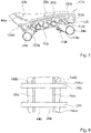
- the Figures 7 to 9 show schematically an aircraft seat device in a second embodiment.
- the aircraft seat device is part of an aircraft seat 10b.
- the aircraft seat 10b is part of a seat row 12b made up of several aircraft seats 10b, 60b, 62b.
- the row of seats 12b has three aircraft seats 10b, 60b, 62b arranged next to one another.
- the aircraft seat 10b is intended to be elevated in an aircraft cabin of an aircraft.
- the aircraft seat 10b includes a stand unit 14b. All aircraft seats 10b, 60b, 62b of the row of seats 12b are elevated via the elevating unit 14b.
- the stand unit 14b is provided to stand the aircraft seat 10b on the cabin floor of the aircraft cabin.
- the stand unit 14b has two crossbeams 24b, 26b.
- the two cross members 24b, 26b are designed as cross tubes.
- the cross members 24b, 26b have an annular cross section.
- the first cross member 24b is designed as a front cross member 24b.
- the front cross member 24b is connected to front seat legs.
- the front seat feet are each rigidly connected to the front cross member 24b.
- the second cross member 26b is designed as a rear cross member 26b.
- the rear cross member 26b is connected to rear seat legs.
- the rear seat feet are each connected rigidly and torsionally to the rear cross member 26b.
- the aircraft seat device includes a seat bottom unit 28b.
- the seat bottom unit 28b is intended to form a seat surface 30b for a passenger. A passenger can sit on the seat surface 30b, which forms the seat bottom unit 28b.
- the aircraft seat device includes a backrest unit 40b.
- the backrest unit 40b is intended to provide a backrest support surface 42b on which a passenger sitting on the aircraft seat 10b can support his back.
- the backrest unit 40b has a base body 44b.
- the base body 44b is formed from a fiber composite material. In this case, the base body 44b has a front wall 48b which is formed from a plurality of fiber composite layers.
- the front wall 48b which forms the base body 44b, is formed from different fiber composite layers, such as in particular CFRP layers and/or GFRP layers.
- the seat bottom unit 28b is partially formed in one piece with the backrest unit 40b.
- the seat bottom unit 28b is from the body 44b, which forms the backrest unit 40b, is formed.
- the seat bottom unit 28b and the backrest unit 40b are formed together by a common base body 44b.
- the common base body 44b forms a supporting shell of the aircraft seat 10b.
- the seat floor unit 28b and the backrest unit 40b are elevated together on a cabin floor of an aircraft cabin via the stand unit 14b.
- the aircraft seat device has a carrier element 52b and a second carrier element 54b, which are assigned to the aircraft seat 10b.
- the two carrier elements 52b, 54b are intended to couple the seat bottom unit 28b and the backrest unit 40b to the stand unit 14b.
- the carrier elements 52b, 54b are arranged below the seat bottom unit 28b.
- the carrier elements 52b, 54b are covered upwards by the seat bottom unit 28b.
- the support elements 52b, 54b do not project laterally beyond the seat bottom unit 28b.
- the carrier elements 52b, 54b are designed as plate-shaped elements. In the carrier elements 52b, 54b there are through-holes which are not described in more detail and are provided to reduce the weight of the carrier elements 52b, 54b.
- the carrier elements 52b, 54b extend over a large part of a seat depth of the seat surface 30b of the seat bottom unit 28b.
- the carrier elements 52b, 54b are arranged spaced apart from one another in the transverse direction.
- the carrier elements 52b, 54b are connected directly to the seat bottom unit 28b.
- the carrier elements 52b, 54b are connected directly to an underside of the base body 44b.
- the carrier elements 52b, 54b are rigidly connected to the base body 44b via an adhesive connection.
- the carrier elements 52b, 54b are additionally firmly connected to the base body 44b via screw connections and/or other form-fitting connections.
- the carrier elements 52b, 54b are laminated onto the base body 44b and/or are overmolded by it. This is particularly conceivable if the base body 44b is formed from a fiber composite material.
- the base body 44b and the carrier elements 52b, 54b are adapted to one another in a form-fitting manner. In this case, a front edge of the base body 44b rests on a projection 142b of the corresponding carrier element 52b, 54b.
- the carrier elements 52b, 54b are slightly upwardly extended in a transition area between the seat bottom unit 28b and the backrest unit 40b and form a lower contour of the base body 44b.
- the base body 44b has a belt attachment recess 146b, 148b on the outer sides of the carrier elements 52b, 54b.
- a safety belt of the aircraft seat 10b is guided through the belt attachment recesses 146b, 148b.
- the safety belt is firmly attached to the rear cross member 26b or to the respective carrier element 52b, 54b via belt attachment elements that are not shown in detail.
- the support elements 52b, 54b are each connected to the front cross member 24b and the rear cross member 26b.
- the carrier elements 52b, 54b are arranged pivotably to the stand unit 14b.
- the support elements 52b, 54b are arranged such that they can be pivoted relative to the rear cross member 26b.
- the carrier elements 52b, 54b are pivotably mounted directly on the rear cross member 26b.
- the support elements 52b, 54b each have a bearing mount 108b.
- the bearing mount 108b is provided to form a plain bearing point. It is fundamentally conceivable that additional lubricants are arranged in the bearing mount 108b.
- the support elements 52b, 54b are mounted so that they can move relative to the front cross member 24b via bearing points 110b.
- the bearing points 110b have two semicircular receptacles 112b, 114b which are spaced apart from one another.
- the two receptacles 112b, 114b are spaced apart from one another via spacer elements 116b.
- the spacer elements 116b are designed as stud screw elements with a head.
- the front cross member 24b abuts the upper receptacle 112b.
- the front cross member 24b rests against the lower receptacle 114b.
- the support elements 52b, 54b each rotate directly about the rear cross member 26b.
- the aircraft seat device has a locking module, which is not shown here in detail, by means of which the seat bottom unit 28b can be locked in the TTL position.
- the carrier elements 52b, 54b can be particularly advantageously adapted to different aircraft seats by adjusting their height.
- the configuration of the support elements 52b, 54b makes it possible, starting from those shown in this exemplary embodiment, to provide support elements with a significantly lower height, which can be used in particular in emergency exit seats in order to to achieve a lower height of the seat bottom unit.
- a lower height of the seat bottom unit could be compensated for by a thicker and removable comfort element.
- the aircraft seat 10b has an armrest 100b.
- the armrest 100b is connected to the backrest unit 40b on a first side of the seat bottom unit 28b.
- the armrest 100b has a base support 150b.
- the base support 150b of the armrest 100b is formed in one piece with the base body 44b of the backrest unit 40b.
- the armrest 100b is at least partially formed onto the base body 44b.
- the base support 150b of the armrest 100b is formed from a fiber composite material. It is conceivable that the base support 150b is formed from the same fiber composite material as the base body 44b.
- the base support 150b of the armrest 100b and the base body 44b are produced together in a lamination process.
- the base support 150b is subsequently connected to the base body 44b via a material connection, for example by gluing, or by a screw connection.
- the armrest 100b has a comfort element that is not shown in detail.
- the comfort element is connected to the base support 150b of the armrest 100b.
- the comfort element forms a support surface for a passenger and is made of a padded material.
- the comfort element is connected to the base support 150b so that it can be separated in a non-destructive manner. As a result, the comfort element can be easily replaced.
- the comfort element is connected to the base support 150b via latching elements that are not shown in detail.
- the comfort element in principle, it is also conceivable for the comfort element to be connected to the base support 150b by means of a materially bonded connection or by other positive and/or non-positive connection elements that appear sensible to the person skilled in the art.
- the armrest 100b is rigidly and immovably connected to the base body 44b.
- the aircraft seat 10b has only the armrest 100b molded onto the base body 44b on one side. In principle, it would be conceivable for the aircraft seat 10b to have a further armrest attached to the base body 44b on the opposite side of the armrest 100b.
- the other aircraft seats 60b, 62b of the row of seats 12b, which are each arranged on one side of the aircraft seat 10b, are designed essentially the same as the aircraft seat 10b.
- the other aircraft seats 60b, 62b each have a base body 152b, 154b, which is identical to the base body 44b of the first aircraft seat 10b.
- the other aircraft seats 60b, 62b each also have only one armrest 138b, 140b formed on them.
- the middle aircraft seat 10b and the outer aircraft seat 60b share the armrest 100b formed by the aircraft seat 10b.
- an armrest (not shown) can be formed via a module connected to the stand unit 14b, in particular the crossbeams 24b, 26b.
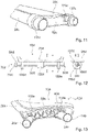
- the figures 10 and 11 show a third embodiment of the aircraft seat device according to the invention.
- the aircraft seat device is part of an aircraft seat 10c.
- the aircraft seat 10c is intended to be elevated in an aircraft cabin of an aircraft.
- the aircraft seat 10c includes a stand unit 14c.
- the stand unit 14c is intended to stand the aircraft seat 10c on the cabin floor of the aircraft cabin.
- the stand unit 14c has two crossbeams 24c, 26c.
- the two cross members 24c, 26c are designed as cross tubes.
- the aircraft seat device includes a seat bottom unit 28c.
- the seat bottom unit 28c is intended to form a seat surface 30c for a passenger. A passenger can sit on the seat surface 30c, which forms the seat bottom unit 28c.
- the aircraft seat device includes a backrest unit 40c.
- the backrest unit 40c is intended to provide a backrest support surface 42c on which a passenger sitting on the aircraft seat 10c can support his back.
- the seat bottom unit 28c and the backrest unit 40c are designed essentially the same as the seat bottom unit and the backrest unit from the previous exemplary embodiments.
- the aircraft seat device has a carrier element 52c and a second carrier element 54c, which are assigned to the aircraft seat 10c.
- the support elements 52c, 54c are directly and rigidly connected to the seat bottom unit 28c of the aircraft seat 10c.
- the support elements 52c, 54c are not designed to be pivotable with respect to the stand unit.
- the seat bottom unit 28c cannot be pivoted between a TTL position and a comfort position.
- the carrier elements 52c, 54c have a receiving hole 118c for connection to the front cross member 24c and a further receiving hole 120c for connection to the rear cross member 26c.
- the aircraft seat device for each support element 52c, 54c has clamp elements 122c, 124c, via which the support elements 52c, 54c are fixed axially on the cross members 24c, 26c.
- the carrier elements 52c, 54c are rigidly fixed on the crossbeams 24c, 26c by the clamp elements 122c, 124c.
- possible belt connection points 172c are shown, which are formed in one piece with the seat bottom unit 28c.
- a safety belt of the aircraft seat 10c could be rigidly connected to the belt connection points 172c.
- a possible belt connection point 170c is shown, which is formed by the carrier element 52c.
- a safety belt of the aircraft seat 10c could be rigidly connected to the belt connection point 170c.
- figure 12 shows a fourth exemplary embodiment of the aircraft seat device according to the invention.
- the aircraft seat device is part of an aircraft seat 10d.
- the aircraft seat 10d is designed essentially the same as the corresponding aircraft seat from the first exemplary embodiment, which is why it will not be described in more detail here.
- the figure 12 represents a strongly abstracted outline of the principle figure 12 a sectional view II is also shown.
- the aircraft seat 10d is intended to be elevated in an aircraft cabin of an aircraft.
- the aircraft seat 10d includes a stand unit, not shown in detail.
- the aircraft seat device has a carrier element 52d and a second carrier element 54d, which are associated with the aircraft seat 10d.
- the carrier elements 52d, 54d are rigidly connected to the stand unit.
- the aircraft seat 10c includes a seat bottom unit 28d and a backrest unit not shown in detail.
- the seat bottom unit 28d and the backrest unit are pivotable to the support elements 52d, 54d.
- the aircraft seat device has a bearing module 76d for the pivotable mounting of the seat bottom unit 28d and the backrest unit.
- the bearing module 76d is designed as a pivot bearing.
- the bearing module 76d forms a pivot axis 78d, via which the seat bottom unit 28d and the backrest unit can be pivoted to the stand unit.
- the pivot axis 78d is arranged below the seat bottom unit 28d.
- the pivot axis 78d of the storage module 76d is aligned coaxially to a transverse direction of the stand unit.
- the bearing module 76d includes a torsion element 80d.
- the torsion element 80d is designed as a torsion bar.
- the torsion element 80d designed as a torsion bar forms the pivot axis 78d.
- the torsion element 80d designed as a torsion bar is provided to be twisted about the pivot axis 78d when the seat base unit 28d is pivoted.
- the torsion element 80d designed as a torsion bar which is shown in a cross section in the sectional view II, has a cruciform cross section.
- the torsion element 80d designed as a torsion bar has a different cross section that appears sensible to a person skilled in the art, as a result of which the torsion element 80d has rigid and torsionally flexible properties.
- the torsion element 80d is firmly connected at both of its ends to the carrier elements 52d, 54d.
- the torsion element 80d is connected non-rotatably to the carrier elements 52d, 54d by fastening elements that are not shown in detail.
- the torsion element 80d is connected to the carrier elements 52d, 54d via a fixed bearing.
- the torsion element 80d is connected centrally to the seat bottom unit 28d.
- the torsion element 80d is connected centrally in the transverse direction to an underside of the seat bottom unit 28d.
- the bearing module has a bearing element 156d for connection to the seat bottom unit 28d.
- the bearing element 156d is rigidly connected to the seat bottom unit 28d via suitable fastening elements. In principle, it is also conceivable for the bearing element 156d to be formed in one piece with the seat bottom unit 28d or to be connected to the seat bottom unit 28d via a material connection.
- the bearing element 156d is designed as a fixed bearing.
- the torsion element 80d is mounted in a torsion-proof manner in the bearing element 156d.
- the bearing module 76d has two further bearing elements 158d, 160d.
- the other bearing elements 158d, 160d are also attached to the underside of the seat bottom unit 28d.
- the bearing elements 158d, 160d are rigidly connected to the seat bottom unit 28d via suitable fastening elements.
- the two other bearing elements 158d, 160d are designed as floating bearings.
- the torsion element 80d is guided in the bearing elements 158d, 160d designed as floating bearings.
- the torsion element 80d can twist in the bearing elements 158d, 160d.
- the bearing elements 158d, 160d are each arranged on a side of the seat bottom unit 28d facing a carrier element 52d, 54d.
- the storage module 76d has four stops 166d, 168d.
- the stops 166d, 168d are provided to prevent a rotation of the torsion element 80d and thereby a pivoting of the seat bottom unit 28d and of the backrest unit 40d. If the torsion element 80d strikes the stops 166d, 168d, the aircraft seat 10d is in its comfort position.
- the stops 166d, 168d are arranged in the bearing elements 158d, 160d designed as floating bearings.
- the stops 166d, 168d are formed as elevations on an inside of bearing recesses in the respective bearing element 158d, 160d. In principle, it is also conceivable that the bearing elements 158d, 160d each form only one stop 166d, 168d or more stops 166d, 168d.
- the torsion element 80d designed as a torsion bar is in a neutral position. In the neutral position, the torsion element 80d is not twisted. If the seat bottom unit 28d is pivoted into a comfort position, the torsion element 80d is carried along via the bearing element 156d connected to the seat bottom unit 28d. Since the torsion element 80d is mounted in a rotationally fixed manner via fixed bearings with the carrier elements 52d, 54d arranged rigidly with respect to the stand unit, the torsion element 80d is twisted in itself when pivoted into the comfort position.
- the aircraft seat device has a locking module that is not shown in detail.
- the locking module is provided to lock the seat bottom assembly 28d and the backrest assembly in a TTL position. In principle, it is also conceivable that the aircraft seat device does not have a locking module and that the seat bottom unit 28d is sufficiently secured in the TTL position by the torsional rigidity of the torsion element 80d.
- the figure 13 shows schematically an aircraft seat device in a fifth embodiment.
- the aircraft seat device is part of an aircraft seat 10e.
- the aircraft seat 10e is part of a seat row 12e made up of several aircraft seats 10e.
- the row of seats 12e has three aircraft seats 10e arranged next to one another.
- the aircraft seat 10e is intended to be elevated in an aircraft cabin of an aircraft.
- the aircraft seat 10e includes a stand unit 14e. All aircraft seats 10e of the seat row 12e are elevated via the stand unit 14e.
- the stand unit 14e has two crossbeams 24e, 26e.
- the two cross members 24e, 26e are designed as cross tubes.
- the aircraft seat device includes a seat bottom unit 28e.
- the seat bottom unit 28e is provided to form a seat surface 30e for a passenger.
- the aircraft seat device includes a backrest unit 40e.
- the aircraft seat 10e and in particular the seat bottom unit 28e and the backrest unit 40e are identical to the second embodiment of FIG Figures 7 to 9 educated.
- the aircraft seats of the seat row 12e which are not shown in detail here, are also designed identically to the second exemplary embodiment.
- the aircraft seats 10e of the seat row 12e are connected rigidly and not pivotably to the stand unit 14e.
- the aircraft seats 10e can only represent one seating position.
- the aircraft seats 10e of the row of seats are always aligned in a TTL position.
- the aircraft seat device has a first support element 52e and a second support element, not shown in detail, which are assigned to the aircraft seat 10e.
- the two carrier elements 52e are intended to couple the seat bottom unit 28e and the backrest unit 40e to the stand unit 14e.
- the carrier elements 52e are rigidly coupled to the stand unit 14e.
- the carrier elements 52e are each connected to the front cross member 24e and the rear cross member 26e.
- the support elements 52e are mounted directly on the rear cross member 26e.
- the carrier elements 52e each have a bearing mount 108e.
- the bearing mount 108e is provided to form a fixed bearing.
- the support elements 52e are mounted rigidly with respect to the front cross member 24e via bearing points 110e.
- the bearing mounts 110e are provided to form a fixed bearing.
- the support elements 52e are connected rigidly and immovably to the crossbeams 24e, 26e by the bearing mounts 108e, 110e.
- the carrier elements 52e are fixed axially on the crossbeams 24e, 26e via the bearing mounts 108e, 110e.
Landscapes
- Engineering & Computer Science (AREA)
- Aviation & Aerospace Engineering (AREA)
- Transportation (AREA)
- Mechanical Engineering (AREA)
- Seats For Vehicles (AREA)
Description
- Die Erfindung betrifft einen Flugzeugsitz mit einer Armlehne und mit einer Flugzeugsitzvorrichtung nach dem Oberbegriff des Patentanspruchs 1.
- Es sind bereits Flugzeugsitze vorgeschlagen worden.
- Die Aufgabe der Erfindung besteht insbesondere darin, einen gattungsgemäßen Flugzeugsitz mit verbesserten Eigenschaften hinsichtlich eines Gewichts und eines Komforts bereitzustellen. Die Aufgabe wird erfindungsgemäß durch die Merkmale des
- Patentanspruchs 1 gelöst, während vorteilhafte Ausgestaltungen und Weiterbildungen der Erfindung den Unteransprüchen entnommen werden können.
- Die Dokumente
US 2012/139302 A1 ,US 6 402 244 B1 ,US 2011/148167 A1 undUS 3 224 808 A zeigen bekannt Flugzeugsitze.GB 2 437 164 A - Die Erfindung ist in Anspruch 1 definiert. Vorteilhafte Ausgestaltungen sind in den Unteransprüchen beschrieben. Die folgenden Absätze nennen Vorschläge welche für das Verständnis der Erfindung sinnvoll erscheinen, der Gegenstand und Schutzumfang der Erfindung wird jedoch allein durch die Ansprüche definiert.
- Erfindungsgemäß wird ein Flugzeugsitz mit unter Anderem, einer Flugzeugsitzvorrichtung mit zumindest einer Sitzbodeneinheit, die zumindest teilweise eine Sitzfläche ausbildet, mit einer Aufständereinheit, die dazu vorgesehen ist, auf einer Aufständerebene aufgeständert zu werden, und mit zumindest einem Trägerelement, welches sich zumindest über einen Großteil einer Sitztiefe der Sitzfläche erstreckt und dazu vorgesehen ist, die Sitzbodeneinheit mit der Aufständereinheit zu koppeln, vorgeschlagen. Unter einer "Flugzeugsitzvorrichtung" soll dabei insbesondere eine Vorrichtung verstanden werden, die wenigstens einen Teil oder einen gesamten Flugzeugsitz ausbildet. Unter einem "Flugzeugsitz" soll dabei insbesondere ein Sitz verstanden werden, der in einer Flugzeugkabine eines Flugzeugs aufgeständert ist. Ein Flugzeugsitz weist dabei vorzugsweise zumindest eine Sitzbodeneinheit, eine Rückenlehneneinheit, eine Aufständereinheit und/oder zumindest eine Armlehneneinheit auf. Dabei ist der Flugzeugsitz vorzugsweise als Teil von mehreren nebeneinander angeordneten Flugzeugsitzen ausgebildet. Unter einer "Sitzbodeneinheit" soll dabei insbesondere eine Einheit verstanden werden, die den Sitzbereich für einen Passagier ausbildet, wobei die Sitzbodeneinheit dabei vorzugsweise von einem Grundkörper und einem auf dem Grundkörper angebrachten Polster gebildet ist. Unter einem "Sitzbereich" soll dabei insbesondere ein Bereich des Sitzes verstanden werden, der dazu vorgesehen ist, dass ein Passagier, insbesondere während eines Transports, beispielsweise während eines Flugs, darauf sitzt. Der Grundkörper der Sitzbodeneinheit ist dabei vorzugsweise aus einem Faserverbundwerkstoff hergestellt. Unter einer "Aufständereinheit" soll dabei insbesondere eine Einheit verstanden werden, mittels der ein Flugzeugsitz auf einer Aufständerebene der Flugzeugkabine aufgeständert ist. Die Aufständereinheit weist dabei vorzugsweise zumindest einen vorderen Sitzfuß, einen hinteren Sitzfuß sowie mit den Sitzfüßen gekoppelte Querträger auf, die in einer Querrichtung des Flugzeugsitzes verlaufen. Grundsätzlich ist es dabei auch denkbar, dass die Aufständereinheit lediglich einen einzelnen Querträger aufweist. Unter einem "Trägerelement" soll dabei insbesondere ein Element verstanden werden, über das Kräfte aus der Sitzbodeneinheit und/oder der Rückenlehneneinheit in die Aufständereinheit des Flugzeugsitzes abgeleitet werden können. Dabei ist ein Trägerelement insbesondere aus einem steifen Material gebildet und ist dabei sowohl mit einem vorderen Querträger als auch einem hinteren Querträger der Aufständereinheit gekoppelt. Dabei ist das Trägerelement vorzugsweise drehfest und axial fixiert mit den Querträgern verbunden. Dazu ist das wenigstens eine Trägerelement über eine Form- und/oder Kraftschlussverbindung fest mit den Querträgern verbindbar. Grundsätzlich ist es auch denkbar, dass das zumindest eine Trägerelement stoffschlüssig mit den Querträgern verbunden ist. Vorzugsweise weist ein Flugzeugsitz zwei Trägerelemente auf, über die die Sitzbodeneinheit des Flugzeugsitzes mit der Aufständereinheit gekoppelt ist. Ist der Flugzeugsitz als Teil einer Sitzreihe mit mehreren Flugzeugsitzen ausgebildet, ist es vorteilhaft denkbar, dass ein Trägerelement, das zwischen zwei benachbarten Flugzeugsitzen angeordnet ist, zur Anbindung zumindest der Sitzbodeneinheiten beider Flugzeugsitze vorgesehen ist. Unter einer "Sitztiefe der Sitzfläche" soll dabei insbesondere eine Erstreckung der Sitzbodeneinheit in einer Sitzrichtung der Sitzbodeneinheit verstanden werden. Die Sitztiefe ist dabei von einem vorderen Ende der Sitzbodeneinheit, die ein vorderes Ende des Flugzeugsitzes ausbildet, bis an ein hinteres Ende, an dem die Sitzbodeneinheit mit der Rückenlehneneinheit gekoppelt ist, gemessen. Unter einem "Großteil der Sitztiefe" soll dabei insbesondere zumindest über 50% der gesamten Sitztiefe, vorzugsweise zumindest 75% der gesamten Sitztiefe und in einer besonders vorteilhaften Ausgestaltung mehr als 90% der gesamten Sitztiefe verstanden werden. Unter einer "Rückenlehneneinheit" soll dabei insbesondere eine Einheit des Flugzeugsitzes verstanden werden, die eine Rückenlehnenauflagefläche ausbildet, an der ein auf dem Flugzeugsitz sitzender Passagier seinen Rücken anlehnen kann. Dabei umfasst die Rückenlehneneinheit vorzugsweise zumindest einen Grundkörper und ein Polsterelement, welches die Rückenlehnenauflagefläche ausbildet. Die Rückenlehneneinheit ist dabei an einem hinteren Ende einer Sitzbodeneinheit angeordnet und erstreckt sich von der Sitzbodeneinheit nach oben, von einer Aufständereinheit weg. Der Grundkörper der Rückenlehneneinheit ist dabei vorzugsweise aus einem Faserverbundwerkstoff gebildet. Dabei ist es denkbar, dass der Grundkörper der Rückenlehneneinheit und der Grundkörper der Sitzbodeneinheit einstückig miteinander ausgebildet sind. Unter "vorgesehen" soll insbesondere speziell ausgelegt und/oder ausgestattet verstanden werden. Darunter, dass ein Objekt zu einer bestimmten Funktion vorgesehen ist, soll insbesondere verstanden werden, dass das Objekt diese bestimmte Funktion in zumindest einem Anwendungs- und/oder Betriebszustand erfüllt und/oder ausführt. Durch eine erfindungsgemäße Ausgestaltung kann vorteilhaft ein Flugzeugsitz bereitgestellt werden, der besonders leicht und kostengünstig hergestellt werden kann.
- Weiter wird vorgeschlagen, dass das wenigstens eine Trägerelement in wenigstens einer Sitzposition zumindest im Wesentlichen unterhalb einer Oberkante der Sitzbodeneinheit angeordnet ist. Unter einer "Sitzposition" soll dabei insbesondere eine Stellung des Flugzeugsitzes verstanden werden, in der der Flugzeugsitz voll montiert ist und ein Passagier auf der Sitzbodeneinheit des Flugzeugsitzes sitzen kann. Unter einer "Oberkante der Sitzbodeneinheit" soll dabei insbesondere eine Kante der Sitzbodeneinheit verstanden werden, die einen größten Abstand von einer Aufständerebene aufweist, auf der der Flugzeugsitz, dessen Teil die Sitzbodeneinheit ist, aufgeständert ist. Dabei soll unter einer Oberkante der Sitzbodeneinheit insbesondere eine vordere Kante der Sitzbodeneinheit, insbesondere eines Sitzpolsters, verstanden werden. Dabei ist die Trägereinheit insbesondere in einer TTL-Position des Flugzeugsitzes unterhalb der Oberkante der Sitzbodeneinheit angeordnet. Dadurch kann der Flugzeugsitz besonders vorteilhaft kompakt ausgebildet werden.
- Weiter wird vorgeschlagen, dass die Flugzeugsitzvorrichtung eine Rückenlehneneinheit aufweist, die zumindest teilweise einstückig mit der Sitzbodeneinheit ausgebildet ist. Unter "zumindest teilweise einstückig" soll dabei insbesondere verstanden werden, dass zumindest Teile der Rückenlehneneinheit und der Sitzbodeneinheit aus einem gleichen Bauteil gebildet sind und insbesondere zusammen aus zumindest einer Faserverbundlage gebildet sind. Dadurch kann eine besonders vorteilhafte Sitzvorrichtung bereitgestellt werden.
- Ferner wird vorgeschlagen, dass das wenigstens eine Trägerelement in wenigstens einer Sitzposition von der Sitzbodeneinheit nach oben abgedeckt ist. Unter "nach oben abgedeckt" soll dabei insbesondere verstanden werden, dass die Trägerelemente direkt unterhalb der Sitzbodeneinheit angeordnet sind und nicht seitlich über die Sitzbodeneinheit hinausragen. Dadurch kann das wenigstens eine Trägerelement vorteilhaft platzsparend an dem Flugzeugsitz untergebracht werden.
- Es wird weiterhin vorgeschlagen, dass die Sitzbodeneinheit und/oder eine Rückenlehneneinheit dazu vorgesehen sind, schwenkbar mit der Aufständereinheit verbunden zu sein. Dabei sind die Sitzbodeneinheit und die Rückenlehneneinheit um einen gemeinsamen Drehpunkt gelagert. Unter "schwenkbar mit der Aufständereinheit verbunden" soll dabei insbesondere verstanden werden, dass Elemente, wie insbesondere die Sitzbodeneinheit und/oder die Rückenlehneneinheit, zumindest zu einem Teil der Aufständereinheit schwenkbar gelagert sind. Unter "schwenkbar gelagert" soll dabei insbesondere um eine Schwenkachse um einen definierten Schwenkwinkel zueinander rotierbar gelagert verstanden werden. Dadurch kann vorteilhaft einfach ein Recline für den Flugzeugsitz bereitgestellt werden.
- Des Weiteren wird vorgeschlagen, dass die Sitzbodeneinheit und/oder eine Rückenlehneneinheit dazu vorgesehen sind, an dem wenigstens einen Trägerelement schwenkbar gelagert zu sein. Unter "an dem Trägerelement schwenkbar gelagert" soll dabei insbesondere verstanden werden, dass die Sitzbodeneinheit und/oder die Rückenlehneneinheit über ein geeignetes Lagermodul direkt mit dem zumindest einen Trägerelement verbunden werden. Dadurch kann die Sitzbodeneinheit und/oder die Rückenlehneneinheit für eine Bereitstellung einer Reclinefunktion des Flugzeugsitzes besonders einfach ausgeführt werden.
- Außerdem wird vorgeschlagen, dass die Flugzeugsitzvorrichtung wenigstens ein Lagermodul aufweist, das dazu vorgesehen ist, die Sitzbodeneinheit und/oder die Rückenlehneneinheit zu den Sitzteilern zu verschwenken und dazu eine Schwenkachse ausbildet, die unterhalb der Sitzbodeneinheit angeordnet ist. Unter einem "Lagermodul" soll dabei insbesondere ein Modul verstanden werden, über das zumindest zwei Elemente, wie insbesondere die Sitzbodeneinheit und/oder die Rückenlehneneinheit, zu dem wenigstens einen Lagermodul beweglich, insbesondere verschwenkbar lagern. Dabei ist das Lagermodul vorzugsweise als ein Gleitlager ausgebildet. Grundsätzlich ist es auch denkbar, dass das Lagermodul ein oder mehrere Wälzlager aufweist, über die die Elemente schwenkbar zueinander ausgebildet sind. Grundsätzlich ist es ebenso denkbar, dass die Sitzbodeneinheit und/oder die Rückenlehneneinheit über einen fixierten biegesteifen, aber drehweichen Torsionsstab schwenkbar gelagert sind, wobei der Torsionsstab durch ein Verwinden die Verschwenkung bewirkt. Dadurch kann die Reclinefunktion des Flugzeugsitzes besonders vorteilhaft ausgestaltet werden.
- Es wird weiter vorgeschlagen, dass die Schwenkachse des Lagermoduls, koaxial zu einer Querrichtung der Aufständereinheit ausgerichtet ist. Unter einer "Schwenkachse des Lagermoduls" soll dabei insbesondere eine Achse verstanden werden, um die die über das Lagermodul zueinander schwenkbar gelagerten Elemente, wie insbesondere das wenigstens eine Trägerelement und die Sitzbodeneinheit und/oder die Rückenlehneneinheit, zueinander schwenkbar sind. Unter einer Querrichtung der Aufständereinheit soll dabei insbesondere eine Richtung verstanden werden, die parallel zu den Querträgern der Aufständereinheit verläuft. Die Querrichtung ist dabei vorzugsweise orthogonal sowohl zu der Sitzrichtung, als auch zu einer senkrecht auf der Aufständerebene stehenden Vertikalrichtung ausgerichtet. Dadurch kann das Lagermodul besonders vorteilhaft ausgebildet werden.
- Zudem wird vorgeschlagen, dass das Lagermodul zumindest ein Torsionselement aufweist, das die Schwenkachse des Sitzes ausbildet und sich über eine Sitzbreite der Sitzbodeneinheit erstreckt. Unter einem "Torsionselement" soll dabei insbesondere ein Element verstanden werden, das dazu vorgesehen ist, Torsionsmomente weiterzuleiten, um insbesondere eine Bewegung von einem einen Ende an ein anderes Ende zu übertragen. Dabei ist das Torsionselement vorzugsweise als ein Torsionsrohr oder ein Torsionselement ausgebildet. Unter einem "Torsionsstab" soll dabei insbesondere ein biegesteifer, aber verdrehweicher Stab verstanden werden, der dazu vorgesehen ist, bei einer Torsionsbelastung zumindest um einen gewissen Winkel elastisch verwunden zu werden. Unter einem "Torsionsrohr" soll dabei ein im Wesentlichen torsionssteifes Rohr verstanden werden, das sich bei einer Torsionsbelastung im Wesentlichen nicht verwindet und ein Torsionsmoment im Wesentlichen ungemindert weitergibt. Dadurch kann das Lagermodul besonders vorteilhaft ausgestaltet werden.
- Weiter wird vorgeschlagen, dass die Flugzeugsitzvorrichtung zumindest ein Verriegelungsmodul aufweist, welches zumindest in einer Sitzstellung dazu vorgesehen ist, die Sitzbodeneinheit und/oder Rückenlehneneinheit zu verriegeln. Unter einem "Verriegelungsmodul" soll dabei insbesondere ein Modul verstanden werden, das zwei Elemente zumindest in einem Betriebszustand zueinander fixiert. Dabei ist das Verriegelungsmodul insbesondere dazu vorgesehen, die Sitzbodeneinheit und/oder die Rückenlehneneinheit in zumindest einer Sitzstellung zu der Aufständereinheit zu fixieren. Dadurch kann die Sitzbodeneinheit und/oder die Rückenlehneneinheit in zumindest einer Sitzstellung fixiert werden. Unter "verriegeln" soll dabei insbesondere in einer Position fest fixieren verstanden werden. Unter einer Sitzstellung soll dabei insbesondere eine Ausrichtung der Sitzbodeneinheit und/oder der Rückenlehneneinheit zu der Aufständerebene verstanden werden. Dabei weist der Flugzeugsitz zumindest eine als TTL-Position und eine als Komfortposition ausgebildete Sitzstellung auf. Die TTL-Position ist dabei als eine Stellung des Flugzeugsitzes ausgebildet, die in einer Start-, Lande- und Turbulenzphase eines Flugs eingenommen werden muss. Die TTL-Position ist als eine Taxi-, Takeoff- oder Landing-Position ausgebildet. Dabei ist die TTL-Position als eine aufrechte Sitzstellung ausgebildet, in der der Sitzbereich der Sitzbodeneinheit im Wesentlichen parallel zu der Aufständerebene und die Rückenlehnenfläche der Rückenlehneneinheit im Wesentlichen orthogonal zu der Aufständerebene ausgerichtet ist. Dadurch kann der Flugzeugsitz in zumindest einer Sitzstellung vorteilhaft verriegelt werden.
- Ferner wird vorgeschlagen, dass das Verriegelungsmodul wenigstens ein Verriegelungselement aufweist, das die Sitzbodeneinheit lediglich in einer als TTL-Position ausgebildeten Sitzstellung verriegelt. Dadurch kann ein vorteilhaft einfaches Verriegelungsmodul bereitgestellt werden und der Flugzeugsitz insbesondere in der TTL-Position vorteilhaft gesichert werden.
- Es wird weiterhin vorgeschlagen, dass die Flugzeugsitzvorrichtung ein Lagermodul aufweist, das das wenigstens eine Trägerelement direkt mit einem hinteren Querträger schwenkbar koppelt. Unter "direkt koppeln" soll dabei insbesondere verstanden werden, dass eine Lagerung des Trägerelements unmittelbar auf dem Querträger erfolgt. Dadurch kann eine vorteilhaft einfache Flugzeugsitzvorrichtung erreicht werden.
- Weitere Vorteile ergeben sich aus der folgenden Zeichnungsbeschreibung. In den Zeichnungen sind fünf Ausführungsbeispiele der Erfindung dargestellt. Die Zeichnungen, die Beschreibung und die Ansprüche enthalten zahlreiche Merkmale in Kombination. Der Fachmann wird die Merkmale zweckmäßigerweise auch einzeln betrachten und zu sinnvollen weiteren Kombinationen zusammenfassen.
- Es zeigen:
- Fig. 1
- eine schematische Darstellung einer erfindungsgemäßen Flugzeugsitzvorrichtung in einem ersten Ausführungsbeispiel mit einer Sitzreihe,
- Fig. 2
- eine schematische Seitenansicht der erfindungsgemäßen Flugzeugsitzvorrichtung mit einem Flugzeugsitz in einer TTL-Position und einer angedeuteten Komfortposition,
- Fig. 3
- eine Detailansicht der Flugzeugsitzvorrichtung, insbesondere eines Trägerelements und einer Sitzbodeneinheit,
- Fig. 4
- eine Detailansicht einer Verriegelungseinheit,
- Fig. 5
- eine schematische Schnittansicht durch eine Sitzbodeneinheit,
- Fig. 6
- eine schematische Darstellung einer Sitzbodeneinheit und einer Rückenlehneneinheit mit möglichen Schwenkpunkten,
- Fig. 7
- eine schematische Darstellung einer erfindungsgemäßen Flugzeugsitzvorrichtung in einem zweiten Ausführungsbeispiel,
- Fig. 8
- eine schematische Darstellung der Sitzbodeneinheit und Teilen einer Aufständereinheit von unten,
- Fig. 9
- eine schematische Darstellung der Flugzeugsitzvorrichtung im zweiten Ausführungsbeispiel mit einer Sitzreihe mit drei Flugzeugsitzen,
- Fig. 10
- eine schematische Darstellung einer erfindungsgemäßen Flugzeugsitzvorrichtung in einem dritten Ausführungsbeispiel,
- Fig. 11
- eine schematische Darstellung eines Teils einer Aufständereinheit und eines Trägerelements,
- Fig. 12
- eine stark schematisierte Schnittdarstellung einer Flugzeugsitzvorrichtung in einem vierten Ausführungsbeispiel mit einer Sitzbodeneinheit und einem als Torsionsstab ausgebildeten Torsionselement und
- Fig. 13
- eine schematische Darstellung einer erfindungsgemäßen Flugzeugsitzvorrichtung in einem fünften Ausführungsbeispiel.
- Die
Figuren 1 bis 6 zeigen ein erstes Ausführungsbeispiel eines erfindungsgemäßen Flugzeugsitzes. - Die Flugzeugsitzvorrichtung ist Teil eines Flugzeugsitzes 10a. Der Flugzeugsitz 10a ist dazu vorgesehen, in einer Flugzeugkabine eines Flugzeugs aufgeständert zu werden. Ein Kabinenboden der Flugzeugkabine bildet dabei eine Aufständerebene aus, auf der der Flugzeugsitz 10a aufgeständert ist. Der Flugzeugsitz 10a ist dabei Teil einer Sitzreihe 12a aus mehreren Flugzeugsitzen 10a, 60a, 62a. Die Sitzreihe 12a weist drei nebeneinander angeordnete Flugzeugsitze 10a, 60a, 62a auf. Grundsätzlich ist es auch denkbar, dass die Sitzreihe 12a eine andere Anzahl an Flugzeugsitzen 10a, 60a, 62a aufweist. In der Flugzeugkabine sind mehrere, nicht näher dargestellte Sitzreihen mit der erfindungsgemäßen Flugzeugsitzvorrichtung angeordnet. Die weiteren Sitzreihen sind dabei in einem nicht näher dargestellten und beschriebenen Layout in der Passagierkabine angeordnet, vorzugsweise aber parallel hintereinander. Der Flugzeugsitz 10a umfasst eine Aufständereinheit 14a. Die Aufständereinheit 14a ist dazu vorgesehen, den Flugzeugsitz 10a auf dem Kabinenboden der Flugzeugkabine aufzuständern. Die Aufständereinheit 14a umfasst zwei vordere Sitzfüße 16a, 18a sowie zwei hintere Sitzfüße 20a, 22a. Die Sitzfüße 16a, 18a, 20a, 22a sind an ihrem unteren Ende jeweils über nicht näher dargestellte Anbindungselemente fest mit nicht näher dargestellten Führungsschienen der Flugzeugkabine gekoppelt. Die Führungsschienen sind dabei vorzugsweise in den Kabinenboden eingelassen. Die Aufständereinheit 14a weist zwei Querträger 24a, 26a auf. Die zwei Querträger 24a, 26a sind als Querrohre ausgebildet. Die Querträger 24a, 26a weisen einen ringförmigen Querschnitt auf. Der erste Querträger 24a ist dabei als ein vorderer Querträger 24a ausgebildet. Der vordere Querträger 24a ist mit den vorderen Sitzfüßen 16a, 18a verbunden. Dabei sind die vorderen Sitzfüße 16a, 18a jeweils starr mit dem vorderen Querträger 24a verbunden. Der zweite Querträger 26a ist als ein hinterer Querträger 26a ausgebildet. Der hintere Querträger 26a ist mit den hinteren Sitzfüßen 20a, 22a verbunden. Dabei sind die hinteren Sitzfüße 20a, 22a jeweils starr und verdrehsicher mit dem hinteren Querträger 26a verbunden. Die Sitzfüße 16a, 18a, 20a, 22a sind jeweils über nicht näher beschriebene Koppelstellen kraft-, form- und/oder stoffschlüssig mit dem entsprechenden Querträger 24a, 26a verbunden. Die Querträger 24a, 26a erstrecken sich in einer Querrichtung der Flugzeugsitze 10a der Sitzreihe 12a. Dabei erstrecken sich die Querträger 24a, 26a über die gesamte Breite der Sitzreihe 12a. An einem gangseitigen Ende der Sitzreihe 12a weist die Flugzeugsitzvorrichtung ein Trittelement 164a auf. Das Trittelement 164a ist als ein Stewardstep ausgebildet. Das Trittelement 164a bildet dabei einen erhöhten Tritt für eine Person aus. Das Trittelement 164a ist dabei mit der Aufständereinheit 14a verbunden. Dabei ist das Trittelement 164a auf den Querträgern 24a, 26a aufgesteckt. Das Trittelement 164a ist aus einem Metall gebildet, wie insbesondere einem Aluminium. Grundsätzlich ist es auch denkbar, dass das Trittelement 164a aus einem Faserverbundwerkstoff gebildet ist.
- Die Flugzeugsitzvorrichtung umfasst eine Sitzbodeneinheit 28a. Die Sitzbodeneinheit 28a ist dazu vorgesehen, eine Sitzfläche 30a für einen Passagier auszubilden. Auf der Sitzfläche 30a, den die Sitzbodeneinheit 28a ausbildet, kann ein Passagier sitzen. Die Sitzbodeneinheit 28a ist dabei mit der Aufständereinheit 14a verbunden. Die Sitzbodeneinheit 28a umfasst einen Grundkörper 32a. Der Grundkörper 32a der Sitzbodeneinheit 28a weist eine dünnwandige Rückwand 34a auf. Die dünnwandige Rückwand 34a ist aus einem Faserverbundwerkstoff gebildet. Dabei ist die Rückwand 34a von einer geformten CFK-Platte gebildet. Grundsätzlich ist es auch denkbar, dass die Rückwand 34a aus einem anderen, dem Fachmann als sinnvoll erscheinenden Faserverbundwerkstoff gebildet ist. Die dünnwandige Rückwand 34a schließt die Sitzbodeneinheit 28a nach unten hin ab. Die dünnwandige Rückwand 34a des Grundkörpers 32a der Sitzbodeneinheit 28a ist dabei der unter der Sitzbodeneinheit 28a angeordneten Aufständereinheit 14a zugewandt. Die Sitzbodeneinheit 28a umfasst eine dünnwandige Frontwand 36a. Die dünnwandige Frontwand 36a ist mit der dünnwandigen Rückwand 34a der Sitzbodeneinheit 28a verbunden. Die dünnwandige Frontwand 36a ist aus einem Faserverbundwerkstoff gebildet. Die dünnwandige Frontwand 36a ist dabei aus einem gleichen Material gebildet wie die dünnwandige Rückwand 34a. Die dünnwandige Frontwand 36a ist an einer Oberseite der Sitzbodeneinheit 28a angeordnet. Die dünnwandige Frontwand 36a der Sitzbodeneinheit 28a ist nach oben ausgerichtet. Die dünnwandige Frontwand 36a der Sitzbodeneinheit 28a bildet die Sitzfläche 30a aus. Die dünnwandige Rückwand 34a und die dünnwandige Frontwand 36a der Sitzbodeneinheit 28a sind miteinander verbunden. Dabei sind die dünnwandige Frontwand 36a und die dünnwandige Rückwand 34a stoffschlüssig miteinander verbunden. Die Sitzbodeneinheit 28a umfasst ein nicht näher dargestelltes Versteifungselement, das zur Versteifung der Sitzbodeneinheit 28a vorgesehen ist. Dazu ist das Versteifungselement zwischen der dünnwandigen Rückwand 34a und der dünnwandigen Frontwand 36a der Sitzbodeneinheit 28a angeordnet. Das Versteifungselement ist als ein Schaumkern ausgebildet. Grundsätzlich ist es auch denkbar, dass die Sitzbodeneinheit 28a kein oder ein anders ausgebildetes Versteifungselement aufweist. Die dünnwandige Frontwand 36a und/oder die dünnwandige Rückwand 34a können dabei grundsätzlich auch aus vorgefertigten Organosheets gebildet sein. Unter Organosheets sind dabei Fasermatrix-Halbzeuge zu verstehen, die in einer Kunststoffmatrix voreingelegte Verstärkungsfasern aufweisen. Die Sitzbodeneinheit 28a umfasst ein Komfortelement 38a. Das Komfortelement 38a ist zur Ausbildung der Sitzfläche 30a vorgesehen. Dazu ist das Komfortelement 38a auf einer nach oben gerichteten Außenseite der dünnwandigen Frontwand 36a der Sitzbodeneinheit 28a fest angebunden. Das Komfortelement 38a ist dabei von einem Polster und einem mit dem Polster lösbar verbundenen Bezug gebildet. Dabei ist das Komfortelement 38a über nicht näher dargestellte Verbindungselemente mit der dünnwandigen Frontwand 36a verbunden.
- Die Flugzeugsitzvorrichtung umfasst eine Rückenlehneneinheit 40a. Die Rückenlehneneinheit 40a ist dazu vorgesehen, eine Rückenlehnenauflagefläche 42a bereitzustellen, an der sich ein auf dem Flugzeugsitz 10a sitzender Passagier mit seinem Rücken abstützen kann. Die Rückenlehneneinheit 40a ist dabei an einem hinteren Ende des Flugzeugsitzes 10a angeordnet. Die Rückenlehneneinheit 40a ist dabei an einem hinteren Ende der Sitzbodeneinheit 28a angeordnet. Die Rückenlehneneinheit 40a umfasst einen Grundkörper 44a. Der Grundkörper 44a umfasst eine dünnwandige Rückwand 46a. Die dünnwandige Rückwand 46a ist aus einem Faserverbundwerkstoff gebildet. Dabei ist die Rückwand 46a von einer geformten CFK-Platte gebildet. Grundsätzlich ist es auch denkbar, dass die Rückwand 46a aus einem anderen, dem Fachmann als sinnvoll erscheinenden Faserverbundwerkstoff gebildet ist. Die dünnwandige Rückwand 46a schließt die Rückenlehneneinheit 40a nach hinten hin ab. Die Rückwand 46a der Rückenlehneneinheit 40a ist dabei dem hinter der Flugzeugsitzvorrichtung angeordneten Bereich, in dem vorzugsweise eine weitere Sitzreihe angeordnet ist, zugewandt. Die Rückwand 46a ist auf einer Außenseite, die nach hinten von dem Flugzeugsitz 10a weggerichtet ist, mit einer nicht näher dargestellten oder bezeichneten Beschichtung beschichtet. Die Beschichtung ist dazu vorgesehen, dass die Außenseite der Rückwand 46a kratzfest ausgebildet ist. Die dünnwandige Rückwand 46a ist als ein sichtbares Designelement ausgebildet. Dazu ist die als sichtbares Designelement ausgebildete dünnwandige Rückwand 46a in einem komplett montierten Zustand des Flugzeugsitzes 10a insbesondere von hinten zu sehen. Dabei schließt die als sichtbares Designelement ausgebildete dünnwandige Rückwand 46a die Rückenlehneneinheit 40a nach hinten ab. Der Grundkörper 44a der Rückenlehneneinheit 40a umfasst eine dünnwandige Frontwand 48a. Die dünnwandige Frontwand 48a ist mit der dünnwandigen Rückwand 46a verbunden. Die dünnwandige Frontwand 48a ist aus einem Faserverbundwerkstoff gebildet. Die dünnwandige Frontwand 48a ist dabei im Wesentlichen aus einem gleichen Material gebildet wie die dünnwandige Rückwand 46a. Die dünnwandige Frontwand 48a ist an einer Vorderseite der Rückenlehneneinheit 40a angeordnet. In einer Sitzrichtung gesehen, ist die dünnwandige Frontwand 48a vor der dünnwandigen Rückwand 46a angeordnet. Die dünnwandige Rückwand 46a und die dünnwandige Frontwand 48a der Rückenlehneneinheit 40a sind miteinander verbunden. Dabei sind die dünnwandige Frontwand 48a und die dünnwandige Rückwand 46a stoffschlüssig miteinander verbunden. Grundsätzlich ist es auch denkbar, dass die dünnwandige Frontwand 48a und die dünnwandige Rückwand 46a nachträglich über eine geeignete Form-, Kraft- und/oder Stoffschlussverbindung in ihren Verbindungsbereichen miteinander fest verbunden sind. Die Rückenlehneneinheit 40a umfasst ein nicht näher dargestelltes Versteifungselement, das zur Versteifung der Rückenlehneneinheit 40a vorgesehen ist. Dazu ist das Versteifungselement zwischen der dünnwandigen Rückwand 46a und der dünnwandigen Frontwand 48a angeordnet und ist als ein Schaumkern ausgebildet. Das Versteifungselement ist aus einem schaumförmigen Material gebildet. Das als Schaumkern ausgebildete Versteifungselement ist dabei als Insert während eines Herstellungsverfahrens zwischen die dünnwandige Rückwand 46a und die dünnwandige Frontwand 48a eingelegt und verklebt, bevor die dünnwandige Rückwand 46a und die dünnwandige Frontwand 48a fest miteinander verbunden werden. Die dünnwandige Frontwand 48a und/oder die dünnwandige Rückwand 46a können dabei grundsätzlich auch aus vorgefertigten Organosheets gebildet sein. Die Flugzeugsitzvorrichtung umfasst ein Komfortelement 50a. Das Komfortelement 50a ist zur Ausbildung der Rückenlehnenauflagefläche 42a vorgesehen. Dazu ist das Komfortelement 50a auf einer Außenseite der dünnwandigen Frontwand 48a fest angebunden. Das Komfortelement 50a ist von einem Polster und einem das Polster überspannenden Bezug ausgebildet. Das Polster und der Bezug des Komfortelement 50a bilden in einem montierten Zustand eine Einheit aus. Grundsätzlich ist es auch denkbar, dass der Grundkörper 44a der Rückenlehneneinheit 40a zumindest teilweise aus einem Magnesium gebildet ist. Dabei ist es insbesondere denkbar, dass der Grundkörper 44a aus einem Magnesiumdruckguss gebildet ist.
- Der Grundkörper 32a der Sitzbodeneinheit 28a und der Grundkörper 44a der Rückenlehneneinheit 40a sind einstückig miteinander ausgebildet. Dabei sind insbesondere die Frontwand 36a des Grundkörpers 32a der Sitzbodeneinheit 28a und die Frontwand 48a des Grundkörpers 44a der Rückenlehneneinheit 40a sowie die Rückwand 34a des Grundkörpers 32a der Sitzbodeneinheit 28a und die Rückwand 46a des Grundkörpers 44a der Rückenlehneneinheit 40a einstückig miteinander ausgebildet. Die Frontwand 36a des Grundkörpers 32a der Sitzbodeneinheit 28a und die Frontwand 48a des Grundkörpers 44a der Rückenlehneneinheit 40a sind aus einer oder mehreren Lagen von Faserverbundwerkstoffplatten gebildet. Die Rückwand 34a des Grundkörpers 32a der Sitzbodeneinheit 28a und die Rückwand 46a des Grundkörpers 44a der Rückenlehneneinheit 40a sind ebenfalls aus einer oder mehreren Lagen von Faserverbundwerkstoffplatten gebildet. Dabei ist es denkbar, dass sowohl die Frontwände 36a, 48a als auch die Rückwände 34a, 46a aus Lagen unterschiedlicher Faserverbundwerkstoffe gebildet sind, beispielsweise aus CFK und GFK.
- Die Flugzeugsitzvorrichtung weist ein Trägerelement 52a und ein zweites Trägerelement 54a auf, die dem Flugzeugsitz 10a zugeordnet sind. Die beiden Trägerelemente 52a, 54a sind dazu vorgesehen, die Sitzbodeneinheit 28a und die Rückenlehneneinheit 40a mit der Aufständereinheit 14a zu koppeln. Die Flugzeugsitzvorrichtung weist zur Anbindung der beiden weiteren Flugzeugsitze 60a, 62a zwei weitere Trägerelemente 56a, 58a auf. Dabei ist jeweils eines der weiteren Trägerelemente 56a, 58a zusammen mit einem der Trägerelemente 52a, 54a zur Anbindung eines der Flugzeugsitze 60a, 62a vorgesehen. Die Trägerelemente 52a, 54a, 56a, 58a sind dabei gleich ausgebildet. Grundsätzlich ist es auch denkbar, dass die Trägerelemente 52a, 54a, 56a, 58a zumindest teilweise unterschiedlich ausgebildet sind und zum Teil abweichende Funktionen haben. Im Folgenden werden lediglich die Trägerelemente 52a, 54a des ersten Flugzeugsitzes 10a näher beschrieben. Zur Erläuterung der weiteren Trägerelemente 56a, 58a kann die folgende Beschreibung der anderen Trägerelemente 52a, 54a herangezogen werden.
- Die Trägerelemente 52a, 54a sind dabei als plattenförmige Elemente ausgebildet. Die Trägerelemente 52a, 54a weisen eine im Wesentlichen konstante Dicke auf. In die Trägerelemente 52a, 54a sind dabei nicht näher beschriebene Durchgangslöcher eingebracht, die zur Gewichtsreduzierung der Trägerelemente 52a, 54a vorgesehen sind. Die Trägerelemente 52a, 54a sind dabei aus einem Aluminium gebildet. Grundsätzlich ist es auch denkbar, dass die Trägerelemente 52a, 54a aus einem anderen Material, wie beispielsweise einem anderen Leichtmetall, wie insbesondere einem Magnesium, einem Titan oder beispielsweise aus einem Faserverbundwerkstoff gebildet sind. Die Trägerelemente 52a, 54a erstrecken sich über einen Großteil einer Sitztiefe der Sitzfläche 30a der Sitzbodeneinheit 28a. Die Sitztiefe erstreckt sich dabei von einem vorderen Ende der Sitzbodeneinheit 28a bis an ein hinteres Ende der Sitzbodeneinheit 28a, an dem die Rückenlehneneinheit 40a angeordnet ist. Die Trägerelemente 52a, 54a sind dabei in Querrichtung beabstandet zueinander angeordnet. Die Trägerelemente 52a, 54a weisen dabei einen Abstand zueinander auf, der in etwa einer Breite der Sitzbodeneinheit 28a entspricht. Die Trägerelemente 52a, 54a sind jeweils mit dem vorderen Querträger 24a und dem hinteren Querträger 26a verbunden. Dabei sind die Trägerelemente 52a, 54a jeweils starr mit dem entsprechenden Querträger 24a, 26a verbunden. Die Trägerelemente 52a, 54a sind dabei axial fixiert auf den Querträgern 24a, 26a angeordnet. Zur Anbindung an die Querträger 24a, 26a weisen die Trägerelemente 52a, 54a jeweils einen vorderen Anbindungsbereich 64a und einen hinteren Anbindungsbereich 66a auf. Über den vorderen Anbindungsbereich 64a sind die Trägerelemente 52a, 54a jeweils mit dem vorderen Querträger 24a verbunden. Mit dem hinteren Anbindungsbereich 66a sind die Trägerelemente 52a, 54a jeweils mit dem hinteren Querträger 26a verbunden. In den Anbindungsbereichen 64a, 66a umschließen die Trägerelemente 52a, 54a den jeweiligen Querträger 24a, 26a. In einem Bereich zwischen den beiden Querträgern 24a, 26a weisen die Trägerelemente 52a, 54a eine im Wesentlichen parallel zu der Aufständerebene verlaufende Oberkante 68a auf. In Richtung des vorderen Querträgers 24a laufen die Trägerelemente 52a, 54a leicht spitz zu. Eine Unterkante der Trägerelemente 52a, 54a ist dabei jeweils zu der entsprechenden Oberkante 68a geneigt. Die Oberkante 68a der Trägerelemente 52a, 54a liegt dabei oberhalb der Querträger 24a, 26a. In einem Bereich des hinteren Querträgers 26a erstrecken sich die Trägerelemente 52a, 54a mit einem hintern Endbereich 70a nach oben von den Querträgern 24a, 26a weg. Der hintere Endbereich 70a bildet dabei in etwa eine Dreiecksform aus. An einem hinteren Ende bildet der Endbereich 70a ein Aufnahmeloch 72a aus. Der Endbereich 70a endet dabei in etwa in einem Übergangsbereich zwischen der Sitzbodeneinheit 28a und der Rückenlehneneinheit 40a.
- Die Trägerelemente 52a, 54a sind dazu vorgesehen, die Sitzbodeneinheit 28a mit der Aufständereinheit 14a zu koppeln. Über die Trägerelemente 52a, 54a ist ebenfalls die Rückenlehneneinheit 40a mit der Aufständereinheit 14a gekoppelt. Die Trägerelemente 52a, 54a sind dabei unterhalb der Sitzbodeneinheit 28a angeordnet. Dabei sind die Trägerelemente 52a, 54a insbesondere unterhalb einer Oberkante 74a der Sitzbodeneinheit 28a angeordnet.
- Die Sitzbodeneinheit 28a und die Rückenlehneneinheit 40a sind dazu vorgesehen, schwenkbar mit der Aufständereinheit 14a verbunden zu sein. Durch die schwenkbare Lagerung der Sitzbodeneinheit 28a und der Rückenlehneneinheit 40a kann der Flugzeugsitz 10a in eine TTL-Position und in eine Komfortposition gebracht werden. Grundsätzlich wäre es auch denkbar, dass der Flugzeugsitz 10a durch die schwenkbare Lagerung in weitere Sitzpositionen verschwenkbar ist. Zur schwenkbaren Lagerung der Sitzbodeneinheit 28a und der Rückenlehneneinheit 40a weist die Flugzeugsitzvorrichtung ein Lagermodul 76a auf. Das Lagermodul 76a ist als ein Schwenklager ausgebildet. Das Lagermodul 76a bildet eine Schwenkachse 78a aus, über die die Sitzbodeneinheit 28a und die Rückenlehneneinheit 40a zu der Aufständereinheit 14a verschwenkbar sind. Die Schwenkachse 78a bildet einen Drehpunkt aus, um den die Sitzbodeneinheit 28a und die Rückenlehneneinheit 40a gemeinsam schwenkbar sind. Die Schwenkachse 78a ist dabei unterhalb der Sitzbodeneinheit 28a angeordnet. Die Schwenkachse 78a des Lagermoduls 76a ist koaxial zu einer Querrichtung der Aufständereinheit 14a ausgerichtet. Eine Verschwenkung der Sitzbodeneinheit 28a und der Rückenlehneneinheit 40a erfolgt dabei um einen Punkt unterhalb der Sitzbodeneinheit 28a. Dadurch kann eine besonders vorteilhafte Verschwenkung der Sitzbodeneinheit 28a und der Rückenlehneneinheit 40a erreicht werden. Die Schwenkachse 78a ist dabei, in Sitzrichtung gesehen, vor dem hinteren Querträger 26a angeordnet. Grundsätzlich ist es dabei denkbar, dass die Schwenkachse 78a des Lagermoduls 76a an unterschiedlichen Positionen 162a der Sitzbodeneinheit 28a und/oder der Rückenlehneneinheit 40a angeordnet ist. Dazu sind in
Figur 6 schematisch Positionen 162a angezeigt, in denen die Schwenkachse 78a des Lagermoduls 76a in der Sitzbodeneinheit 28a und/oder der Rückenlehneneinheit 40a angeordnet sein kann. - Das Lagermodul 76a umfasst ein Torsionselement 80a. Das Torsionselement 80a ist als ein Torsionsrohr ausgebildet. Das Torsionselement 80a bildet die Schwenkachse 78a aus. Das Torsionselement 80a ist verdrehbar zwischen den Trägerelementen 52a, 54a angeordnet. Das Torsionselement 80a erstreckt sich über eine Sitzbreite der Sitzbodeneinheit 28a. Das Torsionselement 80a ist über die Trägerelemente 52a, 54a mit der Aufständereinheit 14a verbunden. Die Sitzbodeneinheit 28a und die Rückenlehneneinheit 40a sind über das Torsionselement 80a an die Aufständereinheit 14a angebunden. Dazu weisen die Trägerelemente 52a, 54a jeweils eine Lageraufnahme 82a auf. Die Lageraufnahmen 82a sind als Gleitlager ausgebildet. Grundsätzlich ist es auch denkbar, dass in den Lageraufnahmen 82a Wälzlager angeordnet sind. Das Torsionselement 80a erstreckt sich von dem einen Trägerelement 52a bis zu dem anderen Trägerelement 54a. Das Lagermodul 76a weist zwei Anbindungselemente 84a auf. Die Anbindungselemente 84a sind dazu vorgesehen, die Sitzbodeneinheit 28a mit dem Torsionselement 80a zu koppeln. Grundsätzlich ist es auch denkbar, dass das Torsionselement 80a in die Sitzbodeneinheit 28a mit einlaminiert ist oder direkt aus CFK-und/oder GFK-Lagen gebildet ist. Die Anbindungselemente 84a sind an einer Unterseite der Sitzbodeneinheit 28a fest angebunden. Dazu sind die Anbindungselemente 84a über nicht näher dargestellte Verbindungselemente starr mit der Sitzbodeneinheit 28a verbunden. Dabei ist es denkbar, dass die Verbindungselemente als Schraubenelemente, oder als andere, dem Fachmann als sinnvoll erscheinende Form- und/oder Kraftschlusselemente ausgebildet sind. Grundsätzlich ist es beispielsweise auch denkbar, dass die Anbindungselemente 84a stoffschlüssig mit der Sitzbodeneinheit 28a verbunden sind oder dass die Anbindungselemente 84a einstückig mit der Sitzbodeneinheit 28a ausgebildet sind. Die Anbindungselemente 84a sind beabstandet zueinander angeordnet. Dabei ist eines der Anbindungselemente 84a auf einer dem einen Trägerelement 52a zugewandten Seite und eines auf der dem Trägerelement 54a zugewandten Seite angeordnet. Das Torsionselement 80a ist verdrehfest mit den Anbindungselementen 84a verbunden. Über die Verbindung zwischen dem Torsionselement 80a und den Anbindungselementen 84a können Kräfte sowohl in Axial- als auch in Umfangsrichtung übertragen werden. Über das Torsionselement 80a kann die Sitzbodeneinheit 28a und damit der Flugzeugsitz 10a zwischen seiner TTL-Position und seiner Komfortposition verdreht werden. In der TTL-Position ist die Sitzbodeneinheit 28a im Wesentlichen parallel zu der Aufständerebene ausgerichtet. Die TTL-Position stellt eine aufrechte Sitzposition des Flugzeugsitzes 10a dar. In der TTL-Position liegt die Sitzbodeneinheit 28a mit Abstützflächen an der Unterseite der Sitzbodeneinheit 28a auf Teilen der Trägerelemente 52a, 54a auf. Dadurch können in der TTL-Position Kräfte von der Sitzbodeneinheit 28a einfach und vorteilhaft in die Trägerelemente 52a, 54a und damit in die Aufständereinheit 14a eingeleitet werden. In der Komfortposition sind die Sitzbodeneinheit 28a und die Rückenlehneneinheit 40a entgegen der Sitzrichtung um die Schwenkachse 78a nach hinten verschwenkt. Dabei sind die Sitzbodeneinheit 28a und die Rückenlehneneinheit 40a um 3 Grad nach hinten verschwenkt. Grundsätzlich ist es auch denkbar, dass die Sitzbodeneinheit 28a und die Rückenlehneneinheit 40a in der Komfortposition um einen anderen, dem Fachmann als sinnvoll erscheinenden Winkel, beispielsweise 5 Grad oder 8 Grad, verschwenkt sind. Die Flugzeugsitzeinheit weist einen nicht näher dargestellten Anschlag auf, an dem die Sitzbodeneinheit 28a und/oder die Rückenlehneneinheit 40a in der Komfortposition anschlagen und so einen Schwenkwinkel der Sitzbodeneinheit 28a und der Rückenlehneneinheit 40a begrenzen. Der Anschlag ist dabei an der Aufständereinheit 14a oder den Trägerelementen 52a, 54a angeordnet.
- Zur Verriegelung der Sitzbodeneinheit 28a und der Rückenlehneneinheit 40a weist die Flugzeugsitzvorrichtung ein Verriegelungsmodul 86a auf. Das Verriegelungsmodul 86a ist dazu vorgesehen, die Sitzbodeneinheit 28a und die Rückenlehneneinheit 40a in einer Sitzstellung zu verriegeln. Das Verriegelungsmodul 86a fixiert die Sitzbodeneinheit 28a und die Rückenlehneneinheit 40a lediglich in einer Stellung. Dabei ist das Verriegelungsmodul 86a insbesondere dazu vorgesehen, die Sitzbodeneinheit 28a und die Rückenlehneneinheit 40a in der TTL-Position zu verriegeln. Das Verriegelungsmodul 86a ist dazu vorgesehen, den Flugzeugsitz 10a in der TTL-Position zu verriegeln. Das Verriegelungsmodul 86a verriegelt die Sitzbodeneinheit 28a und die Rückenlehneneinheit 40a in der Komfortposition insbesondere nicht. Das Verriegelungsmodul 86a ist dazu vorgesehen, den Flugzeugsitz 10a ausschließlich in der TTL-Position zu verriegeln. Das Verriegelungsmodul 86a verriegelt den Flugzeugsitz 10a in der Komfortstellung nicht. Das Verriegelungsmodul 86a ist als ein rein mechanisches Modul ausgebildet. Grundsätzlich ist es ebenso denkbar, dass das Verriegelungsmodul 86a auch als ein elektromechanisches oder elektromagnetisches Modal ausgebildet ist. Insbesondere weist das Verriegelungsmodul 86a keine Gasdruckfedern auf. Das Verriegelungsmodul 86a ist, in einer Querrichtung gesehen, seitlich an dem Flugzeugsitz 10a angeordnet. Grundsätzlich ist es auch denkbar, dass das Verriegelungsmodul 86a in Querrichtung mittig an dem Flugzeugsitz 10a angeordnet ist. Das Verriegelungsmodul 86a ist zu einer rein mechanischen Verriegelung des Flugzeugsitzes 10a vorgesehen. Das Verriegelungsmodul 86a umfasst ein fest mit der Sitzbodeneinheit 28a verbundenes Verriegelungselement 88a. Das Verriegelungselement 88a ist als ein Verriegelungsbolzen ausgebildet. Grundsätzlich ist es auch denkbar, dass das Verriegelungselement 88a auf eine andere, dem Fachmann als sinnvoll erscheinende Weise ausgebildet ist, wie beispielsweise als ein Hakenelement. Das Verriegelungselement 88a an einer Unterseite der Sitzbodeneinheit 28a angeordnet. Das Verriegelungsmodul 86a weist eine Verriegelungseinheit 90a auf. Die Verriegelungseinheit 90a ist fest mit der Aufständereinheit 14a verbunden. Dabei ist die Verriegelungseinheit 90a an einem vorderen Querträger 24a angeordnet. Die Verriegelungseinheit 90a ist an einer oberen Seite des Querträgers 24a angeordnet. Die Verriegelungseinheit 90a ist über Befestigungselemente an dem Querträger 24a angebunden. Dabei ist es denkbar, dass ein Befestigungselement als eine Schelle ausgebildet ist. Grundsätzlich ist es auch denkbar, dass die Verriegelungseinheit 90a über eine andere Stoff- und/oder Formschlussverbindung mit dem vorderen Querträger 24a verbunden ist. Durch die Anbindung an den vorderen Querträger 24a kann eine besonders vorteilhafte Krafteinleitung erreicht werden. Grundsätzlich ist es auch denkbar, dass die Verriegelungseinheit 90a an eines der Trägerelemente 52a, 54a angebunden ist. Die Verriegelungseinheit 90a ist zur Verriegelung des Verriegelungsmoduls 86a formschlüssig mit dem Verriegelungselement 88a verbindbar. Die Verriegelungseinheit 90a umfasst ein Gehäuse 92a, das einen U-förmigen Querschnitt aufweist. Das Gehäuse 92a weist eine Ausnehmung auf. Die Verriegelungseinheit 90a umfasst ein schwenkbares Formschlusselement 94a. Das Formschlusselement 94a ist an einem Ende als ein Haken ausgebildet. Das Formschlusselement 94a ist über eine nicht näher dargestellte Lagereinheit schwenkbar mit dem Gehäuse 92a verbunden. Das Formschlusselement 94a ist in einer Verriegelstellung arretierbar. In der Verriegelstellung ist das Formschlusselement 94a so in dem Gehäuse 92a angeordnet, dass das als Haken ausgebildete Ende des Formschlusselements 94a in der Ausnehmung des Gehäuses 92a angeordnet ist. Dabei bildet das Formschlusselement 94a zusammen mit dem Gehäuse 92a einen geschlossenen Bereich aus, in dem das Verriegelungselement 88a angeordnet werden kann. Dadurch ist das Verriegelungselement 88a formschlüssig mit dem Formschlusselement 94a verbunden. Das Formschlusselement 94a ist dabei durch nicht näher dargestellte Rastelemente in der Verriegelstellung verrastet. In einer aus der Verriegelstellung herausgeschwenkten Stellung ist das Formschlusselement 94a nicht verrastet und kann verschwenkt werden. Das Verriegelungsmodul 86a weist einen Betätigungshebel 96a auf. Der Betätigungshebel 96a ist dazu vorgesehen, das Formschlusselement 94a aus der Verriegelstellung zu lösen. Der Betätigungshebel 96a ist schwenkbar an dem Gehäuse 92a gelagert. Ist das Verriegelungselement 88a über das Formschlusselement 94a in dem Verriegelungsmodul 86a verriegelt, kann er durch Betätigen des Betätigungshebels 96a entriegelt werden. Das Verriegelungsmodul 86a umfasst ein Betätigungselement 98a. Das Betätigungselement 98a ist mit dem Betätigungshebel 96a gekoppelt, um diesen zu betätigen. Das Betätigungselement 98a verbindet den Betätigungshebel 96a des Verriegelungsmoduls 86a mit einem Bedienelement 132a, das zu einer Betätigung durch eine Person vorgesehen ist. Das Bedienelement 132a ist dabei als ein Hebel ausgebildet, der dazu vorgesehen ist, durch einen Passagier verschwenkt zu werden. Grundsätzlich ist es auch denkbar, dass das Bedienelement 132a als ein anderes, dem Fachmann als sinnvoll erscheinendes Bedienelement ausgebildet ist, wie beispielsweise ein Druckknopf oder ein Zugelement. Das Betätigungselement 98a ist als ein Bowdenzug ausgebildet. Grundsätzlich ist es auch denkbar, dass das Betätigungselement 98a auf eine andere, dem Fachmann als sinnvoll erscheinende Weise ausgebildet ist, beispielsweise als ein anderes Zugelement oder ein Gestänge. Grundsätzlich ist es auch denkbar, dass das Verriegelungsmodul 86a ein Federelement umfasst, das eine gegen eine Verstellung der Rückenlehneneinheit 40a aus der TTL-Position gerichtete Gegenkraft auf die Rückenlehneneinheit 40a und/oder die Sitzbodeneinheit 28a ausübt. Dabei würde das Federelement dem Passagier beim Verstellen des Flugzeugsitzes 10a von der TTL-Position in die Komfortposition einen Widerstand entgegensetzen, um ein schlagartiges oder unkontrolliertes Verkippen in die Komfortposition zu verhindern. Dabei ist es denkbar, ein nicht lineares Federelement zu verwenden, um kurz vor Erreichen der Komfortposition eine stärkere Gegenkraft bereitzustellen, um ein sanftes Erreichen der Komfortposition zu gewährleisten. Die von dem Federelement auf die Rückenlehneneinheit 40a ausgeübte Gegenkraft würde dabei bei einer Verstellung aus der Komfortposition zurück in Richtung der TTL-Position eine Verstellung unterstützen. Dadurch kann vorteilhaft ein Komfort des Flugzeugsitzes 10a erhöht werden. Grundsätzlich wäre es ebenfalls denkbar, dass die Rückenlehneneinheit 40a und/oder die Sitzbodeneinheit 28a über das Verriegelungsmodul 86a in weiteren Zwischenstellungen zwischen der TTL-Position und der Komfortposition fixiert werden können. Dabei könnte über das in das Verriegelungsmodul 86 integrierte Federelement eine Haltekraft ausgeübt werden, mittels der die Rückenlehneneinheit 40a und oder die Sitzbodeneinheit 28 fixierbar wäre.
- Der Flugzeugsitz 10a umfasst zwei Armlehnen 100a, 102a. Die Armlehnen 100a, 102a sind dabei jeweils auf einer Seite des Flugzeugsitzes 10a angebracht. Die Armlehnen 100a, 102a sind direkt mit der Rückenlehneneinheit 40a verbunden. Dazu weist die Rückenlehneneinheit 40a seitlich nicht näher dargestellte Anbindungspunkte auf, über die die Armlehnen 100a, 102a schwenkbar an die Rückenlehneneinheit 40a angebunden sind. Das Bedienelement 132a zur Betätigung des Verriegelungsmoduls 86a durch einen Passagier ist in der Armlehne 102a untergebracht. Das als Bowdenzug ausgebildete Betätigungselement 98a ist dazu von dem Betätigungshebel 96a bis in die Armlehne 100a geführt und dort mit dem Bedienelement 132a verbunden. Das als Bowdenzug ausgebildete Betätigungselement 98a ist dabei beispielsweise durch eine mittige Ausnehmung in einem Lagerbolzen zur schwenkbaren Lagerung der Armlehne 102a ins Innere der Armlehne 102a und bis an das Bedienelement 132a geführt.
- Die Flugzeugsitzvorrichtung umfasst zwei Gurtanbindungselemente 104a, 106a. Die Gurtanbindungselemente 104a, 106a sind dazu vorgesehen, einen Sicherheitsgurt des Flugzeugsitzes 10a an die Aufständereinheit 14a anzubinden. Je ein Gurtanbindungselement 104a, 106a ist auf einer Seite des Flugzeugsitzes 10a angeordnet. Die Gurtanbindungselemente 104a, 106a sind jeweils mit den Trägerelementen 52a, 54a des Flugzeugsitzes 10a verbunden. Die beiden Gurtanbindungselemente 104a, 106a sind dabei gleich ausgebildet, weswegen im Folgenden lediglich das eine Gurtanbindungselement 104a näher beschrieben wird. Das Gurtanbindungselement 104a ist über das Aufnahmeloch 72a mit dem Trägerelement 52a verbunden. Dabei ist das Gurtanbindungselement 104a formschlüssig über ein Befestigungselement, wie beispielsweise eine Schraube oder eine Niete, mit dem Trägerelement 52a verbunden. An einem dem Trägerelement 52a abgewandten Ende weist das Gurtanbindungselement 104a einen Anbindungsbereich auf, über den der Sicherheitsgurt mit einem Ende an dem Gurtanbindungselement 104a angebunden ist. Grundsätzlich ist es auch denkbar, dass das Gurtanbindungselement 104a in einem Bereich unterhalb der Sitzbodeneinheit 28a und/oder hinter der Rückenlehneneinheit 40a angeordnet ist und die Sitzbodeneinheit 28a und/oder die Rückenlehneneinheit 40a ein Durchgangsloch aufweisen, durch die der Sicherheitsgurt des Flugzeugsitzes 10a geführt ist.
- Ist der Flugzeugsitz 10a in einer TTL-Position, sind die Sitzbodeneinheit 28a und die Rückenlehneneinheit 40a über die Verriegelungseinheit 90a verriegelt. Kräfte werden über das Torsionselement 80a und die Trägerelemente 52a, 54a direkt von der Sitzbodeneinheit 28a in die Aufständereinheit 14a eingeleitet. Durch Betätigung des Bedienelements 132a durch den Passagier kann die Verriegelungseinheit 90a entriegelt werden. Durch Gewichtsverlagerung nach hinten in Richtung der Rückenlehneneinheit 40a kann der Passagier die Sitzbodeneinheit 28a und die Rückenlehneneinheit 40a nach hinten kippen, um den Flugzeugsitz 10a in die Komfortstellung zu bringen. Dabei wird die Verriegelungseinheit 90a von dem Verriegelungselement 88a gelöst. In der Komfortstellung ist der Flugzeugsitz 10a nicht verriegelt. Durch Gewichtsverlagerung nach vorne kann der Passagier die Sitzbodeneinheit 28a und die Rückenlehneneinheit 40a wieder nach vorne schwenken, wodurch das Verriegelungselement 88a wieder in dem Formschlusselement 94a der Verriegelungseinheit 90a einschnappt und verrastet. Dadurch ist der Flugzeugsitz 10a wieder in seiner TTL-Position verrastet.
- Die weiteren Flugzeugsitze 60a, 62a der Sitzreihe 12a, die jeweils auf einer Seite des Flugzeugsitzes 10a angeordnet sind weisen jeweils eine Rückenlehneneinheit 134a, 136a und eine mit der Rückenlehneneinheit 134a, 136a verbundene Armlehne 138a, 140a auf. Die Flugzeugsitze 60a, 62a weisen jeweils lediglich eine Armlehne 138a, 140a auf. Die Armlehnen 138a, 140a sind dabei jeweils auf einer dem Flugzeugsitz 10a abgewandten Seite der Rückenlehneneinheit 134a, 136a des Flugzeugsitzes 60a, 62a angeordnet. Die Armlehnen 100a, 102a des mittleren Flugzeugsitzes 10a der Sitzreihe 12a sind für die den jeweilig zugewandten äußeren Flugzeugsitz 60a, 62a vorgesehen. Die Armlehnen 138a, 140a der Flugzeugsitze 60, 62a sind dabei im Wesentlichen gleich zu den Armlehnen 100a, 102a des Flugzeugsitzes 10a ausgebildet. Durch einen geringen Abstand der äußeren Flugzeugsitze 60a, 62a zu dem mittleren Flugzeugsitz 10a der Sitzreihe 12a kann trotz der an dem Flugzeugsitz 10a angebrachten Armlehnen 100a, 102a, die auch für die äußeren Flugzeugsitze 60a, 62a vorgesehen sind, eine vorteilhaft komfortable Armablage für einen Passagier der äußeren Flugzeugsitze 60a, 62a bereitgestellt werden. Auch bei einer Verstellung einer der Flugzeugsitze 10a, 60a, 62a in eine Komfortposition kann von dem benachbarten Flugzeugsitz 10a, 60a, 62a, der in einer TTL- Position angeordnet ist, die von beiden benachbarten Flugzeugsitzen 10a, 60a, 62a gemeinsame Armlehne 100a, 102a komfortabel genutzt werden.
- Grundsätzlich wäre es auch denkbar, dass die Rückenlehneneinheit 40a und die Sitzbodeneinheit 28a des Flugzeugsitzes 10a getrennt voneinander ausgebildet sind. Dabei wäre es denkbar, dass die Rückenlehneneinheit 40a und die Sitzbodeneinheit 28a direkt über Verbindungselemente miteinander verbunden sind oder dass sowohl die Sitzbodeneinheit 28a als auch die Rückenlehneneinheit 40a über entsprechende Verbindungselemente mit den Trägerelementen 52a, 54a verbunden sind. Dabei ist es denkbar, dass die Rückenlehneneinheit 40a und/oder die Sitzbodeneinheit 28a starr mit den Trägerelementen 52a, 54a gekoppelt sind. Genauso ist es denkbar, dass die Sitzbodeneinheit 28a und/oder die Rückenlehneneinheit 40a gemeinsam oder einzeln über ein entsprechendes Lagermodul schwenkbar zu der Aufständereinheit 14a des Flugzeugsitzes 10a ausgebildet sind, um so eine TTL-Position und eine Komfortposition darzustellen.
- In den
Figuren 7 bis 13 sind vier weitere Ausführungsbeispiele der Erfindung gezeigt. Die nachfolgenden Beschreibungen und die Zeichnungen beschränken sich im Wesentlichen auf die Unterschiede zwischen den Ausführungsbeispielen, wobei bezüglich gleich bezeichneter Bauteile, insbesondere in Bezug auf Bauteile mit gleichen Bezugszeichen, grundsätzlich auch auf die Zeichnungen und/oder die Beschreibung der anderen Ausführungsbeispiele, insbesondere derFiguren 1 bis 6 , verwiesen werden kann. Zur Unterscheidung der Ausführungsbeispiele ist der Buchstabe a den Bezugszeichen des Ausführungsbeispiels inFiguren 1 bis 6 nachgestellt. In den Ausführungsbeispielen derFiguren 7 bis 13 ist der Buchstabe a durch die Buchstaben b und e ersetzt. - Die
Figuren 7 bis 9 zeigen schematisch eine Flugzeugsitzvorrichtung in einem zweiten Ausführungsbeispiel. Die Flugzeugsitzvorrichtung ist Teil eines Flugzeugsitzes 10b. Der Flugzeugsitz 10b ist dabei Teil einer Sitzreihe 12b aus mehreren Flugzeugsitzen 10b, 60b, 62b. Die Sitzreihe 12b weist drei nebeneinander angeordnete Flugzeugsitze 10b, 60b, 62b auf. Der Flugzeugsitz 10b ist dazu vorgesehen, in einer Flugzeugkabine eines Flugzeugs aufgeständert zu werden. Der Flugzeugsitz 10b umfasst eine Aufständereinheit 14b. Über die Aufständereinheit 14b sind alle Flugzeugsitze 10b, 60b, 62b der Sitzreihe 12b aufgeständert. Die Aufständereinheit 14b ist dazu vorgesehen, den Flugzeugsitz 10b auf dem Kabinenboden der Flugzeugkabine aufzuständern. Die Aufständereinheit 14b weist zwei Querträger 24b, 26b auf. Die zwei Querträger 24b, 26b sind als Querrohre ausgebildet. Die Querträger 24b, 26b weisen einen ringförmigen Querschnitt auf. Der erste Querträger 24b ist dabei als ein vorderer Querträger 24b ausgebildet. Der vordere Querträger 24b ist mit vorderen Sitzfüßen verbunden. Dabei sind die vorderen Sitzfüße jeweils starr mit dem vorderen Querträger 24b verbunden. Der zweite Querträger 26b ist als ein hinterer Querträger 26b ausgebildet. Der hintere Querträger 26b ist mit hinteren Sitzfüßen verbunden. Dabei sind die hinteren Sitzfüße jeweils starr und verdrehsicher mit dem hinteren Querträger 26b verbunden. - Die Flugzeugsitzvorrichtung umfasst eine Sitzbodeneinheit 28b. Die Sitzbodeneinheit 28b ist dazu vorgesehen, eine Sitzfläche 30b für einen Passagier auszubilden. Auf der Sitzfläche 30b, die die Sitzbodeneinheit 28b ausbildet, kann ein Passagier sitzen. Die Flugzeugsitzvorrichtung umfasst eine Rückenlehneneinheit 40b. Die Rückenlehneneinheit 40b ist dazu vorgesehen, eine Rückenlehnenauflagefläche 42b bereitzustellen, an der sich ein auf dem Flugzeugsitz 10b sitzender Passagier mit seinem Rücken abstützen kann. Die Rückenlehneneinheit 40b weist einen Grundkörper 44b auf. Der Grundkörper 44b ist aus einem Faserverbundwerkstoff gebildet. Dabei weist der Grundkörper 44b eine Frontwand 48b auf, die aus mehreren Faserverbundlagen gebildet ist. Dabei ist es denkbar, dass die Frontwand 48b, die den Grundkörper 44b ausbildet, aus unterschiedlichen Faserverbundlagen, wie insbesondere CFK-Lagen und/oder GFK-Lagen, gebildet ist. Die Sitzbodeneinheit 28b ist teilweise einstückig mit der Rückenlehneneinheit 40b ausgebildet. Die Sitzbodeneinheit 28b ist von dem Grundkörper 44b, der die Rückenlehneneinheit 40b bildet, ausgebildet. Die Sitzbodeneinheit 28b und die Rückenlehneneinheit 40b sind zusammen von einem gemeinsamen Grundkörper 44b gebildet. Der gemeinsame Grundkörper 44b bildet eine tragende Schale des Flugzeugsitzes 10b aus. Die Sitzbodeneinheit 28b und die Rückenlehneneinheit 40b sind über die Aufständereinheit 14b gemeinsam auf einem Kabinenboden einer Flugzeugkabine aufgeständert.
- Die Flugzeugsitzvorrichtung weist ein Trägerelement 52b und ein zweites Trägerelement 54b auf, die dem Flugzeugsitz 10b zugeordnet sind. Die beiden Trägerelemente 52b, 54b sind dazu vorgesehen, die Sitzbodeneinheit 28b und die Rückenlehneneinheit 40b mit der Aufständereinheit 14b zu koppeln. Die Trägerelemente 52b, 54b sind unterhalb der Sitzbodeneinheit 28b angeordnet. Dabei sind die Trägerelemente 52b, 54b von der Sitzbodeneinheit 28b nach oben abgedeckt. Die Trägerelemente 52b, 54b ragen seitlich nicht über die Sitzbodeneinheit 28b hinaus. Die Trägerelemente 52b, 54b sind dabei als plattenförmige Elemente ausgebildet. In die Trägerelemente 52b, 54b sind dabei nicht näher beschriebene Durchgangslöcher eingebracht, die zur Gewichtsreduzierung der Trägerelemente 52b, 54b vorgesehen sind. Die Trägerelemente 52b, 54b erstrecken sich über einen Großteil einer Sitztiefe der Sitzfläche 30b der Sitzbodeneinheit 28b. Die Trägerelemente 52b, 54b sind dabei in Querrichtung beabstandet zueinander angeordnet. Die Trägerelemente 52b, 54b sind direkt mit der Sitzbodeneinheit 28b verbunden. Die Trägerelemente 52b, 54b sind dabei direkt mit einer Unterseite des Grundkörpers 44b verbunden. Dabei sind die Trägerelemente 52b, 54b über eine Klebeverbindung starr mit dem Grundkörper 44b verbunden. Grundsätzlich ist es auch denkbar, dass die Trägerelemente 52b, 54b zusätzlich über Schraubenverbindungen und/oder andere formschlüssige Verbindungen fest mit dem Grundkörper 44b verbunden sind. Grundsätzlich ist es auch denkbar, dass die Trägerelemente 52b, 54b an den Grundköper 44b anlaminiert und/oder von diesem überspritzt sind. Dies ist insbesondere denkbar, wenn der Grundkörper 44b aus einem Faserverbundwerkstoff gebildet ist. In einem vorderen Bereich 130b sind der Grundkörper 44b und die Trägerelemente 52b, 54b formschlüssig aneinander angepasst. Dabei liegt eine Vorderkante des Grundkörpers 44b jeweils auf einem Vorsprung 142b des entsprechenden Trägerelements 52b, 54b auf. In einem hinteren Bereich 144b sind die Trägerelemente 52b, 54b in einem Übergangsbereich zwischen der Sitzbodeneinheit 28b und der Rückenlehneneinheit 40b leicht nach oben erstreckt und bilden dabei eine untere Kontur des Grundkörpers 44b ab. Dadurch ist eine zusätzliche formschlüssige Verbindung zwischen den Trägerelementen 52b, 54b und dem Grundkörper 44b geschaffen. Es kann dadurch eine besonders vorteilhafte Kraftübertragung zwischen dem Grundkörper 44b und den Trägerelementen 52b, 54b und eine insbesondere feste und sichere Verklebung erreicht werden. In dem hinteren Bereich 144b weist der Grundkörper 44b an äußeren Seiten der Trägerelemente 52b, 54b jeweils eine Gurtanbindungsausnehmung 146b, 148b auf. In einem montierten Zustand ist ein Sicherheitsgurt des Flugzeugsitzes 10b durch die Gurtanbindungsausnehmungen 146b, 148b geführt. Über nicht näher dargestellte Gurtanbindungselemente ist der Sicherheitsgurt dabei an den hinteren Querträger 26b oder an das jeweilige Trägerelement 52b, 54b fest angebunden. Die Trägerelemente 52b, 54b sind jeweils mit dem vorderen Querträger 24b und dem hinteren Querträger 26b verbunden. Die Trägerelemente 52b, 54b sind schwenkbar zu der Aufständereinheit 14b angeordnet. Dazu sind die Trägerelemente 52b, 54b schwenkbar zu dem hinteren Querträger 26b angeordnet. Dabei sind die Trägerelemente 52b, 54b direkt auf dem hinteren Querträger 26b schwenkbar gelagert. Dazu weisen die Trägerelemente 52b, 54b jeweils eine Lageraufnahme 108b auf. Die Lageraufnahme 108b ist zur Ausbildung einer Gleitlagerstelle vorgesehen. Dabei ist es grundsätzlich denkbar, dass in der Lageraufnahme 108b zusätzlich Gleitmittel angeordnet sind. An ihren vorderen Enden sind die Trägerelemente 52b, 54b über Lagerstellen 110b beweglich zu dem vorderen Querträger 24b gelagert. Die Lagerstellen 110b weisen zwei halbkreisförmige Aufnahmen 112b, 114b auf, die beabstandet zueinander ausgebildet sind. Dabei sind die beiden Aufnahmen 112b, 114b über Abstandselemente 116b zueinander beabstandet. Die Abstandselemente 116b sind dabei als Stiftschraubenelemente mit einem Kopf ausgebildet. In einer TTL-Position liegt der vordere Querträger 24b an der oberen Aufnahme 112b an. In der Komfortstellung liegt der vordere Querträger 24b an der unteren Aufnahme 114b an. Dabei drehen sich die Trägerelemente 52b, 54b jeweils direkt um den hinteren Querträger 26b. Die Flugzeugsitzvorrichtung weist äquivalent zu dem vorhergehenden Ausführungsbeispiel ein hier allerdings nicht näher dargestelltes Verriegelungsmodul auf, mittels dessen die Sitzbodeneinheit 28b in der TTL-Position verriegelt werden kann. Die Trägerelemente 52b, 54b können durch Anpassung ihrer Höhe besonders vorteilhaft an unterschiedliche Flugzeugsitze angepasst werden. Die Ausgestaltung der Trägerelemente 52b, 54b erlaubt es, ausgehend von den in diesem Ausführungsbeispiel gezeigten, Trägerelemente mit einer wesentlich geringeren Höhe bereitzustellen, die insbesondere in Notausgangssitzen verwendet werden können, um eine niedrigere Höhe der Sitzbodeneinheit zu erreichen. Eine geringere Höhe der Sitzbodeneinheit könnte dabei durch ein aufgedicktes und abnehmbares Komfortelement ausgeglichen werden.
- Der Flugzeugsitz 10b weist eine Armlehne 100b auf. Die Armlehne 100b ist auf einer ersten Seite der Sitzbodeneinheit 28b an der Rückenlehneneinheit 40b angebunden. Die Armlehne 100b weist einen Grundträger 150b auf. Der Grundträger 150b der Armlehne 100b ist einstückig mit dem Grundkörper 44b der Rückenlehneneinheit 40b ausgebildet. Die Armlehne 100b ist dabei zumindest teilweise an den Grundkörper 44b angeformt. Dabei ist der Grundträger 150b der Armlehne 100b aus einem Faserverbundwerkstoff gebildet. Dabei ist es denkbar, dass der Grundträger 150b aus einem gleichen Faserverbundwerkstoff gebildet ist wie der Grundkörper 44b. Der Grundträger 150b der Armlehne 100b und der Grundkörper 44b sind dabei zusammen in einem Laminierprozess hergestellt. Grundsätzlich wäre es auch denkbar, dass der Grundträger 150b nachträglich über eine Stoffschlussverbindung, beispielsweise durch Kleben, oder durch eine Schraubverbindung mit den Grundkörper 44b verbunden ist. Die Armlehne 100b weist ein nicht näher dargestelltes Komfortelement auf. Das Komfortelement ist mit dem Grundträger 150b der Armlehne 100b verbunden. Das Komfortelement bildet dabei eine Auflagefläche für einen Passagier aus und ist aus einem gepolsterten Material gebildet. Dabei ist das Komfortelement zerstörungsfrei trennbar mit dem Grundträger 150b verbunden. Dadurch kann das Komfortelement einfach ausgetauscht werden. Das Komfortelement ist dabei über nicht näher dargestellte Rastelemente mit dem Grundträger 150b verbunden. Grundsätzlich ist es auch denkbar, dass das Komfortelement mittels einer stoffschlüssigen Verbindung oder über andere, dem Fachmann als sinnvoll erscheinende Form- und/oder Kraftschlusselemente mit dem Grundträger 150b verbunden ist. Die Armlehne 100b ist starr und unbeweglich mit dem Grundkörper 44b verbunden. Der Flugzeugsitz 10b weist dabei lediglich die an der einen Seite an den Grundkörper 44b angeformte Armlehne 100b auf. Grundsätzlich wäre es denkbar, dass der Flugzeugsitz 10b auf der gegenüberliegenden Seite der Armlehne 100b eine weitere an den Grundkörper 44b angebrachte Armlehne aufweist.
- Die weiteren Flugzeugsitze 60b, 62b der Sitzreihe 12b, die jeweils auf einer Seite des Flugzeugsitzes 10b angeordnet sind, sind im Wesentlichen gleich ausgebildet, wie der Flugzeugsitz 10b. Die weiteren Flugzeugsitze 60b, 62b weisen jeweils einen Grundkörper 152b, 154b auf, der identisch zu dem Grundkörper 44b des ersten Flugzeugsitzes 10b ausgebildet ist. Die weiteren Flugzeugsitze 60b, 62b weisen jeweils ebenfalls lediglich eine angeformte Armlehne 138b, 140b auf. Der mittlere Flugzeugsitz 10b und der äußere Flugzeugsitz 60b teilen sich dabei die von dem Flugzeugsitz 10b ausgebildete Armlehne 100b. Auf einer Ganginnenseite des gangseitigen Flugzeugsitzes 62b kann eine nicht näher dargestellte Armlehne über ein an die Aufständereinheit 14b, insbesondere die Querträger 24b, 26b, angebundenes Modul ausgebildet sein.
- Die
Figuren 10 und11 zeigen ein drittes Ausführungsbeispiel der erfindungsgemäßen Flugzeugsitzvorrichtung. Die Flugzeugsitzvorrichtung ist Teil eines Flugzeugsitzes 10c. Der Flugzeugsitz 10c ist dazu vorgesehen, in einer Flugzeugkabine eines Flugzeugs aufgeständert zu werden. Der Flugzeugsitz 10c umfasst eine Aufständereinheit 14c. Die Aufständereinheit 14c ist dazu vorgesehen, den Flugzeugsitz 10c auf dem Kabinenboden der Flugzeugkabine aufzuständern. Die Aufständereinheit 14c weist zwei Querträger 24c, 26c auf. Die zwei Querträger 24c, 26c sind als Querrohre ausgebildet. Die Flugzeugsitzvorrichtung umfasst eine Sitzbodeneinheit 28c. Die Sitzbodeneinheit 28c ist dazu vorgesehen, eine Sitzfläche 30c für einen Passagier auszubilden. Auf der Sitzfläche 30c, die die Sitzbodeneinheit 28c ausbildet, kann ein Passagier sitzen. Die Flugzeugsitzvorrichtung umfasst eine Rückenlehneneinheit 40c. Die Rückenlehneneinheit 40c ist dazu vorgesehen, eine Rückenlehnenauflagefläche 42c bereitzustellen, an der sich ein auf dem Flugzeugsitz 10c sitzender Passagier mit seinem Rücken abstützen kann. Die Sitzbodeneinheit 28c und die Rückenlehneneinheit 40c sind im Wesentlichen gleich ausgebildet wie die Sitzbodeneinheit und die Rückenlehneneinheit aus den vorhergehenden Ausführungsbeispielen. - Die Flugzeugsitzvorrichtung weist ein Trägerelement 52c und ein zweites Trägerelement 54c auf, die dem Flugzeugsitz 10c zugeordnet sind. Die Trägerelemente 52c, 54c sind wie in dem zweiten Ausführungsbeispiel direkt und starr mit der Sitzbodeneinheit 28c des Flugzeugsitzes 10c verbunden. Im Unterschied zu dem vorhergehenden zweiten Ausführungsbeispiel sind die Trägerelemente 52c, 54c nicht schwenkbar zu der Aufständereinheit ausgebildet. Die Sitzbodeneinheit 28c ist dazu nicht zwischen einer TTL-Position und einer Komfortposition verschwenkbar. Die Trägerelemente 52c, 54c weisen zur Anbindung an den vorderen Querträger 24c ein Aufnahmeloch 118c und zur Anbindung an den hinteren Querträger 26c ein weiteres Aufnahmeloch 120c auf. Zur Fixierung der Trägerelemente 52c, 54c weist die Flugzeugsitzvorrichtung je Trägerelement 52c, 54c jeweils Schellenelemente 122c, 124c auf, über die die Trägerelemente 52c, 54c axial auf den Querträgern 24c, 26c fixiert werden. Durch die Schellenelemente 122c, 124c sind die Trägerelemente 52c, 54c auf den Querträgern 24c, 26c starr fixiert. In der
Figur 10 sind mögliche Gurtanbindungspunkte 172c dargestellt, die einstückig mit der Sitzbodeneinheit 28c ausgebildet sind. An die Gurtanbindungspunkte 172c könnte ein Sicherheitsgurt des Flugzeugsitzes 10c starr angebunden werden. In derFigur 11 ist ein möglicher Gurtanbindungspunkt 170c dargestellt, der von dem Trägerelement 52c ausgebildet ist. An den Gurtanbindungspunkt 170c könnte ein Sicherheitsgurt des Flugzeugsitzes 10c starr angebunden werden. -
Figur 12 zeigt ein viertes Ausführungsbeispiel der erfindungsgemäßen Flugzeugsitzvorrichtung. Die Flugzeugsitzvorrichtung ist Teil eines Flugzeugsitzes 10d. Der Flugzeugsitz 10d ist dabei im Wesentlichen gleich ausgebildet wie der entsprechende Flugzeugsitz aus dem ersten Ausführungsbeispiel, weswegen dieser hier nicht detaillierter beschrieben werden soll. DieFigur 12 stellt dabei eine stark abstrahierte Prinzipskizze dar. In derFigur 12 ist dabei zusätzlich eine Schnittansicht I-I dargestellt. - Der Flugzeugsitz 10d ist dazu vorgesehen, in einer Flugzeugkabine eines Flugzeugs aufgeständert zu werden. Der Flugzeugsitz 10d umfasst eine nicht näher dargestellte Aufständereinheit. Die Flugzeugsitzvorrichtung weist ein Trägerelement 52d und ein zweites Trägerelement 54d auf, die dem Flugzeugsitz 10d zugeordnet sind. Die Trägerelemente 52d, 54d sind starr mit der Aufständereinheit verbunden.
- Der Flugzeugsitz 10c umfasst eine Sitzbodeneinheit 28d und eine nicht näher dargestellte Rückenlehneneinheit. Die Sitzbodeneinheit 28d und die Rückenlehneneinheit sind schwenbar zu dem Trägerelementen 52d, 54d angeordnet. Zur schwenkbaren Lagerung der Sitzbodeneinheit 28d und der Rückenlehneneinheit weist die Flugzeugsitzvorrichtung ein Lagermodul 76d auf. Das Lagermodul 76d ist als ein Schwenklager ausgebildet. Das Lagermodul 76d bildet eine Schwenkachse 78d aus, über die die Sitzbodeneinheit 28d und die Rückenlehneneinheit zu der Aufständereinheit verschwenkbar sind. Die Schwenkachse 78d ist dabei unterhalb der Sitzbodeneinheit 28d angeordnet. Die Schwenkachse 78d des Lagermoduls 76d ist koaxial zu einer Querrichtung der Aufständereinheit ausgerichtet.
- Das Lagermodul 76d umfasst ein Torsionselement 80d. Das Torsionselement 80d ist als ein Torsionsstab ausgebildet. Das als Torsionsstab ausgebildete Torsionselement 80d bildet die Schwenkachse 78d aus. Das als Torsionsstab ausgebildete Torsionselement 80d ist dabei dazu vorgesehen, bei einer Verschwenkung der Sitzbodeneinheit 28d um die Schwenkachse 78d tordiert zu werden. Das als Torsionsstab ausgebildete Torsionselement 80d, das in der Schnittansicht I-I in einem Querschnitt gezeigt ist, weist einen kreuzförmigen Querschnitt auf. Grundsätzlich ist es auch denkbar, dass das als Torsionsstab ausgebildete Torsionselement 80d einen anderen, dem Fachmann als sinnvoll erscheinenden Querschnitt aufweist, durch den das Torsionselement 80d biegesteife und drehweiche Eigenschaften aufweist. Das Torsionselement 80d ist an seinen beiden Enden fest mit den Trägerelementen 52d, 54d verbunden. Das Torsionselement 80d ist dabei durch nicht näher dargestellte Befestigungselemente verdrehfest mit den Trägerelementen 52d, 54d verbunden. Das Torsionselement 80d ist jeweils über ein Festlager mit den Trägerelementen 52d, 54d verbunden. Das Torsionselement 80d ist mittig mit der Sitzbodeneinheit 28d verbunden. Das Torsionselement 80d ist in Querrichtung mittig mit an einer Unterseite der Sitzbodeneinheit 28d angebunden. Zur Anbindung an die Sitzbodeneinheit 28d weist das Lagermodul ein Lagerelement 156d auf. Das Lagerelement 156d ist über geeignete Befestigungselemente starr mit der Sitzbodeneinheit 28d verbunden. Grundsätzlich ist es auch denkbar, dass das Lagerelement 156d einstückig mit der Sitzbodeneinheit 28d ausgebildet oder über eine Stoffschlussverbindung an die Sitzbodeneinheit 28d angebunden ist. Das Lagerelement 156d ist als ein Festlager ausgebildet. Das Torsionselement 80d ist verdrehsicher in dem Lagerelement 156d gelagert. Das Lagermodul 76d weist zwei weitere Lagerelemente 158d, 160d auf. Die weiteren Lagerelemente 158d, 160d sind ebenfalls an der Unterseite der Sitzbodeneinheit 28d angebracht. Die Lagerelemente 158d, 160d sind über geeignete Befestigungselemente starr mit der Sitzbodeneinheit 28d verbunden. Die beiden weiteren Lagerelemente 158d, 160d sind als Loslager ausgebildet. In den als Loslagern ausgebildeten Lagerelementen 158d, 160d ist das Torsionselement 80d geführt. Dabei kann sich das Torsionselement 80d in den Lagerelementen 158d, 160d verdrehen. Die Lagerelemente 158d, 160d sind dabei jeweils an einer einem Trägerelement 52d, 54d zugewandten Seite der Sitzbodeneinheit 28d angeordnet. Das Lagermodul 76d weist vier Anschläge 166d, 168d auf. Die Anschläge 166d, 168d sind dazu vorgesehen, eine Verdrehung des Torsionselements 80d und dadurch eine Verschwenkung der Sitzbodeneinheit 28d und der Rückenlehneneinheit 40d zu begrenzen. Schlägt das Torsionselement 80d an den Anschlägen 166d, 168d an, ist der Flugzeugsitz 10d in seiner Komfortposition. Die Anschläge 166d, 168d sind in den als Loslager ausgebildeten Lagerelementen 158d, 160d angeordnet. Die Anschläge 166d, 168d sind dabei als Erhebungen auf einer Innenseite von Lagerausnehmungen in dem jeweiligen Lagerelement 158d, 160d gebildet. Grundsätzlich ist es auch denkbar, dass die Lagerelemente 158d, 160d jeweils nur einen Anschlag 166d, 168d oder mehr Anschläge 166d, 168d ausbilden.
- In einer TTL-Position der Sitzbodeneinheit 28d und der Rückenlehneneinheit ist das als Torsionsstab ausgebildete Torsionselement 80d in einer Neutralstellung. In der Neutralstellung ist das Torsionselement 80d nicht tordiert. Wird die Sitzbodeneinheit 28d in eine Komfortstellung verschwenkt, wird das Torsionselement 80d über das mit das Sitzbodeneinheit 28d verbundene Lagerelement 156d mitgenommen. Da das Torsionselement 80d über Festlager drehfest mit den starr zu der Aufständereinheit angeordneten Trägerelementen 52d, 54d gelagert ist, wird das Torsionselement 80d bei einer Verschwenkung in die Komfortstellung in sich tordiert. Schlägt das Torsionselement 80d an den Anschlägen 166d, 168d des Lagermoduls 76d an, ist die Sitzbodeneinheit 28d in die Komfortposition verschwenkt. Dabei wird das Torsionselement 80d gegen eine innere Federkraft tordiert. In den Lagerelementen 158d, 160d kann das Torsionselement 80d dabei frei drehen und ist dort dadurch geführt. In der Komfortstellung ist das Torsionselement 80d elastisch tordiert. Dadurch stellt das Torsionselement 80d eine Rückstellkraft bereit, durch die die Sitzbodeneinheit 28d zurück in die TTL-Position gebracht werden kann. Zur Verriegelung der Sitzbodeneinheit 28d und der Rückenlehneneinheit weist die Flugzeugsitzvorrichtung ein nicht näher dargestelltes Verriegelungsmodul auf. Das Verriegelungsmodul ist dazu vorgesehen, die Sitzbodeneinheit 28d und die Rückenlehneneinheit in einer TTL-Position zu verriegeln. Grundsätzlich ist es auch denkbar, dass die Flugzeugsitzvorrichtung kein Verriegelungsmodul aufweist und die Sitzbodeneinheit 28d durch die Drehsteifigkeit des Torsionselements 80d ausreichend in der TTL-Position gesichert ist.
- Die
Figur 13 zeigt schematisch eine Flugzeugsitzvorrichtung in einem fünften Ausführungsbeispiel. Die Flugzeugsitzvorrichtung ist Teil eines Flugzeugsitzes 10e. Der Flugzeugsitz 10e ist dabei Teil einer Sitzreihe 12e aus mehreren Flugzeugsitzen 10e. Die Sitzreihe 12e weist drei nebeneinander angeordnete Flugzeugsitze 10e auf. - Der Flugzeugsitz 10e ist dazu vorgesehen, in einer Flugzeugkabine eines Flugzeugs aufgeständert zu werden. Der Flugzeugsitz 10e umfasst eine Aufständereinheit 14e. Über die Aufständereinheit 14e sind alle Flugzeugsitze 10e der Sitzreihe 12e aufgeständert. Die Aufständereinheit 14e weist zwei Querträger 24e, 26e auf. Die zwei Querträger 24e, 26e sind als Querrohre ausgebildet. Die Flugzeugsitzvorrichtung umfasst eine Sitzbodeneinheit 28e. Die Sitzbodeneinheit 28e ist dazu vorgesehen, eine Sitzfläche 30e für einen Passagier auszubilden. Die Flugzeugsitzvorrichtung umfasst eine Rückenlehneneinheit 40e. Der Flugzeugsitz 10e und insbesondere die Sitzbodeneinheit 28e und die Rückenlehneneinheit 40e sind identisch zu dem zweiten Ausführungsbeispiel der
Figuren 7 bis 9 ausgebildet. Dabei sind die hier nicht näher dargestellten Flugzeugsitze der Sitzreihe 12e ebenfalls identisch zu dem zweiten Ausführungsbeispiel ausgebildet. - Im Unterschied zu dem zweiten Ausführungsbeispiel sind die Flugzeugsitze 10e der Sitzreihe 12e starr und nicht verschwenkbar mit der Aufständereinheit 14e verbunden. Die Flugzeugsitze 10e können lediglich eine Sitzposition darstellen. Die Flugzeugsitze 10e der Sitzreihe sind immer in einer TTL-Position ausgerichtet. Zur Anbindung an die Aufständereinheit 14e weist die Flugzeugsitzvorrichtung ein erstes Trägerelement 52e und ein zweites, nicht näher dargestelltes Trägerelement auf, die dem Flugzeugsitz 10e zugeordnet sind. Die beiden Trägerelemente 52e sind dazu vorgesehen, die Sitzbodeneinheit 28e und die Rückenlehneneinheit 40e mit der Aufständereinheit 14e zu koppeln. Dabei sind die Trägerelemente 52e starr mit der Aufständereinheit 14e gekoppelt.
- Die Trägerelemente 52e sind jeweils mit dem vorderen Querträger 24e und dem hinteren Querträger 26e verbunden. Die Trägerelemente 52e sind direkt auf dem hinteren Querträger 26e gelagert. Dazu weisen die Trägerelemente 52e jeweils eine Lageraufnahme 108e auf. Die Lageraufnahme 108e ist zur Ausbildung eines Festlagers vorgesehen. An ihren vorderen Enden sind die Trägerelemente 52e über Lagerstellen 110e starr zu dem vorderen Querträger 24e gelagert. Die Lageraufnahmen 110e sind zur Ausbildung eines Festlagers vorgesehen. Durch die Lageraufnahmen 108e, 110e sind die Trägerelemente 52e starr und unbeweglich mit den Querträgern 24e, 26e verbunden. Dabei sind die Trägerelemente 52e über die Lageraufnahmen 108e, 110e axial auf den Querträgern 24e, 26e fixiert.
-
- 10
- Flugzeugsitz
- 12
- Sitzreihe
- 14
- Aufständereinheit
- 16
- Sitzfuß
- 18
- Sitzfuß
- 20
- Sitzfuß
- 22
- Sitzfuß
- 24
- Querträger
- 26
- Querträger
- 28
- Sitzbodeneinheit
- 30
- Sitzfläche
- 32
- Grundkörper
- 34
- Rückwand
- 36
- Frontwand
- 38
- Komfortelement
- 40
- Rückenlehneneinheit
- 42
- Rückenlehnenauflagefläche
- 44
- Grundkörper
- 46
- Rückwand
- 48
- Frontwand
- 50
- Komfortelement
- 52
- Trägerelement
- 54
- Trägerelement
- 56
- Trägerelement
- 58
- Trägerelement
- 60
- Flugzeugsitz
- 62
- Flugzeugsitz
- 64
- Anbindungsbereich
- 66
- Anbindungsbereich
- 68
- Oberkante
- 70
- Endbereich
- 72
- Aufnahmeloch
- 74
- Oberkante
- 76
- Lagermodul
- 78
- Schwenkachse
- 80
- Torsionselement
- 82
- Lageraufnahme
- 84
- Anbindungselement
- 86
- Verriegelungsmodul
- 88
- Verriegelungselement
- 90
- Verriegelungseinheit
- 92
- Gehäuse
- 94
- Formschlusselement
- 96
- Betätigungshebel
- 98
- Betätigungselement
- 100
- Armlehne
- 102
- Armlehne
- 104
- Gurtanbindungselement
- 106
- Gurtanbindungselement
- 108
- Lageraufnahme
- 110
- Lagerstelle
- 112
- Aufnahme
- 114
- Aufnahme
- 116
- Abstandselement
- 118
- Aufnahmeloch
- 120
- Aufnahmeloch
- 122
- Schellenelement
- 124
- Schellenelement
- 130
- vorderer Bereich
- 132
- Bedienelement
- 134
- Rückenlehneneinheit
- 136
- Rückenlehneneinheit
- 138
- Armlehne
- 140
- Armlehne
- 142
- Vorsprung
- 144
- Bereich
- 146
- Gurtanbindungsausnehmung
- 148
- Gurtanbindungsausnehmung
- 150
- Grundträger
- 152
- Grundkörper
- 154
- Grundkörper
- 156
- Lagerelement
- 158
- Lagerelement
- 160
- Lagerelement
- 162
- Position
- 164
- Trittelement
- 166
- Anschlag
- 168
- Anschlag
- 170
- Gurtanbindungspunkt
- 172
- Gurtanbindungspunkt
Claims (10)
- Flugzeugsitz mit einer Armlehne (100a, 102a; 100b) und mit einer Flugzeugsitzvorrichtung, welche zumindest eine Sitzbodeneinheit (28a; 28b; 28c; 28d; 28e), die zumindest teilweise eine Sitzfläche (30a; 30b; 30c) ausbildet, eine Rückenlehneneinheit (40a; 40b; 40c; 40d; 40e), eine Aufständereinheit (14a; 14b; 14c; 14e), die dazu vorgesehen ist, auf einer Aufständerebene aufgeständert zu werden, wobei die Sitzbodeneinheit (28a; 28b; 28d) dazu vorgesehen ist, schwenkbar mit der Aufständereinheit (14a; 14b; 14d) verbunden zu sein, und zumindest ein Trägerelement (52a, 54a, 56a, 58a; 52b, 54b; 52c, 54c; 52d, 54d; 52e) umfasst, welches sich zumindest über einen Großteil einer Sitztiefe der Sitzfläche (30a; 30b; 30c) erstreckt und dazu vorgesehen ist, die Sitzbodeneinheit (28a; 28b; 28c; 28d; 28e) mit der Aufständereinheit (14a; 14b; 14c; 14e) zu koppeln, wobei das wenigstens eine Trägerelement (52a, 54a, 56a, 58a; 52b, 54b; 52c, 54c; 52d, 54d; 52e) in wenigstens einer Sitzposition zumindest im Wesentlichen unterhalb einer Oberkante (74a) der Sitzbodeneinheit (28a; 28b; 28c) angeordnet ist, dadurch gekennzeichnet, dass die Armlehne (100a, 102a; 100b) direkt mit der Rückenlehneneinheit (40a; 40b; 40c; 40d; 40e) verbunden ist.
- Flugzeugsitz nach Anspruch 1, dadurch gekennzeichnet, dass die Flugzeugsitzvorrichtung wenigstens ein Lagermodul (76a; 76b) umfasst, das dazu vorgesehen ist, die Sitzbodeneinheit (28a; 28b) zu den Trägerelementen (52a, 54a, 56a, 58a; 52b, 54b) zu verschwenken und dazu eine Schwenkachse (78a) ausbildet, die unterhalb der Sitzbodeneinheit (28a; 28b) angeordnet ist.
- Flugzeugsitz nach Anspruch 1 oder 2, dadurch gekennzeichnet, dass die Rückenlehneneinheit (40a; 40b; 40c; 40e) zumindest teilweise einstückig mit der Sitzbodeneinheit (28a; 28b; 28c; 28e) ausgebildet ist.
- Flugzeugsitz nach einem der vorhergehenden Ansprüche, dadurch gekennzeichnet, dass die Rückenlehneneinheit (40a; 40b) dazu vorgesehen ist, schwenkbar mit der Aufständereinheit (14a; 14b; 14d) verbunden zu sein.
- Flugzeugsitz nach Anspruch 4, dadurch gekennzeichnet, dass die Sitzbodeneinheit (28a; 28b; 28d) und die Rückenlehneneinheit (40a; 40b) um einen gemeinsamen Drehpunkt gelagert sind.
- Flugzeugsitz nach Anspruch 2, dadurch gekennzeichnet, dass das wenigstens eine Lagermodul (76a; 76b) dazu vorgesehen ist, die Rückenlehneneinheit (40a; 40b) zu den Trägerelementen (52a, 54a, 56a, 58a; 52b, 54b) zu verschwenken.
- Flugzeugsitz nach Anspruch 2 oder 6, dadurch gekennzeichnet, dass das Lagermodul (76a; 76d) zumindest ein Torsionselement (80a; 80d) aufweist, das die Schwenkachse (78a; 78d) des Flugzeugsitzes (10a; 10d) ausbildet und sich über eine Sitzbreite der Sitzbodeneinheit (28a; 28d) erstreckt.
- Flugzeugsitz nach einem der vorhergehenden Ansprüche, dadurch gekennzeichnet, dass die Flugzeugsitzvorrichtung zumindest ein Verriegelungsmodul (86a) umfasst, welches zumindest in einer Sitzstellung dazu vorgesehen ist, die Sitzbodeneinheit (28a) und/oder Rückenlehneneinheit (40a) zu verriegeln.
- Flugzeugsitz nach Anspruch 8, dadurch gekennzeichnet, dass das Verriegelungsmodul (86a) wenigstens ein Verriegelungselement (88a) aufweist, das die Sitzbodeneinheit (28a) lediglich in einer als TTL-Position ausgebildeten Sitzstellung verriegelt.
- Flugzeugsitz nach Anspruch 1 oder 3, dadurch gekennzeichnet, dass das Lagermodul (76c) das wenigstens eine Trägerelement (52c, 54c) direkt mit einem hinteren Querträger (26c) schwenkbar koppelt.
Applications Claiming Priority (2)
| Application Number | Priority Date | Filing Date | Title |
|---|---|---|---|
| DE102015122830.0A DE102015122830A1 (de) | 2015-12-23 | 2015-12-23 | Flugzeugsitzvorrichtung |
| PCT/EP2016/081030 WO2017108537A1 (de) | 2015-12-23 | 2016-12-14 | Flugzeugsitzvorrichtung |
Publications (2)
| Publication Number | Publication Date |
|---|---|
| EP3393909A1 EP3393909A1 (de) | 2018-10-31 |
| EP3393909B1 true EP3393909B1 (de) | 2022-10-12 |
Family
ID=57681560
Family Applications (1)
| Application Number | Title | Priority Date | Filing Date |
|---|---|---|---|
| EP16819847.1A Active EP3393909B1 (de) | 2015-12-23 | 2016-12-14 | Flugzeugsitzvorrichtung |
Country Status (5)
| Country | Link |
|---|---|
| US (1) | US10814986B2 (de) |
| EP (1) | EP3393909B1 (de) |
| CN (1) | CN108698700A (de) |
| DE (1) | DE102015122830A1 (de) |
| WO (1) | WO2017108537A1 (de) |
Families Citing this family (16)
| Publication number | Priority date | Publication date | Assignee | Title |
|---|---|---|---|---|
| US10501189B2 (en) * | 2015-09-11 | 2019-12-10 | Safran Seats Usa Llc | Baseframe tube clamping device |
| EP3606827B1 (de) * | 2017-04-07 | 2022-03-16 | Safran Passenger Innovations, LLC | Sitzbetätigungssteuerung durch system für bordunterhaltung |
| DE102018102065A1 (de) * | 2018-01-30 | 2019-08-01 | Recaro Aircraft Seating Gmbh & Co. Kg | Flugzeugsitzvorrichtung |
| US11560240B2 (en) * | 2018-03-29 | 2023-01-24 | Airbus Operations Gmbh | Aircraft area having a textile display, aircraft passenger seat having a textile display, and aircraft including an aircraft area |
| DE102018133538A1 (de) * | 2018-12-21 | 2020-06-25 | Recaro Aircraft Seating Gmbh & Co. Kg | Montagebausatz für einen Flugzeugsitz |
| FR3099729B1 (fr) * | 2019-08-05 | 2021-12-10 | Faurecia Systemes Dechappement | Structure composite à articulation renforcée |
| WO2021066792A1 (en) * | 2019-09-30 | 2021-04-08 | Safran Seats Usa Llc | Bottom pan torque bearing attachment |
| DE102019127049A1 (de) | 2019-10-08 | 2021-04-08 | Zim Flugsitz Gmbh | Fluggastsitz mit einem Gestell sowie Sitzreihe |
| DE102020106037A1 (de) * | 2020-03-05 | 2021-09-09 | Zim Flugsitz Gmbh | Fluggastsitz und Sitzreihe |
| WO2022256013A1 (en) * | 2021-06-03 | 2022-12-08 | Safran Seats Usa Llc | Multi-part leg assembly for a passenger seat |
| US11760245B2 (en) * | 2021-08-31 | 2023-09-19 | Safran Seats Usa Llc | Foldable attendant step |
| US12415442B2 (en) * | 2021-12-02 | 2025-09-16 | Safran Seats Usa Llc | Mounting system for seat frame structure |
| DE102022122322A1 (de) * | 2022-09-02 | 2024-03-07 | Recaro Aircraft Seating Gmbh & Co. Kg | Passagiersitzvorrichtung |
| US20250242923A1 (en) * | 2024-01-26 | 2025-07-31 | B/E Aerospace, Inc. | Passenger seat with coupled linkage and cradled recline motion |
| FR3165829A1 (fr) * | 2024-08-29 | 2026-03-06 | Faurecia Sièges d'Automobile | Système de support d’assise pour matelassure de banquette, coussin modulaire d’assise et banquette comprenant un tel coussin modulaire. |
| FR3165830A1 (fr) * | 2024-08-29 | 2026-03-06 | Faurecia Sièges d'Automobile | Ensemble comprenant une première banquette et une deuxième banquette |
Family Cites Families (21)
| Publication number | Priority date | Publication date | Assignee | Title |
|---|---|---|---|---|
| US3224808A (en) * | 1964-01-17 | 1965-12-21 | Universal Oil Prod Co | Aircraft seat |
| US3357736A (en) * | 1966-05-17 | 1967-12-12 | John J Mccarthy | Vehicle seat |
| US5366269A (en) * | 1992-08-20 | 1994-11-22 | Life Force Associates, L.P. | Apparatus for restraining a passenger in a vehicle |
| FR2737182B1 (fr) * | 1995-07-27 | 1997-08-29 | Sicma Aero Seat | Dispositif destine a un siege a dossier pivotant pour que l'assise ait un positionnement convenable par rapport a celui du dossier ; siege incluant un tel dispositif |
| DE19916593C2 (de) * | 1999-04-13 | 2003-06-12 | Fast Ag Grenchen | Fluggastsitz |
| IT1306152B1 (it) * | 1999-06-02 | 2001-05-30 | Aviointeriors Spa | Poltrona con movimento a culla perfezionato, in particolare peraeromobili. |
| US6749266B2 (en) * | 2001-11-21 | 2004-06-15 | B E Aerospace, Inc. | Locking collar for passenger seat back recline assembly |
| US6669143B1 (en) * | 2002-11-27 | 2003-12-30 | B E Aerospace, Inc. | Non-encroaching aircraft passenger seat |
| DE102005009419A1 (de) * | 2005-03-02 | 2006-09-07 | Recaro Aircraft Seating Gmbh & Co. Kg | Sitz |
| EP2010430A1 (de) * | 2006-04-06 | 2009-01-07 | Virgin Atlantic Airways Limited | Fahrzeugsitzanordnung |
| EP2293980B1 (de) * | 2008-07-08 | 2016-03-23 | BE Aerospace, Inc. | Beweglicher passagiersitz |
| DE102009014720A1 (de) * | 2009-03-27 | 2010-09-30 | Recaro Aircraft Seating Gmbh & Co. Kg | Sitzgestellvorrichtung |
| EP2414233B1 (de) * | 2009-04-03 | 2013-07-31 | BE Aerospace, Inc. | Fahrgastsitz mit einem einzigen aktuatorsitzmechanismus |
| US8714647B2 (en) * | 2009-12-01 | 2014-05-06 | Zodiac Seats Us Llc | Passenger seat assembly |
| WO2011070531A1 (en) * | 2009-12-11 | 2011-06-16 | Air New Zealand Limited | A seat and related leg rest and mechanism and method therefor |
| GB0922069D0 (en) * | 2009-12-17 | 2010-02-03 | Thompson Solutions Ltd J | Load handling apparatus for passenger restraint belts |
| US20120139302A1 (en) * | 2010-12-03 | 2012-06-07 | Jcedesign | Airplane passenger seat |
| ITRM20110624A1 (it) * | 2011-05-26 | 2012-11-27 | Optimares S P A | Sedile per veicoli da trasporto, in particolare per aeroplani. |
| DE102011116539A1 (de) * | 2011-10-21 | 2013-04-25 | Recaro Aircraft Seating Gmbh & Co. Kg | Sitzvorrichtung, insbesondere Fluggastsitzvorrichtung |
| DE102012208721A1 (de) | 2012-05-24 | 2013-11-28 | Lufthansa Technik Ag | Flugzeugsitz mit einer Sitzbaugruppe |
| CN203753410U (zh) * | 2014-04-01 | 2014-08-06 | 湖北航宇嘉泰飞机设备有限公司 | 一种航空座椅主结构 |
-
2015
- 2015-12-23 DE DE102015122830.0A patent/DE102015122830A1/de not_active Withdrawn
-
2016
- 2016-12-14 WO PCT/EP2016/081030 patent/WO2017108537A1/de not_active Ceased
- 2016-12-14 CN CN201680082537.4A patent/CN108698700A/zh active Pending
- 2016-12-14 EP EP16819847.1A patent/EP3393909B1/de active Active
- 2016-12-14 US US16/064,500 patent/US10814986B2/en active Active
Also Published As
| Publication number | Publication date |
|---|---|
| US10814986B2 (en) | 2020-10-27 |
| WO2017108537A1 (de) | 2017-06-29 |
| EP3393909A1 (de) | 2018-10-31 |
| DE102015122830A1 (de) | 2017-06-29 |
| CN108698700A (zh) | 2018-10-23 |
| US20190002106A1 (en) | 2019-01-03 |
Similar Documents
| Publication | Publication Date | Title |
|---|---|---|
| DE102015122830A1 (de) | Flugzeugsitzvorrichtung | |
| EP3393910B1 (de) | Transportsitzsystem | |
| EP3606823B1 (de) | Flugzeugsitzvorrichtung | |
| EP1598270A2 (de) | Fluggastsitz mit integriertem Federelement | |
| EP3844064B1 (de) | Flugzeugsitzvorrichtung | |
| DE102008049639A1 (de) | Lastpfadoptimierte schwenkbare Gepäckablage (Hatrack) | |
| EP3083401B1 (de) | Flugzeugsitzaufständervorrichtung | |
| EP3122631B1 (de) | Flugzeugsitzsystem | |
| DE102004025982B4 (de) | Zweiholmerchassis für Fluggastsitz | |
| DE102018133538A1 (de) | Montagebausatz für einen Flugzeugsitz | |
| EP3034404A1 (de) | Sitzvorrichtung | |
| DE202019000091U1 (de) | Variabel bewegliche, radial geformte Sitzlehne beziehungsweise Armlehne in einer variabel beweglichen, radial geformten Sitzkomponente oder Rückenlehnenkomponente | |
| DE102012020032A1 (de) | Sitzaufständervorrichtung | |
| DE102006049001A1 (de) | Sitzvorrichtung für ein Flugzeug | |
| WO2010145812A2 (de) | Passagiersitzvorrichtung | |
| WO2018185106A1 (de) | Flugzeugsitzvorrichtung | |
| WO2017108538A1 (de) | Transportsitzvorrichtung | |
| DE102015116594A1 (de) | Sitz, insbesondere Flugzeugsitz | |
| EP3356227B1 (de) | Sitzvorrichtung | |
| DE202020100969U1 (de) | Klapptisch | |
| DE102006043988B4 (de) | Armlehne für einen Fahrzeugsitz sowie Fahrzeugsitz mit Armlehne | |
| EP4015380B1 (de) | Modulares system für eine leichtbauwand für ein fahrzeug | |
| DE102017122898A1 (de) | Flugzeugsitzvorrichtung | |
| DE202016106474U1 (de) | Sitzmöbelchassis für hohe Gewichtsbelastungen | |
| EP3053483A1 (de) | Klappbare sitzbank |
Legal Events
| Date | Code | Title | Description |
|---|---|---|---|
| STAA | Information on the status of an ep patent application or granted ep patent |
Free format text: STATUS: UNKNOWN |
|
| STAA | Information on the status of an ep patent application or granted ep patent |
Free format text: STATUS: THE INTERNATIONAL PUBLICATION HAS BEEN MADE |
|
| PUAI | Public reference made under article 153(3) epc to a published international application that has entered the european phase |
Free format text: ORIGINAL CODE: 0009012 |
|
| STAA | Information on the status of an ep patent application or granted ep patent |
Free format text: STATUS: REQUEST FOR EXAMINATION WAS MADE |
|
| 17P | Request for examination filed |
Effective date: 20180720 |
|
| AK | Designated contracting states |
Kind code of ref document: A1 Designated state(s): AL AT BE BG CH CY CZ DE DK EE ES FI FR GB GR HR HU IE IS IT LI LT LU LV MC MK MT NL NO PL PT RO RS SE SI SK SM TR |
|
| AX | Request for extension of the european patent |
Extension state: BA ME |
|
| DAV | Request for validation of the european patent (deleted) | ||
| DAX | Request for extension of the european patent (deleted) | ||
| STAA | Information on the status of an ep patent application or granted ep patent |
Free format text: STATUS: EXAMINATION IS IN PROGRESS |
|
| 17Q | First examination report despatched |
Effective date: 20191219 |
|
| GRAP | Despatch of communication of intention to grant a patent |
Free format text: ORIGINAL CODE: EPIDOSNIGR1 |
|
| STAA | Information on the status of an ep patent application or granted ep patent |
Free format text: STATUS: GRANT OF PATENT IS INTENDED |
|
| RIC1 | Information provided on ipc code assigned before grant |
Ipc: B60N 2/68 20060101ALI20220329BHEP Ipc: B60N 2/10 20060101ALI20220329BHEP Ipc: B64D 11/06 20060101AFI20220329BHEP |
|
| INTG | Intention to grant announced |
Effective date: 20220504 |
|
| GRAS | Grant fee paid |
Free format text: ORIGINAL CODE: EPIDOSNIGR3 |
|
| GRAA | (expected) grant |
Free format text: ORIGINAL CODE: 0009210 |
|
| STAA | Information on the status of an ep patent application or granted ep patent |
Free format text: STATUS: THE PATENT HAS BEEN GRANTED |
|
| AK | Designated contracting states |
Kind code of ref document: B1 Designated state(s): AL AT BE BG CH CY CZ DE DK EE ES FI FR GB GR HR HU IE IS IT LI LT LU LV MC MK MT NL NO PL PT RO RS SE SI SK SM TR |
|
| REG | Reference to a national code |
Ref country code: GB Ref legal event code: FG4D Free format text: NOT ENGLISH |
|
| REG | Reference to a national code |
Ref country code: CH Ref legal event code: EP |
|
| REG | Reference to a national code |
Ref country code: DE Ref legal event code: R096 Ref document number: 502016015353 Country of ref document: DE |
|
| REG | Reference to a national code |
Ref country code: IE Ref legal event code: FG4D Free format text: LANGUAGE OF EP DOCUMENT: GERMAN |
|
| REG | Reference to a national code |
Ref country code: AT Ref legal event code: REF Ref document number: 1524039 Country of ref document: AT Kind code of ref document: T Effective date: 20221115 |
|
| REG | Reference to a national code |
Ref country code: LT Ref legal event code: MG9D |
|
| REG | Reference to a national code |
Ref country code: NL Ref legal event code: MP Effective date: 20221012 |
|
| PG25 | Lapsed in a contracting state [announced via postgrant information from national office to epo] |
Ref country code: NL Free format text: LAPSE BECAUSE OF FAILURE TO SUBMIT A TRANSLATION OF THE DESCRIPTION OR TO PAY THE FEE WITHIN THE PRESCRIBED TIME-LIMIT Effective date: 20221012 |
|
| PG25 | Lapsed in a contracting state [announced via postgrant information from national office to epo] |
Ref country code: SE Free format text: LAPSE BECAUSE OF FAILURE TO SUBMIT A TRANSLATION OF THE DESCRIPTION OR TO PAY THE FEE WITHIN THE PRESCRIBED TIME-LIMIT Effective date: 20221012 Ref country code: PT Free format text: LAPSE BECAUSE OF FAILURE TO SUBMIT A TRANSLATION OF THE DESCRIPTION OR TO PAY THE FEE WITHIN THE PRESCRIBED TIME-LIMIT Effective date: 20230213 Ref country code: NO Free format text: LAPSE BECAUSE OF FAILURE TO SUBMIT A TRANSLATION OF THE DESCRIPTION OR TO PAY THE FEE WITHIN THE PRESCRIBED TIME-LIMIT Effective date: 20230112 Ref country code: LT Free format text: LAPSE BECAUSE OF FAILURE TO SUBMIT A TRANSLATION OF THE DESCRIPTION OR TO PAY THE FEE WITHIN THE PRESCRIBED TIME-LIMIT Effective date: 20221012 Ref country code: FI Free format text: LAPSE BECAUSE OF FAILURE TO SUBMIT A TRANSLATION OF THE DESCRIPTION OR TO PAY THE FEE WITHIN THE PRESCRIBED TIME-LIMIT Effective date: 20221012 Ref country code: ES Free format text: LAPSE BECAUSE OF FAILURE TO SUBMIT A TRANSLATION OF THE DESCRIPTION OR TO PAY THE FEE WITHIN THE PRESCRIBED TIME-LIMIT Effective date: 20221012 |
|
| PG25 | Lapsed in a contracting state [announced via postgrant information from national office to epo] |
Ref country code: RS Free format text: LAPSE BECAUSE OF FAILURE TO SUBMIT A TRANSLATION OF THE DESCRIPTION OR TO PAY THE FEE WITHIN THE PRESCRIBED TIME-LIMIT Effective date: 20221012 Ref country code: PL Free format text: LAPSE BECAUSE OF FAILURE TO SUBMIT A TRANSLATION OF THE DESCRIPTION OR TO PAY THE FEE WITHIN THE PRESCRIBED TIME-LIMIT Effective date: 20221012 Ref country code: LV Free format text: LAPSE BECAUSE OF FAILURE TO SUBMIT A TRANSLATION OF THE DESCRIPTION OR TO PAY THE FEE WITHIN THE PRESCRIBED TIME-LIMIT Effective date: 20221012 Ref country code: IS Free format text: LAPSE BECAUSE OF FAILURE TO SUBMIT A TRANSLATION OF THE DESCRIPTION OR TO PAY THE FEE WITHIN THE PRESCRIBED TIME-LIMIT Effective date: 20230212 Ref country code: HR Free format text: LAPSE BECAUSE OF FAILURE TO SUBMIT A TRANSLATION OF THE DESCRIPTION OR TO PAY THE FEE WITHIN THE PRESCRIBED TIME-LIMIT Effective date: 20221012 Ref country code: GR Free format text: LAPSE BECAUSE OF FAILURE TO SUBMIT A TRANSLATION OF THE DESCRIPTION OR TO PAY THE FEE WITHIN THE PRESCRIBED TIME-LIMIT Effective date: 20230113 |
|
| REG | Reference to a national code |
Ref country code: DE Ref legal event code: R097 Ref document number: 502016015353 Country of ref document: DE |
|
| PG25 | Lapsed in a contracting state [announced via postgrant information from national office to epo] |
Ref country code: SM Free format text: LAPSE BECAUSE OF FAILURE TO SUBMIT A TRANSLATION OF THE DESCRIPTION OR TO PAY THE FEE WITHIN THE PRESCRIBED TIME-LIMIT Effective date: 20221012 Ref country code: RO Free format text: LAPSE BECAUSE OF FAILURE TO SUBMIT A TRANSLATION OF THE DESCRIPTION OR TO PAY THE FEE WITHIN THE PRESCRIBED TIME-LIMIT Effective date: 20221012 Ref country code: EE Free format text: LAPSE BECAUSE OF FAILURE TO SUBMIT A TRANSLATION OF THE DESCRIPTION OR TO PAY THE FEE WITHIN THE PRESCRIBED TIME-LIMIT Effective date: 20221012 Ref country code: DK Free format text: LAPSE BECAUSE OF FAILURE TO SUBMIT A TRANSLATION OF THE DESCRIPTION OR TO PAY THE FEE WITHIN THE PRESCRIBED TIME-LIMIT Effective date: 20221012 Ref country code: CZ Free format text: LAPSE BECAUSE OF FAILURE TO SUBMIT A TRANSLATION OF THE DESCRIPTION OR TO PAY THE FEE WITHIN THE PRESCRIBED TIME-LIMIT Effective date: 20221012 |
|
| REG | Reference to a national code |
Ref country code: CH Ref legal event code: PL |
|
| PLBE | No opposition filed within time limit |
Free format text: ORIGINAL CODE: 0009261 |
|
| STAA | Information on the status of an ep patent application or granted ep patent |
Free format text: STATUS: NO OPPOSITION FILED WITHIN TIME LIMIT |
|
| REG | Reference to a national code |
Ref country code: BE Ref legal event code: MM Effective date: 20221231 |
|
| PG25 | Lapsed in a contracting state [announced via postgrant information from national office to epo] |
Ref country code: SK Free format text: LAPSE BECAUSE OF FAILURE TO SUBMIT A TRANSLATION OF THE DESCRIPTION OR TO PAY THE FEE WITHIN THE PRESCRIBED TIME-LIMIT Effective date: 20221012 Ref country code: AL Free format text: LAPSE BECAUSE OF FAILURE TO SUBMIT A TRANSLATION OF THE DESCRIPTION OR TO PAY THE FEE WITHIN THE PRESCRIBED TIME-LIMIT Effective date: 20221012 Ref country code: LU Free format text: LAPSE BECAUSE OF NON-PAYMENT OF DUE FEES Effective date: 20221214 |
|
| 26N | No opposition filed |
Effective date: 20230713 |
|
| P01 | Opt-out of the competence of the unified patent court (upc) registered |
Effective date: 20230908 |
|
| PG25 | Lapsed in a contracting state [announced via postgrant information from national office to epo] |
Ref country code: LI Free format text: LAPSE BECAUSE OF NON-PAYMENT OF DUE FEES Effective date: 20221231 Ref country code: IE Free format text: LAPSE BECAUSE OF NON-PAYMENT OF DUE FEES Effective date: 20221214 Ref country code: CH Free format text: LAPSE BECAUSE OF NON-PAYMENT OF DUE FEES Effective date: 20221231 |
|
| PG25 | Lapsed in a contracting state [announced via postgrant information from national office to epo] |
Ref country code: SI Free format text: LAPSE BECAUSE OF FAILURE TO SUBMIT A TRANSLATION OF THE DESCRIPTION OR TO PAY THE FEE WITHIN THE PRESCRIBED TIME-LIMIT Effective date: 20221012 Ref country code: BE Free format text: LAPSE BECAUSE OF NON-PAYMENT OF DUE FEES Effective date: 20221231 |
|
| REG | Reference to a national code |
Ref country code: AT Ref legal event code: MM01 Ref document number: 1524039 Country of ref document: AT Kind code of ref document: T Effective date: 20221214 |
|
| PG25 | Lapsed in a contracting state [announced via postgrant information from national office to epo] |
Ref country code: HU Free format text: LAPSE BECAUSE OF FAILURE TO SUBMIT A TRANSLATION OF THE DESCRIPTION OR TO PAY THE FEE WITHIN THE PRESCRIBED TIME-LIMIT; INVALID AB INITIO Effective date: 20161214 |
|
| PG25 | Lapsed in a contracting state [announced via postgrant information from national office to epo] |
Ref country code: AT Free format text: LAPSE BECAUSE OF NON-PAYMENT OF DUE FEES Effective date: 20221214 |
|
| PG25 | Lapsed in a contracting state [announced via postgrant information from national office to epo] |
Ref country code: CY Free format text: LAPSE BECAUSE OF FAILURE TO SUBMIT A TRANSLATION OF THE DESCRIPTION OR TO PAY THE FEE WITHIN THE PRESCRIBED TIME-LIMIT Effective date: 20221012 Ref country code: AT Free format text: LAPSE BECAUSE OF NON-PAYMENT OF DUE FEES Effective date: 20221214 |
|
| PG25 | Lapsed in a contracting state [announced via postgrant information from national office to epo] |
Ref country code: MK Free format text: LAPSE BECAUSE OF FAILURE TO SUBMIT A TRANSLATION OF THE DESCRIPTION OR TO PAY THE FEE WITHIN THE PRESCRIBED TIME-LIMIT Effective date: 20221012 Ref country code: IT Free format text: LAPSE BECAUSE OF FAILURE TO SUBMIT A TRANSLATION OF THE DESCRIPTION OR TO PAY THE FEE WITHIN THE PRESCRIBED TIME-LIMIT Effective date: 20221012 |
|
| PG25 | Lapsed in a contracting state [announced via postgrant information from national office to epo] |
Ref country code: MC Free format text: LAPSE BECAUSE OF FAILURE TO SUBMIT A TRANSLATION OF THE DESCRIPTION OR TO PAY THE FEE WITHIN THE PRESCRIBED TIME-LIMIT Effective date: 20221012 |
|
| PG25 | Lapsed in a contracting state [announced via postgrant information from national office to epo] |
Ref country code: TR Free format text: LAPSE BECAUSE OF FAILURE TO SUBMIT A TRANSLATION OF THE DESCRIPTION OR TO PAY THE FEE WITHIN THE PRESCRIBED TIME-LIMIT Effective date: 20221012 Ref country code: MC Free format text: LAPSE BECAUSE OF FAILURE TO SUBMIT A TRANSLATION OF THE DESCRIPTION OR TO PAY THE FEE WITHIN THE PRESCRIBED TIME-LIMIT Effective date: 20221012 |
|
| PG25 | Lapsed in a contracting state [announced via postgrant information from national office to epo] |
Ref country code: BG Free format text: LAPSE BECAUSE OF FAILURE TO SUBMIT A TRANSLATION OF THE DESCRIPTION OR TO PAY THE FEE WITHIN THE PRESCRIBED TIME-LIMIT Effective date: 20221012 |
|
| PG25 | Lapsed in a contracting state [announced via postgrant information from national office to epo] |
Ref country code: MT Free format text: LAPSE BECAUSE OF FAILURE TO SUBMIT A TRANSLATION OF THE DESCRIPTION OR TO PAY THE FEE WITHIN THE PRESCRIBED TIME-LIMIT Effective date: 20221012 |
|
| PGFP | Annual fee paid to national office [announced via postgrant information from national office to epo] |
Ref country code: GB Payment date: 20251216 Year of fee payment: 10 |
|
| PGFP | Annual fee paid to national office [announced via postgrant information from national office to epo] |
Ref country code: FR Payment date: 20251219 Year of fee payment: 10 |
|
| PGFP | Annual fee paid to national office [announced via postgrant information from national office to epo] |
Ref country code: DE Payment date: 20251222 Year of fee payment: 10 |