EP3393697B1 - Verfahren zur generativen fertigung mit einem pulververteilungsschritt durch einen injektor - Google Patents
Verfahren zur generativen fertigung mit einem pulververteilungsschritt durch einen injektor Download PDFInfo
- Publication number
- EP3393697B1 EP3393697B1 EP16819076.7A EP16819076A EP3393697B1 EP 3393697 B1 EP3393697 B1 EP 3393697B1 EP 16819076 A EP16819076 A EP 16819076A EP 3393697 B1 EP3393697 B1 EP 3393697B1
- Authority
- EP
- European Patent Office
- Prior art keywords
- powder
- injector
- working surface
- manufacturing process
- additive manufacturing
- Prior art date
- Legal status (The legal status is an assumption and is not a legal conclusion. Google has not performed a legal analysis and makes no representation as to the accuracy of the status listed.)
- Active
Links
Images



Classifications
-
- B—PERFORMING OPERATIONS; TRANSPORTING
- B29—WORKING OF PLASTICS; WORKING OF SUBSTANCES IN A PLASTIC STATE IN GENERAL
- B29C—SHAPING OR JOINING OF PLASTICS; SHAPING OF MATERIAL IN A PLASTIC STATE, NOT OTHERWISE PROVIDED FOR; AFTER-TREATMENT OF THE SHAPED PRODUCTS, e.g. REPAIRING
- B29C64/00—Additive manufacturing, i.e. manufacturing of three-dimensional [3D] objects by additive deposition, additive agglomeration or additive layering, e.g. by 3D printing, stereolithography or selective laser sintering
- B29C64/20—Apparatus for additive manufacturing; Details thereof or accessories therefor
- B29C64/205—Means for applying layers
-
- B—PERFORMING OPERATIONS; TRANSPORTING
- B33—ADDITIVE MANUFACTURING TECHNOLOGY
- B33Y—ADDITIVE MANUFACTURING, i.e. MANUFACTURING OF THREE-DIMENSIONAL [3D] OBJECTS BY ADDITIVE DEPOSITION, ADDITIVE AGGLOMERATION OR ADDITIVE LAYERING, e.g. BY 3D PRINTING, STEREOLITHOGRAPHY OR SELECTIVE LASER SINTERING
- B33Y10/00—Processes of additive manufacturing
-
- B—PERFORMING OPERATIONS; TRANSPORTING
- B22—CASTING; POWDER METALLURGY
- B22F—WORKING METALLIC POWDER; MANUFACTURE OF ARTICLES FROM METALLIC POWDER; MAKING METALLIC POWDER; APPARATUS OR DEVICES SPECIALLY ADAPTED FOR METALLIC POWDER
- B22F10/00—Additive manufacturing of workpieces or articles from metallic powder
- B22F10/10—Formation of a green body
-
- B—PERFORMING OPERATIONS; TRANSPORTING
- B22—CASTING; POWDER METALLURGY
- B22F—WORKING METALLIC POWDER; MANUFACTURE OF ARTICLES FROM METALLIC POWDER; MAKING METALLIC POWDER; APPARATUS OR DEVICES SPECIALLY ADAPTED FOR METALLIC POWDER
- B22F10/00—Additive manufacturing of workpieces or articles from metallic powder
- B22F10/20—Direct sintering or melting
-
- B—PERFORMING OPERATIONS; TRANSPORTING
- B22—CASTING; POWDER METALLURGY
- B22F—WORKING METALLIC POWDER; MANUFACTURE OF ARTICLES FROM METALLIC POWDER; MAKING METALLIC POWDER; APPARATUS OR DEVICES SPECIALLY ADAPTED FOR METALLIC POWDER
- B22F10/00—Additive manufacturing of workpieces or articles from metallic powder
- B22F10/20—Direct sintering or melting
- B22F10/28—Powder bed fusion, e.g. selective laser melting [SLM] or electron beam melting [EBM]
-
- B—PERFORMING OPERATIONS; TRANSPORTING
- B22—CASTING; POWDER METALLURGY
- B22F—WORKING METALLIC POWDER; MANUFACTURE OF ARTICLES FROM METALLIC POWDER; MAKING METALLIC POWDER; APPARATUS OR DEVICES SPECIALLY ADAPTED FOR METALLIC POWDER
- B22F10/00—Additive manufacturing of workpieces or articles from metallic powder
- B22F10/30—Process control
- B22F10/37—Process control of powder bed aspects, e.g. density
-
- B—PERFORMING OPERATIONS; TRANSPORTING
- B22—CASTING; POWDER METALLURGY
- B22F—WORKING METALLIC POWDER; MANUFACTURE OF ARTICLES FROM METALLIC POWDER; MAKING METALLIC POWDER; APPARATUS OR DEVICES SPECIALLY ADAPTED FOR METALLIC POWDER
- B22F12/00—Apparatus or devices specially adapted for additive manufacturing; Auxiliary means for additive manufacturing; Combinations of additive manufacturing apparatus or devices with other processing apparatus or devices
- B22F12/50—Means for feeding of material, e.g. heads
- B22F12/53—Nozzles
-
- B—PERFORMING OPERATIONS; TRANSPORTING
- B22—CASTING; POWDER METALLURGY
- B22F—WORKING METALLIC POWDER; MANUFACTURE OF ARTICLES FROM METALLIC POWDER; MAKING METALLIC POWDER; APPARATUS OR DEVICES SPECIALLY ADAPTED FOR METALLIC POWDER
- B22F12/00—Apparatus or devices specially adapted for additive manufacturing; Auxiliary means for additive manufacturing; Combinations of additive manufacturing apparatus or devices with other processing apparatus or devices
- B22F12/50—Means for feeding of material, e.g. heads
- B22F12/57—Metering means
-
- B—PERFORMING OPERATIONS; TRANSPORTING
- B22—CASTING; POWDER METALLURGY
- B22F—WORKING METALLIC POWDER; MANUFACTURE OF ARTICLES FROM METALLIC POWDER; MAKING METALLIC POWDER; APPARATUS OR DEVICES SPECIALLY ADAPTED FOR METALLIC POWDER
- B22F12/00—Apparatus or devices specially adapted for additive manufacturing; Auxiliary means for additive manufacturing; Combinations of additive manufacturing apparatus or devices with other processing apparatus or devices
- B22F12/60—Planarisation devices; Compression devices
- B22F12/67—Blades
-
- B—PERFORMING OPERATIONS; TRANSPORTING
- B23—MACHINE TOOLS; METAL-WORKING NOT OTHERWISE PROVIDED FOR
- B23K—SOLDERING OR UNSOLDERING; WELDING; CLADDING OR PLATING BY SOLDERING OR WELDING; CUTTING BY APPLYING HEAT LOCALLY, e.g. FLAME CUTTING; WORKING BY LASER BEAM
- B23K26/00—Working by laser beam, e.g. welding, cutting or boring
- B23K26/34—Laser welding for purposes other than joining
-
- B—PERFORMING OPERATIONS; TRANSPORTING
- B23—MACHINE TOOLS; METAL-WORKING NOT OTHERWISE PROVIDED FOR
- B23K—SOLDERING OR UNSOLDERING; WELDING; CLADDING OR PLATING BY SOLDERING OR WELDING; CUTTING BY APPLYING HEAT LOCALLY, e.g. FLAME CUTTING; WORKING BY LASER BEAM
- B23K26/00—Working by laser beam, e.g. welding, cutting or boring
- B23K26/352—Working by laser beam, e.g. welding, cutting or boring for surface treatment
- B23K26/354—Working by laser beam, e.g. welding, cutting or boring for surface treatment by melting
-
- B—PERFORMING OPERATIONS; TRANSPORTING
- B29—WORKING OF PLASTICS; WORKING OF SUBSTANCES IN A PLASTIC STATE IN GENERAL
- B29C—SHAPING OR JOINING OF PLASTICS; SHAPING OF MATERIAL IN A PLASTIC STATE, NOT OTHERWISE PROVIDED FOR; AFTER-TREATMENT OF THE SHAPED PRODUCTS, e.g. REPAIRING
- B29C64/00—Additive manufacturing, i.e. manufacturing of three-dimensional [3D] objects by additive deposition, additive agglomeration or additive layering, e.g. by 3D printing, stereolithography or selective laser sintering
- B29C64/10—Processes of additive manufacturing
- B29C64/141—Processes of additive manufacturing using only solid materials
-
- B—PERFORMING OPERATIONS; TRANSPORTING
- B29—WORKING OF PLASTICS; WORKING OF SUBSTANCES IN A PLASTIC STATE IN GENERAL
- B29C—SHAPING OR JOINING OF PLASTICS; SHAPING OF MATERIAL IN A PLASTIC STATE, NOT OTHERWISE PROVIDED FOR; AFTER-TREATMENT OF THE SHAPED PRODUCTS, e.g. REPAIRING
- B29C64/00—Additive manufacturing, i.e. manufacturing of three-dimensional [3D] objects by additive deposition, additive agglomeration or additive layering, e.g. by 3D printing, stereolithography or selective laser sintering
- B29C64/10—Processes of additive manufacturing
- B29C64/141—Processes of additive manufacturing using only solid materials
- B29C64/153—Processes of additive manufacturing using only solid materials using layers of powder being selectively joined, e.g. by selective laser sintering or melting
-
- B—PERFORMING OPERATIONS; TRANSPORTING
- B29—WORKING OF PLASTICS; WORKING OF SUBSTANCES IN A PLASTIC STATE IN GENERAL
- B29C—SHAPING OR JOINING OF PLASTICS; SHAPING OF MATERIAL IN A PLASTIC STATE, NOT OTHERWISE PROVIDED FOR; AFTER-TREATMENT OF THE SHAPED PRODUCTS, e.g. REPAIRING
- B29C64/00—Additive manufacturing, i.e. manufacturing of three-dimensional [3D] objects by additive deposition, additive agglomeration or additive layering, e.g. by 3D printing, stereolithography or selective laser sintering
- B29C64/20—Apparatus for additive manufacturing; Details thereof or accessories therefor
- B29C64/205—Means for applying layers
- B29C64/209—Heads; Nozzles
-
- B—PERFORMING OPERATIONS; TRANSPORTING
- B29—WORKING OF PLASTICS; WORKING OF SUBSTANCES IN A PLASTIC STATE IN GENERAL
- B29C—SHAPING OR JOINING OF PLASTICS; SHAPING OF MATERIAL IN A PLASTIC STATE, NOT OTHERWISE PROVIDED FOR; AFTER-TREATMENT OF THE SHAPED PRODUCTS, e.g. REPAIRING
- B29C64/00—Additive manufacturing, i.e. manufacturing of three-dimensional [3D] objects by additive deposition, additive agglomeration or additive layering, e.g. by 3D printing, stereolithography or selective laser sintering
- B29C64/30—Auxiliary operations or equipment
- B29C64/35—Cleaning
-
- B—PERFORMING OPERATIONS; TRANSPORTING
- B29—WORKING OF PLASTICS; WORKING OF SUBSTANCES IN A PLASTIC STATE IN GENERAL
- B29C—SHAPING OR JOINING OF PLASTICS; SHAPING OF MATERIAL IN A PLASTIC STATE, NOT OTHERWISE PROVIDED FOR; AFTER-TREATMENT OF THE SHAPED PRODUCTS, e.g. REPAIRING
- B29C64/00—Additive manufacturing, i.e. manufacturing of three-dimensional [3D] objects by additive deposition, additive agglomeration or additive layering, e.g. by 3D printing, stereolithography or selective laser sintering
- B29C64/30—Auxiliary operations or equipment
- B29C64/386—Data acquisition or data processing for additive manufacturing
- B29C64/393—Data acquisition or data processing for additive manufacturing for controlling or regulating additive manufacturing processes
-
- B—PERFORMING OPERATIONS; TRANSPORTING
- B33—ADDITIVE MANUFACTURING TECHNOLOGY
- B33Y—ADDITIVE MANUFACTURING, i.e. MANUFACTURING OF THREE-DIMENSIONAL [3D] OBJECTS BY ADDITIVE DEPOSITION, ADDITIVE AGGLOMERATION OR ADDITIVE LAYERING, e.g. BY 3D PRINTING, STEREOLITHOGRAPHY OR SELECTIVE LASER SINTERING
- B33Y30/00—Apparatus for additive manufacturing; Details thereof or accessories therefor
-
- B—PERFORMING OPERATIONS; TRANSPORTING
- B33—ADDITIVE MANUFACTURING TECHNOLOGY
- B33Y—ADDITIVE MANUFACTURING, i.e. MANUFACTURING OF THREE-DIMENSIONAL [3D] OBJECTS BY ADDITIVE DEPOSITION, ADDITIVE AGGLOMERATION OR ADDITIVE LAYERING, e.g. BY 3D PRINTING, STEREOLITHOGRAPHY OR SELECTIVE LASER SINTERING
- B33Y50/00—Data acquisition or data processing for additive manufacturing
- B33Y50/02—Data acquisition or data processing for additive manufacturing for controlling or regulating additive manufacturing processes
-
- B—PERFORMING OPERATIONS; TRANSPORTING
- B22—CASTING; POWDER METALLURGY
- B22F—WORKING METALLIC POWDER; MANUFACTURE OF ARTICLES FROM METALLIC POWDER; MAKING METALLIC POWDER; APPARATUS OR DEVICES SPECIALLY ADAPTED FOR METALLIC POWDER
- B22F10/00—Additive manufacturing of workpieces or articles from metallic powder
- B22F10/30—Process control
- B22F10/32—Process control of the atmosphere, e.g. composition or pressure in a building chamber
-
- B—PERFORMING OPERATIONS; TRANSPORTING
- B22—CASTING; POWDER METALLURGY
- B22F—WORKING METALLIC POWDER; MANUFACTURE OF ARTICLES FROM METALLIC POWDER; MAKING METALLIC POWDER; APPARATUS OR DEVICES SPECIALLY ADAPTED FOR METALLIC POWDER
- B22F10/00—Additive manufacturing of workpieces or articles from metallic powder
- B22F10/70—Recycling
- B22F10/73—Recycling of powder
-
- Y—GENERAL TAGGING OF NEW TECHNOLOGICAL DEVELOPMENTS; GENERAL TAGGING OF CROSS-SECTIONAL TECHNOLOGIES SPANNING OVER SEVERAL SECTIONS OF THE IPC; TECHNICAL SUBJECTS COVERED BY FORMER USPC CROSS-REFERENCE ART COLLECTIONS [XRACs] AND DIGESTS
- Y02—TECHNOLOGIES OR APPLICATIONS FOR MITIGATION OR ADAPTATION AGAINST CLIMATE CHANGE
- Y02P—CLIMATE CHANGE MITIGATION TECHNOLOGIES IN THE PRODUCTION OR PROCESSING OF GOODS
- Y02P10/00—Technologies related to metal processing
- Y02P10/25—Process efficiency
Definitions
- the invention relates to the field of additive manufacturing machines, also called 3D printers. More specifically, the invention relates to the injection and distribution of powder in such a machine.
- a part is produced by so-called 3D printing from a powder.
- the part is first cut into slices using a CAD tool.
- the powder is then spread in successive layers on a work surface, each layer undergoing, before being covered by the next layer, a step of melting and solidification.
- a supply of energy for example by a laser beam, makes it possible to draw in the layer of powder a solid corresponding to the edge of the part to be manufactured.
- the part to be manufactured is generally supported by a plate which moves in a manufacturing chamber as the slices of the part are melted and solidified in order to be able to form the next layer of powder.
- the plate therefore defines a target surface, that is to say a surface of which all the points can be reached by the laser beam, or any other energy input.
- the powder is generally made available on the work surface in a line, a spreading device, which is typically a roller or a squeegee, moving transversely to the powder line and thus ensuring the spreading of the powder.
- a spreading device which is typically a roller or a squeegee, moving transversely to the powder line and thus ensuring the spreading of the powder.
- a manufacturing machine comprises a powder distributor, in this case metallic, making it possible to distribute a portion of powder.
- a roller can optionally spread the powder.
- a laser beam selectively sinter a first layer corresponding to a first edge of the part to be manufactured. The process is then repeated layer after layer.
- the powder should be distributed over the work surface in front of the spreader.
- the powder is in a reservoir from which the spreading device recovers in front of it, by moving, powder, the level of the reservoir being raised by a piston system as the reservoir empties.
- a piston system as the reservoir empties.
- he is also known to deposit a line of powder in front of the spreading device, for example by means of a pouring arm the length of which corresponds substantially to the length of the spreading device, as in the document US 5,597,589 above.
- the powder layers are usually spread from an area of the work surface which is fixed, for example from the powder container or from an area above which the discharge arm is located. Further, the dimensions of this area are not adjustable, but determined by the length of the spreader or dump arm. In the end, whatever the dimensions and the geometry of the part to be manufactured, the entire manufacturing chamber is filled with the unmelted powder surrounding the part. In addition, it is common practice to provide excess powder overflowing beyond the target surface for each layer, in particular to ensure that the entire target surface is well covered by the powder layer.
- the amount of powder immobilized to make a part is often much greater than the amount of powder that will ultimately be melted. This immobilization increases the manufacturing costs of the part.
- WO 2005/097476 proposes to fill a gutter moving along two rails, and to fill the gutter over a length between the two rails adapted to the dimensions of the part to be manufactured.
- the powder circuit in this solution involves a large number of sub-assemblies, which can pose a problem, particularly in the field of manufacturing parts for aeronautics, in which the monitoring of the powder batches used is a parameter. important. Indeed, it is necessary to be able to identify for each manufactured part the batch of powder used. Therefore, when the powder batch used in the machine is changed, it should be ensured that all the powder from the previous batch which remains in the machine, both in the machine's supply circuit and on the surfaces inside the machine exposed to the powder, is removed before using the new batch.
- a first object of the invention is to provide an additive manufacturing process making it possible to limit the quantity of excess powder distributed on the work surface.
- a second object of the invention is to provide an additive manufacturing process making it possible to reduce the manufacturing time.
- a third object of the invention is to provide an additive manufacturing process facilitating the change of batches of powder used.
- a fourth object of the invention is to provide an additive manufacturing process making it possible to dose the quantity of powder dispensed with increased precision.
- a fifth object of the invention is to provide an additive manufacturing process reducing the time for cleaning the machine.
- a sixth object of the invention is to provide an additive manufacturing process reducing the quantity of powder polluted by slag and therefore reducing the cost of recycling said powder.
- the method thus ensures control over the quantity of powder distributed on the work surface in order to adapt it as needed.
- the injector is movable relative to the working surface in the longitudinal direction, so as to also allow the regulation of the quantity of powder distributed on the working surface during the movement of the injector following the direction. longitudinal direction.
- the quantity of powder dispensed can thus be further adapted to requirements.
- the injector is integral in the longitudinal direction to the spreading device, so that it is not necessary to set up an additional mechanism to move the injector longitudinally than that managing the displacement. of the spreading device.
- the injector is removably mounted in the machine, so that it can be removed from the machine to be cleaned, for example between two batches of powder, ensuring optimal monitoring of the batches of powder.
- the injector is movable relative to the work surface in a vertical direction, the regulation system adjusting the vertical position of the injector relative to the work surface.
- the regulation of the quantity of powder dispensed can be carried out by regulating the height of the injector relative to the working surface.
- FIG. 1 to 9 there is shown schematically an additive manufacturing machine of a part, by total or partial melting of a powder material.
- the material used can be for example metallic or plastic.
- the machine 1 typically comprises an enclosure, with an atmosphere which is preferably inert with respect to the material used, the bottom of which corresponds to a working surface 2 considered here as horizontal.
- a longitudinal X axis and a transverse Y axis parallel to the work surface 2 and orthogonal to each other.
- the adjective “longitudinal” and its variants then designate in what follows any direction parallel to the longitudinal X axis, likewise, the adjective “transverse” and its variants designate any direction parallel to the transverse Y axis.
- the machine 1 comprises a jacket 3, extending under the working surface 2 along a vertical axis, and open in the enclosure.
- the sleeve 3 generally serves as a guide for a workpiece support plate, not shown, on which the workpiece P rests during manufacture.
- the plate descends vertically in the jacket 3 as the slices of parts are formed by melting and solidifying the powder of the corresponding layers.
- the jacket 3 thus surrounds a target surface 4, corresponding to the surface of the plate seen from inside the enclosure in a horizontal plane, and each point of which can be reached for example by a laser beam to melt the powder. .
- the target surface corresponds to the upper surface of the workpiece support plate.
- the target surface 4 corresponds to the surface of molten and solidified and unmelted and solidified powder of the preceding layer, delimited by the edges of the workpiece support plate.
- the machine 1 also comprises a melting system, not shown, allowing the powder to melt and then to solidify. It is for example a laser sending a beam on the target surface 4 to at least partially merge the powder.
- the machine 1 further comprises a device 5 for spreading a layer of powder, mounted to move in the enclosure relative to the working surface 2 along the longitudinal X axis.
- the spreading device 5 is a roller with an axis of rotation parallel to the transverse Y axis.
- the spreading device 5 may be of any type, for example a squeegee.
- the machine 1 further comprises an injector 6, connected to a powder reservoir.
- injector it is designated here a point injector, that is to say whose dimension is much smaller than those of the target surface 4, the quantity of powder delivered by the injector 6 punctual at a given instant being similar to a point, with respect to the target surface 4.
- the injector 6 is directly opposite the working surface 2, that is to say that the powder leaving the injector 6 is distributed directly on the working surface 2.
- the point injector 6 is mounted to move in the enclosure, at least along the transverse Y axis, relative to the working surface 2, that is to say that its path comprises at least one transverse component.
- the movement of the injector 6 can be continuous or discrete.
- the machine finally comprises a system for regulating the quantity of powder injected by the injector 6.
- regulating the quantity of powder is meant here that a control is exerted on the injector 6.
- the regulation system makes it possible to control and adjust the powder flow rate from the injector 6 at any time, possibly as a function of its speed of movement.
- the powder injection mode can be continuous or discrete.
- the injector 6 is movable in translation along a vertical Z axis.
- the regulation system then makes it possible to adjust the height of the injector 6, that is to say the distance between the powder outlet of the injector 6 and the working surface 2, in order to regulate the quantity of powder dispensed. on the work surface 2.
- the powder falls from the injector substantially by gravity.
- the powder distributed on the work surface takes the form of an embankment.
- the powder slope reaches the injector and obstructs the outlet of the injector through which the powder flows, there is no more powder flow.
- the outlet of the injector through which the powder flows is in contact with the working surface 2, there is no flow of powder.
- the variation in the height of the injector 6 makes it possible to vary the flow rate at the outlet of the injector.
- each point of the trajectory of the injector 6 is for example, but not necessarily, substantially coincident with the center of the outlet of the injector 6.
- the trajectory of the injector 6 along which the powder is distributed can be adjusted to the transverse dimension of the edge of the part P to be manufactured.
- the quantity of powder dispensed along the path of the injector 6 can also be adjusted so as to ensure that the layer of powder adequately covers the edge of the part to be manufactured. In fact, it is possible that the powder is ejected by the spreading device 5 from either side transversely, so that the longitudinal edges of the layer are not rectilinear. This is called a language effect. In order to remedy this, the injector 6 can distribute a quantity of powder to the transverse ends of the path of the injector 6 which is greater than the quantity of powder distributed elsewhere.
- the quantity of powder dispensed along the path of the injector 6 can also be adjusted to compensate for the decrease in volume of the molten and solidified powder. This is because when a piece wafer is formed by melting and solidifying the powder, the density of the molten and solidified wafer is greater than the density of the unmelted powder, the molten and solidified wafer forming a sag in the layer. of powder. Therefore, when the next layer covering the wafer in question must be spread, to obtain a flat layer, this sagging must be taken into account. The injector 6 can then distribute along its transverse path a larger quantity of powder just at the level of the sag in order to compensate for it, without having to increase the quantity of powder over the whole of its path.
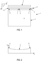
- FIG. 1 A first example of implementation of the manufacturing process is illustrated on figure 1 .
- a powder layer must be formed to cover the whole of the target surface 4.
- the injector 6 is moved, from a rest position, transversely with respect to the working surface 2, to distribute the powder along at least one transverse line L, over a transverse distance corresponding to the transverse dimension of the target surface 4.
- the line L of powder has a longitudinal dimension which can be adapted. This longitudinal dimension depends in particular on the dimension of the outlet of the injector 6.
- the forward movement of the injector 6, during which powder is dispensed is carried out from left to right, and the amount of powder dispensed by the injector 6 along the transverse direction is regulated so that it is greater near the ends La and Lb of the line L, to compensate for the tongue effect.
- the powder height of the distributed powder line L is variable as a function of the transverse position on the line L of powder.
- the profile of the height of powder distributed along the same transverse direction is then for example in the form of a parabola, as illustrated in FIG. figure 2 .
- the quantity of powder distributed respectively at points A and B , respectively close to the ends L a and L b of the line L of powder is greater than the quantity of powder distributed at point C located substantially in the middle of the line L of powder, the three points A, B and C being substantially aligned transversely.
- the injector 6 can then be returned to its rest position in a return movement, to the left of the working surface 2 according to the example of figure 1 , to distribute a new line of powder for the next layer in a new forward movement, or to distribute the new line of powder during the return movement, from the final position reached during the formation of the previous line, to the right of the work surface 2 according to the example of figure 1 .
- a second example of implementation is illustrated on figure 3 , in which the injector 6 is movable along the longitudinal X axis in addition to being movable transversely.
- the shape of the part P to be manufactured is such that the layer of powder to be formed does not necessarily have to completely cover the target surface 4. Consequently, the point injector 6 has been previously moved longitudinally without dispensing powder, and then has been moved transversely so as to distribute powder along a line L whose transverse dimension is adjusted to that of the edge of the part P to manufacture.
- the profile of the height of powder distributed along the transverse direction of the line L of powder may be of parabolic shape, as in the first example of implementation, in order to limit the tongue effect.
- the punctual injector 6 moving along the longitudinal X axis and along the transverse Y axis therefore makes it possible to distribute the powder by optimizing the dimensions of the successive layers of powder with respect to the dimensions of the part to be manufactured, to limit the use in excess of powder, and also as a function of the position of the part P to be manufactured on the target surface 4, without having to fill the target surface 4. More precisely, the quantity of powder distributed on the working surface 2 as a function of the transverse direction is produced as a function of the dimensions and of the position on the target surface 4 of each slice of the part P to be manufactured.
- the tranche considered of the part P to be manufactured has dimensions smaller than the dimensions of the target surface 4, that is to say of the part support plate, it may be advantageous not to cover the target surface 4, but to form the layer of powder in a localized manner on the target surface 4.
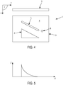
- FIG. 4 A third example of implementation of the method is illustrated on figures 4 and 5 , wherein the injector 6 is movable both transversely and longitudinally.
- the geometry of the wafer of part P to be manufactured has an edge that is inclined with respect to the transverse and longitudinal directions.
- the transverse dimension of the wafer is moreover less than the transverse dimension of the target surface 4.
- the trajectory of the injector 6 is then adapted accordingly, so as to distribute a line L of powder having a transverse component and a longitudinal component, approaching the inclined edge, and whose transverse dimension corresponds substantially to that of the slice of the part P to be manufactured.
- the amount of powder required for the wafer in question decreases transversely, in this case from left to right.
- the amount of powder dispensed by the injector 6 moving along the line L is then regulated accordingly, so that the profile of the height of powder dispensed along the transverse direction decreases from left to right.
- the quantity of powder dispensed is adjusted as a function of the geometry of the part P to be manufactured, and more precisely as a function of the geometry of the section considered of the part P to be manufactured.
- the volume of powder distributed on the working surface 2 is adjusted to the volume of powder required for the wafer in question.
- FIG. 6 A fourth example of implementation of the manufacturing process is illustrated on figures 6 and 7 .
- the point injector 6 is integral in movement along the longitudinal X axis of the spreading device 5, and is movable relative to the spreading device 5 along the transverse Y axis.
- the point injector 6 can be mounted on a slide along the transverse Y axis which is rigidly fixed to the spreading device 5.
- the shape of the part P to be manufactured according to this fourth example is similar to that of the second example of implementation, so that the layer to be formed does not completely cover the target surface 4.
- the spreading device 5 and the injector 6 are moved at the same time from an initial position shown in broken lines on the figure 6 in a position as close as possible to the layer to be formed, shown in solid lines on the figure 6 .
- the point injector 6 is then moved along the transverse Y axis, along the spreading device 5, so as to distribute, as in the second embodiment, a line L of powder, the transverse dimension of which is adapted as a function. of the transverse dimension of the edge of the part P to be manufactured.
- the amount of powder along the powder line L is also adjusted, for example as in the second example to compensate for the tongue effect during spreading.
- the transverse movement of the powder injector 6 and the injection of powder can take place at the same time as the spreading device 5 moves longitudinally by example to adapt to a particular geometry as in the third example.
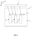
- the part P slice to be manufactured comprises three separate portions P 1 , P 2 and P 3.
- the regulation system regulates the quantity of powder distributed by the injector 6 to form a discontinuous line L on the working surface 2, that is to say that the line L of powder comprises three sections L respectively. 1 , L 2 , L 3 which are separate, and which correspond, in transverse dimension and in position, to the portions P 1 , P 2 and P 3 respectively of the wafer.
- the quantity of powder dispensed at any point can be determined, for example, by mass or by volume. As in the examples described here, the amount of powder distributed at any point on the trajectory of the injector 6 is determined by the height of the powder.
- the injector 6 can then also be movable relative to the working plane 2 along the vertical Z axis, for example to move along Z to follow the height of the powder dispensed.
- the injector 6 can also be used to distribute several materials.
- the injector 6 can prepare a first line of powder of a first material and a second line of powder of a second material, the two lines being spaced apart from one another longitudinally and / or transversely.
- the machine 1 comprises a single point injector 6, it may be otherwise.
- the machine 1 can comprise two point injectors 6, movable relative to the working surface 2, each ensuring the distribution of powder on the target surface 4 and allowing for example the use of identical or different powders.
- a second spreading device 5 can then advantageously be used with the second point injector 6.
- the use of an injector 6 dedicated to each type of material has the advantage of facilitating cleaning and monitoring of the batches of powder.
- the machine 1 can include as many injectors 6 as there are types of material that it is envisaged to use to manufacture the part P.
- the machine 1 can further comprise a mechanism for cleaning the working surface 2, so as to ensure that the injector 6 distributes a line of powder on the working surface 2 without any remaining residue. powder of the previous layer and therefore so as to ensure that the height of powder distributed on the working surface 2 by the injector 6 is known with precision.
- the cleaning mechanism is for example in the form of a squeegee movable relative to the working surface 2 making it possible to push the powder out of the working surface 2.
- the squeegee can be advantageously attached to the injector 6, so that once the injector 6 has dispensed a line of powder on the working surface 2 in a forward movement, the return movement of the injector 6, without dispensing powder, allows excess powder to be evacuated in its path.
- the squeegee can be unidirectional, that is to say it pushes the powder only for the same direction of movement. To increase the productivity of the machine, it may be advantageous not to return the injector to the same initial position to start each powder line.
- a retractable scraper is placed on each side of the injector 6 according to its direction of travel. The squeegee placed in front of the injector according to its direction of movement evacuates the powder remaining on the working surface 2 before the injector 6 distributes the powder while the squeegee placed on the other side is raised so as not to touch the powder that the injector has just dispensed.
- the squeegee also makes it possible to scrape the slag, that is to say the pieces of powder that are agglomerated but which are not part of the part P to be manufactured.
- the powder discharged by the squeegee can then be taken to a determined point on the working surface 2 where it is discharged through a dedicated orifice.
- the machine 1 can include a system for checking the amount of powder remaining on the working surface 2, before dispensing a new line L of powder for the next layer.
- the verification system may for example comprise a sensor for the height of powder remaining at any point of the working surface 2.
- the regulating device can thus adapt the distribution of powder by the injector 6 on the working surface 2 as a function of the quantity remaining to reach the determined quantity, and this at any point of the trajectory of the injector 6.
- the machine may include a system for checking the quantity of powder deposited on the receiving surface 11 making it possible to control in a closed loop the flow rate of powder delivered by the injector.
- the line L of powder, for each layer is located relative to the working surface 2 on a determined surface 7, called the receiving surface.
- the receiving surface 7 is movable relative to the working surface 2 in a vertical direction, so as to adjust the quantity of powder with increased precision.
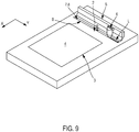
- the mobile receiving surface 7 is formed by an upper surface of a drawer 8 moving vertically in a groove 9 transverse to the working surface 2.
- the dimension of the drawer 8 is adapted to allow vertical sliding in the groove 9, with just sufficient play, and the outlet of the injector 6 is in contact with the working surface 2, so as to deposit powder only in the groove 9, on the receiving surface 7.
- the injector 6 moves transversely with respect to the working surface 2 to distribute the powder on the reception surface 7.
- the longitudinal dimension of the groove 9 being known, by adjusting the height of the injector 6 relative to the receiving surface 7 during the transverse movement of the injector 6, the volume of powder distributed in the groove is known with precision.
- the receiving surface 7 is moved vertically to a height that is controlled and known to be spread by the spreading device 5.
- the height of powder emerging out of the groove 9 is controlled and known.
- the powder distributed on the receiving surface 7 can be completely emerged, over its entire height, out of the groove 9, the receiving surface 7 being flush with the working surface 2. However, only part of the powder distributed on the receiving surface 7 can be emerged from the groove 7.
- the base of the injector 6 has a shape making it possible to cover the width of the groove 9 and the powder falls from the injector 6 substantially by gravity.
- the injector 6 is kept in the immediate vicinity of the working surface 2 during the injection of powder into the drawer 8 so that powder cannot slip between the working surface and the injector.
- the powder fills the volume of the drawer placed under the injector, it obstructs the entire opening of the injector 6 through which the powder flows, and there is no longer any flow of powder.
- the groove 9 optionally makes it possible to recover the excess powder.
- the spreader 5 having spread a layer of powder at least in part on the target surface 4 in a forward motion and the wafer of the part having been melted and solidified, the spreader 5 may be equipped to collect. the excess powder in a back motion.
- the drawer 8 having been lowered towards the bottom of the groove 9, the powder can fall on the receiving surface 7 or on the bottom of the groove 9.
- the machine 1 can then include a recovery system making it possible to evacuate the powder out. groove 9.
- the spreading device 5 can, in the same movement, spread a layer of powder on the target surface 4 and drop the excess powder. in a groove. Then, in the opposite movement, distribute a new layer of powder and drop the excess layer of this new layer into the other groove.
- the machine 1 may include one or two grooves making it possible to recover the excess powder, which are not associated with a drawer.
- the quantity of powder required can be adjusted as best as possible, taking into account various parameters such as the tongue effect, the geometry of the part, its dimensions, and its position on the target surface.
- the powder in excess with respect to the part P to be manufactured is therefore reduced.
- the cleaning operations of the machine 1 are limited. Indeed, in particular in the case where the dimensions of the part P to be manufactured are smaller than the dimensions of the part support plate, that is to say of the target surface 4, the powder can be distributed only on the target surface 4. even taking into account the compensation for the language effect during spreading. Thus, all the powder is located on the support plate, in the jacket 3, so that the cleaning of the powder, in particular when changing batches of powder, is reduced to the jacket.
- the injector 6 can be directly connected to a powder reservoir.
- the powder supply circuit then comprises for example the reservoir, the injector, and a flexible connecting the reservoir to the injector 6.
- a hopper for dosing the powder can be interposed in the circuit between the reservoir and the powder. 'injector 6.
- the injector 6 injecting the powder directly onto the working surface 2. Therefore, when the powder batch needs to be changed, in order to ensure that there is no powder left in the powder supply circuit, it can be taken out of the machine, cleaned completely, and then put back into the machine. the machine.
- the injector 6 is mounted in the machine 1 in a removable manner on a support, the support ensuring the guidance in transverse movement, and possibly longitudinal and in height, of the injector 6.
- a locking and unlocking system of the injector on its support is then provided so as to allow the withdrawal of the injector 6 from the machine 1 easily.
- the manufacturing time is also reduced, since the quantity of powder to be dispensed is reduced.
Landscapes
- Engineering & Computer Science (AREA)
- Chemical & Material Sciences (AREA)
- Materials Engineering (AREA)
- Manufacturing & Machinery (AREA)
- Physics & Mathematics (AREA)
- Optics & Photonics (AREA)
- Mechanical Engineering (AREA)
- Plasma & Fusion (AREA)
- Automation & Control Theory (AREA)
- Powder Metallurgy (AREA)
Claims (9)
- Verfahren zur additiven Fertigung eines Teils (P) durch partielles oder vollständiges selektives Schmelzen eines Pulvers in einer Maschine (1), umfassend:- eine Arbeitsfläche (2), die dazu bestimmt ist, eine Pulverschicht aufzunehmen,- eine Ausbreitvorrichtung (5) zum Ausbreiten der Pulverschicht in mindestens eine horizontale Längsrichtung auf der Arbeitsfläche (2),- mindestens einen Injektor (6), um Pulver direkt auf die Arbeitsfläche (2) zu injizieren, wobei der Injektor (6) in Bezug auf die Arbeitsfläche (2) in mindestens eine horizontale Querrichtung beweglich ist,- ein System zur Regulierung der vom Injektor (6) ausgegebenen Pulvermenge, wobei das Verfahren die folgenden Schritte umfasst:- Bewegen des Injektors (6) entlang einer Bahn, die mindestens eine zur horizontalen Querrichtung parallele Komponente umfasst, so dass Pulver auf der Arbeitsfläche (2) entlang einer Linie (L) ausgegeben wird;- Regulieren der vom Injektor (6) ausgegebenen Pulvermenge an jedem Punkt der Bahn des Injektors (6), wobei die Pulverhöhe der ausgegebenen Pulverlinie L in Abhängigkeit von der Querposition auf der Pulverlinie L variabel ist.
- Verfahren zur additiven Fertigung nach Anspruch 1, bei dem der Injektor (6) in Bezug auf die Arbeitsfläche (2) in Längsrichtung beweglich ist.
- Verfahren zur additiven Fertigung nach Anspruch 2, bei dem der Injektor (6) in Längsrichtung fest mit der Ausbreitvorrichtung (5) verbunden ist.
- Verfahren zur additiven Fertigung nach einem der vorhergehenden Ansprüche, bei dem der Injektor (6) lösbar in der Maschine (1) montiert ist.
- Verfahren zur additiven Fertigung nach einem der vorhergehenden Ansprüche, bei dem der Injektor (6) in Bezug auf die Arbeitsfläche (2) in eine vertikale Richtung beweglich ist, wobei das Regulierungssystem die vertikale Position des Injektors (6) in Bezug auf die Arbeitsfläche (2) regelt.
- Verfahren zur additiven Fertigung nach einem der vorhergehenden Ansprüche, wobei der Schritt, der darin besteht, die vom Injektor (6) ausgegebene Pulvermenge an jedem Punkt der Bahn des Injektors (6) zu regulieren, in Abhängigkeit von der Geometrie des zu fertigenden Teils (P) ausgeführt wird.
- Verfahren zur additiven Fertigung nach einem der vorhergehenden Ansprüche, wobei der Schritt, der darin besteht, die vom Injektor (6) ausgegebene Pulvermenge an jedem Punkt der Bahn des Injektors (6) zu regulieren, in Abhängigkeit von den Abmessungen des zu fertigenden Teils (P) ausgeführt wird.
- Verfahren zur additiven Fertigung nach einem der vorhergehenden Ansprüche, wobei der Schritt, der darin besteht, die vom Injektor (6) ausgegebene Pulvermenge an jedem Punkt der Bahn des Injektors (6) zu regulieren, in Abhängigkeit von der Position des zu fertigenden Teils (P) ausgeführt auf der Arbeitsfläche (2) ausgeführt wird.
- Verfahren zur additiven Fertigung nach einem der vorhergehenden Ansprüche, wobei der Schritt, der darin besteht, die vom Injektor (6) ausgegebene Pulvermenge an jedem Punkt der Bahn des Injektors (6) zu regulieren, in Abhängigkeit vom Werkstoff des Bereichs des zu fertigenden Teils (P) auf der Arbeitsfläche (2) ausgeführt wird.
Applications Claiming Priority (2)
| Application Number | Priority Date | Filing Date | Title |
|---|---|---|---|
| FR1563249A FR3046094A1 (fr) | 2015-12-23 | 2015-12-23 | Procede de fabrication additive d'une piece par fusion selective totale ou partielle d'une poudre et machine adaptee a la mise en oeuvre d'un tel procede |
| PCT/EP2016/082038 WO2017108867A1 (fr) | 2015-12-23 | 2016-12-20 | Procede de fabrication additive comprenant une etape de distribution de poudre par un injecteur |
Publications (2)
| Publication Number | Publication Date |
|---|---|
| EP3393697A1 EP3393697A1 (de) | 2018-10-31 |
| EP3393697B1 true EP3393697B1 (de) | 2021-11-03 |
Family
ID=55759745
Family Applications (1)
| Application Number | Title | Priority Date | Filing Date |
|---|---|---|---|
| EP16819076.7A Active EP3393697B1 (de) | 2015-12-23 | 2016-12-20 | Verfahren zur generativen fertigung mit einem pulververteilungsschritt durch einen injektor |
Country Status (7)
| Country | Link |
|---|---|
| US (1) | US11292059B2 (de) |
| EP (1) | EP3393697B1 (de) |
| JP (1) | JP6896739B2 (de) |
| KR (1) | KR102647672B1 (de) |
| CN (1) | CN108367352B (de) |
| FR (1) | FR3046094A1 (de) |
| WO (1) | WO2017108867A1 (de) |
Families Citing this family (7)
| Publication number | Priority date | Publication date | Assignee | Title |
|---|---|---|---|---|
| DE102017218175A1 (de) | 2017-10-11 | 2019-04-11 | Eos Gmbh Electro Optical Systems | Dosiervorrichtung, Vorrichtung und Verfahren zum generativen Herstellen eines dreidimensionalen Objekts |
| FR3087139B1 (fr) | 2018-10-16 | 2020-10-02 | Addup | Machine de fabrication additive comprenant une distribution de poudre mobile et regulee |
| DE102018128242B4 (de) | 2018-11-12 | 2025-02-20 | Nikon Slm Solutions Ag | Pulverauftragsvorrichtung, Verfahren zum Betreiben einer Pulverauftragsvorrichtung und Anlage zur Herstellung eines dreidimensionalen Werkstücks |
| FR3094665B1 (fr) * | 2019-04-08 | 2024-03-15 | Addup | Machine de fabrication additive comprenant une surface de réception de poudre mobile et optimisée pour retenir les grains de poudre |
| FR3096284B1 (fr) | 2019-05-24 | 2023-03-24 | Addup | Machine de fabrication additive à distribution de poudre par tamisage. |
| US11638959B2 (en) | 2020-09-03 | 2023-05-02 | General Electric Company | Systems and methods for estimating powder dosing in additive manufacturing processes |
| CN112030156A (zh) * | 2020-09-04 | 2020-12-04 | 浙江工业大学之江学院 | 用于激光熔覆的可调式预置铺粉装置 |
Family Cites Families (22)
| Publication number | Priority date | Publication date | Assignee | Title |
|---|---|---|---|---|
| KR960008015B1 (ko) | 1986-10-17 | 1996-06-19 | 보드 오브 리젼츠, 디 유니버시티 오브 텍사스 시스템 | 선택적 소결에 의한 부품의 제조 방법 및 장치 |
| US5252264A (en) | 1991-11-08 | 1993-10-12 | Dtm Corporation | Apparatus and method for producing parts with multi-directional powder delivery |
| CN2372077Y (zh) * | 1999-05-05 | 2000-04-05 | 华中理工大学 | 双轴联动扫描式选择性激光烧结装置 |
| CN1252297C (zh) * | 2003-11-28 | 2006-04-19 | 清华大学 | 激光合成制备金属间化合物及其颗粒增强复合材料的方法 |
| WO2005097476A2 (en) * | 2004-04-02 | 2005-10-20 | Z Corporation | Methods and apparatus for 3d printing |
| US20050263934A1 (en) * | 2004-05-28 | 2005-12-01 | 3D Systems, Inc. | Single side feed parked powder wave heating with wave flattener |
| CN1295051C (zh) * | 2004-12-15 | 2007-01-17 | 华中科技大学 | 一种直接制造金属零件的快速成形系统 |
| JP4351218B2 (ja) | 2006-02-20 | 2009-10-28 | 株式会社松浦機械製作所 | 三次元造形製品の製造装置 |
| DE112007002411T5 (de) | 2006-10-10 | 2009-07-30 | Shofu Inc. | Datenerzeugungssystem, Herstellungsverfahren und modelldatenerzeugendes Programm |
| ITPI20070108A1 (it) * | 2007-09-17 | 2009-03-18 | Enrico Dini | Metodo perfezionato per la realizzazione automatica di strutture di conglomerato |
| CN102015258B (zh) | 2008-04-21 | 2013-03-27 | 松下电器产业株式会社 | 层叠造形装置 |
| GB0813242D0 (en) | 2008-07-18 | 2008-08-27 | Mcp Tooling Technologies Ltd | Powder dispensing apparatus and method |
| JP5861117B2 (ja) * | 2011-05-30 | 2016-02-16 | パナソニックIpマネジメント株式会社 | 三次元形状造形物の製造方法および製造装置 |
| FR2984191B1 (fr) | 2011-12-20 | 2014-01-10 | Michelin Soc Tech | Machine et procede pour la fabrication additive a base de poudre |
| FR2991208B1 (fr) * | 2012-06-01 | 2014-06-06 | Michelin & Cie | Machine et procede pour la fabrication additive a base de poudre |
| CN103071795B (zh) * | 2013-01-23 | 2016-03-02 | 西安铂力特激光成形技术有限公司 | 移动振镜选择性激光熔化slm成形设备 |
| US9308583B2 (en) | 2013-03-05 | 2016-04-12 | Lawrence Livermore National Security, Llc | System and method for high power diode based additive manufacturing |
| CN103737932B (zh) * | 2014-01-07 | 2016-02-24 | 清华大学 | 用于三维打印系统的粉末混合装置和三维打印系统 |
| EP3132919B1 (de) * | 2014-04-14 | 2019-03-27 | Konica Minolta, Inc. | Vorrichtung zur herstellung eines dreidimensionalen gefertigten objekts und herstellungsverfahren |
| CN106488819B (zh) * | 2014-06-20 | 2018-06-22 | 维洛3D公司 | 用于三维打印的设备、系统和方法 |
| DE102015223719A1 (de) * | 2015-11-30 | 2017-06-01 | Eos Gmbh Electro Optical Systems | Verfahren und Vorrichtung zur Aufbaumaterialbedarfsermittlung |
| FR3046095B1 (fr) | 2015-12-23 | 2018-01-26 | Addup | Machine de fabrication additive et procede de fabrication additive mettant en oeuvre une telle machine |
-
2015
- 2015-12-23 FR FR1563249A patent/FR3046094A1/fr not_active Ceased
-
2016
- 2016-12-20 US US16/065,692 patent/US11292059B2/en active Active
- 2016-12-20 KR KR1020187017511A patent/KR102647672B1/ko active Active
- 2016-12-20 WO PCT/EP2016/082038 patent/WO2017108867A1/fr not_active Ceased
- 2016-12-20 CN CN201680074926.2A patent/CN108367352B/zh active Active
- 2016-12-20 EP EP16819076.7A patent/EP3393697B1/de active Active
- 2016-12-20 JP JP2018532324A patent/JP6896739B2/ja active Active
Non-Patent Citations (1)
| Title |
|---|
| None * |
Also Published As
| Publication number | Publication date |
|---|---|
| FR3046094A1 (fr) | 2017-06-30 |
| KR102647672B1 (ko) | 2024-03-15 |
| WO2017108867A1 (fr) | 2017-06-29 |
| EP3393697A1 (de) | 2018-10-31 |
| JP6896739B2 (ja) | 2021-06-30 |
| US20200269510A1 (en) | 2020-08-27 |
| KR20180097568A (ko) | 2018-08-31 |
| JP2019501293A (ja) | 2019-01-17 |
| CN108367352A (zh) | 2018-08-03 |
| CN108367352B (zh) | 2021-07-13 |
| US11292059B2 (en) | 2022-04-05 |
Similar Documents
| Publication | Publication Date | Title |
|---|---|---|
| EP3393697B1 (de) | Verfahren zur generativen fertigung mit einem pulververteilungsschritt durch einen injektor | |
| EP3393698B1 (de) | Maschine zur generativen fertigung mit einem pulververteilungssystem mit einer schale und einem injektor | |
| EP2670547B1 (de) | Sinter- und laserfusionsvorrichtung mit einer vorrichtung zum erwärmen von pulver durch induktion | |
| EP1235650B1 (de) | Vorrichtung und verfahren zum aufbringen einer dünnen schicht eines pulverförmigen materials | |
| EP2477769B1 (de) | Verfahren zur hestellung von objekten mittels laser aus mindestens zwei unterschieldichen pulverwerkstoffen und entsprechende herstellungsanlage | |
| EP2855055B1 (de) | Maschine und verfahren zur herstellung eines auf pulver basierenden additivs | |
| EP3369555A1 (de) | Verfahren und maschine zur herstellung von bauteilen mithilfe der technik der additiven fertigung mit pastösen stoffen und perfektionierter stoffzufuhr | |
| EP2794153A1 (de) | Maschine und verfahren zum herstellen eines auf pulver basierenden zusatzstoffs | |
| WO2020089538A1 (fr) | Machine de fabrication additive comprenant une distribution de poudre mobile et regulee | |
| FR3035606B1 (fr) | Dispositif de transfert de poudre et procede pour fabrication additive | |
| EP2737964A1 (de) | Pulverschmelzverfahren mit Beheizung der an das Schmelzbad angrenzenden Zone | |
| WO2013064767A1 (fr) | Installation de fabrication de pièces par fusion sélective de poudre | |
| EP3996920A1 (de) | Vorrichtung und verfahren zur abscheidung eines körnigen materials in der generativen fertigung | |
| FR3081755A1 (fr) | Racleur, applicable au transport de poudres | |
| FR3116461A1 (fr) | Machine de fabrication de pièces crues en matériau céramique ou métallique | |
| FR3090459A1 (fr) | Machine améliorée de fabrication additive d’une pièce et procédé associé | |
| FR3098751A1 (fr) | Procédé de fabrication additive utilisant un pochoir | |
| EP3953149B1 (de) | Maschine zur generativen fertigung mit einer beweglichen oberfläche zur aufnahme von pulver, die so optimiert ist, dass sie die pulverkörner zurückhält | |
| WO2002045940A1 (fr) | Procede et dispositif de fabrication de pieces tridimensionnelles en materiaux thermoplastiques fusibles | |
| FR3102079A1 (fr) | Procédé de fabrication additive sur lits de poudre d’une pièce permettant une diminution, voire une suppression, des éléments de maintien habituellement nécessaires | |
| FR3088837A1 (fr) | Racleur pour une fabrication additive de pieces metalliques par procede de lit de poudre |
Legal Events
| Date | Code | Title | Description |
|---|---|---|---|
| STAA | Information on the status of an ep patent application or granted ep patent |
Free format text: STATUS: UNKNOWN |
|
| STAA | Information on the status of an ep patent application or granted ep patent |
Free format text: STATUS: THE INTERNATIONAL PUBLICATION HAS BEEN MADE |
|
| PUAI | Public reference made under article 153(3) epc to a published international application that has entered the european phase |
Free format text: ORIGINAL CODE: 0009012 |
|
| STAA | Information on the status of an ep patent application or granted ep patent |
Free format text: STATUS: REQUEST FOR EXAMINATION WAS MADE |
|
| 17P | Request for examination filed |
Effective date: 20180723 |
|
| AK | Designated contracting states |
Kind code of ref document: A1 Designated state(s): AL AT BE BG CH CY CZ DE DK EE ES FI FR GB GR HR HU IE IS IT LI LT LU LV MC MK MT NL NO PL PT RO RS SE SI SK SM TR |
|
| AX | Request for extension of the european patent |
Extension state: BA ME |
|
| DAV | Request for validation of the european patent (deleted) | ||
| DAX | Request for extension of the european patent (deleted) | ||
| STAA | Information on the status of an ep patent application or granted ep patent |
Free format text: STATUS: EXAMINATION IS IN PROGRESS |
|
| 17Q | First examination report despatched |
Effective date: 20190612 |
|
| REG | Reference to a national code |
Ref country code: DE Ref legal event code: R079 Ref document number: 602016065800 Country of ref document: DE Free format text: PREVIOUS MAIN CLASS: B22F0003105000 Ipc: B33Y0010000000 |
|
| RIC1 | Information provided on ipc code assigned before grant |
Ipc: B22F 12/57 20210101ALI20210519BHEP Ipc: B22F 10/37 20210101ALI20210519BHEP Ipc: B22F 12/53 20210101ALI20210519BHEP Ipc: B22F 10/28 20210101ALI20210519BHEP Ipc: B29C 64/209 20170101ALI20210519BHEP Ipc: B29C 64/205 20170101ALI20210519BHEP Ipc: B29C 64/35 20170101ALI20210519BHEP Ipc: B29C 64/153 20170101ALI20210519BHEP Ipc: B29C 64/141 20170101ALI20210519BHEP Ipc: B33Y 10/00 20150101AFI20210519BHEP |
|
| GRAP | Despatch of communication of intention to grant a patent |
Free format text: ORIGINAL CODE: EPIDOSNIGR1 |
|
| STAA | Information on the status of an ep patent application or granted ep patent |
Free format text: STATUS: GRANT OF PATENT IS INTENDED |
|
| INTG | Intention to grant announced |
Effective date: 20210625 |
|
| RAP3 | Party data changed (applicant data changed or rights of an application transferred) |
Owner name: ADDUP |
|
| GRAS | Grant fee paid |
Free format text: ORIGINAL CODE: EPIDOSNIGR3 |
|
| GRAA | (expected) grant |
Free format text: ORIGINAL CODE: 0009210 |
|
| STAA | Information on the status of an ep patent application or granted ep patent |
Free format text: STATUS: THE PATENT HAS BEEN GRANTED |
|
| AK | Designated contracting states |
Kind code of ref document: B1 Designated state(s): AL AT BE BG CH CY CZ DE DK EE ES FI FR GB GR HR HU IE IS IT LI LT LU LV MC MK MT NL NO PL PT RO RS SE SI SK SM TR |
|
| REG | Reference to a national code |
Ref country code: GB Ref legal event code: FG4D Free format text: NOT ENGLISH |
|
| REG | Reference to a national code |
Ref country code: AT Ref legal event code: REF Ref document number: 1443624 Country of ref document: AT Kind code of ref document: T Effective date: 20211115 Ref country code: CH Ref legal event code: EP |
|
| REG | Reference to a national code |
Ref country code: DE Ref legal event code: R096 Ref document number: 602016065800 Country of ref document: DE |
|
| REG | Reference to a national code |
Ref country code: IE Ref legal event code: FG4D Free format text: LANGUAGE OF EP DOCUMENT: FRENCH |
|
| REG | Reference to a national code |
Ref country code: SE Ref legal event code: TRGR |
|
| REG | Reference to a national code |
Ref country code: LT Ref legal event code: MG9D |
|
| REG | Reference to a national code |
Ref country code: NL Ref legal event code: MP Effective date: 20211103 |
|
| REG | Reference to a national code |
Ref country code: AT Ref legal event code: MK05 Ref document number: 1443624 Country of ref document: AT Kind code of ref document: T Effective date: 20211103 |
|
| PG25 | Lapsed in a contracting state [announced via postgrant information from national office to epo] |
Ref country code: RS Free format text: LAPSE BECAUSE OF FAILURE TO SUBMIT A TRANSLATION OF THE DESCRIPTION OR TO PAY THE FEE WITHIN THE PRESCRIBED TIME-LIMIT Effective date: 20211103 Ref country code: LT Free format text: LAPSE BECAUSE OF FAILURE TO SUBMIT A TRANSLATION OF THE DESCRIPTION OR TO PAY THE FEE WITHIN THE PRESCRIBED TIME-LIMIT Effective date: 20211103 Ref country code: FI Free format text: LAPSE BECAUSE OF FAILURE TO SUBMIT A TRANSLATION OF THE DESCRIPTION OR TO PAY THE FEE WITHIN THE PRESCRIBED TIME-LIMIT Effective date: 20211103 Ref country code: BG Free format text: LAPSE BECAUSE OF FAILURE TO SUBMIT A TRANSLATION OF THE DESCRIPTION OR TO PAY THE FEE WITHIN THE PRESCRIBED TIME-LIMIT Effective date: 20220203 Ref country code: AT Free format text: LAPSE BECAUSE OF FAILURE TO SUBMIT A TRANSLATION OF THE DESCRIPTION OR TO PAY THE FEE WITHIN THE PRESCRIBED TIME-LIMIT Effective date: 20211103 |
|
| PG25 | Lapsed in a contracting state [announced via postgrant information from national office to epo] |
Ref country code: IS Free format text: LAPSE BECAUSE OF FAILURE TO SUBMIT A TRANSLATION OF THE DESCRIPTION OR TO PAY THE FEE WITHIN THE PRESCRIBED TIME-LIMIT Effective date: 20220303 Ref country code: PT Free format text: LAPSE BECAUSE OF FAILURE TO SUBMIT A TRANSLATION OF THE DESCRIPTION OR TO PAY THE FEE WITHIN THE PRESCRIBED TIME-LIMIT Effective date: 20220303 Ref country code: PL Free format text: LAPSE BECAUSE OF FAILURE TO SUBMIT A TRANSLATION OF THE DESCRIPTION OR TO PAY THE FEE WITHIN THE PRESCRIBED TIME-LIMIT Effective date: 20211103 Ref country code: NO Free format text: LAPSE BECAUSE OF FAILURE TO SUBMIT A TRANSLATION OF THE DESCRIPTION OR TO PAY THE FEE WITHIN THE PRESCRIBED TIME-LIMIT Effective date: 20220203 Ref country code: NL Free format text: LAPSE BECAUSE OF FAILURE TO SUBMIT A TRANSLATION OF THE DESCRIPTION OR TO PAY THE FEE WITHIN THE PRESCRIBED TIME-LIMIT Effective date: 20211103 Ref country code: LV Free format text: LAPSE BECAUSE OF FAILURE TO SUBMIT A TRANSLATION OF THE DESCRIPTION OR TO PAY THE FEE WITHIN THE PRESCRIBED TIME-LIMIT Effective date: 20211103 Ref country code: HR Free format text: LAPSE BECAUSE OF FAILURE TO SUBMIT A TRANSLATION OF THE DESCRIPTION OR TO PAY THE FEE WITHIN THE PRESCRIBED TIME-LIMIT Effective date: 20211103 Ref country code: GR Free format text: LAPSE BECAUSE OF FAILURE TO SUBMIT A TRANSLATION OF THE DESCRIPTION OR TO PAY THE FEE WITHIN THE PRESCRIBED TIME-LIMIT Effective date: 20220204 Ref country code: ES Free format text: LAPSE BECAUSE OF FAILURE TO SUBMIT A TRANSLATION OF THE DESCRIPTION OR TO PAY THE FEE WITHIN THE PRESCRIBED TIME-LIMIT Effective date: 20211103 |
|
| PG25 | Lapsed in a contracting state [announced via postgrant information from national office to epo] |
Ref country code: SM Free format text: LAPSE BECAUSE OF FAILURE TO SUBMIT A TRANSLATION OF THE DESCRIPTION OR TO PAY THE FEE WITHIN THE PRESCRIBED TIME-LIMIT Effective date: 20211103 Ref country code: SK Free format text: LAPSE BECAUSE OF FAILURE TO SUBMIT A TRANSLATION OF THE DESCRIPTION OR TO PAY THE FEE WITHIN THE PRESCRIBED TIME-LIMIT Effective date: 20211103 Ref country code: RO Free format text: LAPSE BECAUSE OF FAILURE TO SUBMIT A TRANSLATION OF THE DESCRIPTION OR TO PAY THE FEE WITHIN THE PRESCRIBED TIME-LIMIT Effective date: 20211103 Ref country code: EE Free format text: LAPSE BECAUSE OF FAILURE TO SUBMIT A TRANSLATION OF THE DESCRIPTION OR TO PAY THE FEE WITHIN THE PRESCRIBED TIME-LIMIT Effective date: 20211103 Ref country code: DK Free format text: LAPSE BECAUSE OF FAILURE TO SUBMIT A TRANSLATION OF THE DESCRIPTION OR TO PAY THE FEE WITHIN THE PRESCRIBED TIME-LIMIT Effective date: 20211103 Ref country code: CZ Free format text: LAPSE BECAUSE OF FAILURE TO SUBMIT A TRANSLATION OF THE DESCRIPTION OR TO PAY THE FEE WITHIN THE PRESCRIBED TIME-LIMIT Effective date: 20211103 |
|
| REG | Reference to a national code |
Ref country code: CH Ref legal event code: PL |
|
| REG | Reference to a national code |
Ref country code: DE Ref legal event code: R097 Ref document number: 602016065800 Country of ref document: DE |
|
| PG25 | Lapsed in a contracting state [announced via postgrant information from national office to epo] |
Ref country code: MC Free format text: LAPSE BECAUSE OF FAILURE TO SUBMIT A TRANSLATION OF THE DESCRIPTION OR TO PAY THE FEE WITHIN THE PRESCRIBED TIME-LIMIT Effective date: 20211103 |
|
| PLBE | No opposition filed within time limit |
Free format text: ORIGINAL CODE: 0009261 |
|
| STAA | Information on the status of an ep patent application or granted ep patent |
Free format text: STATUS: NO OPPOSITION FILED WITHIN TIME LIMIT |
|
| REG | Reference to a national code |
Ref country code: BE Ref legal event code: MM Effective date: 20211231 |
|
| 26N | No opposition filed |
Effective date: 20220804 |
|
| GBPC | Gb: european patent ceased through non-payment of renewal fee |
Effective date: 20220203 |
|
| PG25 | Lapsed in a contracting state [announced via postgrant information from national office to epo] |
Ref country code: LU Free format text: LAPSE BECAUSE OF NON-PAYMENT OF DUE FEES Effective date: 20211220 Ref country code: IE Free format text: LAPSE BECAUSE OF NON-PAYMENT OF DUE FEES Effective date: 20211220 Ref country code: AL Free format text: LAPSE BECAUSE OF FAILURE TO SUBMIT A TRANSLATION OF THE DESCRIPTION OR TO PAY THE FEE WITHIN THE PRESCRIBED TIME-LIMIT Effective date: 20211103 |
|
| PG25 | Lapsed in a contracting state [announced via postgrant information from national office to epo] |
Ref country code: SI Free format text: LAPSE BECAUSE OF FAILURE TO SUBMIT A TRANSLATION OF THE DESCRIPTION OR TO PAY THE FEE WITHIN THE PRESCRIBED TIME-LIMIT Effective date: 20211103 Ref country code: BE Free format text: LAPSE BECAUSE OF NON-PAYMENT OF DUE FEES Effective date: 20211231 |
|
| PG25 | Lapsed in a contracting state [announced via postgrant information from national office to epo] |
Ref country code: LI Free format text: LAPSE BECAUSE OF NON-PAYMENT OF DUE FEES Effective date: 20211231 Ref country code: CH Free format text: LAPSE BECAUSE OF NON-PAYMENT OF DUE FEES Effective date: 20211231 |
|
| PG25 | Lapsed in a contracting state [announced via postgrant information from national office to epo] |
Ref country code: GB Free format text: LAPSE BECAUSE OF NON-PAYMENT OF DUE FEES Effective date: 20220203 |
|
| PG25 | Lapsed in a contracting state [announced via postgrant information from national office to epo] |
Ref country code: CY Free format text: LAPSE BECAUSE OF FAILURE TO SUBMIT A TRANSLATION OF THE DESCRIPTION OR TO PAY THE FEE WITHIN THE PRESCRIBED TIME-LIMIT Effective date: 20211103 |
|
| PG25 | Lapsed in a contracting state [announced via postgrant information from national office to epo] |
Ref country code: HU Free format text: LAPSE BECAUSE OF FAILURE TO SUBMIT A TRANSLATION OF THE DESCRIPTION OR TO PAY THE FEE WITHIN THE PRESCRIBED TIME-LIMIT; INVALID AB INITIO Effective date: 20161220 |
|
| PG25 | Lapsed in a contracting state [announced via postgrant information from national office to epo] |
Ref country code: MK Free format text: LAPSE BECAUSE OF FAILURE TO SUBMIT A TRANSLATION OF THE DESCRIPTION OR TO PAY THE FEE WITHIN THE PRESCRIBED TIME-LIMIT Effective date: 20211103 |
|
| PG25 | Lapsed in a contracting state [announced via postgrant information from national office to epo] |
Ref country code: MT Free format text: LAPSE BECAUSE OF FAILURE TO SUBMIT A TRANSLATION OF THE DESCRIPTION OR TO PAY THE FEE WITHIN THE PRESCRIBED TIME-LIMIT Effective date: 20211103 |
|
| PGFP | Annual fee paid to national office [announced via postgrant information from national office to epo] |
Ref country code: DE Payment date: 20241121 Year of fee payment: 9 |
|
| PGFP | Annual fee paid to national office [announced via postgrant information from national office to epo] |
Ref country code: IT Payment date: 20241121 Year of fee payment: 9 |
|
| PGFP | Annual fee paid to national office [announced via postgrant information from national office to epo] |
Ref country code: SE Payment date: 20241121 Year of fee payment: 9 |
|
| PG25 | Lapsed in a contracting state [announced via postgrant information from national office to epo] |
Ref country code: TR Free format text: LAPSE BECAUSE OF FAILURE TO SUBMIT A TRANSLATION OF THE DESCRIPTION OR TO PAY THE FEE WITHIN THE PRESCRIBED TIME-LIMIT Effective date: 20211103 |
|
| PGFP | Annual fee paid to national office [announced via postgrant information from national office to epo] |
Ref country code: FR Payment date: 20251120 Year of fee payment: 10 |