EP3393572B1 - Needleless syringe connector cap and container - Google Patents
Needleless syringe connector cap and container Download PDFInfo
- Publication number
- EP3393572B1 EP3393572B1 EP16825584.2A EP16825584A EP3393572B1 EP 3393572 B1 EP3393572 B1 EP 3393572B1 EP 16825584 A EP16825584 A EP 16825584A EP 3393572 B1 EP3393572 B1 EP 3393572B1
- Authority
- EP
- European Patent Office
- Prior art keywords
- passage
- tip
- container
- syringe
- cross
- Prior art date
- Legal status (The legal status is an assumption and is not a legal conclusion. Google has not performed a legal analysis and makes no representation as to the accuracy of the status listed.)
- Active
Links
- 239000012530 fluid Substances 0.000 claims description 89
- 238000007789 sealing Methods 0.000 claims description 47
- 238000005273 aeration Methods 0.000 claims description 11
- 239000004033 plastic Substances 0.000 claims description 11
- 229920003023 plastic Polymers 0.000 claims description 11
- 238000003780 insertion Methods 0.000 claims description 9
- 230000037431 insertion Effects 0.000 claims description 9
- 238000000034 method Methods 0.000 claims description 6
- 230000000717 retained effect Effects 0.000 claims description 2
- 239000011888 foil Substances 0.000 description 11
- 239000000463 material Substances 0.000 description 4
- 239000003814 drug Substances 0.000 description 3
- 229940079593 drug Drugs 0.000 description 3
- 239000012528 membrane Substances 0.000 description 3
- 239000012080 ambient air Substances 0.000 description 2
- 230000009286 beneficial effect Effects 0.000 description 2
- 229920001971 elastomer Polymers 0.000 description 2
- 239000000758 substrate Substances 0.000 description 2
- 230000015572 biosynthetic process Effects 0.000 description 1
- 239000000806 elastomer Substances 0.000 description 1
- 229920002457 flexible plastic Polymers 0.000 description 1
- 239000011521 glass Substances 0.000 description 1
- 238000002347 injection Methods 0.000 description 1
- 239000007924 injection Substances 0.000 description 1
- 239000002991 molded plastic Substances 0.000 description 1
- 230000035515 penetration Effects 0.000 description 1
- 239000007787 solid Substances 0.000 description 1
Images


Classifications
-
- A—HUMAN NECESSITIES
- A61—MEDICAL OR VETERINARY SCIENCE; HYGIENE
- A61J—CONTAINERS SPECIALLY ADAPTED FOR MEDICAL OR PHARMACEUTICAL PURPOSES; DEVICES OR METHODS SPECIALLY ADAPTED FOR BRINGING PHARMACEUTICAL PRODUCTS INTO PARTICULAR PHYSICAL OR ADMINISTERING FORMS; DEVICES FOR ADMINISTERING FOOD OR MEDICINES ORALLY; BABY COMFORTERS; DEVICES FOR RECEIVING SPITTLE
- A61J1/00—Containers specially adapted for medical or pharmaceutical purposes
- A61J1/14—Details; Accessories therefor
- A61J1/1406—Septums, pierceable membranes
-
- A—HUMAN NECESSITIES
- A61—MEDICAL OR VETERINARY SCIENCE; HYGIENE
- A61J—CONTAINERS SPECIALLY ADAPTED FOR MEDICAL OR PHARMACEUTICAL PURPOSES; DEVICES OR METHODS SPECIALLY ADAPTED FOR BRINGING PHARMACEUTICAL PRODUCTS INTO PARTICULAR PHYSICAL OR ADMINISTERING FORMS; DEVICES FOR ADMINISTERING FOOD OR MEDICINES ORALLY; BABY COMFORTERS; DEVICES FOR RECEIVING SPITTLE
- A61J1/00—Containers specially adapted for medical or pharmaceutical purposes
- A61J1/14—Details; Accessories therefor
- A61J1/20—Arrangements for transferring or mixing fluids, e.g. from vial to syringe
- A61J1/2003—Accessories used in combination with means for transfer or mixing of fluids, e.g. for activating fluid flow, separating fluids, filtering fluid or venting
- A61J1/202—Separating means
- A61J1/2037—Separating means having valve means
-
- A—HUMAN NECESSITIES
- A61—MEDICAL OR VETERINARY SCIENCE; HYGIENE
- A61J—CONTAINERS SPECIALLY ADAPTED FOR MEDICAL OR PHARMACEUTICAL PURPOSES; DEVICES OR METHODS SPECIALLY ADAPTED FOR BRINGING PHARMACEUTICAL PRODUCTS INTO PARTICULAR PHYSICAL OR ADMINISTERING FORMS; DEVICES FOR ADMINISTERING FOOD OR MEDICINES ORALLY; BABY COMFORTERS; DEVICES FOR RECEIVING SPITTLE
- A61J1/00—Containers specially adapted for medical or pharmaceutical purposes
- A61J1/14—Details; Accessories therefor
- A61J1/1412—Containers with closing means, e.g. caps
- A61J1/1418—Threaded type
-
- A—HUMAN NECESSITIES
- A61—MEDICAL OR VETERINARY SCIENCE; HYGIENE
- A61J—CONTAINERS SPECIALLY ADAPTED FOR MEDICAL OR PHARMACEUTICAL PURPOSES; DEVICES OR METHODS SPECIALLY ADAPTED FOR BRINGING PHARMACEUTICAL PRODUCTS INTO PARTICULAR PHYSICAL OR ADMINISTERING FORMS; DEVICES FOR ADMINISTERING FOOD OR MEDICINES ORALLY; BABY COMFORTERS; DEVICES FOR RECEIVING SPITTLE
- A61J1/00—Containers specially adapted for medical or pharmaceutical purposes
- A61J1/14—Details; Accessories therefor
- A61J1/1475—Inlet or outlet ports
- A61J1/1487—Inlet or outlet ports with friction fit, e.g. connecting tubes directly to a protruding port
-
- A—HUMAN NECESSITIES
- A61—MEDICAL OR VETERINARY SCIENCE; HYGIENE
- A61J—CONTAINERS SPECIALLY ADAPTED FOR MEDICAL OR PHARMACEUTICAL PURPOSES; DEVICES OR METHODS SPECIALLY ADAPTED FOR BRINGING PHARMACEUTICAL PRODUCTS INTO PARTICULAR PHYSICAL OR ADMINISTERING FORMS; DEVICES FOR ADMINISTERING FOOD OR MEDICINES ORALLY; BABY COMFORTERS; DEVICES FOR RECEIVING SPITTLE
- A61J1/00—Containers specially adapted for medical or pharmaceutical purposes
- A61J1/14—Details; Accessories therefor
- A61J1/20—Arrangements for transferring or mixing fluids, e.g. from vial to syringe
- A61J1/2003—Accessories used in combination with means for transfer or mixing of fluids, e.g. for activating fluid flow, separating fluids, filtering fluid or venting
- A61J1/2048—Connecting means
-
- A—HUMAN NECESSITIES
- A61—MEDICAL OR VETERINARY SCIENCE; HYGIENE
- A61J—CONTAINERS SPECIALLY ADAPTED FOR MEDICAL OR PHARMACEUTICAL PURPOSES; DEVICES OR METHODS SPECIALLY ADAPTED FOR BRINGING PHARMACEUTICAL PRODUCTS INTO PARTICULAR PHYSICAL OR ADMINISTERING FORMS; DEVICES FOR ADMINISTERING FOOD OR MEDICINES ORALLY; BABY COMFORTERS; DEVICES FOR RECEIVING SPITTLE
- A61J1/00—Containers specially adapted for medical or pharmaceutical purposes
- A61J1/14—Details; Accessories therefor
- A61J1/20—Arrangements for transferring or mixing fluids, e.g. from vial to syringe
- A61J1/2003—Accessories used in combination with means for transfer or mixing of fluids, e.g. for activating fluid flow, separating fluids, filtering fluid or venting
- A61J1/2068—Venting means
- A61J1/2072—Venting means for internal venting
-
- A—HUMAN NECESSITIES
- A61—MEDICAL OR VETERINARY SCIENCE; HYGIENE
- A61M—DEVICES FOR INTRODUCING MEDIA INTO, OR ONTO, THE BODY; DEVICES FOR TRANSDUCING BODY MEDIA OR FOR TAKING MEDIA FROM THE BODY; DEVICES FOR PRODUCING OR ENDING SLEEP OR STUPOR
- A61M39/00—Tubes, tube connectors, tube couplings, valves, access sites or the like, specially adapted for medical use
- A61M39/02—Access sites
- A61M39/04—Access sites having pierceable self-sealing members
- A61M39/045—Access sites having pierceable self-sealing members pre-slit to be pierced by blunt instrument
-
- A—HUMAN NECESSITIES
- A61—MEDICAL OR VETERINARY SCIENCE; HYGIENE
- A61M—DEVICES FOR INTRODUCING MEDIA INTO, OR ONTO, THE BODY; DEVICES FOR TRANSDUCING BODY MEDIA OR FOR TAKING MEDIA FROM THE BODY; DEVICES FOR PRODUCING OR ENDING SLEEP OR STUPOR
- A61M39/00—Tubes, tube connectors, tube couplings, valves, access sites or the like, specially adapted for medical use
- A61M39/22—Valves or arrangement of valves
- A61M39/26—Valves closing automatically on disconnecting the line and opening on reconnection thereof
-
- B—PERFORMING OPERATIONS; TRANSPORTING
- B65—CONVEYING; PACKING; STORING; HANDLING THIN OR FILAMENTARY MATERIAL
- B65D—CONTAINERS FOR STORAGE OR TRANSPORT OF ARTICLES OR MATERIALS, e.g. BAGS, BARRELS, BOTTLES, BOXES, CANS, CARTONS, CRATES, DRUMS, JARS, TANKS, HOPPERS, FORWARDING CONTAINERS; ACCESSORIES, CLOSURES, OR FITTINGS THEREFOR; PACKAGING ELEMENTS; PACKAGES
- B65D51/00—Closures not otherwise provided for
- B65D51/002—Closures to be pierced by an extracting-device for the contents and fixed on the container by separate retaining means
-
- A—HUMAN NECESSITIES
- A61—MEDICAL OR VETERINARY SCIENCE; HYGIENE
- A61M—DEVICES FOR INTRODUCING MEDIA INTO, OR ONTO, THE BODY; DEVICES FOR TRANSDUCING BODY MEDIA OR FOR TAKING MEDIA FROM THE BODY; DEVICES FOR PRODUCING OR ENDING SLEEP OR STUPOR
- A61M39/00—Tubes, tube connectors, tube couplings, valves, access sites or the like, specially adapted for medical use
- A61M2039/0036—Tubes, tube connectors, tube couplings, valves, access sites or the like, specially adapted for medical use characterised by a septum having particular features, e.g. having venting channels or being made from antimicrobial or self-lubricating elastomer
- A61M2039/0072—Means for increasing tightness of the septum, e.g. compression rings, special materials, special constructions
-
- A—HUMAN NECESSITIES
- A61—MEDICAL OR VETERINARY SCIENCE; HYGIENE
- A61M—DEVICES FOR INTRODUCING MEDIA INTO, OR ONTO, THE BODY; DEVICES FOR TRANSDUCING BODY MEDIA OR FOR TAKING MEDIA FROM THE BODY; DEVICES FOR PRODUCING OR ENDING SLEEP OR STUPOR
- A61M39/00—Tubes, tube connectors, tube couplings, valves, access sites or the like, specially adapted for medical use
- A61M39/02—Access sites
- A61M2039/0202—Access sites for taking samples
-
- A—HUMAN NECESSITIES
- A61—MEDICAL OR VETERINARY SCIENCE; HYGIENE
- A61M—DEVICES FOR INTRODUCING MEDIA INTO, OR ONTO, THE BODY; DEVICES FOR TRANSDUCING BODY MEDIA OR FOR TAKING MEDIA FROM THE BODY; DEVICES FOR PRODUCING OR ENDING SLEEP OR STUPOR
- A61M39/00—Tubes, tube connectors, tube couplings, valves, access sites or the like, specially adapted for medical use
- A61M39/02—Access sites
- A61M2039/0205—Access sites for injecting media
-
- A—HUMAN NECESSITIES
- A61—MEDICAL OR VETERINARY SCIENCE; HYGIENE
- A61M—DEVICES FOR INTRODUCING MEDIA INTO, OR ONTO, THE BODY; DEVICES FOR TRANSDUCING BODY MEDIA OR FOR TAKING MEDIA FROM THE BODY; DEVICES FOR PRODUCING OR ENDING SLEEP OR STUPOR
- A61M39/00—Tubes, tube connectors, tube couplings, valves, access sites or the like, specially adapted for medical use
- A61M39/20—Closure caps or plugs for connectors or open ends of tubes
Definitions
- the present invention relates to the field of caps to be provided to containers, and more specifically relates to caps that, when provided to a container, allow a fluid to be withdrawn from the interior of said container by means of a needleless syringe connector provided in said cap.
- Withdrawal from a container of a fluid is often performed using a needle that punctures a septum of a cap provided on the container.
- Said septum is made of a material, e.g. rubber, that allows to be punctured by a sharp and thin needle to withdraw fluid, but seals the fluid hermetically from the ambient prior to, and possibly also after, the puncture.
- the septum may be completely flat, or may only comprise a small mark indicating the optimal puncture point.
- the administration of the fluid withdrawn from a container does not require a needle. This may for instance be when the fluid is provided to a feed tube or other type of catheter, or is administered orally to the patient, e.g. animal.
- Use of a needle may also be disadvantageous, as the use of a needle entails a risk of accidental sticking or injection.
- the use of a needleless syringe, that allows administering of a specific dose, but is provided with a blunt or needleless tip, may then be preferred.
- the inventive needleless syringe connector cap is to be provided to a container having an aperture at its top.
- Said cap comprises an elastically deformable plastic valve body that is to be provided in or above said aperture at the top of the container.
- Said valve body has a top surface and a bottom surface, wherein said valve body comprises a first passage and a second passage. Each passage extends through the valve body from the top surface to the bottom surface thereof.
- the container is a bottle, e.g. a plastic bottle.
- the first passage comprises a first cross-slit valve in the extreme lower end of said passage, wherein said first cross-slit valve is embodied as an aeration valve.
- the second passage comprises a second cross-slit valve in the extreme lower end of said passage, wherein said second cross-slit valve is embodied as an aeration valve.
- the first passage is adapted to receive a first tapered syringe tip having a first diameter, e.g. a first Luer slip syringe tip or a first catheter syringe tip, in that said first tip is insertable into the first passage from the top surface of the valve body and in that the first passage seals around said first tip when said tip has been inserted into the first passage.
- a first tapered syringe tip having a first diameter e.g. a first Luer slip syringe tip or a first catheter syringe tip
- the second passage is adapted to receive a second tapered syringe tip having a second diameter, e.g. a second Luer slip syringe tip or a second catheter syringe tip, in that said second tip is insertable into the second passage from the top surface of the valve body and in that the second passage seals around said second tip when said tip has been inserted into the second passage.
- a second tapered syringe tip having a second diameter e.g. a second Luer slip syringe tip or a second catheter syringe tip
- the second cross-slit valve opens in response to an underpressure in said container resulting from said withdrawal, so as to aerate said container.
- the first cross-slit valve opens in response to an underpressure in said container resulting from said withdrawal, so as to aerate said container.
- the terms 'top', 'bottom' and 'downward', as well as similar terms describing an vertical orientation refer to a storage orientation in which the inventive needless syringe connector cap is provided on a container and wherein a surface of said container is in contact with a substrate, wherein said surface in contact with a substrate that is at the opposite side of the container compared to the cap.
- the container with cap is likely tilted with respect to said storage orientation and possibly even tilted upside down with respect thereto to facilitate said fluid withdrawal.
- the inventive cap is to be provided to a container having an aperture at its top, and allows withdrawal of fluid from the interior of said container through a first and a second passage of said container.
- the cap and container will be tilted, possibly tilted upside down. Leakage of fluid from the container should in this orientation of the cap and container be avoided, as such leakage is messy and lead to loss of sometimes valuable fluid.
- the first and second passage of the inventive cap are adapted to receive a respective first and second tapered syringe tip with which a fluid is to be withdrawn from a container.
- the first passage is amongst others adapted in that when the first tip extends through the first passage, said first passage seals around said first tapered syringe tip, thereby avoiding leakage between syringe tip and cap.
- the second passage is amongst others adapted in that when the second tip extends through the second passage, said second passage seals around said second tapered syringe tip, thereby avoiding leakage between syringe tip and cap.
- each of said passages is provided with a cross-slit valve in the extreme lower end thereof, wherein each cross-slit valve allows to seal its passage.
- the withdrawal of fluid as described above is accompanied by an underpressure in the container. Said underpressure should be removed, as it may hinder or render impossible the withdrawal of fluid from the container. Therefore, the cross-slit valves of the inventive cap are embodied as aeration valves that open in the event of an underpressure, so that ambient air can enter the container. More specifically, when fluid is withdrawn using the first tapered syringe tip that is inserted into the first passage, the second cross-slit valve opens in response to an underpressure in said container resulting from said withdrawal, so as to aerate said container.
- the first cross-slit valve opens in response to an underpressure in said container resulting from said withdrawal, so as to aerate said container.
- the cross-slit valve thus combines the functions of allowing for fluid withdrawal using a needleless syringe and allowing for aeration.
- said needleless syringe connector cap allows effective fluid withdrawal using selected tapered fitting syringe tips, whereby said cross-slit valves aerate to facilitate said withdrawal and seal to prevent leakage, and through the provision of passages that seal around said tapered syringe tips during withdrawal to avoid leakage.
- first and second passages have a different diameter, adapted to receive different diameter syringe tips.
- first and second passages have the same diameter, adapted to receive syringe tips with equal diameters.
- the cap may thus comprise two passages that are each adapted to a Luer taper syringe tip.
- Said Luer taper syringe tips may have the same or a different diameter.
- the cap may comprise two passages that are each adapted to a catheter syringe tip.
- Said catheter syringe tips may have the same or a different diameter.
- the cap may comprise two passages that are each adapted to both a Luer taper syringe tip and a catheter syringe tip.
- the first and/or second passage adapted to a Luer slip syringe tip is adapted to a Luer slip syringe tip with a diameter between 2 and 6 mm, e.g. 4 mm.
- the first and/or second passage is adapted to a catheter syringe tip is adapted to a catheter syringe tip with a diameter between 4 and 8 mm, e.g. 6 mm.
- the first tapered syringe tip is a first Luer slip syringe tip and said first passage is further adapted to receive said first Luer slip tip in that a top section of said first Luer slip tip can be forced through the first cross-slit valve and in that the first passage seals around said first Luer slip tip when said top section of said first Luer slip tip has been forced through the first cross-slit valve and said first Luer slip tip extends through the entire first passage.
- the Luer slip syringe tip is a conical fitting with a 6% taper, to which many female fittings, e.g. fittings to which a needle is attached, can be connected.
- the male and female fitting are held to each other by friction, that is, by interference fit.
- the Luer slip syringe tip is a standard fitting for medical instruments, and is described in ISO 80369-7:2010.
- the first passage is further adapted to receive said first Luer slip syringe tip in that the valve body surface delimiting the first passage has a conical surface with a taper smaller than the Luer taper and with a diameter smaller than, but similar to, the first diameter of the first Luer slip syringe tip, so as to radially seal around said first Luer slip syringe tip.
- the Luer slip tip is inserted into the first passage until it gets stuck, whereby said first passage has been configured such that said Luer slip tip will only get stuck after it has been inserted so far that a top section of said tip has been forced through the cross-slit valve and extends through the entire passage.
- the sealing between syringe tip and cap is a radial sealing on the conical surface of the of the valve body rather than at the cross-slit valve. Said radial sealing at the conical surface is expected to provide a more reliable sealing than a sealing at the cross-slit valve.
- first tapered syringe tip is a first catheter syringe tip and the first passage being further adapted to receive said first catheter syringe tip in that a top section of said first catheter syringe tip can be forced through the first cross-slit valve and in that the passage seals around said first catheter tip when said top section of said first catheter tip has been forced through the first cross-slit valve and said first catheter tip extends through the entire first passage.
- the catheter tip is a tapered syringe tip that is frequently used on syringes with relatively large volume.
- a Luer slip tip may be provided on a syringe with a volume of a few to a few tens of mL, while a catheter tip may be provided on a syringe with volume of several tens of mL.
- catheter tips are commonly provided on a syringe with which a fluid is provided to a catheter or a gastrostomy tube.
- the first passage further comprises a first radial protrusion into the first passage.
- Said first protrusion is provided in the lower end of said first passage and creates a first constriction in the first passage.
- the first tapered syringe tip is a first catheter syringe tip and said first passage is further adapted to receive said first catheter syringe tip in that said first protrusion limits the insertion of said catheter syringe tip into the passage, in that when the top of said first catheter tip is provided on said first protrusion the first cross-slit valve can be opened by the underpressure created through retraction of the plunger of a first syringe onto which the first catheter syringe tip is provided and in that the first passage seals around said first catheter tip when said first catheter tip has been provided on said first protrusion.
- the first cross-slit valve may be provided within said first constriction of the first passage. However, the first cross-slit valve may be provided below said first constriction.
- the first syringe be forced through the first cross-slit valve so as to extend through the entire first passage, wherein in other embodiments the first syringe will extend into, but not through, the first passage.
- the first cross-slit valve and second cross-slit valve both comprises a plurality of valve sections, preferably four valve section.
- the cross-slit valve preferably rapidly opens and closes in the presence of an underpressure, so as to remove through said repeated opening the underpressure.
- the valve sections in response to the pressure exerted on the top surface thereof bend downward and radially outward, so as to provide space for said tapered syringe tip.
- the cross-slit valve sections may partially extend below the bottom surface of the valve body.
- the valve sections in response to the underpressure created as described above bend upward and radially outward, so as provide an opening through which fluid can be withdrawn.
- said first passage may be further adapted to receive a first Luer slip syringe tip having a first diameter in that said first Luer slip syringe tip is insertable into the first passage from the top surface of the valve body, in that said Luer slip tip is insertable into the first constriction in the first passage, in that the first protrusion seals around the first Luer slip syringe tip when said Luer slip tip has been inserted in the first constriction and in that a top section of said first Luer slip syringe tip can be forced through the first cross-slit valve so as to extend through the entire first passage.
- the passage is thus adapted to receive both a catheter syringe tip, that can extend into, but not through, the first passage, and a Luer taper syringe tip, that can extend into and through the first passage.
- the diameter of the Luer slip tip is smaller than the diameter of the catheter tip.
- the second passage may be adapted to receive a second Luer taper syringe tip and/or second catheter syringe tip analogous to any of the embodiments described in the foregoing for the first passage.
- the elastically deformable plastic valve body of the inventive cap allows for deformation under applied pressures.
- Such applied pressure may be the pressure exerted by a tapered syringe tip, as a result of which the cross-slit valve may for instance be forced open so that said tapered syringe tip extends through the entire passage and the passage seals around said tip.
- the deformable plastic valve body may for instance also deform under the pressure applied to it by a swivel nut, as will be described below, in order to seal between the container and the cap.
- said elastically deformable plastic valve body is a unitary valve body or solid valve body.
- said plastic valve body is an elastomeric valve body.
- the valve body comprises at least two passages and therefore two cross-slit valves, so as to allow a tapered syringe tip to be inserted into one of said cross-slit valves to withdraw fluid, whereas at the same time the one or more other cross-slit valves open in response to an underpressure in said container resulting from said withdrawal, so as to aerate said container.
- the valve body has only two passages.
- valve body may nevertheless comprise more than two passages, e.g. three or four, when it is foreseen that more than two different tapered syringe tips will be used in the intended application.
- Each of the cross-slit valves seals its passage when it is not forced open by the tapered syringe tip or opens in response to an underpressure. That is, the cross-slit valves are 'normally closed' cross-slit valves. The ability of the valve body to elastically deform aids in providing said normally closed state.
- each slit valve closes so as to seal its passage when no syringe tip is inserted into any one of the passages.
- the container with the inventive needleless syringe connector cap can be turned upside down without any leakage through the cross-slit valves of the passages.
- the bottom surface of the valve body comprises a receding surface portion, so as to form a recess in a lower portion of said valve body.
- the first passage and second passage end in said recess in the valve body.
- Such a recess may aid in extracting the last remainder of fluid from a nearly empty container.
- the container may initially be provided with a removable sealing foil that seals the aperture at the top of the container. The cap is then provided to the container with the foil remaining in place until the first usage of the fluid.
- Each cross-slit valve comprises a top surface and a bottom surface.
- the valve sections of the cross-slit valves of the passages may lay in a plane when closed.
- the cross-slit valves are dome-shaped, wherein in each cross-slit valve the bottom surface thereof is embodied as the convex surface of said dome-shaped cross-slit valve. Said dome shape aids in forcing said syringe tip through said cross-slit valve and aids in the sealing of said passages against the pressure exerted by fluid in the container, e.g. when said cap is provided on said container and said container and cap are tilted, possibly tilted upside down. In this way the dome-shaped cross-slit valve prevents unwanted outward opening.
- the first cross-slit valve has a first top surface and a first bottom surface. In an embodiment, when said first cross-slit valve is closed the first bottom surface thereof is flush with an adjoining portion of the receding surface portion of the bottom surface of the valve body.
- the second cross-slit valve has a second top surface and a second bottom surface, and in an embodiment when the second cross-slit valve is closed the second bottom surface thereof is flush with an adjoining portion of the receding surface portion of the bottom surface of the valve body.
- the valve sections of the cross-slit valve open, they extend underneath said passage, and therefore their outward movement is not restricted by the surface delimiting the passage. As a result, forcing said syringe tip through said cross-slit valve so that it extends through the entire passage may be easier.
- the cap further comprises a swivel nut.
- Said swivel nut comprises a ring-shaped clamping portion and a hollow cylindrical securing portion.
- the corresponding valve body comprises a central fluid withdrawal portion and a sealing portion.
- the first and second passage extend through said fluid withdrawal portion and the sealing portion is provided radially outwards from said fluid withdrawal portion.
- the clamping portion of the swivel nut is provided on top of at least a portion of said sealing portion of the valve body.
- a separate component namely the swivel nut, is provided for securing said valve body to a container. This may in particular be beneficial when the valve body is provided above the aperture in the top of said container.
- valve body is provided within the aperture, and wherein said valve body is adapted to secure itself to the container.
- said valve body may comprise an abutment on top of said valve body, said abutment upon assembly being provided on the top of the container surrounding the aperture thereof.
- the embodiment of the cap comprising a swivel nut is further beneficial, as it avoids leakage between the valve body and top of the container as the swivel nut presses the sealing portion onto the top of the container. Specifically, leakage from the aperture of the container, continuing underneath said sealing portion of the valve body in between the swivel nut and container to arrive at the exterior of the container is avoided.
- Said swivel nut preferably comprises rigid plastic material, in order to clamp the elastically deformable valve body.
- the valve body further comprises a fixation portion radially outwards from an upper portion of said fluid withdrawal portion.
- Said fixation portion has a largest width larger than the inner circumference of the ring-shaped clamping portion of the swivel nut. It moreover has a groove extending radially into said valve body.
- the fixation portion is provided above said groove and said sealing portion is provided below said groove, so that in an assembled state an inner portion of the ring-shaped clamping portion is provided within said groove of the valve body and said fixation portion of the valve body is provided at least partially above said clamping portion of the swivel nut. In this way said valve body is fixed to said swivel nut, also when the cap has not yet been provided to a container.
- the lateral dimension of the valve body are between 2 centimeter and 10 centimeter, preferably between 3 and 6 centimeter.
- the lateral dimensions of said valve body should be sufficient to provide at least two passages for Luer taper slip fitting tips and optionally also a radially extending sealing portion.
- the height of the valve body, in particular the fluid withdrawal portion thereof, is preferably between 5 mm and 15 mm.
- the sealing portion may have a thickness between 2 mm and 6 mm.
- the present invention moreover relates to a system of a cap according to the present disclosure and a container having an aperture at its top, wherein said cap is provided at least partially in or above said aperture at the top of the container.
- the container may for instance comprise rigid plastic, especially near the top of the container, but may for instance also comprise flexible plastic.
- the container may also comprise glass.
- said container is provided with an externally threaded portion at a top portion of said container, and said cap is provided with swivel nut as described previously, said swivel nut comprising internal threads at a lower portion thereof.
- said cap can be screwed onto said container so as to retain said cap onto said container.
- the cap may be retained differently, for instance by providing to said elastically deformable valve body an outer portion that can be provided to, e.g. pulled over, the outer sides of the top portion of the container.
- valve body of the cap is provided above the aperture at the top of the container.
- valve body may also be provided in said aperture.
- the valve body may provide the means to secure itself to the container, e.g. through an interference fit as disclosed above in the description of the valve body.
- the swivel nut that is preferably part of the cap of the inventive system may comprise, as described above, a ring-shaped clamping portion and a hollow cylindrical securing portion.
- the corresponding valve body comprises a central fluid withdrawal portion and a sealing portion.
- the first and second passage extends through said fluid withdrawal portion and the said sealing portion is provided radially outwards from said fluid withdrawal portion.
- the clamping portion of the swivel nut is provided on top of at least a portion of said sealing portion of the valve body. Therefore, when said cap is screwed onto said container the sealing portion is clamped in between a top surface of the container and the clamping portion of the swivel nut, so as to seal between the container and the cap.
- the container may be filled, for instance partially filled, with various fluid products.
- said container may be filled with fluid animal food or fluid animal medication.
- the container may be provided with a removable sealing foil that covers the aperture at the top of the container. This may for instance be done directly after the container is filled with a fluid when said filling takes place at a location remote from the location of assembly of cap and container. Moreover, the removable sealing foil may aid in maintaining the quality of the fluid over a certain period of time.
- the cap and container allow to be assembled at the site of manufacturer without removing or damaging the removable sealing foil. In this assembled state said removable sealing foil is provided below the valve body. The end user then removes the removable sealing foil prior to the first withdrawal of fluid from said system of cap and container.
- the present invention moreover relates to a system of a cap according to the present disclosure, a container having an aperture at its top, wherein said cap is provided at least partially in or above said aperture at the top of the container, and a first syringe with a first Luer taper slip fitting tip having a first diameter.
- the first passage of the valve body of the cap is adapted to receive said first Luer taper slip fitting syringe tips as has been disclosed above in connection with the inventive needleless syringe connector cap.
- the present invention moreover relates to a method to withdraw fluid from a container.
- use is made of a system of a cap, container and syringe according to the present disclosure.
- the method comprises the steps of:
- said container may be provided with a removable sealing foil that covers the aperture at the top of the container.
- the cap 1 to be provided to a container 2 comprises in this embodiment a valve body 3 and a swivel nut 4.
- valve body 3 is a monolithic molded body of elastically deformable material, e.g. of an elastomer.
- the swivel nut 4 is a monolithic molded body of plastic material.
- the container e.g. a blow molded plastic container, comprises a top portion 21 or neck comprising a lower cylindrical portion 22 with a first diameter and an upper cylindrical portion 23 with a second diameter.
- the outer surface of the lower cylindrical portion 22 is threaded with one or more threads 24.
- the second diameter here is slightly smaller than the first diameter, but may also be different, possible the diameters are the same.
- the top of the top portion 21 of the container comprises a radially inward extending portion 25 surrounding an aperture 26.
- the valve body 3 comprises a central fluid withdrawal portion 31, a fixation portion 32 and sealing portion 33.
- the fixation portion 32 and sealing portions 33 are both provided radially outwards from said central fluid withdrawal portion 31.
- the fluid withdrawal portion 31 comprises a flat upper surface 34 with a first opening 35 and a second opening 36 of a first passage 37 and a second passage 38 respectively, which will be described in more detail below.
- the valve body 3 comprises a bottom surface 39.
- the ring-shaped fixation portion 32 is provided radially outwards of a top portion of said fluid withdrawal portion, said fixation portion having in an upper portion a surface that is inclined downwards in the outward radial direction to facilitate the assembly of the valve body 3 and swivel nut 4.
- the upper portion of the valve body is thus frustoconically shaped.
- Below said inclined surface said fixation portion 32 comprises a groove 310 that extends radially into said valve body 3. The valve body 3 can be snapped into the opening of the swivel nut 4.
- a ring-shaped sealing portion 33 is provided radially outwards of a bottom portion of said fluid withdrawal portion 31.
- the outer circumference of said sealing portion is similar in size to the width of the top portion of the container.
- said sealing portion provided with a protrusion 311 that extends downward from its lower outer edge, said protrusion forming an annular rib or ring on the lower outer edge of said sealing portion.
- Said rib has a circumference slightly larger than the diameter of the upper cylindrical portion of the container, allowing it to be provided on the outside of the upper cylindrical portion.
- the swivel nut 4 comprises a ring-shaped planar clamping portion 41 around a central opening and a cylindrical securing portion 42.
- the inner circumference of said clamping portion is smaller than the largest width of said fixation portion 32 and similar to, but slightly larger than, the diameter of the groove 310 of the fixation portion.
- the outer surface of the securing portion comprises one or more grip portions 43, e.g. comprising vertical ribs 44, to facilitate rotation of said swivel nut by a user.
- the inner surface of a lower portion of said securing portion is threaded with one or more threads 45.
- the fixation portion 32 of the valve body 3 is pressed through the opening of the swivel nut 4 from the bottom side thereof so that the valve body is snapped onto the swivel nut 4.
- the clamping portion 41 of the swivel nut is provided on top of the sealing portion 33 of the valve body, with the innermost portion of said clamping portion provided in said groove 310 of the fixation portion.
- the upper portion of the fluid withdrawal portion 31 and the fixation portion 32 extend above said clamping portion 41.
- the fixation portion 32 together with the sealing portion 33, fixates said valve body 3 to said swivel nut 4.
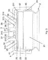
- the swivel nut 4 and valve body 3 can then be screwed as a cap on said top portion of the container using the external threading 24 of the top portion of the container 2 and the internal threading 45 of the swivel nut 4, thereby obtaining the system of container and cap shown in Figure 3 .
- the sealing portion 33 of the valve body 3 is clamped between the top end, here the inward extending portion 25 of the top portion 21, of the container and the clamping portion 41 of the swivel nut 4, thereby sealing the top portion 21 of the container so as to prevent leakage from the aperture 26 of the container underneath said sealing portion 23 of the valve body in between the swivel nut 4 and container 2 to the exterior of the container.
- the downward protrusions 311 at the lower outer edge of the sealing portion 33 provide additional sealing capacity to further prevent leakage.
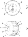
- the fluid withdrawal portion 31 comprises a first passage 37 and a second passage 38 extending from the top surface 34 to the bottom surface 39 of the valve body.
- the first passage 37 comprises at its lower end a first cross-slit valve 312, the second passage 38 at its lower end a second cross-slit valve 313, most clearly shown in Figure 2 .
- the two slits of each cross-slit valve cross in the center of the valve, thereby forming four valve sections.
- the slit valves 312,313 are embodied as aeration valves, that is, they open in response to an underpressure inside the container 2 with respect to the ambient pressure.
- the first passage 37 is adapted to receive a first tapered syringe tip of a first syringe in that said first tip is insertable into said first passage 37 from the top surface 34 of the valve body and in that the first passage 37 seals around said first tip when said first tip has been inserted into the first passage 37.
- the second passage 38 is adapted to receive a second tapered syringe tip of a second syringe in that said second tip is insertable into said second passage 38 from the top surface 34 of the valve body and in that the second passage 38 seals around said second tip when said tip has been inserted into the second passage 38.
- the first passage 37 is wider than the second passage 38, so that the first passage 37 is adapted to receive a tapered syringe tip with a larger diameter than the tapered syringe tip to which the second passage 38 is adapted.
- each cross-slit valve When none of the cross-slit valves 312,313 are actually forced open, e.g. by introduction of a syringe tip into the respective passage, each cross-slit valve will effectively seal or close its passage, so as to seal the container from the ambient.
- the container 2 with cap 1, said container comprising a fluid, can in this situation be turned upside down without any leakage of said fluid through the valves 312, 313.
- the lower surface 39 of the valve body comprises a receding surface portion 315 at the lower surface of the central fluid withdrawal portion, so as to form a recess 314 in the valve body relative to a surrounding region of the lower surface 39.
- the passages 37, 38 with cross-slit valves 312,313 end in the recessed area 314 of the lower surface 39 of the valve body 3.
- first cross-slit valve 312 and the second cross-slit valve 313 are both dome-shaped, as is apparent from figure 3 , with the dome being directed towards the inside of the container.
- the cross-slit valves 312, 313 are arranged at the lowermost end of the respective passage, so that here the convex surface of the dome-shape of each of the cross-slit valves 312, 313 forms part of the bottom surface 39 of the cross-slit valve.
- the passages 37, 38 above the cross-slit valve 312, 313 are conical, widening towards the top surface of the valve body, as preferred with a taper that corresponds to the taper of the syringe tip that is to be introduced into the passage.
- the taper is a 6% taper as is known in the field of syringes as a Luer taper.
- the tapering extends of the majority of the length of each passage, e.g. with the exception of a small entry bevel at the top surface.
- the slits in the valves 312, 313 extend over the entire diameter of the dome-shape, approximately corresponding to the narrowest width of the lower end of the respective passage 37, 38.
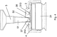
- Figure 4 shows an end portion of a first syringe 5 that is provided with a first tapered tip, here a first catheter tip 51.
- the first passage 37 of said valve body 3 is adapted to receive said first catheter syringe tip 51.
- the tip 51 is insertable into the first passage 37 of said valve body 3 from the top surface 34 thereof.
- the top section of said first tip 51 here is forced into the first cross-slit valve.
- the first passage 37 seals around said first catheter tip 51 when said top section 52 of said first catheter tip has been forced into the first cross-slit valve 312 and said first catheter tip 51 extends through the entire first passage 37.
- the first catheter tip 51 exerts a mechanical pressure onto the top surface of the first cross-slit valve 312 at the bottom of said first passage 37, upon which the valve sections of said cross-slit valve 312 bend downward and outward, so that said top section 52 of said first catheter tip 51 is forced into and through said cross-slit valve 312, so that said tip 51 extends through the entire first passage 37.
- valve body With the syringe tip 51 extending through the entire first passage 37, the valve body seals around the first catheter tip 51 of the first syringe 5.
- Fluid in the container 2 can now be drawn from said container by means of said syringe, and enter into the syringe 5 via the first catheter tip 51 thereof.
- the second cross-slit valve 313 which is at the same time not being forced open by a syringe tip, opens in response to said underpressure so as act as an aeration valve and to provide ambient air to said container, thereby removing said underpressure.
- the second cross-slit valve 313 allows to aerate said container 2 when fluid is withdrawn via a syringe tip inserted into the other passage of the valve body. In practice the aeration will take place in minute opening events of the respective valve.
- the user can retract the first tapered syringe tip, here catheter tip 51, from the first passage 37, and the first cross-slit valve 37 will then, due to its elasticity, automatically close and seal the first passage 37.
- the second cross-slit valve 313 will also automatically close and seal the second passage 38.
- the cap 1 seals the container 2 from the ambient.
- the first valve and second valve 312, 313 are embodied so that they will both act as a withdrawal valve as well as an aeration valve.
- a second syringe 6 with a second tapered syringe tip, here a Luer slip syringe tip, 61 may be used to withdraw fluid from the container 2 via the other passage 38.
- the second passage 38 of the valve body 3 is adapted to receive said second Luer slip syringe tip 61 in that a top section 62 of said Luer slip syringe tip 61 can be forced into and possibly through the second cross-slit valve 313 and in that the second passage 38 seals around said second Luer slip tip 61 when said top section 62 of said second Luer slip tip 61 opens the second cross-slit valve 313 and said second Luer slip tip 61 extends through the entire second passage 38.
- Said second tip 62 can be inserted into the second passage 38 from the top surface 34 of the valve body 3.
- the second tip 61 exerts mechanical pressure onto the top surface of the second cross-slit valve 313, upon which the valve sections of said cross-slit valve 313 bend downward and outward, so that said a top section 62 of the second tip 61 is forced into and possibly through said cross-slit valve 313, so that said tip 61 extends through the entire second passage 38.
- the second passage 38 is further adapted to receive said second Luer slip syringe tip 61 in that the valve body surface delimiting the second passage 38 has a conical surface with a taper the same or slightly smaller than the Luer taper and with a diameter the same or slightly smaller than, but similar to, the second diameter of the Luer slip syringe tip 61, so as to radially seal around said Luer slip syringe tip 61.
- the second passage 38 seals, e.g. radially seals, around the second Luer taper slip fitting tip 61 of the first syringe 6. Fluid in the container 2 can now be drawn from said container to said second syringe 6 via the second Luer taper slip fitting tip 61 thereof. Upon withdrawal of fluid from said container through said second passage 38 the first cross-slit valve 312 allows to aerate the container.
- the Luer taper syringe tip may be placed centrally on the syringe, giving the central Luer slip syringe tip 61 shown in Figure 5 , but may also be placed off-center, giving the eccentric Luer slip syringe tip 61 of Figure 6 .
- the cap may also comprise two or more passages that adapted to the same type of tapered syringe tip, e.g. each of the two passages adapted to receive a Luer slip syringe tip with the same taper angle. These passages adapted to receive the same type of tapered syringe tip may also be adapted to receive the same type of syringe tip with the same diameter, e.g. two Luer slip syringe tips with the same taper and the same diameter.
- Such an embodiment with two identical passages 37,38 adapted to receive Luer taper slip syringe tips is shown in Figure 7 .
- an embodiment with two identical passages 37,38 both adapted to receive catheter syringe tips, said catheter syringe tips having the same taper and diameter is shown in Figure 8 .
- FIG. 9 and 10 shows a cap with two identical passages 37,38, that are both adapted to receive both a catheter syringe tip 51 and a Luer slip tip 61.
- the passages 37,38 extend through the valve body and comprise cross-slit valves 312,313 embodied as aeration valves as described in the foregoing.
- the first passage 37 comprises at the lowermost end thereof a radial protrusion 371 into the first passage 37, said first protrusion 371 provided in the lower end of said first passage 37 and creating a first constriction or shoulder 372 in the first passage.
- the first cross-slit valve 312 is provided within said constriction 372.
- said first cross-slit valve 312 may also be provided below said constriction or shoulder 372.
- the first passage 37 is adapted to receive a first catheter syringe tip 51 having a first diameter in that said first catheter tip 51 is insertable into the first passage 37 from the top surface 34 of the valve body 3 in that said first protrusion 371 limits the insertion of the catheter syringe tip 51 into the first passage 37, in that when the top 52 of said first catheter tip 52 is provided on said first protrusion 371 the first cross-slit valve 312 can be opened by the underpressure created through retraction of the plunger of a first syringe 5 onto which the first catheter syringe tip 51 is provided and that the first passage 37 seals around said first catheter tip 51 when said first catheter tip 51 has been provided on said first protrusion 371.
- the first passage 37 is further adapted to receive a first Luer slip syringe tip 61 having a first Luer slip tip diameter in that said first Luer slip syringe tip 61 is insertable into the first passage 37 from the top surface 34 of the valve body 3, in that said Luer slip tip is insertable into the first constriction 372 in the first passage 37, in that the first protrusion 371 seals around the first Luer slip syringe tip 37 when said Luer slip tip 61 has been inserted in the first constriction 372 and in that a top section 62 of said first Luer slip syringe tip can be forced through the first cross-slit valve 312 so as to extend through the entire first passage 37.
- the catheter tip 51 can only extend through a part of the passage, as it is limited by the first protrusion 371 as shown in Figure 9
- the Luer slip syringe tip 61 can be inserted into the same passage, into the constriction thereof and can extend through said entire passage, shown in Figure 10 for a Luer slip syringe tip 61 inserted in to the second passage 38.
- the second passage 38 is adapted to receive both a catheter syringe tip 51 and a Luer slip syringe tip 61, in a manner analogous to the first passage 37.
- said second passage 38 comprises a radial protrusion 381 into the second passage 38, said second protrusion 381 provided in the lower end of said second passage 38 and creating a second constriction 382 in the second passage 38.
- the height of the fluid withdrawal portion 31 may vary in different embodiments of the inventive cap 1.
- the height of the fluid withdrawal portion 31 may for instance be reduced, as is shown in Figure 11 , so as to provide a more compact cap 1. Note that although the height of the fluid withdrawal portion 31 is reduced, the fixation portion 32 is still provided with a groove 310, through which said valve body 3 is fixed to the swivel nut 4.
Applications Claiming Priority (2)
| Application Number | Priority Date | Filing Date | Title |
|---|---|---|---|
| NL2016005A NL2016005B1 (en) | 2015-12-22 | 2015-12-22 | Needleless syringe connector cap. |
| PCT/NL2016/050899 WO2017111584A1 (en) | 2015-12-22 | 2016-12-21 | Needleless syringe connector cap and container |
Publications (2)
| Publication Number | Publication Date |
|---|---|
| EP3393572A1 EP3393572A1 (en) | 2018-10-31 |
| EP3393572B1 true EP3393572B1 (en) | 2019-10-09 |
Family
ID=55949023
Family Applications (1)
| Application Number | Title | Priority Date | Filing Date |
|---|---|---|---|
| EP16825584.2A Active EP3393572B1 (en) | 2015-12-22 | 2016-12-21 | Needleless syringe connector cap and container |
Country Status (8)
| Country | Link |
|---|---|
| US (1) | US10905631B2 (nl) |
| EP (1) | EP3393572B1 (nl) |
| JP (1) | JP3219248U (nl) |
| CN (1) | CN209437879U (nl) |
| BR (1) | BR112018012795A2 (nl) |
| ES (1) | ES2761676T3 (nl) |
| NL (1) | NL2016005B1 (nl) |
| WO (1) | WO2017111584A1 (nl) |
Families Citing this family (3)
| Publication number | Priority date | Publication date | Assignee | Title |
|---|---|---|---|---|
| NL2026679B1 (nl) * | 2020-10-15 | 2022-06-14 | Scholle Ipn Ip Bv | Spouted pouch and a closure assembly |
| WO2022271578A1 (en) * | 2021-06-21 | 2022-12-29 | Vertice Pharma Llc | Adapter for clinical, medical and laboratory containers |
| KR102599494B1 (ko) * | 2021-06-23 | 2023-11-06 | 박선경 | 무침 주사기용 격발너트 |
Family Cites Families (12)
| Publication number | Priority date | Publication date | Assignee | Title |
|---|---|---|---|---|
| US4530525A (en) * | 1983-01-17 | 1985-07-23 | Hollister Incorporated | Access port forming device and method |
| JP2002306610A (ja) | 2001-02-09 | 2002-10-22 | Fukai Kogyo Kk | 薬液等注入抽出口用シール弁 |
| DE10127823C1 (de) * | 2001-06-07 | 2002-08-22 | West Pharm Serv Drug Res Ltd | Verschluss für eine Medikamentenflasche sowie Verfahren zu dessen Herstellung |
| US20030018305A1 (en) * | 2001-07-17 | 2003-01-23 | Ming-Hsiung Tsai | Needleless vascular infusion port apparatus |
| US8562583B2 (en) * | 2002-03-26 | 2013-10-22 | Carmel Pharma Ab | Method and assembly for fluid transfer and drug containment in an infusion system |
| DE10348016B4 (de) * | 2003-10-15 | 2007-05-03 | Fresenius Kabi Deutschland Gmbh | Konnektor für medizinische Flüssigkeiten enthaltende Verpackungen und Verpackung für medizinische Flüssigkeiten |
| DE102004051300C5 (de) * | 2004-10-20 | 2013-01-24 | Fresenius Kabi Deutschland Gmbh | Verschlusskappe für mit medizinischen Flüssigkeiten befüllte Behältnisse |
| US7717897B2 (en) * | 2004-12-23 | 2010-05-18 | Hospira, Inc. | Medical fluid container with concave side weld |
| DE102007005407A1 (de) * | 2007-02-03 | 2008-08-07 | Fresenius Kabi Deutschland Gmbh | Verschlusskappe für ein Behältnis zur Aufnahme von medizinischen Flüssigkeiten und Behältnis zur Aufnahme von medizinischen Flüssigkeiten |
| DE102008060864A1 (de) * | 2008-12-09 | 2010-06-10 | Fresenius Kabi Deutschland Gmbh | Verschlusskappe für Behältnisse zur Aufnahme von medizinischen Flüssigkeiten und Behältnis zur Aufnahme von medizinischen Flüssigkeiten |
| EP2359799A1 (de) * | 2010-02-16 | 2011-08-24 | Fresenius Kabi Deutschland GmbH | Verschlusskappe für ein Behältnis zur Aufnahme von medizinischen Flüssigkeiten und Behältnis |
| AU2015215683B2 (en) * | 2014-02-07 | 2019-08-22 | Industrie Borla S.P.A. | Access device for containers of fluidizable substances |
-
2015
- 2015-12-22 NL NL2016005A patent/NL2016005B1/en not_active IP Right Cessation
-
2016
- 2016-12-21 ES ES16825584T patent/ES2761676T3/es active Active
- 2016-12-21 CN CN201690001565.4U patent/CN209437879U/zh active Active
- 2016-12-21 JP JP2018600073U patent/JP3219248U/ja active Active
- 2016-12-21 BR BR112018012795A patent/BR112018012795A2/pt not_active Application Discontinuation
- 2016-12-21 EP EP16825584.2A patent/EP3393572B1/en active Active
- 2016-12-21 US US16/064,504 patent/US10905631B2/en active Active
- 2016-12-21 WO PCT/NL2016/050899 patent/WO2017111584A1/en active Application Filing
Non-Patent Citations (1)
| Title |
|---|
| None * |
Also Published As
| Publication number | Publication date |
|---|---|
| EP3393572A1 (en) | 2018-10-31 |
| NL2016005B1 (en) | 2017-07-03 |
| JP3219248U (ja) | 2018-12-13 |
| US10905631B2 (en) | 2021-02-02 |
| BR112018012795A2 (pt) | 2018-12-04 |
| CN209437879U (zh) | 2019-09-27 |
| WO2017111584A1 (en) | 2017-06-29 |
| US20190000716A1 (en) | 2019-01-03 |
| ES2761676T3 (es) | 2020-05-20 |
Similar Documents
| Publication | Publication Date | Title |
|---|---|---|
| US20220288258A1 (en) | Caps to provide a physical barrier to an access site of a medical connector | |
| US11173007B2 (en) | Packaging sleeve for medical purposes | |
| US5464111A (en) | Closure for medication container | |
| ES2252828T3 (es) | Elemento penetrador para conjunto de tapa para recipiente y procedimiento para su fabricacion. | |
| KR101160278B1 (ko) | 의학용 액체를 함유하는 패키지를 위한 컨넥터와 의학용 액체를 함유하는 패키지 | |
| US20080009822A1 (en) | Needleless access vial | |
| US20050159724A1 (en) | Needleless access vial | |
| JP5204117B2 (ja) | 蓋及び分注システム | |
| EP3393572B1 (en) | Needleless syringe connector cap and container | |
| US20120078215A1 (en) | Two-piece vial transfer needle assembly | |
| JP2003528696A (ja) | 容器を医療装置に接続できるハウジング | |
| EP3269418A1 (en) | Tip cap assembly, medical injection system and process for producing a medical injection system | |
| EP0686123A1 (en) | CAP FOR MEDICAL CONTAINER | |
| NO301453B1 (no) | Enhetsdose-beholder | |
| EP3753544B1 (en) | Vial assembly with luer fitting | |
| JP3618744B2 (ja) | 鈍先差込み装置用の薄肉ダイアフラム・ストッパ | |
| US20190209435A1 (en) | Container for a medical liquid | |
| JP4056746B2 (ja) | 注射器接続ポート | |
| AU3434002A (en) | Container cap assembly having an enclosed penetrator |
Legal Events
| Date | Code | Title | Description |
|---|---|---|---|
| STAA | Information on the status of an ep patent application or granted ep patent |
Free format text: STATUS: UNKNOWN |
|
| STAA | Information on the status of an ep patent application or granted ep patent |
Free format text: STATUS: THE INTERNATIONAL PUBLICATION HAS BEEN MADE |
|
| PUAI | Public reference made under article 153(3) epc to a published international application that has entered the european phase |
Free format text: ORIGINAL CODE: 0009012 |
|
| STAA | Information on the status of an ep patent application or granted ep patent |
Free format text: STATUS: REQUEST FOR EXAMINATION WAS MADE |
|
| 17P | Request for examination filed |
Effective date: 20180703 |
|
| AK | Designated contracting states |
Kind code of ref document: A1 Designated state(s): AL AT BE BG CH CY CZ DE DK EE ES FI FR GB GR HR HU IE IS IT LI LT LU LV MC MK MT NL NO PL PT RO RS SE SI SK SM TR |
|
| AX | Request for extension of the european patent |
Extension state: BA ME |
|
| DAV | Request for validation of the european patent (deleted) | ||
| DAX | Request for extension of the european patent (deleted) | ||
| REG | Reference to a national code |
Ref country code: DE Ref legal event code: R079 Ref document number: 602016022315 Country of ref document: DE Free format text: PREVIOUS MAIN CLASS: A61M0039040000 Ipc: A61J0001200000 |
|
| GRAP | Despatch of communication of intention to grant a patent |
Free format text: ORIGINAL CODE: EPIDOSNIGR1 |
|
| STAA | Information on the status of an ep patent application or granted ep patent |
Free format text: STATUS: GRANT OF PATENT IS INTENDED |
|
| RIC1 | Information provided on ipc code assigned before grant |
Ipc: A61M 39/02 20060101ALI20190408BHEP Ipc: B65D 51/00 20060101ALI20190408BHEP Ipc: A61M 39/00 20060101ALI20190408BHEP Ipc: A61M 39/20 20060101ALI20190408BHEP Ipc: A61J 1/20 20060101AFI20190408BHEP Ipc: A61J 1/14 20060101ALI20190408BHEP Ipc: A61M 39/04 20060101ALI20190408BHEP Ipc: A61M 39/26 20060101ALI20190408BHEP |
|
| INTG | Intention to grant announced |
Effective date: 20190510 |
|
| GRAS | Grant fee paid |
Free format text: ORIGINAL CODE: EPIDOSNIGR3 |
|
| GRAA | (expected) grant |
Free format text: ORIGINAL CODE: 0009210 |
|
| STAA | Information on the status of an ep patent application or granted ep patent |
Free format text: STATUS: THE PATENT HAS BEEN GRANTED |
|
| AK | Designated contracting states |
Kind code of ref document: B1 Designated state(s): AL AT BE BG CH CY CZ DE DK EE ES FI FR GB GR HR HU IE IS IT LI LT LU LV MC MK MT NL NO PL PT RO RS SE SI SK SM TR |
|
| REG | Reference to a national code |
Ref country code: GB Ref legal event code: FG4D |
|
| REG | Reference to a national code |
Ref country code: CH Ref legal event code: EP |
|
| REG | Reference to a national code |
Ref country code: IE Ref legal event code: FG4D |
|
| REG | Reference to a national code |
Ref country code: DE Ref legal event code: R096 Ref document number: 602016022315 Country of ref document: DE |
|
| REG | Reference to a national code |
Ref country code: AT Ref legal event code: REF Ref document number: 1187950 Country of ref document: AT Kind code of ref document: T Effective date: 20191115 |
|
| REG | Reference to a national code |
Ref country code: NL Ref legal event code: FP |
|
| REG | Reference to a national code |
Ref country code: LT Ref legal event code: MG4D |
|
| REG | Reference to a national code |
Ref country code: AT Ref legal event code: MK05 Ref document number: 1187950 Country of ref document: AT Kind code of ref document: T Effective date: 20191009 |
|
| PG25 | Lapsed in a contracting state [announced via postgrant information from national office to epo] |
Ref country code: FI Free format text: LAPSE BECAUSE OF FAILURE TO SUBMIT A TRANSLATION OF THE DESCRIPTION OR TO PAY THE FEE WITHIN THE PRESCRIBED TIME-LIMIT Effective date: 20191009 Ref country code: LT Free format text: LAPSE BECAUSE OF FAILURE TO SUBMIT A TRANSLATION OF THE DESCRIPTION OR TO PAY THE FEE WITHIN THE PRESCRIBED TIME-LIMIT Effective date: 20191009 Ref country code: BG Free format text: LAPSE BECAUSE OF FAILURE TO SUBMIT A TRANSLATION OF THE DESCRIPTION OR TO PAY THE FEE WITHIN THE PRESCRIBED TIME-LIMIT Effective date: 20200109 Ref country code: PL Free format text: LAPSE BECAUSE OF FAILURE TO SUBMIT A TRANSLATION OF THE DESCRIPTION OR TO PAY THE FEE WITHIN THE PRESCRIBED TIME-LIMIT Effective date: 20191009 Ref country code: SE Free format text: LAPSE BECAUSE OF FAILURE TO SUBMIT A TRANSLATION OF THE DESCRIPTION OR TO PAY THE FEE WITHIN THE PRESCRIBED TIME-LIMIT Effective date: 20191009 Ref country code: LV Free format text: LAPSE BECAUSE OF FAILURE TO SUBMIT A TRANSLATION OF THE DESCRIPTION OR TO PAY THE FEE WITHIN THE PRESCRIBED TIME-LIMIT Effective date: 20191009 Ref country code: NO Free format text: LAPSE BECAUSE OF FAILURE TO SUBMIT A TRANSLATION OF THE DESCRIPTION OR TO PAY THE FEE WITHIN THE PRESCRIBED TIME-LIMIT Effective date: 20200109 Ref country code: PT Free format text: LAPSE BECAUSE OF FAILURE TO SUBMIT A TRANSLATION OF THE DESCRIPTION OR TO PAY THE FEE WITHIN THE PRESCRIBED TIME-LIMIT Effective date: 20200210 Ref country code: GR Free format text: LAPSE BECAUSE OF FAILURE TO SUBMIT A TRANSLATION OF THE DESCRIPTION OR TO PAY THE FEE WITHIN THE PRESCRIBED TIME-LIMIT Effective date: 20200110 Ref country code: AT Free format text: LAPSE BECAUSE OF FAILURE TO SUBMIT A TRANSLATION OF THE DESCRIPTION OR TO PAY THE FEE WITHIN THE PRESCRIBED TIME-LIMIT Effective date: 20191009 |
|
| REG | Reference to a national code |
Ref country code: ES Ref legal event code: FG2A Ref document number: 2761676 Country of ref document: ES Kind code of ref document: T3 Effective date: 20200520 |
|
| PG25 | Lapsed in a contracting state [announced via postgrant information from national office to epo] |
Ref country code: IS Free format text: LAPSE BECAUSE OF FAILURE TO SUBMIT A TRANSLATION OF THE DESCRIPTION OR TO PAY THE FEE WITHIN THE PRESCRIBED TIME-LIMIT Effective date: 20200224 Ref country code: HR Free format text: LAPSE BECAUSE OF FAILURE TO SUBMIT A TRANSLATION OF THE DESCRIPTION OR TO PAY THE FEE WITHIN THE PRESCRIBED TIME-LIMIT Effective date: 20191009 Ref country code: RS Free format text: LAPSE BECAUSE OF FAILURE TO SUBMIT A TRANSLATION OF THE DESCRIPTION OR TO PAY THE FEE WITHIN THE PRESCRIBED TIME-LIMIT Effective date: 20191009 |
|
| PG25 | Lapsed in a contracting state [announced via postgrant information from national office to epo] |
Ref country code: AL Free format text: LAPSE BECAUSE OF FAILURE TO SUBMIT A TRANSLATION OF THE DESCRIPTION OR TO PAY THE FEE WITHIN THE PRESCRIBED TIME-LIMIT Effective date: 20191009 |
|
| REG | Reference to a national code |
Ref country code: DE Ref legal event code: R097 Ref document number: 602016022315 Country of ref document: DE |
|
| PG2D | Information on lapse in contracting state deleted |
Ref country code: IS |
|
| PG25 | Lapsed in a contracting state [announced via postgrant information from national office to epo] |
Ref country code: EE Free format text: LAPSE BECAUSE OF FAILURE TO SUBMIT A TRANSLATION OF THE DESCRIPTION OR TO PAY THE FEE WITHIN THE PRESCRIBED TIME-LIMIT Effective date: 20191009 Ref country code: DK Free format text: LAPSE BECAUSE OF FAILURE TO SUBMIT A TRANSLATION OF THE DESCRIPTION OR TO PAY THE FEE WITHIN THE PRESCRIBED TIME-LIMIT Effective date: 20191009 Ref country code: CZ Free format text: LAPSE BECAUSE OF FAILURE TO SUBMIT A TRANSLATION OF THE DESCRIPTION OR TO PAY THE FEE WITHIN THE PRESCRIBED TIME-LIMIT Effective date: 20191009 Ref country code: RO Free format text: LAPSE BECAUSE OF FAILURE TO SUBMIT A TRANSLATION OF THE DESCRIPTION OR TO PAY THE FEE WITHIN THE PRESCRIBED TIME-LIMIT Effective date: 20191009 Ref country code: IS Free format text: LAPSE BECAUSE OF FAILURE TO SUBMIT A TRANSLATION OF THE DESCRIPTION OR TO PAY THE FEE WITHIN THE PRESCRIBED TIME-LIMIT Effective date: 20200209 |
|
| REG | Reference to a national code |
Ref country code: CH Ref legal event code: PL |
|
| PLBE | No opposition filed within time limit |
Free format text: ORIGINAL CODE: 0009261 |
|
| STAA | Information on the status of an ep patent application or granted ep patent |
Free format text: STATUS: NO OPPOSITION FILED WITHIN TIME LIMIT |
|
| REG | Reference to a national code |
Ref country code: BE Ref legal event code: MM Effective date: 20191231 |
|
| PG25 | Lapsed in a contracting state [announced via postgrant information from national office to epo] |
Ref country code: MC Free format text: LAPSE BECAUSE OF FAILURE TO SUBMIT A TRANSLATION OF THE DESCRIPTION OR TO PAY THE FEE WITHIN THE PRESCRIBED TIME-LIMIT Effective date: 20191009 Ref country code: SM Free format text: LAPSE BECAUSE OF FAILURE TO SUBMIT A TRANSLATION OF THE DESCRIPTION OR TO PAY THE FEE WITHIN THE PRESCRIBED TIME-LIMIT Effective date: 20191009 Ref country code: SK Free format text: LAPSE BECAUSE OF FAILURE TO SUBMIT A TRANSLATION OF THE DESCRIPTION OR TO PAY THE FEE WITHIN THE PRESCRIBED TIME-LIMIT Effective date: 20191009 |
|
| 26N | No opposition filed |
Effective date: 20200710 |
|
| PG25 | Lapsed in a contracting state [announced via postgrant information from national office to epo] |
Ref country code: IE Free format text: LAPSE BECAUSE OF NON-PAYMENT OF DUE FEES Effective date: 20191221 Ref country code: LU Free format text: LAPSE BECAUSE OF NON-PAYMENT OF DUE FEES Effective date: 20191221 |
|
| PG25 | Lapsed in a contracting state [announced via postgrant information from national office to epo] |
Ref country code: LI Free format text: LAPSE BECAUSE OF NON-PAYMENT OF DUE FEES Effective date: 20191231 Ref country code: CH Free format text: LAPSE BECAUSE OF NON-PAYMENT OF DUE FEES Effective date: 20191231 Ref country code: SI Free format text: LAPSE BECAUSE OF FAILURE TO SUBMIT A TRANSLATION OF THE DESCRIPTION OR TO PAY THE FEE WITHIN THE PRESCRIBED TIME-LIMIT Effective date: 20191009 Ref country code: BE Free format text: LAPSE BECAUSE OF NON-PAYMENT OF DUE FEES Effective date: 20191231 |
|
| PG25 | Lapsed in a contracting state [announced via postgrant information from national office to epo] |
Ref country code: CY Free format text: LAPSE BECAUSE OF FAILURE TO SUBMIT A TRANSLATION OF THE DESCRIPTION OR TO PAY THE FEE WITHIN THE PRESCRIBED TIME-LIMIT Effective date: 20191009 |
|
| PG25 | Lapsed in a contracting state [announced via postgrant information from national office to epo] |
Ref country code: MT Free format text: LAPSE BECAUSE OF FAILURE TO SUBMIT A TRANSLATION OF THE DESCRIPTION OR TO PAY THE FEE WITHIN THE PRESCRIBED TIME-LIMIT Effective date: 20191009 Ref country code: HU Free format text: LAPSE BECAUSE OF FAILURE TO SUBMIT A TRANSLATION OF THE DESCRIPTION OR TO PAY THE FEE WITHIN THE PRESCRIBED TIME-LIMIT; INVALID AB INITIO Effective date: 20161221 |
|
| PG25 | Lapsed in a contracting state [announced via postgrant information from national office to epo] |
Ref country code: TR Free format text: LAPSE BECAUSE OF FAILURE TO SUBMIT A TRANSLATION OF THE DESCRIPTION OR TO PAY THE FEE WITHIN THE PRESCRIBED TIME-LIMIT Effective date: 20191009 |
|
| PGFP | Annual fee paid to national office [announced via postgrant information from national office to epo] |
Ref country code: ES Payment date: 20220106 Year of fee payment: 6 |
|
| REG | Reference to a national code |
Ref country code: DE Ref legal event code: R081 Ref document number: 602016022315 Country of ref document: DE Owner name: CURA PACKAGING B.V., NL Free format text: FORMER OWNER: SCHOLLE IPN IP B.V., TILBURG, NL |
|
| REG | Reference to a national code |
Ref country code: NL Ref legal event code: PD Owner name: CURA PACKAGING B.V.; NL Free format text: DETAILS ASSIGNMENT: CHANGE OF OWNER(S), ASSIGNMENT; FORMER OWNER NAME: SCHOLLE IPN IP B.V. Effective date: 20220610 |
|
| PG25 | Lapsed in a contracting state [announced via postgrant information from national office to epo] |
Ref country code: MK Free format text: LAPSE BECAUSE OF FAILURE TO SUBMIT A TRANSLATION OF THE DESCRIPTION OR TO PAY THE FEE WITHIN THE PRESCRIBED TIME-LIMIT Effective date: 20191009 |
|
| REG | Reference to a national code |
Ref country code: GB Ref legal event code: 732E Free format text: REGISTERED BETWEEN 20220630 AND 20220706 |
|
| REG | Reference to a national code |
Ref country code: ES Ref legal event code: PC2A Owner name: CURA PACKAGING B.V. Effective date: 20221004 |
|
| PGFP | Annual fee paid to national office [announced via postgrant information from national office to epo] |
Ref country code: IT Payment date: 20221220 Year of fee payment: 7 |
|
| P01 | Opt-out of the competence of the unified patent court (upc) registered |
Effective date: 20230519 |
|
| PGFP | Annual fee paid to national office [announced via postgrant information from national office to epo] |
Ref country code: GB Payment date: 20231220 Year of fee payment: 8 |
|
| PGFP | Annual fee paid to national office [announced via postgrant information from national office to epo] |
Ref country code: NL Payment date: 20231221 Year of fee payment: 8 Ref country code: FR Payment date: 20231219 Year of fee payment: 8 Ref country code: DE Payment date: 20231214 Year of fee payment: 8 |
|
| REG | Reference to a national code |
Ref country code: ES Ref legal event code: FD2A Effective date: 20240201 |
|
| PG25 | Lapsed in a contracting state [announced via postgrant information from national office to epo] |
Ref country code: ES Free format text: LAPSE BECAUSE OF NON-PAYMENT OF DUE FEES Effective date: 20221222 |