EP3392604B1 - Missile pourvu d'une coiffe séparable comprenant au moins une coque éjectable coopérant avec un élément de support - Google Patents
Missile pourvu d'une coiffe séparable comprenant au moins une coque éjectable coopérant avec un élément de support Download PDFInfo
- Publication number
- EP3392604B1 EP3392604B1 EP18290012.6A EP18290012A EP3392604B1 EP 3392604 B1 EP3392604 B1 EP 3392604B1 EP 18290012 A EP18290012 A EP 18290012A EP 3392604 B1 EP3392604 B1 EP 3392604B1
- Authority
- EP
- European Patent Office
- Prior art keywords
- longitudinal axis
- missile
- shell
- angle
- rear end
- Prior art date
- Legal status (The legal status is an assumption and is not a legal conclusion. Google has not performed a legal analysis and makes no representation as to the accuracy of the status listed.)
- Active
Links
Images

Classifications
-
- F—MECHANICAL ENGINEERING; LIGHTING; HEATING; WEAPONS; BLASTING
- F42—AMMUNITION; BLASTING
- F42B—EXPLOSIVE CHARGES, e.g. FOR BLASTING, FIREWORKS, AMMUNITION
- F42B10/00—Means for influencing, e.g. improving, the aerodynamic properties of projectiles or missiles; Arrangements on projectiles or missiles for stabilising, steering, range-reducing, range-increasing or fall-retarding
- F42B10/32—Range-reducing or range-increasing arrangements; Fall-retarding means
- F42B10/38—Range-increasing arrangements
- F42B10/42—Streamlined projectiles
- F42B10/46—Streamlined nose cones; Windshields; Radomes
-
- F—MECHANICAL ENGINEERING; LIGHTING; HEATING; WEAPONS; BLASTING
- F42—AMMUNITION; BLASTING
- F42B—EXPLOSIVE CHARGES, e.g. FOR BLASTING, FIREWORKS, AMMUNITION
- F42B10/00—Means for influencing, e.g. improving, the aerodynamic properties of projectiles or missiles; Arrangements on projectiles or missiles for stabilising, steering, range-reducing, range-increasing or fall-retarding
Definitions
- the present invention relates to a missile provided with at least one ejectable shell forming part of a releasable or separable protective cap.
- the present invention applies, more particularly although not exclusively, to a missile comprising at least one propellant stage which is intended to propel the missile and which can be separated from the latter, as well as a terminal vehicle which is arranged at the 'before this propulsive stage and which performs a terminal flight towards a target.
- a terminal vehicle comprises at least one sensor forming, for example, part of a seeker, which is sensitive to temperature.
- the present invention applies more particularly to a missile having a flight domain remaining in the atmosphere and which has kinematic performances making it possible to bring the terminal vehicle to supersonic speeds. At these high speeds, the surface temperature of the missile can reach several hundred degrees Celsius under the effect of the aerothermal flow, which can be detrimental for the behavior and performance of the structures, and of the electronic equipment and sensors present. Also, the missile is generally provided at the front with a protective cap, which generally comprises several individual shells and which is intended to thermally and mechanically protect the terminal vehicle.
- This protective cap, and at least some and preferably all of the shells, must be able to be removed at the appropriate time, in particular to allow the use of the sensor placed on the terminal vehicle in the terminal phase of the flight.
- the object of the present invention is to remedy this drawback. It relates to a missile provided with a body having a longitudinal axis called the main longitudinal axis and at least one separable cap, said cap comprising at least one ejectable shell, said shell being connected by a so-called rear end to a support element of the missile and being defined around a longitudinal axis said secondary longitudinal axis.
- said rim assembly comprises two edge sections in an arc of a circle, arranged symmetrically with respect to a longitudinal plane containing the main longitudinal axis, each of said edge sections being configured so that its orthogonal projection on said longitudinal plane has a rectilinear front edge forming with its rear edge an angle equal to said ejection angle, said rear edge being orthogonal to said main longitudinal axis.
- said rear end of the shell comprises, in thickness, a thinned rear part intended to be housed with contact in said housing, followed towards the front by a thickened part forming a shoulder allowing an auxiliary transverse contact. of the shell on the front edge of the flange assembly in the mounting position.
- said support element corresponds to a part of the body of the missile.
- said support element is an insert, suitable for being mounted on the body of the missile.
- the characteristics in particular of thickness are formed (preferably machined) directly in the rear end of the shell.
- said rear end is provided with an interface piece which is fixed to the rear of the shell.
- the missile comprises at least one controllable actuating device capable of generating a force capable of causing the hull to pivot from the mounting position to an ejection position in which the secondary longitudinal axis of the shell has an angle equal to the ejection angle with respect to said main longitudinal axis of the missile body.
- the missile comprises two complementary shells forming said cap, and an annular support piece formed by two identical support elements, each of said shells being connected via its rear end to one of said support elements of the support piece.
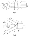
- FIGS. 1 and 2 schematically show an example of a missile to which the present invention applies, provided with a protective cap which is, respectively, in a position mounted on the missile and in an open position.
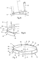
- the figure 3 shows the cap in an open position.
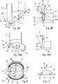
- the figures 4 to 11 represent different schematic views showing the maintenance and ejection of a cap shell relative to the missile, these figures 4 to 11 allowing to clearly highlight the main characteristics of the invention.
- the present invention applies to a missile 1 shown diagrammatically on the Figures 1 and 2 .
- the missile 1 is provided with a body 7, at least partially cylindrical, having a longitudinal axis XX called the main longitudinal axis.
- Missile 1 is provided at the front with a protective cap 2.
- This protective cap 2 (called “cap 2” below) comprises a plurality of shells 3 and 4, in this case two shells 3 and 4 in the examples considered in the description below.
- the front and rear adverbs are defined with respect to the direction of movement F of missile 1.
- the missile 1 comprises at least one propellant stage 5 which can be released (at the rear) and a terminal vehicle 6 which is arranged at the front (in the direction of movement F) of this propellant stage 5.
- such a flying terminal vehicle 6 comprises, in particular, at least one sensor 8 arranged at the front, for example forming part of a seeker and capable of being sensitive to temperature.
- the propulsion stage 5 and the terminal vehicle 6 which can be of any usual type, are not described further in the following description.
- the propulsion stage or stages 5 of such a missile 1 are intended for the propulsion of said missile 1, from firing to approaching a target (to be neutralized by missile 1).
- the terminal phase of the flight is, in turn, carried out autonomously by the terminal vehicle 6, which in particular uses the information from the on-board sensor 8, for example an optoelectronic sensor intended to aid in the detection of the target.
- the terminal vehicle 6 includes all the usual means (not described further), which are necessary to achieve this terminal flight.
- the cover 2 is released, after a separation of the different shells 3 and 4, by pivoting, as specified below, to release the terminal vehicle 6 (steering wheel) which then separates from the rest of the missile 1.
- the missile 1 is therefore provided at the front with a separable (or releasable) cap 2 which is intended, in particular, to thermally and mechanically protect the terminal vehicle 6.
- This protective cap 2 must however be able to be removed at the appropriate time, in particular to allow the use of the sensor 8 placed on the terminal vehicle 6 in the terminal phase of the flight.
- the cap 2 is mounted on the missile 1 in a so-called mounting (protective) position.
- the terminal vehicle 6 shown in dashes is mounted inside the cover 2.
- the shells 3 and 4 are in the process of separating, by being pivoted, as illustrated respectively by arrows a1 and a2, during a phase of opening or release of the cover 2.
- the release (or ejection) of the shells 3 and 4 and the pulse for generating the movements illustrated by the arrows a1 and a2 (away from the axis XX), can be generated by an appropriate actuating device 9, for example a pyrotechnic actuator preferably arranged at the front of the cover 2 (inside the latter), as shown diagrammatically in dashes on the figure 1 .
- the present invention is particularly well suited to a missile 1 having a flight domain remaining in the atmosphere and which has kinematic performance allowing the terminal vehicle 6 to be brought to hypersonic speeds. At these high speeds, the surface temperature of the missile 1 can reach several hundred degrees Celsius under the effect of the aerothermal flow, which requires providing an effective cap 2 to allow the holding and performance of structures, electronic equipment and on-board sensors.
- the present invention can be applied to a missile evolving in all cases of the flight domain (in and out of atmosphere) and for speeds going from subsonic to high supersonic / hypersonic.
- the cap 2 is connected by a rear end 2A to a support piece 10 of the missile 1, as shown in the figure 3 .
- the two shells 3 and 4 are each linked by their rear end 3A and 4A to a support element 11, 12 ( figures 4 and 7 ) forming part of the support piece 10.
- Each of these shells 3 and 4 is defined around a longitudinal axis called the secondary longitudinal axis LL, as shown in the figures 4 and 5 especially.
- the annular support piece 10 is formed from two identical support elements 11 and 12. Each of the shells 3 and 4 is therefore linked via its rear end 3A, 4A to one of said support elements 11 and 12.
- each support element 11, 12 has the shape of an arc of a circle centered on the main longitudinal axis XX and arranged in a plane P ( figure 2 ) which is orthogonal to said axis XX.
- the controllable actuating device 9 is capable of generating a force (illustrated by a double arrow E on the figures 2 and 3 ) likely to cause the shells 3 and 4 to pivot from the mounting position of the figure 1 to an ejection position, in which the secondary longitudinal axis LL of each shell 3, 4 has an angle equal to an angle called ejection ⁇ 0 with respect to said main longitudinal axis XX of the body 7 of the missile 1, as illustrated in the figure 5 for hull 3 and specified below.
- each support element 11, 12 is provided with a flange assembly 13 and a crown element 14.
- the flange assembly 13 and the crown element 14 each have an arc of a circle shape centered on the main longitudinal axis XX.
- the crown element 14 is arranged coaxially along the axis X-X, radially inside said rim assembly 13 so as to create between them a housing 15 in the form of an arc of a circle.
- the embodiment of the invention is described below for the shell 3.
- the embodiment is identical for the shell 4.
- This configuration of the support element 11, 12 combined with that of the rear end 3A, 3B of a shell 3, 4, or more generally the configuration of the support piece 10 combined with that of the rear end 2A of the cap 2, forms a system S for holding and ejection making it possible to maintain the cap 2 and allowing its ejection while controlling the angle of ejection.
- the ejection angle ⁇ 0 can in particular be adapted to the missile (type, size, etc.) considered and to the ejection conditions (altitude, atmosphere, trajectory of the missile, etc.) envisaged. This ejection angle ⁇ 0 can be controlled by tests. Although not exclusively, the ejection angle ⁇ 0 can for example be defined in a range of values from 6 ° to 15 °.
- said rim assembly 13 intended for a shell 3 or 4 comprises two rim sections 16 in an arc. These rim sections 16 are arranged symmetrically with respect to a longitudinal plane OXZ containing the main longitudinal axis XX.
- an OXYZ coordinate system has been represented, in which O represents the intersection of the axis XX with the plane P, OX is defined along the axis XX in the direction F, OY is such that the plane OXY corresponds substantially to a plane of separation between the shells 3 and 4, and OZ is such that the plane OXZ substantially forms a plane of symmetry for each of the shells 3 and 4.
- Each of said rim sections 16 is configured so that its orthogonal projection on said longitudinal plane OXZ has a straight front edge 17 forming with its rear edge 18 (straight) an angle ⁇ equal to said ejection angle ⁇ 0, as shown in the figure 11 .
- Two flange sections 16, one of which is intended for the shell 3 and the other for the shell 4 each form a flange piece 19, as shown in the figure 11 .
- the support piece 10 therefore comprises two flange pieces 19 of this type, which are systematically mounted with respect to the longitudinal plane OXZ, as shown on the figure 8 .
- the two flange pieces 19 are produced in a (single) piece in one piece.
- the support piece 10 comprises two crown elements 14, identical and symmetrical with respect to the OXY plane. These two crown elements 14 form a crown 20 ( figure 7 ) centered on the XX axis. This crown 20 is preferably an insert. It can also correspond to a part of the external surface of the terminal vehicle 6 as illustrated on the figure 8 .
- the rear end 3A of the shell 3 comprises, in thickness, a thinned rear portion 21 (of thickness E1) intended to be housed with contact in said housing 15, followed towards the front by a thickened part 22 (of thickness E2 greater than thickness E1) forming a shoulder 23 allowing an auxiliary transverse contact C4 of the shell 3 on the front edge 17 of the flange assembly 13 in the mounting position, as shown in the figure 9B .
- This shoulder 23 has a shape adapted to that of the front edges 17 of the two rim sections 16 associated.
- the rear end 3A of the shell 3 does not have a thinned part but only the thickened part 22 of thickness E2.
- the S system allows hulls 3 and 4 to be held as illustrated by arrows G on the figure 8 , and a pivoting of the shells 3 and 4 as illustrated by arrows H on this figure 8 .
- the hull 3 is pivoted without a hinge by simple contact at the level of a zone 25 ( figures 2 , 10A, 10B ) located near the intersection of the OZ axis with the shell 3.
- the support part 10 corresponds to a part of the body 7 of the missile 1.
- the support part 10 is an attached part, capable of being mounted (and fixed) on the body 7 of the missile 1.
- the characteristics in particular of thickness (E1 and E2) are formed (preferably machined) directly in the rear end 3A, 4A of the shell 3, 4.
- the rear end 3A, 4A of each shell 3, 4, having these characteristics is provided with an interface piece which is fixed to the rear of the shell 3, 4.
- the operation of the holding and ejection system S (with control over the ejection angle), as described above, is as follows, during ejection.
- the actuating device 9 is activated to generate forces illustrated by the double arrow E (on the figures 2 and 3 ) in order to rotate the shells 3 and 4 in the directions illustrated by the arrows a1 and a2 ( figure 2 ). Thanks to the system S, the shells 3 and 4 are held on the support piece 10 until the pivot angles a1 and a2 reach the value e0 of ejection angle. At this pivoting position, the shells 3 and 4 are no longer held by the support piece 10 and are released from the missile 1, from which they move away, which results in the release of the cover 2.
- the ejection angle is a paramount parameter which is difficult to control with the usual solutions, in particular as a function of the ejection conditions (altitude, atmosphere, trajectory of the missile, etc.). Thanks to this control, we can ensure that the ejection does not damage the missile and does not disturb its terminal phase.
- the S system works in all cases of the flight range (in and out of the atmosphere) of a missile 1 and for speeds ranging from subsonic to high supersonic / hypersonic.
Landscapes
- Physics & Mathematics (AREA)
- Fluid Mechanics (AREA)
- Engineering & Computer Science (AREA)
- General Engineering & Computer Science (AREA)
- Aiming, Guidance, Guns With A Light Source, Armor, Camouflage, And Targets (AREA)
Priority Applications (1)
| Application Number | Priority Date | Filing Date | Title |
|---|---|---|---|
| PL18290012T PL3392604T3 (pl) | 2017-04-21 | 2018-02-19 | Pocisk wyposażony w oddzielany czepiec pocisku zawierający co najmniej jedną odrzucalną skorupę współpracującą z elementem nośnym |
Applications Claiming Priority (1)
| Application Number | Priority Date | Filing Date | Title |
|---|---|---|---|
| FR1700448A FR3065521B1 (fr) | 2017-04-21 | 2017-04-21 | Missile pourvu d'une coiffe separable comprenant au moins une coque ejectable cooperant avec un element de support |
Publications (2)
| Publication Number | Publication Date |
|---|---|
| EP3392604A1 EP3392604A1 (fr) | 2018-10-24 |
| EP3392604B1 true EP3392604B1 (fr) | 2020-01-29 |
Family
ID=59974474
Family Applications (1)
| Application Number | Title | Priority Date | Filing Date |
|---|---|---|---|
| EP18290012.6A Active EP3392604B1 (fr) | 2017-04-21 | 2018-02-19 | Missile pourvu d'une coiffe séparable comprenant au moins une coque éjectable coopérant avec un élément de support |
Country Status (8)
| Country | Link |
|---|---|
| US (1) | US10767968B2 (pl) |
| EP (1) | EP3392604B1 (pl) |
| JP (1) | JP7032431B2 (pl) |
| ES (1) | ES2775445T3 (pl) |
| FR (1) | FR3065521B1 (pl) |
| IL (1) | IL269761B2 (pl) |
| PL (1) | PL3392604T3 (pl) |
| WO (1) | WO2018193170A1 (pl) |
Families Citing this family (7)
| Publication number | Priority date | Publication date | Assignee | Title |
|---|---|---|---|---|
| JP7177919B2 (ja) * | 2019-04-26 | 2022-11-24 | 川崎重工業株式会社 | ノーズフェアリング |
| US11274907B2 (en) * | 2020-04-28 | 2022-03-15 | Raytheon Company | Shroud driven deployable flight surfaces and method |
| JP7446915B2 (ja) * | 2020-05-25 | 2024-03-11 | 三菱重工業株式会社 | 整流構造、飛翔体及び宇宙機 |
| CN114046694A (zh) * | 2021-11-03 | 2022-02-15 | 天津爱思达航天科技有限公司 | 复材壳体连接框加强结构 |
| CN114777576A (zh) * | 2022-04-08 | 2022-07-22 | 湖北航天技术研究院总体设计所 | 一种整流罩装置及旋转侧抛方法 |
| FI130682B1 (en) * | 2022-07-11 | 2024-01-16 | Raimo Hirvinen | Rocket stage, rocket and landing gear |
| US20240288253A1 (en) * | 2023-02-28 | 2024-08-29 | Joseph Peter Kolnik | Less lethal ammunition system |
Family Cites Families (18)
| Publication number | Priority date | Publication date | Assignee | Title |
|---|---|---|---|---|
| US3706281A (en) * | 1971-04-01 | 1972-12-19 | Nasa | Method and system for ejecting fairing sections from a rocket vehicle |
| JPS5640640Y2 (pl) * | 1972-03-21 | 1981-09-22 | ||
| JPH02267500A (ja) * | 1989-04-10 | 1990-11-01 | Mitsubishi Electric Corp | ミサイル用耐熱レドーム |
| US5263418A (en) * | 1992-01-24 | 1993-11-23 | Olin Corporation | Hollow point sabot bullet |
| JPH06313699A (ja) * | 1993-04-30 | 1994-11-08 | Mitsubishi Heavy Ind Ltd | レドーム装置 |
| US5479861A (en) * | 1994-01-03 | 1996-01-02 | Kinchin; Anthony E. | Projectile with sabot |
| JP3223171B2 (ja) * | 1998-12-24 | 2001-10-29 | 宇宙開発事業団 | ロケットフェアリングの分割構造および分割方法 |
| DE10240040A1 (de) * | 2002-08-27 | 2004-03-11 | BODENSEEWERK GERäTETECHNIK GMBH | Lenkflugkörper mit abwerfbarer Schutzkappe |
| US7082878B2 (en) * | 2003-07-01 | 2006-08-01 | Raytheon Company | Missile with multiple nosecones |
| US7549376B1 (en) * | 2005-07-15 | 2009-06-23 | The United States Of America As Represented By The Secretary Of The Army | Non-lethal projectile carrier |
| US8519312B1 (en) * | 2010-01-29 | 2013-08-27 | Raytheon Company | Missile with shroud that separates in flight |
| DE102010007064B4 (de) * | 2010-02-06 | 2012-03-29 | Diehl Bgt Defence Gmbh & Co. Kg | Flugkörperkopf und Verfahren zum Trennen einer Haube von einem Rumpf eines Flugkörpers |
| US8069791B1 (en) * | 2010-03-31 | 2011-12-06 | The United States Of America As Represented By The Secretary Of The Navy | Curvilinear sabot system |
| US8931738B2 (en) * | 2012-02-21 | 2015-01-13 | Raytheon Company | Releasable radome cover |
| US9587922B2 (en) * | 2013-04-12 | 2017-03-07 | Raytheon Company | Attack capability enhancing ballistic sabot |
| IL232381B (en) | 2014-04-30 | 2020-02-27 | Israel Aerospace Ind Ltd | Cover |
| FR3022885B1 (fr) * | 2014-06-25 | 2016-10-21 | Mbda France | Paroi structurante de missile, en particulier pour coiffe de protection thermique |
| FR3022995B1 (fr) * | 2014-06-25 | 2017-06-09 | Mbda France | Missile pourvu d'une coiffe de protection separable |
-
2017
- 2017-04-21 FR FR1700448A patent/FR3065521B1/fr not_active Expired - Fee Related
-
2018
- 2018-02-19 WO PCT/FR2018/000032 patent/WO2018193170A1/fr not_active Ceased
- 2018-02-19 PL PL18290012T patent/PL3392604T3/pl unknown
- 2018-02-19 IL IL269761A patent/IL269761B2/en unknown
- 2018-02-19 US US16/500,528 patent/US10767968B2/en active Active
- 2018-02-19 EP EP18290012.6A patent/EP3392604B1/fr active Active
- 2018-02-19 ES ES18290012T patent/ES2775445T3/es active Active
- 2018-02-19 JP JP2019554627A patent/JP7032431B2/ja active Active
Non-Patent Citations (1)
| Title |
|---|
| None * |
Also Published As
| Publication number | Publication date |
|---|---|
| US20200049474A1 (en) | 2020-02-13 |
| JP2020517881A (ja) | 2020-06-18 |
| IL269761B1 (en) | 2023-12-01 |
| US10767968B2 (en) | 2020-09-08 |
| WO2018193170A1 (fr) | 2018-10-25 |
| JP7032431B2 (ja) | 2022-03-08 |
| EP3392604A1 (fr) | 2018-10-24 |
| IL269761A (en) | 2019-11-28 |
| IL269761B2 (en) | 2024-04-01 |
| ES2775445T3 (es) | 2020-07-27 |
| FR3065521A1 (fr) | 2018-10-26 |
| PL3392604T3 (pl) | 2020-06-15 |
| FR3065521B1 (fr) | 2019-06-28 |
Similar Documents
| Publication | Publication Date | Title |
|---|---|---|
| EP3392604B1 (fr) | Missile pourvu d'une coiffe séparable comprenant au moins une coque éjectable coopérant avec un élément de support | |
| EP2960618B1 (fr) | Missile pourvu d'une coiffe de protection séparable | |
| WO2009068488A1 (fr) | Dispositif d'arrière corps d'engin spatial | |
| EP4251517B1 (fr) | Systeme de transport spatial reutilisable | |
| FR2578640A1 (fr) | Missile a empennage surcalibre | |
| EP3396300B1 (fr) | Dispositif d'actionnement pour l'éjection d'au moins une partie amovible de missile, en particulier d'une coiffe | |
| EP0488872B1 (fr) | Dispositif d'assujettissement temporaire d'un objet à un support à douille de retenue monobloc | |
| EP0367815B1 (fr) | Dispositif de separation de freinage aerodynamique d'un corps | |
| EP2189373B1 (fr) | Stabilisateur pour stabiliser les disques d'un puits de chaleur notamment lorsque le puits de chaleur est conditionné dans un conteneur | |
| FR2960055A1 (fr) | Munition guidee protegee par une coiffe aerodynamique | |
| EP0395456B1 (fr) | Dispositif de liaison entre un premier et un deuxième tronçon de projectile gyrostabilisé | |
| EP4558780B1 (fr) | Véhicule aérien à optique frontale protégée | |
| EP2633262A1 (fr) | Coiffe aerodynamique ejectable pour munition guidee et munition guidee comportant une telle coiffe | |
| EP4561905A1 (fr) | Enceinte annulaire d'etage intermediaire d'un lanceur aerospatial avec ralentisseur de chute | |
| EP4136357B1 (fr) | Dispositif de maintien et de libération à bas choc et réutilisable | |
| EP0482970B1 (fr) | Dispositif pour imprimer une trajectoire infléchie latéralement à un projectile lancé à partir d'un engin aérien | |
| FR2716965A1 (fr) | Engin largable à stabilisation et freinage aérodynamique. | |
| FR2768806A1 (fr) | Vecteur pour charges utiles | |
| FR3100059A1 (fr) | Dispositif d'interception deployable et retractable | |
| WO2024013460A1 (fr) | Vehicule orbital reutilisable comprenant un vehicule d'evacuation d'equipage a extraction vers l'avant | |
| FR2657158A1 (fr) | Munition perforante pour cible a haute resistance mecanique. | |
| FR3047306A1 (fr) | Enveloppe cylindrique pour une charge utile | |
| FR2734352A1 (fr) | Distributeur pour le largage d'une sous-munition au-dessus d'une cible |
Legal Events
| Date | Code | Title | Description |
|---|---|---|---|
| PUAI | Public reference made under article 153(3) epc to a published international application that has entered the european phase |
Free format text: ORIGINAL CODE: 0009012 |
|
| STAA | Information on the status of an ep patent application or granted ep patent |
Free format text: STATUS: THE APPLICATION HAS BEEN PUBLISHED |
|
| AK | Designated contracting states |
Kind code of ref document: A1 Designated state(s): AL AT BE BG CH CY CZ DE DK EE ES FI FR GB GR HR HU IE IS IT LI LT LU LV MC MK MT NL NO PL PT RO RS SE SI SK SM TR |
|
| AX | Request for extension of the european patent |
Extension state: BA ME |
|
| STAA | Information on the status of an ep patent application or granted ep patent |
Free format text: STATUS: REQUEST FOR EXAMINATION WAS MADE |
|
| 17P | Request for examination filed |
Effective date: 20190402 |
|
| RBV | Designated contracting states (corrected) |
Designated state(s): AL AT BE BG CH CY CZ DE DK EE ES FI FR GB GR HR HU IE IS IT LI LT LU LV MC MK MT NL NO PL PT RO RS SE SI SK SM TR |
|
| GRAP | Despatch of communication of intention to grant a patent |
Free format text: ORIGINAL CODE: EPIDOSNIGR1 |
|
| STAA | Information on the status of an ep patent application or granted ep patent |
Free format text: STATUS: GRANT OF PATENT IS INTENDED |
|
| RIC1 | Information provided on ipc code assigned before grant |
Ipc: F42B 10/46 20060101AFI20191002BHEP |
|
| INTG | Intention to grant announced |
Effective date: 20191021 |
|
| GRAS | Grant fee paid |
Free format text: ORIGINAL CODE: EPIDOSNIGR3 |
|
| GRAA | (expected) grant |
Free format text: ORIGINAL CODE: 0009210 |
|
| STAA | Information on the status of an ep patent application or granted ep patent |
Free format text: STATUS: THE PATENT HAS BEEN GRANTED |
|
| AK | Designated contracting states |
Kind code of ref document: B1 Designated state(s): AL AT BE BG CH CY CZ DE DK EE ES FI FR GB GR HR HU IE IS IT LI LT LU LV MC MK MT NL NO PL PT RO RS SE SI SK SM TR |
|
| REG | Reference to a national code |
Ref country code: GB Ref legal event code: FG4D Free format text: NOT ENGLISH |
|
| REG | Reference to a national code |
Ref country code: CH Ref legal event code: EP |
|
| REG | Reference to a national code |
Ref country code: AT Ref legal event code: REF Ref document number: 1228807 Country of ref document: AT Kind code of ref document: T Effective date: 20200215 |
|
| REG | Reference to a national code |
Ref country code: IE Ref legal event code: FG4D Free format text: LANGUAGE OF EP DOCUMENT: FRENCH |
|
| REG | Reference to a national code |
Ref country code: DE Ref legal event code: R096 Ref document number: 602018002267 Country of ref document: DE |
|
| REG | Reference to a national code |
Ref country code: SE Ref legal event code: TRGR |
|
| REG | Reference to a national code |
Ref country code: NO Ref legal event code: T2 Effective date: 20200129 |
|
| REG | Reference to a national code |
Ref country code: NL Ref legal event code: MP Effective date: 20200129 |
|
| REG | Reference to a national code |
Ref country code: ES Ref legal event code: FG2A Ref document number: 2775445 Country of ref document: ES Kind code of ref document: T3 Effective date: 20200727 |
|
| PG25 | Lapsed in a contracting state [announced via postgrant information from national office to epo] |
Ref country code: PT Free format text: LAPSE BECAUSE OF FAILURE TO SUBMIT A TRANSLATION OF THE DESCRIPTION OR TO PAY THE FEE WITHIN THE PRESCRIBED TIME-LIMIT Effective date: 20200621 Ref country code: FI Free format text: LAPSE BECAUSE OF FAILURE TO SUBMIT A TRANSLATION OF THE DESCRIPTION OR TO PAY THE FEE WITHIN THE PRESCRIBED TIME-LIMIT Effective date: 20200129 Ref country code: RS Free format text: LAPSE BECAUSE OF FAILURE TO SUBMIT A TRANSLATION OF THE DESCRIPTION OR TO PAY THE FEE WITHIN THE PRESCRIBED TIME-LIMIT Effective date: 20200129 |
|
| REG | Reference to a national code |
Ref country code: LT Ref legal event code: MG4D |
|
| PG25 | Lapsed in a contracting state [announced via postgrant information from national office to epo] |
Ref country code: BG Free format text: LAPSE BECAUSE OF FAILURE TO SUBMIT A TRANSLATION OF THE DESCRIPTION OR TO PAY THE FEE WITHIN THE PRESCRIBED TIME-LIMIT Effective date: 20200429 Ref country code: HR Free format text: LAPSE BECAUSE OF FAILURE TO SUBMIT A TRANSLATION OF THE DESCRIPTION OR TO PAY THE FEE WITHIN THE PRESCRIBED TIME-LIMIT Effective date: 20200129 Ref country code: GR Free format text: LAPSE BECAUSE OF FAILURE TO SUBMIT A TRANSLATION OF THE DESCRIPTION OR TO PAY THE FEE WITHIN THE PRESCRIBED TIME-LIMIT Effective date: 20200430 Ref country code: LV Free format text: LAPSE BECAUSE OF FAILURE TO SUBMIT A TRANSLATION OF THE DESCRIPTION OR TO PAY THE FEE WITHIN THE PRESCRIBED TIME-LIMIT Effective date: 20200129 Ref country code: IS Free format text: LAPSE BECAUSE OF FAILURE TO SUBMIT A TRANSLATION OF THE DESCRIPTION OR TO PAY THE FEE WITHIN THE PRESCRIBED TIME-LIMIT Effective date: 20200529 |
|
| PG25 | Lapsed in a contracting state [announced via postgrant information from national office to epo] |
Ref country code: NL Free format text: LAPSE BECAUSE OF FAILURE TO SUBMIT A TRANSLATION OF THE DESCRIPTION OR TO PAY THE FEE WITHIN THE PRESCRIBED TIME-LIMIT Effective date: 20200129 |
|
| REG | Reference to a national code |
Ref country code: BE Ref legal event code: MM Effective date: 20200229 |
|
| PG25 | Lapsed in a contracting state [announced via postgrant information from national office to epo] |
Ref country code: DK Free format text: LAPSE BECAUSE OF FAILURE TO SUBMIT A TRANSLATION OF THE DESCRIPTION OR TO PAY THE FEE WITHIN THE PRESCRIBED TIME-LIMIT Effective date: 20200129 Ref country code: LT Free format text: LAPSE BECAUSE OF FAILURE TO SUBMIT A TRANSLATION OF THE DESCRIPTION OR TO PAY THE FEE WITHIN THE PRESCRIBED TIME-LIMIT Effective date: 20200129 Ref country code: MC Free format text: LAPSE BECAUSE OF FAILURE TO SUBMIT A TRANSLATION OF THE DESCRIPTION OR TO PAY THE FEE WITHIN THE PRESCRIBED TIME-LIMIT Effective date: 20200129 Ref country code: CZ Free format text: LAPSE BECAUSE OF FAILURE TO SUBMIT A TRANSLATION OF THE DESCRIPTION OR TO PAY THE FEE WITHIN THE PRESCRIBED TIME-LIMIT Effective date: 20200129 Ref country code: LU Free format text: LAPSE BECAUSE OF NON-PAYMENT OF DUE FEES Effective date: 20200219 Ref country code: SK Free format text: LAPSE BECAUSE OF FAILURE TO SUBMIT A TRANSLATION OF THE DESCRIPTION OR TO PAY THE FEE WITHIN THE PRESCRIBED TIME-LIMIT Effective date: 20200129 Ref country code: RO Free format text: LAPSE BECAUSE OF FAILURE TO SUBMIT A TRANSLATION OF THE DESCRIPTION OR TO PAY THE FEE WITHIN THE PRESCRIBED TIME-LIMIT Effective date: 20200129 Ref country code: SM Free format text: LAPSE BECAUSE OF FAILURE TO SUBMIT A TRANSLATION OF THE DESCRIPTION OR TO PAY THE FEE WITHIN THE PRESCRIBED TIME-LIMIT Effective date: 20200129 Ref country code: EE Free format text: LAPSE BECAUSE OF FAILURE TO SUBMIT A TRANSLATION OF THE DESCRIPTION OR TO PAY THE FEE WITHIN THE PRESCRIBED TIME-LIMIT Effective date: 20200129 |
|
| REG | Reference to a national code |
Ref country code: DE Ref legal event code: R097 Ref document number: 602018002267 Country of ref document: DE |
|
| REG | Reference to a national code |
Ref country code: AT Ref legal event code: MK05 Ref document number: 1228807 Country of ref document: AT Kind code of ref document: T Effective date: 20200129 |
|
| PLBE | No opposition filed within time limit |
Free format text: ORIGINAL CODE: 0009261 |
|
| STAA | Information on the status of an ep patent application or granted ep patent |
Free format text: STATUS: NO OPPOSITION FILED WITHIN TIME LIMIT |
|
| 26N | No opposition filed |
Effective date: 20201030 |
|
| PG25 | Lapsed in a contracting state [announced via postgrant information from national office to epo] |
Ref country code: IE Free format text: LAPSE BECAUSE OF NON-PAYMENT OF DUE FEES Effective date: 20200219 Ref country code: AT Free format text: LAPSE BECAUSE OF FAILURE TO SUBMIT A TRANSLATION OF THE DESCRIPTION OR TO PAY THE FEE WITHIN THE PRESCRIBED TIME-LIMIT Effective date: 20200129 |
|
| PG25 | Lapsed in a contracting state [announced via postgrant information from national office to epo] |
Ref country code: SI Free format text: LAPSE BECAUSE OF FAILURE TO SUBMIT A TRANSLATION OF THE DESCRIPTION OR TO PAY THE FEE WITHIN THE PRESCRIBED TIME-LIMIT Effective date: 20200129 Ref country code: BE Free format text: LAPSE BECAUSE OF NON-PAYMENT OF DUE FEES Effective date: 20200229 |
|
| PG25 | Lapsed in a contracting state [announced via postgrant information from national office to epo] |
Ref country code: LI Free format text: LAPSE BECAUSE OF NON-PAYMENT OF DUE FEES Effective date: 20210228 Ref country code: CH Free format text: LAPSE BECAUSE OF NON-PAYMENT OF DUE FEES Effective date: 20210228 |
|
| PG25 | Lapsed in a contracting state [announced via postgrant information from national office to epo] |
Ref country code: MT Free format text: LAPSE BECAUSE OF FAILURE TO SUBMIT A TRANSLATION OF THE DESCRIPTION OR TO PAY THE FEE WITHIN THE PRESCRIBED TIME-LIMIT Effective date: 20200129 Ref country code: CY Free format text: LAPSE BECAUSE OF FAILURE TO SUBMIT A TRANSLATION OF THE DESCRIPTION OR TO PAY THE FEE WITHIN THE PRESCRIBED TIME-LIMIT Effective date: 20200129 |
|
| PG25 | Lapsed in a contracting state [announced via postgrant information from national office to epo] |
Ref country code: MK Free format text: LAPSE BECAUSE OF FAILURE TO SUBMIT A TRANSLATION OF THE DESCRIPTION OR TO PAY THE FEE WITHIN THE PRESCRIBED TIME-LIMIT Effective date: 20200129 Ref country code: AL Free format text: LAPSE BECAUSE OF FAILURE TO SUBMIT A TRANSLATION OF THE DESCRIPTION OR TO PAY THE FEE WITHIN THE PRESCRIBED TIME-LIMIT Effective date: 20200129 |
|
| P01 | Opt-out of the competence of the unified patent court (upc) registered |
Effective date: 20230703 |
|
| PGFP | Annual fee paid to national office [announced via postgrant information from national office to epo] |
Ref country code: SE Payment date: 20260219 Year of fee payment: 9 |
|
| PGFP | Annual fee paid to national office [announced via postgrant information from national office to epo] |
Ref country code: GB Payment date: 20260219 Year of fee payment: 9 |
|
| PGFP | Annual fee paid to national office [announced via postgrant information from national office to epo] |
Ref country code: ES Payment date: 20260309 Year of fee payment: 9 |
|
| PGFP | Annual fee paid to national office [announced via postgrant information from national office to epo] |
Ref country code: NO Payment date: 20260127 Year of fee payment: 9 Ref country code: DE Payment date: 20260206 Year of fee payment: 9 |
|
| PGFP | Annual fee paid to national office [announced via postgrant information from national office to epo] |
Ref country code: IT Payment date: 20260210 Year of fee payment: 9 |
|
| PGFP | Annual fee paid to national office [announced via postgrant information from national office to epo] |
Ref country code: FR Payment date: 20260227 Year of fee payment: 9 |
|
| PGFP | Annual fee paid to national office [announced via postgrant information from national office to epo] |
Ref country code: TR Payment date: 20260213 Year of fee payment: 9 |
|
| PGFP | Annual fee paid to national office [announced via postgrant information from national office to epo] |
Ref country code: PL Payment date: 20260120 Year of fee payment: 9 |