EP3392579B1 - Akkumulator - Google Patents
Akkumulator Download PDFInfo
- Publication number
- EP3392579B1 EP3392579B1 EP17191281.9A EP17191281A EP3392579B1 EP 3392579 B1 EP3392579 B1 EP 3392579B1 EP 17191281 A EP17191281 A EP 17191281A EP 3392579 B1 EP3392579 B1 EP 3392579B1
- Authority
- EP
- European Patent Office
- Prior art keywords
- accumulator
- case
- pipe
- gas
- liquid separation
- Prior art date
- Legal status (The legal status is an assumption and is not a legal conclusion. Google has not performed a legal analysis and makes no representation as to the accuracy of the status listed.)
- Active
Links
Images




Classifications
-
- F—MECHANICAL ENGINEERING; LIGHTING; HEATING; WEAPONS; BLASTING
- F25—REFRIGERATION OR COOLING; COMBINED HEATING AND REFRIGERATION SYSTEMS; HEAT PUMP SYSTEMS; MANUFACTURE OR STORAGE OF ICE; LIQUEFACTION SOLIDIFICATION OF GASES
- F25B—REFRIGERATION MACHINES, PLANTS OR SYSTEMS; COMBINED HEATING AND REFRIGERATION SYSTEMS; HEAT PUMP SYSTEMS
- F25B43/00—Arrangements for separating or purifying gases or liquids; Arrangements for vaporising the residuum of liquid refrigerant, e.g. by heat
- F25B43/006—Accumulators
-
- F—MECHANICAL ENGINEERING; LIGHTING; HEATING; WEAPONS; BLASTING
- F25—REFRIGERATION OR COOLING; COMBINED HEATING AND REFRIGERATION SYSTEMS; HEAT PUMP SYSTEMS; MANUFACTURE OR STORAGE OF ICE; LIQUEFACTION SOLIDIFICATION OF GASES
- F25B—REFRIGERATION MACHINES, PLANTS OR SYSTEMS; COMBINED HEATING AND REFRIGERATION SYSTEMS; HEAT PUMP SYSTEMS
- F25B41/00—Fluid-circulation arrangements
- F25B41/40—Fluid line arrangements
-
- F—MECHANICAL ENGINEERING; LIGHTING; HEATING; WEAPONS; BLASTING
- F25—REFRIGERATION OR COOLING; COMBINED HEATING AND REFRIGERATION SYSTEMS; HEAT PUMP SYSTEMS; MANUFACTURE OR STORAGE OF ICE; LIQUEFACTION SOLIDIFICATION OF GASES
- F25B—REFRIGERATION MACHINES, PLANTS OR SYSTEMS; COMBINED HEATING AND REFRIGERATION SYSTEMS; HEAT PUMP SYSTEMS
- F25B43/00—Arrangements for separating or purifying gases or liquids; Arrangements for vaporising the residuum of liquid refrigerant, e.g. by heat
- F25B43/04—Arrangements for separating or purifying gases or liquids; Arrangements for vaporising the residuum of liquid refrigerant, e.g. by heat for withdrawing non-condensible gases
- F25B43/043—Arrangements for separating or purifying gases or liquids; Arrangements for vaporising the residuum of liquid refrigerant, e.g. by heat for withdrawing non-condensible gases for compression type systems
-
- F—MECHANICAL ENGINEERING; LIGHTING; HEATING; WEAPONS; BLASTING
- F25—REFRIGERATION OR COOLING; COMBINED HEATING AND REFRIGERATION SYSTEMS; HEAT PUMP SYSTEMS; MANUFACTURE OR STORAGE OF ICE; LIQUEFACTION SOLIDIFICATION OF GASES
- F25B—REFRIGERATION MACHINES, PLANTS OR SYSTEMS; COMBINED HEATING AND REFRIGERATION SYSTEMS; HEAT PUMP SYSTEMS
- F25B2500/00—Problems to be solved
- F25B2500/12—Sound
-
- F—MECHANICAL ENGINEERING; LIGHTING; HEATING; WEAPONS; BLASTING
- F25—REFRIGERATION OR COOLING; COMBINED HEATING AND REFRIGERATION SYSTEMS; HEAT PUMP SYSTEMS; MANUFACTURE OR STORAGE OF ICE; LIQUEFACTION SOLIDIFICATION OF GASES
- F25B—REFRIGERATION MACHINES, PLANTS OR SYSTEMS; COMBINED HEATING AND REFRIGERATION SYSTEMS; HEAT PUMP SYSTEMS
- F25B2500/00—Problems to be solved
- F25B2500/13—Vibrations
Definitions
- the present invention relates to an accumulator which is connectable to a compressor.
- the compressor is widely used throughout a household appliance such as a refrigerator and an air conditioner or the industry.
- compressors may be broadly divided into a reciprocating compressor, a rotary compressor, and a scroll compressor.
- the reciprocating compressor may be a compressor that compresses the refrigerant while a piston linearly reciprocates in a cylinder so as to form a compression space in which a working gas is sucked and discharged between the piston and the cylinder.
- the rotary compressor may be a compressor in which a compression space in which a working gas is sucked and discharged is formed between a roller which is eccentrically rotated and a cylinder and the roller is eccentrically rotated along an inner wall of the cylinder to compress the refrigerant.
- the scroll compressor may be a compressor in which a compression space in which a working gas is sucked and discharged is formed between an orbiting scroll and a fixed scroll and the orbiting scroll rotates along the fixed scroll to compress the refrigerant.
- the compressors described above include an accumulator for receiving a low-temperature and low-pressure gaseous refrigerant.
- the accumulator may be understood as a device for separating liquid refrigerant from the refrigerant introduced from a heat exchanger (for example, evaporator) and discharging only gaseous refrigerant to the compressor.
- a structure for an accumulator of the related art is disclosed in Korean Publication No. 10-2011-0095155 as the related art.
- a structure in which a connection pipe extending from a side surface of the compressor is bent upward and passes through a bottom surface of the accumulator is disclosed in the related art.
- connection pipe is formed in "L" shape to connect the compressor and the accumulator is disclosed in the related art.
- connection pipe since the connection pipe has to be machined to have an "L" shape to connect a side surface of the compressor and a bottom surface of the accumulator, a process is further required to bend the connection pipe into a bending pipe.
- connection pipe of the related art is formed as a single pipe and extends to an upper side of a line vertically bisecting the accumulator after passing through the accumulator, there is a problem that vibration generated in the compressor is transferred to the accumulator through the connection pipe and as a result, a large noise is generated.
- an accumulator prevents an excessive enlargement of the flow rate of a liquid refrigerant which is discharged from the accumulator, reducing the quantity of refrigerating machine oil which is accumulated in the accumulator and maintaining a required quantity of refrigerating machine oil in a compressor.
- Liquid and a gas which circulate in a refrigerating and air-conditioning circuit are introduced into a first space by a suction pipe and the gas refrigerant is discharged to a refrigerating and air-conditioning circuit through a gas passage pipe, a second space and a discharge pipe.
- liquid-level maintaining means prevent rise in the height of the accumulated liquid introduced into the first space.
- the gas communication means moves liquid in the first space from the first space to the second space.
- a returning means discharges refrigerating machine oil accumulated in the first space 1 to the refrigerating and air-conditioning circuit.
- An accumulator has a tank and a desiccant.
- the tank separates refrigerant flowing to the tank into vapor-phase refrigerant and liquid-phase refrigerant, therein stores the liquid-phase refrigerant, and emits the vapor-phase refrigerant toward a suction side of a compressor.
- the desiccant is disposed in the tank and removing a water content from the refrigerant.
- Liquid-phase refrigerant included in the refrigerant flowing to the tank drops downward from a location that is located above the desiccant, and is stored in a lower portion in the tank Vapor-phase refrigerant included in the refrigerant flowing to the tank is drawn through a suction port that is located above the desiccant to flow out of the tank. At least a part of the desiccant is exposed to vapor-phase refrigerant under a normal condition, and the desiccant is located at a location that is away from a dropping route of liquid-phase refrigerant in the tank.
- the present invention has been made in order to solve the above problem and an objective of the present invention is to provide an accumulator which can minimize the transfer of vibration generated in a compressor to an accumulator side through a connection pipe.
- Another objective of the present invention is to provide an accumulator that can separate a connection pipe for connecting a compressor and an accumulator and a gas-liquid separation pipe from each other.
- Still another objective of the present invention is to provide an accumulator in which a connection pipe for connecting a compressor and an accumulator and a gas-liquid separation pipe can be formed as a straight pipe portion.
- Still another objective of the present invention is to provide an accumulator in which materials of a connection pipe for connecting a compressor and an accumulator and the gas-liquid separation pipe can be variously selected.
- the vibration generated in the compressor can be minimally transferred to the accumulator through the connection pipe.
- the liquid refrigerant inflow preventing plate may be horizontally disposed in the case, and the gas-liquid separation pipe may extend vertically upward from the liquid refrigerant inflow preventing plate.
- the liquid refrigerant inflow preventing plate may further include an inner extension portion extending upward from an edge of the through hole.
- the liquid refrigerant inflow preventing plate may further include an outer extension portion extending upward from an edge of the plate. Accordingly, the gas-liquid separation pipe may be stably supported in the case.
- the case includes an erected cylindrical body, a top cap which covers an upper end portion of the body, and a lower cap which covers a lower end portion of the body, in which the liquid refrigerant inflow preventing plate is fixed to an inner circumferential surface or an inner circumferential surface of the body of the lower cap and thus can divide an inner space of the body and an inner space of the lower cap. Accordingly, the separated liquid refrigerant in the refrigerant can be prevented from flowing downward by the refrigerant inflow preventing plate.
- connection pipe may extend horizontally and may be inserted into the case through the side surface of the lower cap.
- connection pipe includes a horizontally extending horizontal portion and a bent portion which is bent at an end portion of the horizontal portion and the connection pipe may be inserted into the case through the side surface or the bottom surface of the lower cap.
- a suction end of the connection pipe inserted into the lower cap can be bent upward.
- the gas-liquid separation pipe extends a predetermined length in the longitudinal direction of the case.
- a central axis of the gas-liquid separation pipe and a central axis of the case overlap with each other.
- a central axis of the suction pipe and a central axis of the gas-liquid separation pipe overlap with each other.
- the liquid refrigerant inflow preventing plate is horizontally disposed inside the case, and the gas-liquid separation pipe extends upwardly from the liquid refrigerant inflow preventing plate.
- an oil recovery hole is formed at a side of the liquid refrigerant inflow preventing plate.
- the liquid refrigerant inflow preventing plate is spaced apart from a lower end portion of the case by a predetermined distance in an upward direction.
- the plate comprises an oil recovery hole through which oil in the first cavity may be received into the second cavity.
- liquid refrigerant inflow preventing plate further comprises an inner extension portion that extends upwardly from an outer edge of the through hole and surrounds a portion of the gas-liquid separation pipe.
- the liquid refrigerant inflow preventing plate further comprises an outer extension portion that extends upwardly from an outer edge of the plate and an outer circumferential surface of the outer extension portion is attached to an inner circumferential surface of the case.
- the case comprises a cylindrical body; an upper cap that covers an upper end portion of the body, a lower cap that covers a lower end portion of the body, wherein the liquid refrigerant inflow preventing plate is attached to an inner circumferential surface of the body or an inner circumferential surface of the lower cap, the liquid refrigerant inflow preventing plate disposed to separate an inner cavity of the body and an inner cavity of the lower cap.
- the accumulator of the present invention is not limited to the rotary compressor but can be applied to various compressors such as a reciprocating compressor and a scroll compressor.
- FIG. 1 is a longitudinal sectional view illustrating a configuration of a compressor.
- the compressor 1 may be a rotary compressor.
- the compressor 1 may include a case 1a which forms an inner space, a top cover 1b which is coupled to an upper side of the case 1a, and a bottom cover 1c which is coupled to a lower side of the case 1a.
- the case 1a may be formed in a cylindrical shape with an upper portion and a lower portion being opened.
- the case 1a may include a guide portion 1e to which the connection pipe 12 of the accumulator may be connected.
- the guide portion 1e allows the connection pipe 12 of the accumulator to be inserted into the guide portion 1e so that refrigerant can be supplied to the suction portion of the compressor 1 from the accumulator.
- the top cover 1b is coupled to cover the opened upper surface of the case 1a.
- the top cover 1b may include a discharge pipe 1f through which the refrigerant compressed in a cylinder 6 of the compressor 1 is discharged.
- the discharge pipe 1f may pass through the center of the top cover 1b.
- a motor is provided in the case 1a.
- the motor may include a stator 2 which generates a magnetic force by an applied power and a compression mechanism portion 3 which compresses the refrigerant by an induced electromotive force generated through interaction with the stator 2.
- the compression mechanism portion 3 may include a rotor 3a which is provided in the stator 2 and rotates.
- the stator 2 and the rotor 3a can be understood as components of the motor.
- the compression mechanism portion 3 may further include a rotation shaft 4 which is coupled to the rotor 3a and rotated according to rotation of the rotor 3a.
- the compressor 1 may further include a roller 5 which is eccentrically coupled to a lower portion of the rotary shaft 4 and is rotated with a predetermined eccentric trajectory according to the rotation of the rotary shaft 4.
- the compressor 1 may further include a cylinder 6 in which the roller 5 is accommodated.
- the cylinder 6 may form a suction portion for introducing the refrigerant and a compression space for compressing the refrigerant sucked in the suction portion.
- the suction portion of the cylinder 6 is connected to the connection pipe 12 of the accumulator to receive the refrigerant.
- the compressor 1 may further include a vane (not illustrated) for separating a suction chamber and a compression chamber from each other while reciprocating in a slot formed in the cylinder 6 according to the rotation of the roller 5.
- a vane not illustrated
- the compressor 1 can further include a discharge portion (not illustrated) for discharging the compressed refrigerant in the compression space of the cylinder 6 and a muffler 9 which is provided on an upper portion of the discharge portion and reduces the discharge noise of the refrigerant.
- the discharge portion is a passage through which the refrigerant compressed in the compression chamber is discharged when the pressure in the compression chamber of the cylinder 6 becomes the discharge pressure or more.
- a discharge valve for controlling discharge of the compressed refrigerant may be provided at one side of the discharge portion.
- the discharge valve may be disposed on a main bearing 7 which is positioned on an upper side of the cylinder 6. Accordingly, the refrigerant discharged through the discharge portion can be introduced into the muffler 9 positioned on the upper side of the main bearing 7.
- the compressor 1 may further include a main bearing 7 and a sub-bearing 8 which are provided at the upper portion and the lower portion of the cylinder 6 to support the cylinder 6.
- the main bearing 7 and the sub-bearing 8 are provided in a substantial disc shape and thus can support the upper side and the lower side of the cylinder 6, respectively.
- the main bearing 7 is provided on the upper side of the cylinder 6 and thus can perform a function of distributing the compression force of the refrigerant generated in the cylinder 6 or the force generated by the motor to the case 1a side.
- the sub-bearing 8 is provided on the lower side of the cylinder 6 and thus can perform function of distributing the compressive force of the refrigerant generated in the cylinder 6 or the force generated by the motor to the case 1a side.
- the roller 5 rotates and revolves along the inner circumferential surface of the cylinder 6 while drawing a predetermined eccentric trajectory.
- the refrigerant stored in the accumulator flows into the compression chamber of the cylinder 6 through the connection pipe 12 and the refrigerant is compressed in the compression chamber in a process of rotation of the roller 5.
- the discharge valve provided at one side of the discharge portion is opened, and the compressed refrigerant is discharged from the discharge portion through the opened discharge valve.
- the discharged compressed refrigerant repeats a series of steps including a discharging step which is discharged through a discharge pipe 1f to a refrigeration cycle apparatus (not illustrated) and a suction step that is sucked back into the compression chamber of the cylinder 6 through the accumulator.
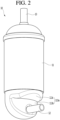
- FIG. 2 is a perspective view of an accumulator according to the first embodiment of the present invention
- FIG. 3 is a longitudinal sectional view of the accumulator of FIG. 2
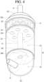
- FIG. 4 is a perspective view illustrating an inner portion of the accumulator of FIG. 2
- FIG. 5 is a perspective view of a liquid refrigerant inflow preventing plate coupled to a gas-liquid separation pipe according to the first embodiment of the present invention.
- an accumulator 10 is connected to the compressor 1 by a connecting piping 12.
- the accumulator 10 performs a function which separates the gaseous refrigerant in the refrigerant and supplies the separated gaseous refrigerant into the compression space of the cylinder 6.
- the liquid refrigerant separated through the accumulator 10 can be accommodated in the inner space of the accumulator 10.
- the refrigerant supplied to the compressor should be a low-temperature and low-pressure gaseous refrigerant.
- the low-temperature and low-pressure liquid refrigerant is partially mixed therein due to various factors. When such a liquid refrigerant flows directly into the compressor, since it may cause damage to the compressor, it is necessary to separate the liquid refrigerant from the accumulator.
- the accumulator 10 includes an accumulator main body 11 which forms an inner space, a connection pipe 12 which is coupled to one side (also referred to as second side) of the accumulator main body 11, and a suction pipe 13 which is coupled to the other side (also referred to as first side) of the accumulator main body 11.
- the first side may be a side opposite to the second side.
- the first side may be a top side of the accumulator 10.
- the second side may be a bottom side of the accumulator 10.
- the accumulator main body 11 includes a case.
- the term case may be used interchangeably with the term body herein.
- the case provides a space in which refrigerant flows in and is separated.
- the liquid refrigerant and the gaseous refrigerant can be accommodated in the case.
- the case may be formed as a generally cylindrical shape.
- the inner space formed by the case may be divided into an upper space S1 and a lower space S2 by a vibration preventing plate 114 to be described below and the lower space S2 may be divided into a first space S3 and a second space S4 by the liquid refrigerant inflow preventing plate 116 to be described below.
- the case includes a body 111 of which upper portion and lower portion are opened, an upper cap 112 which is coupled to the upper side of the body 111, and a lower cap 113 which is coupled to the lower side of the body 111.
- the body 111 is formed in a cylindrical shape and the upper portion and the lower portion thereof may be scaled by the upper cap 112 and the lower cap 113, respectively.
- the upper cap 112 and the lower cap 113 may be hemispherical or dome-shaped.
- the lower cap 113 may be formed in a container shape and may be coupled to the lower side of the body 111.
- the gaseous refrigerant and the oil can be accommodated in the inner space of the lower cap 113.
- a portion of the lower cap 113 may be recessed inward and the connection pipe 12 may be inserted into the recessed surface thereof.
- the lower cap 113 may include a recessed portion 113a which is partially recessed from the outside to the inside.
- the depressed portion 113a may include a stepped surface 113b.
- the stepped surface 113b may be formed to be spaced apart from an outer circumferential surface of the lower cap 113 by a predetermined distance in the center direction of the lower cap 113.
- the recessed portion 113a may further include an inclined surface 113c.
- the inclined surface 113c may be inclined upward from the upper end of the stepped surface 113b and extend in a direction away from the center of the lower cap 113.
- the inclined surface 113c may be smoothly connected to the stepped surface 113b.
- the working space which can connect the connection pipe 12 to the compressor 1 can be provided.
- the accumulator main body 11 may further include a screen member 115.
- the screen member 115 can be understood as a member for passing the gaseous refrigerant in the refrigerant sucked through the suction pipe 13 and for filtering the liquid refrigerant.
- the screen member 115 may be disposed on the upper portion of the body 111. Specifically, the screen member 115 is provided between the suction pipe 13 and the gas-liquid separation pipe 14 so that the foreign substances and the liquid refrigerant accommodated in the refrigerant passing through the suction pipe 13 can be filtered.
- the screen member 115 may be generally formed in a disc shape and may be fixed to the inner circumferential surface of the body 111.
- the screen member 115 may be formed with a refrigerant through hole 115a for discharging the filtered liquid refrigerant to the lower side.
- a plurality of the refrigerant through holes 115a may be formed and the plurality of refrigerant through holes 115a may be spaced apart from each other at a predetermined gap.
- the accumulator main body 11 further includes a gas-liquid separation pipe 14 for guiding the gaseous refrigerant in the case to the connection pipe 12.
- the gas-liquid separation pipe 14 extends by a predetermined length in the longitudinal direction of the case.
- the gas-liquid separation pipe 14 can be understood as a pipe through which the filtered gaseous refrigerant through the screen member 115 passes.
- the gas-liquid separation pipe 14 may be formed as a straight pipe portion which is disposed below the screen member 115 and is formed to be long in the vertical directior According to the invention, the gas-liquid separation pipe 14 is not connected to the connection pipe 12. Therefore, since the vibration generated in the compressor 1 is prevented from being directly transferred to the gas-liquid separation pipe 14 along the connection pipe 12, the noise due to the vibration of the connection pipe 12 can be reduced.
- the gas-liquid separation pipe 14 may be vertically positioned at the center of the body 111. In other words, the central axis of the gas-liquid separation pipe 14 may coincide with the center of the body 111. In addition, the central axis of the gas-liquid separation pipe 14 may coincide with the central axis of the suction pipe 13.
- the discharge end of the gas-liquid separation pipe 14 is positioned at a position spaced apart from the suction end of the connection pipe 12 by a predetermined distance upward.
- the accumulator main body 11 may further include a vibration preventing plate 114.
- the vibration preventing plate 114 may perform a function of supporting the gas-liquid separation pipe 14 positioned in the case.
- the vibration preventing plate 114 may be coupled to any point of an upper portion of the gas-liquid separation pipe 14 and may be fixed to the inner circumferential surface of the case. At this time, the vibration preventing plate 114 can divide the inner space of the case into the upper space S1 and the lower space S2.
- the vibration preventing plate 114 may be formed with an insertion hole for insertion into the gas-liquid separation pipe 14. Accordingly, the vibration preventing plate 114 can be fixed to the case while being inserted into the gas-liquid separation pipe 14.
- the vibration preventing plate 114 may be positioned below the screen member 115 and above the liquid refrigerant inflow preventing plate 116. Therefore, the liquid refrigerant filtered through the screen member 115 can fall downward and be collected on the upper surface of the vibration preventing plate 114.
- the vibration preventing plate 114 may be generally formed in a disc shape, and may be fixed to the inner circumferential surface of the body 111.
- the vibration preventing plate 114 may be formed with a refrigerant through hole 114a for discharging the liquid refrigerant collected in the upper surface of the vibration preventing plate 114 downward.
- a plurality of the refrigerant through holes 114a may be formed and the plurality of refrigerant through holes 114a may be spaced apart from each other at a predetermined gap.
- the accumulator main body 11 further includes a liquid refrigerant inflow preventing plate 116 for supporting the gas-liquid separation pipe 14.
- the liquid refrigerant inflow preventing plate 116 can be understood as a configuration for supporting the gas-liquid separation pipe 14 and collecting the liquid refrigerant dropped from the vibration preventing plate 114.
- the liquid refrigerant inflow preventing plate 116 is disposed below the vibration preventing plate 114 and divides the lower space S2 into a first space S3 on the upper side and a second space S4 on the lower side.
- the first space S3 can be understood as a space in which the liquid refrigerant filtered in the refrigerant is stored
- the second space S4 can be understood as a space in which the gaseous refrigerant passing through the gas-liquid separation pipe 14 and oil are accommodated.
- the liquid refrigerant inflow preventing plate 116 may be horizontally disposed in the case.
- the liquid refrigerant inflow preventing plate 116 may be positioned at a position spaced apart from the lower end of the case by a predetermined distance upward.
- the liquid refrigerant inflow preventing plate 116 includes a plate 116a having a through hole (not illustrated) formed therein.
- the liquid refrigerant inflow preventing plate 116 may further include at least one of an outer extension portion 116b which extends upward along the edge of the plate 116 and an inner extension portion 116c which extends upwardly along the periphery of the hole.
- the plate 116a may be formed in a circular shape and may be coupled with the gas-liquid separation pipe 14.
- the plate 116a can divide the lower space S2 into a first space S3 and a second space S4.
- the outer diameter of the plate 116 may be formed to be the same as the inner diameter of the lower cap 113.
- the outer circumferential surface of the plate 116 may be fixed to the inner circumferential surface of the lower cap 113.
- a fixing method pressing, welding, or the like can be applied, but the present invention is not limited thereto, and a fixing method using an adhesive such as a bond or a double-sided tape can be applied.
- the outer extension portion 116b can be understood as a component for fixing the plate 116a to the case.
- the outer extension portion 116b extends upward from the circumferential surface of the plate 116a, thereby performing a function of increasing the contact area for fixing between the plate 116a and the case.
- the outer extension portion 116b is described as being fixed to the lower cap 113 of the case, but it is not limited thereto.
- the outer extension portion 116b may be fixed to the inner circumferential surface of the body 111 rather than the lower cap 113 of the case.
- a through hole for inserting the gas-liquid separation pipe 14 may be formed at the center of the plate 116a. Accordingly, the plate 116a is fixed to the case in a state of being coupled to the gas-liquid separation pipe 14, thereby firmly supporting the gas-liquid separation pipe 14.
- an inner extension portion 116c extending upward from the plate 116 may be formed.
- the inner extension portion 116c may extend by a predetermined height from the plate 116 to stably hold the periphery of the gas-liquid separation pipe 14.
- the plate 116a may be provided with an oil recovery hole 116d for passing oil in the liquid refrigerant collected in the upper surface of the plate 116a.
- the oil recovery hole 116d can be understood as a hole for transferring the oil in the first space S3 to the second space S4.
- At least one oil recovery holes 116d may be formed in the plate 116a. Therefore, the oil present on the plate 116a can be dropped to the lower side of the plate 116a through the oil recovery hole 116d.
- the oil that is passed through the oil recovery hole 116d can be accommodated in the second space S4.
- the oil may move from the first space S3 to the second space S4, and in this process, at least a portion of the oil may be mixed with the gaseous refrigerant discharged from the gas-liquid separation pipe 14.
- the oil may be discharged to the connection pipe 12 together with the gaseous refrigerant.
- connection pipe 12 performs a function of a passage for providing the gaseous refrigerant or oil separated from the accumulator 10 to the compressor 1. For this, the connection pipe 12 connects one side of the accumulator 10 and one side of the compressor 1 to each other.
- connection pipe 12 can connect one side of the case and the suction side of the compressor. At this time, the connection pipe 12 may be inserted into the case through the side surface or the bottom surface of the case.
- connection pipe 12 may be formed as a straight pipe portion extending in the horizontal direction. At this time, the connection pipe 12 is not connected to the gas-liquid separation pipe 14. Accordingly, the vibration generated in the compressor 1 is prevented from being directly transferred to the gas-liquid separation pipe 14 along the connection pipe 12. Accordingly, the noise due to the vibration of the connection pipe 12 can be reduced.
- connection pipe 12 since the connection pipe 12 according to the present embodiment does not include a curved pipe, but is formed of only the straight pipe portion, there is an advantage that a bending process for forming the existing connection pipe is not required.
- connection pipe for connecting the compressor and the accumulator is formed of a curved pipe. Therefore, a process of bending the connection pipe is further required.
- a connection pipe is made of a workable material, for example, a copper (Cu) material, in order to bend the connection pipe.
- the copper material is more expensive than the steel material, the manufacturing cost is increased.
- connection pipe according to the present invention is formed only by the straight pipe portion and thus the process of bending the connection pipe is not required, the connection pipe can be made of a steel material of low price and thus there is an advantage that the manufacturing cost thereof is decreased.
- connection pipe 12 may pass through a case of the accumulator 10, for example, a side surface or a bottom surface of the lower cap 113. Accordingly, a portion of the connection pipe 12 may be positioned in the lower cap 113.
- the suction pipe 13 can be understood as a pipe through which a low-temperature and low-pressure refrigerant flows from a heat exchanger (for example, evaporator) not illustrated.
- the refrigerant flowing through the suction pipe 13 may be a mixed refrigerant in which the gaseous refrigerant and the liquid refrigerant are mixed.
- the suction pipe 13 may extend from one side of the heat exchanger (not illustrated) and may be connected to the upper cap 112.
- a low-temperature and low-pressure refrigerant is sucked through the suction pipe 13 from the heat exchanger (for example, evaporator) not illustrated.
- the refrigerant sucked through the suction pipe 13 passes through the screen member 115 and foreign matter and liquid refrigerant are filtered therefrom.
- the gaseous refrigerant in the refrigerant passes through the screen member 115 and then is moved to the second space S4 formed by the lower cap 113 through the gas-liquid separation pipe 14.
- the liquid refrigerant filtered by the screen member 115 drops down through the refrigerant through hole 115a formed in the screen member 115 and is collected in the vibration preventing plate 114.
- the liquid refrigerant collected in the vibration preventing plate 114 drops through the liquid refrigerant through hole 114a formed in the vibration preventing plate 114 and is collected in the liquid refrigerant inflow preventing plate 116.
- the liquid refrigerant dropped into the upper surface of the liquid refrigerant inflow preventing plate 116 is lifted while being vaporized by the surrounding heat and is moved to the second space S4 through the gas-liquid separation pipe 14.
- the gaseous refrigerant flowing into the second space S4 is sucked into the suction portion of the cylinder 6 through the connection pipe 12.
- the oil dropped into the second space S4 through the oil recovery hole 116d is mixed with the gaseous refrigerant flowing through the second space S4 and is discharged along with the gaseous refrigerant through the connection pipe 12.
- FIG. 6 is a longitudinal sectional view of an accumulator according to a second embodiment of the present invention.
- the present embodiment is the same as the first embodiment in other portions and is characterized in that there is a difference only in the shape of the case. Accordingly, only characteristic portions of the present embodiment will be described below and the same portions as those of the first embodiment will be referred to those.
- the accumulator 10 includes an accumulator main body 11 which forms an inner space, a suction pipe 13 which is coupled to one side of the accumulator main body 11, and a connection pipe 12 which connects the other side of the accumulator main body 11 and the suction side of the compressor 1.
- the accumulator main body 11 includes a case 111a which forms a space in which liquid refrigerant and gaseous refrigerant are accommodated.
- the case 111a may be formed in a cylindrical shape.
- the case 111a may be integrally formed and may have an erected cylindrical shape.
- connection pipe 12 may be inserted into a side surface of the case 111a.
- connection pipe 12 may be inserted into the case 111a through the side surface of the case 111a.
- connection pipe 12 may be formed horizontally.
- the suction end of the connection pipe 12 may be positioned below the discharge end of the gas-liquid separation pipe 14 positioned in the case 111a.
- FIG. 7 is a longitudinal sectional view of an accumulator according to a third embodiment of the present invention.
- the present embodiment is the same as the second embodiment in the other portions and is characterized in that there is a difference only in the shape of the connection pipe. Accordingly, only characteristic portions of the present embodiment will be described below and the same portions as those of the second embodiment will be referred to those.
- the accumulator 10 includes an accumulator main body 11 which forms an inner space, a suction pipe 13 which is coupled to one side of the accumulator main body 11, and a connection pipe 12 which connects the other side of the accumulator main body 11 and the suction side of the compressor 1.
- the accumulator main body 11 includes a case 111a which forms a space in which liquid refrigerant and gaseous refrigerant are accommodated.
- the case 111a may be formed in a cylindrical shape.
- the case 111a may be integrally formed and may have an erected cylindrical shape.
- connection pipe 12 may be inserted into a side surface of the case 111a.
- connection pipe 12 may be inserted into the case 111a through the side surface of the case 111a.
- connection pipe 12 includes a horizontally extending horizontal portion 12a and a bent portion 12b which is bent at an end portion of the horizontal portion 12a.
- the bending portion 12b may be referred to as suction end of the suction pipe 12, too.
- the horizontal portion 12a may extend horizontally and pass through a side surface of the case 111a and then be positioned in the case 111a.
- the bent portion 12b may be bent at the end portion of the horizontal portion 12a positioned in the case 111a.
- the bent portion 12b may extend upward from an end portion of the horizontal portion 12a. At this time, the bent portion 12b may be disposed to face the gas-liquid separation pipe 14. In addition, the vertical central axis of the bent portion 12b may coincide with the vertical central axis of the gas-liquid separation pipe 14.
- FIG. 8 is a longitudinal sectional view of an accumulator according to a fourth embodiment of the present invention.
- the present embodiment is the same as the second embodiment in other portions and is characterized in that there is a difference only in the shape of the case. Accordingly, only characteristic portions of the present embodiment will be described below and the same portions as those of the second embodiment will be referred to those.
- the accumulator 10 includes an accumulator main body 11 which forms an inner space, a suction pipe 13 which is coupled to one side of the accumulator main body 11, and a connection pipe 12 which connects the other side of the accumulator main body 11 and the suction side of the compressor 1.
- the accumulator main body 11 includes a case 111a which forms a space in which liquid refrigerant and gaseous refrigerant are accommodated.
- the case 111a may be formed in a cylindrical shape.
- the case 111a may be integrally formed and may have an erected cylindrical shape.
- connection pipe 12 may be inserted into the bottom surface of the case 111a.
- connection pipe 12 may be inserted into the case 111a through the bottom surface of the case 111a.
- connection pipe 12 includes a horizontally extending horizontal portion 12a and a bent portion 12b which is bent at an end portion of the horizontal portion 12a.
- the horizontal portion 12a horizontally extends from the lower side of the case 111a.
- the bent portion 12b may be bent at the end portion of the horizontal portion 12a and pass through the bottom surface of the case 111a.
- connection pipe 12 is horizontally extended from the lower side of the case 111a and then the end portion thereof is bent upwardly and inserted through the bottom surface of the case 111a.
- the bent portion 12b of the connection pipe 12 may be disposed to face the gas-liquid separation pipe 14.
- the vertical central axis of the bent portion 12b may coincide with the vertical central axis of the gas-liquid separation pipe 14.
- connection pipe connecting the compressor and the accumulator and the gas-liquid separation pipe are separated from each other, it is possible to minimize transfer of the vibration generated from the compressor to the accumulator through the connection pipe. Accordingly, since the vibration of the accumulator by the vibration generated in the compressor is minimized, noise due to the vibration can be greatly reduced.
- connection pipe connecting the compressor and the accumulator and the gas-liquid separation pipe can be formed as straight pipe portions, the process of machining the connection pipe into the bending pipe can be omitted.
- process of bending the connection pipe and the gas-liquid separation pipe can be omitted, it is possible to widely select a range of materials to be applied to the pipe, and accordingly, there is an advantage of decreasing manufacturing prices by adopting pipe made of low-cost material.
Landscapes
- Engineering & Computer Science (AREA)
- Physics & Mathematics (AREA)
- Mechanical Engineering (AREA)
- Thermal Sciences (AREA)
- General Engineering & Computer Science (AREA)
- Chemical & Material Sciences (AREA)
- Analytical Chemistry (AREA)
- Power Engineering (AREA)
- Compressor (AREA)
- Applications Or Details Of Rotary Compressors (AREA)
Claims (12)
- Druckspeicher (10), der mit einem Kompressor (1) verbunden werden kann, wobei der Druckspeicher Folgendes umfasst:ein Gehäuse (1a, 111a), das konfiguriert ist, ein flüssiges Kühlmittel und ein gasförmiges Kühlmittel aufzunehmen;ein Saugrohr (13), das auf einer ersten Seite des Gehäuses (1a, 111a) bereitgestellt ist;ein Verbindungsrohr (12), das konfiguriert ist, eine zweite Seite des Gehäuses (1a, 111a) mit einer Saugseite des Kompressors (1) zu verbinden;ein Rohr (14) zum Trennen von Gas und Flüssigkeit, das im Gehäuse (1a, 111a) bereitgestellt ist und konfiguriert ist, das gasförmige Kühlmittel zum Verbindungsrohr (12) zu leiten,ein Austrittsende des Rohrs (14) zum Trennen von Gas und Flüssigkeit, das von einem Saugende (12b) des Verbindungsrohrs (12) mit einem zuvor festgelegten Abstand in einer Richtung nach oben beabstandet ist; undeine Platte (116) zum Verhindern des Einströmens von flüssigem Kühlmittel, die im Gehäuse (1a, 111a) bereitgestellt ist, die das Austrittsende des Rohrs (14) zum Trennen von Gas und Flüssigkeit trägt;wobei das Rohr (14) zum Trennen von Gas und Flüssigkeit vom Verbindungsrohr (12) getrennt ist, undwobei die Platte (116) zum Verhindern des Einströmens von flüssigem Kühlmittel einen inneren Hohlraum (S2) des Gehäuses (1a, 111a) in einen ersten Hohlraum (S3) und einen zweiten Hohlraum (S4) trennt, wobei sich der erste Hohlraum (S3) über dem zweiten Hohlraum (S4) befindet.
- Druckspeicher (10) nach Anspruch 1, wobei sich das Rohr (14) zum Trennen von Gas und Flüssigkeit um eine zuvor festgelegte Länge in der Längsrichtung des Gehäuses (1a, 111a) erstreckt.
- Druckspeicher (10) nach einem der Ansprüche 1 oder 2, wobei die Mittelachse des Rohrs (14) zum Trennen von Gas und Flüssigkeit und die Mittelachse des Gehäuses (1a, 111a) überlappen.
- Druckspeicher (10) nach einem der Ansprüche 1 bis 3, wobei die Mittelachse des Saugrohrs (13) und die Mittelachse des Rohrs (14) zum Trennen von Gas und Flüssigkeit überlappen.
- Druckspeicher (10) nach Anspruch 1,wobei die Platte (116) zum Verhindern des Einströmens von flüssigem Kühlmittel im Gehäuse (1a, 111a) horizontal angeordnet ist, undwobei sich das Rohr (14) zum Trennen von Gas und Flüssigkeit von der Platte (116) zum Verhindern des Einströmens von flüssigem Kühlmittel nach oben erstreckt.
- Druckspeicher (10) nach einem der Ansprüche 1 oder 5, wobei ein Ölrückgewinnungsloch (116d) auf einer Seite der Platte (116) zum Verhindern des Einströmens von flüssigem Kühlmittel ausgebildet ist.
- Druckspeicher (10) nach einem der Ansprüche 1, 5 oder 6, wobei die Platte (116) zum Verhindern des Einströmens von flüssigem Kühlmittel von einem unteren Endabschnitt des Gehäuses (1a, 111a) mit einem zuvor festgelegten Abstand in einer Richtung nach oben beabstandet ist.
- Druckspeicher (10) nach einem der Ansprüche 1 oder 5 bis 7, wobei die Platte (116) zum Verhindern des Einströmens von flüssigem Kühlmittel eine Platte (116a) umfasst, die ein Durchgangsloch hat, durch das das Rohr (14) zum Trennen von Gas und Flüssigkeit verläuft.
- Druckspeicher (10) nach Anspruch 8, wobei die Platte (116a) ein Ölrückgewinnungsloch (116d) umfasst, durch das Öl im ersten Hohlraum (S3) im zweiten Hohlraum (S4) aufgenommen werden kann.
- Druckspeicher (10) nach einem der Ansprüche 1 oder 5 bis 9, wobei die Platte (116) zum Verhindern des Einströmens von flüssigem Kühlmittel ferner einen inneren Erweiterungsabschnitt (116c) umfasst, der sich von einer Außenkante des Durchgangslochs nach oben erstreckt und einen Abschnitt des Rohrs (14) zum Trennen von Gas und Flüssigkeit umgibt.
- Druckspeicher (10) nach einem der Ansprüche 8 bis 10, wobei die Platte (116) zum Verhindern des Einströmens von flüssigem Kühlmittel ferner einen äußeren Erweiterungsabschnitt (116b) umfasst, der sich von einer Außenkante der Platte (116a) nach oben erstreckt, und
wobei eine Außenumfangsfläche des äußeren Erweiterungsabschnitts (116b) an einer Innenumfangsfläche des Gehäuses (1a, 111a) befestigt ist. - Druckspeicher (10) nach einem der Ansprüche 1 oder 5 bis 11, wobei das Gehäuse (1a, 111a) Folgendes umfasst:einen zylindrischen Körper (111, 111a);eine obere Kappe (112), die einen oberen Endabschnitt des Körpers (111, 111a) bedeckt; undeine untere Kappe (113), die einen unteren Endabschnitt des Körpers (111, 111a) bedeckt, undwobei die Platte (116) zum Verhindern des Einströmens von flüssigem Kühlmittel an einer Innenumfangsfläche des Körpers (111, 111a) oder an einer Innenumfangsfläche der unteren Kappe (113) befestigt ist, wobei die Platte (116) zum Verhindern des Einströmens von flüssigem Kühlmittel so angeordnet ist, dass sie einen inneren Hohlraum des Körpers (111, 111a) und einen inneren Hohlraum der unteren Kappe (113) trennt.
Applications Claiming Priority (1)
| Application Number | Priority Date | Filing Date | Title |
|---|---|---|---|
| KR1020170051668A KR20180118397A (ko) | 2017-04-21 | 2017-04-21 | 어큐뮬레이터 |
Publications (2)
| Publication Number | Publication Date |
|---|---|
| EP3392579A1 EP3392579A1 (de) | 2018-10-24 |
| EP3392579B1 true EP3392579B1 (de) | 2024-08-21 |
Family
ID=59914301
Family Applications (1)
| Application Number | Title | Priority Date | Filing Date |
|---|---|---|---|
| EP17191281.9A Active EP3392579B1 (de) | 2017-04-21 | 2017-09-15 | Akkumulator |
Country Status (4)
| Country | Link |
|---|---|
| US (1) | US10502469B2 (de) |
| EP (1) | EP3392579B1 (de) |
| KR (1) | KR20180118397A (de) |
| CN (1) | CN108731316A (de) |
Families Citing this family (5)
| Publication number | Priority date | Publication date | Assignee | Title |
|---|---|---|---|---|
| CN108426392A (zh) * | 2018-05-05 | 2018-08-21 | 珠海格力电器股份有限公司 | 冷媒提纯装置 |
| CN111219317B (zh) * | 2020-03-25 | 2025-08-19 | 珠海凌达压缩机有限公司 | 一种分液器和压缩机 |
| CN115031451A (zh) * | 2022-06-06 | 2022-09-09 | 中国第一汽车股份有限公司 | 一种汽车空调用储液干燥器 |
| KR20250014103A (ko) | 2023-07-19 | 2025-02-03 | 엘지전자 주식회사 | 열공급장치 |
| JP2026001798A (ja) * | 2024-06-20 | 2026-01-08 | 日本キヤリア株式会社 | アキュムレーター、圧縮機、および冷凍サイクル装置 |
Citations (1)
| Publication number | Priority date | Publication date | Assignee | Title |
|---|---|---|---|---|
| EP2896914B1 (de) * | 2012-09-07 | 2021-04-21 | Denso Corporation | Akkumulator |
Family Cites Families (21)
| Publication number | Priority date | Publication date | Assignee | Title |
|---|---|---|---|---|
| US4009596A (en) * | 1975-07-21 | 1977-03-01 | Tecumseh Products Company | Suction accumulator |
| US4182136A (en) * | 1977-12-22 | 1980-01-08 | Tecumseh Products Company | Suction accumulator |
| US4187695A (en) * | 1978-11-07 | 1980-02-12 | Virginia Chemicals Inc. | Air-conditioning system having recirculating and flow-control means |
| US4209997A (en) * | 1978-11-13 | 1980-07-01 | Fryman Richard K | Accumulator cycling switch |
| JPH02128060U (de) * | 1989-03-28 | 1990-10-22 | ||
| US5233840A (en) * | 1992-08-19 | 1993-08-10 | Mainstream Engineering Corporation | Method and apparatus for cooling refrigerant recovery system tanks and the like |
| JPH1114199A (ja) * | 1997-06-24 | 1999-01-22 | Mitsubishi Electric Corp | アキュムレータ |
| US6708519B1 (en) * | 2002-12-30 | 2004-03-23 | Bristol Compressors, Inc. | Accumulator with internal desiccant |
| CN1715662A (zh) * | 2004-06-28 | 2006-01-04 | 乐金电子(天津)电器有限公司 | 压缩机用气液分离器的泡沫清除装置 |
| CN1880767A (zh) * | 2005-06-13 | 2006-12-20 | 乐金电子(天津)电器有限公司 | 压缩机用低噪音储液罐 |
| CN101995123A (zh) * | 2009-08-24 | 2011-03-30 | 乐金电子(天津)电器有限公司 | 密闭型压缩机的储液器结构 |
| JP5366856B2 (ja) | 2010-02-17 | 2013-12-11 | 三菱電機株式会社 | ベーンロータリ型流体装置及び圧縮機 |
| JP2012145307A (ja) * | 2011-01-14 | 2012-08-02 | Mitsubishi Electric Corp | 密閉型圧縮機 |
| CN203272134U (zh) * | 2013-04-11 | 2013-11-06 | 珠海格力电器股份有限公司 | 新型旋转式压缩机 |
| JP2015105792A (ja) * | 2013-11-29 | 2015-06-08 | ダイキン工業株式会社 | 室外機 |
| CN203615661U (zh) * | 2013-12-03 | 2014-05-28 | 广东美芝精密制造有限公司 | 储液器和具有其的压缩机 |
| CN103940160B (zh) * | 2014-03-14 | 2016-08-31 | 安徽美芝精密制造有限公司 | 储液器 |
| CN204388254U (zh) * | 2014-12-18 | 2015-06-10 | 广东美的制冷设备有限公司 | 压缩机组件、空调室外机及空调 |
| CN105042958A (zh) * | 2015-08-25 | 2015-11-11 | 无锡华琳制冷机械有限公司 | 一种新型压缩机储液器 |
| CN105042960A (zh) * | 2015-08-25 | 2015-11-11 | 无锡华琳制冷机械有限公司 | 一种压缩机储液器 |
| CN205503459U (zh) * | 2016-04-07 | 2016-08-24 | 天津九齐冷冻科技有限公司 | 一种压缩机 |
-
2017
- 2017-04-21 KR KR1020170051668A patent/KR20180118397A/ko not_active Ceased
- 2017-07-28 CN CN201710628184.XA patent/CN108731316A/zh active Pending
- 2017-09-15 EP EP17191281.9A patent/EP3392579B1/de active Active
- 2017-09-19 US US15/709,211 patent/US10502469B2/en active Active
Patent Citations (1)
| Publication number | Priority date | Publication date | Assignee | Title |
|---|---|---|---|---|
| EP2896914B1 (de) * | 2012-09-07 | 2021-04-21 | Denso Corporation | Akkumulator |
Also Published As
| Publication number | Publication date |
|---|---|
| US20180306475A1 (en) | 2018-10-25 |
| CN108731316A (zh) | 2018-11-02 |
| KR20180118397A (ko) | 2018-10-31 |
| EP3392579A1 (de) | 2018-10-24 |
| US10502469B2 (en) | 2019-12-10 |
Similar Documents
| Publication | Publication Date | Title |
|---|---|---|
| US10502469B2 (en) | Accumulator | |
| CN102725526B (zh) | 压缩机和冷冻装置 | |
| US8419394B2 (en) | Hermetic compressor including a backflow preventing portion and refrigeration cycle device having the same | |
| US20080170955A1 (en) | Scroll compressor with crankshaft venting | |
| EP2218914A2 (de) | Spiralfluidmaschine | |
| EP3636923B1 (de) | Spiralverdichter und kühlkreislaufvorrichtung | |
| US11215387B2 (en) | Accumulator | |
| CN102003390B (zh) | 涡旋压缩机 | |
| EP2317146B1 (de) | Ölrückgewinnungselement sowie motormechanismus und verdichter damit | |
| CN110234880A (zh) | 涡旋式压缩机 | |
| EP3575605B1 (de) | Hermetischer verdichter | |
| EP3034964A1 (de) | Verdichtereinheit, verdichter und kühlmittelkreislauf | |
| JPH04232394A (ja) | 密閉形スクロール圧縮機 | |
| JP6998531B2 (ja) | スクロール圧縮機 | |
| EP3919745B1 (de) | Verdichter und kühlkreisvorrichtung damit | |
| WO2018139309A1 (ja) | スクロール圧縮機 | |
| EP1764507A2 (de) | Verdichter | |
| JP6331786B2 (ja) | 圧縮機 | |
| KR101474019B1 (ko) | 전동기구 및 이를 적용한 압축기 | |
| KR20180090324A (ko) | 로터리 압축기 | |
| EP3760868B1 (de) | Kompressor | |
| KR101990137B1 (ko) | 어큐물레이터 및 이를 포함하는 압축 유닛 | |
| EP4513033A1 (de) | Verwendung als kältemittel für verdichter, verdichter und kältekreislaufvorrichtung | |
| US20220128280A1 (en) | Compressor, and refrigeration device | |
| KR101328816B1 (ko) | 로터리식 2단 압축기 |
Legal Events
| Date | Code | Title | Description |
|---|---|---|---|
| PUAI | Public reference made under article 153(3) epc to a published international application that has entered the european phase |
Free format text: ORIGINAL CODE: 0009012 |
|
| STAA | Information on the status of an ep patent application or granted ep patent |
Free format text: STATUS: REQUEST FOR EXAMINATION WAS MADE |
|
| 17P | Request for examination filed |
Effective date: 20170915 |
|
| AK | Designated contracting states |
Kind code of ref document: A1 Designated state(s): AL AT BE BG CH CY CZ DE DK EE ES FI FR GB GR HR HU IE IS IT LI LT LU LV MC MK MT NL NO PL PT RO RS SE SI SK SM TR |
|
| AX | Request for extension of the european patent |
Extension state: BA ME |
|
| STAA | Information on the status of an ep patent application or granted ep patent |
Free format text: STATUS: EXAMINATION IS IN PROGRESS |
|
| 17Q | First examination report despatched |
Effective date: 20211008 |
|
| GRAP | Despatch of communication of intention to grant a patent |
Free format text: ORIGINAL CODE: EPIDOSNIGR1 |
|
| STAA | Information on the status of an ep patent application or granted ep patent |
Free format text: STATUS: GRANT OF PATENT IS INTENDED |
|
| INTG | Intention to grant announced |
Effective date: 20240325 |
|
| GRAS | Grant fee paid |
Free format text: ORIGINAL CODE: EPIDOSNIGR3 |
|
| GRAA | (expected) grant |
Free format text: ORIGINAL CODE: 0009210 |
|
| STAA | Information on the status of an ep patent application or granted ep patent |
Free format text: STATUS: THE PATENT HAS BEEN GRANTED |
|
| AK | Designated contracting states |
Kind code of ref document: B1 Designated state(s): AL AT BE BG CH CY CZ DE DK EE ES FI FR GB GR HR HU IE IS IT LI LT LU LV MC MK MT NL NO PL PT RO RS SE SI SK SM TR |
|
| REG | Reference to a national code |
Ref country code: GB Ref legal event code: FG4D |
|
| REG | Reference to a national code |
Ref country code: CH Ref legal event code: EP |
|
| REG | Reference to a national code |
Ref country code: DE Ref legal event code: R096 Ref document number: 602017084212 Country of ref document: DE |
|
| REG | Reference to a national code |
Ref country code: IE Ref legal event code: FG4D |
|
| REG | Reference to a national code |
Ref country code: LT Ref legal event code: MG9D |
|
| REG | Reference to a national code |
Ref country code: NL Ref legal event code: MP Effective date: 20240821 |
|
| PG25 | Lapsed in a contracting state [announced via postgrant information from national office to epo] |
Ref country code: NO Free format text: LAPSE BECAUSE OF FAILURE TO SUBMIT A TRANSLATION OF THE DESCRIPTION OR TO PAY THE FEE WITHIN THE PRESCRIBED TIME-LIMIT Effective date: 20241121 |
|
| REG | Reference to a national code |
Ref country code: AT Ref legal event code: MK05 Ref document number: 1715843 Country of ref document: AT Kind code of ref document: T Effective date: 20240821 |
|
| PG25 | Lapsed in a contracting state [announced via postgrant information from national office to epo] |
Ref country code: NL Free format text: LAPSE BECAUSE OF FAILURE TO SUBMIT A TRANSLATION OF THE DESCRIPTION OR TO PAY THE FEE WITHIN THE PRESCRIBED TIME-LIMIT Effective date: 20240821 Ref country code: FI Free format text: LAPSE BECAUSE OF FAILURE TO SUBMIT A TRANSLATION OF THE DESCRIPTION OR TO PAY THE FEE WITHIN THE PRESCRIBED TIME-LIMIT Effective date: 20240821 Ref country code: PL Free format text: LAPSE BECAUSE OF FAILURE TO SUBMIT A TRANSLATION OF THE DESCRIPTION OR TO PAY THE FEE WITHIN THE PRESCRIBED TIME-LIMIT Effective date: 20240821 Ref country code: PT Free format text: LAPSE BECAUSE OF FAILURE TO SUBMIT A TRANSLATION OF THE DESCRIPTION OR TO PAY THE FEE WITHIN THE PRESCRIBED TIME-LIMIT Effective date: 20241223 Ref country code: GR Free format text: LAPSE BECAUSE OF FAILURE TO SUBMIT A TRANSLATION OF THE DESCRIPTION OR TO PAY THE FEE WITHIN THE PRESCRIBED TIME-LIMIT Effective date: 20241122 |
|
| PG25 | Lapsed in a contracting state [announced via postgrant information from national office to epo] |
Ref country code: BG Free format text: LAPSE BECAUSE OF FAILURE TO SUBMIT A TRANSLATION OF THE DESCRIPTION OR TO PAY THE FEE WITHIN THE PRESCRIBED TIME-LIMIT Effective date: 20240821 |
|
| PG25 | Lapsed in a contracting state [announced via postgrant information from national office to epo] |
Ref country code: LV Free format text: LAPSE BECAUSE OF FAILURE TO SUBMIT A TRANSLATION OF THE DESCRIPTION OR TO PAY THE FEE WITHIN THE PRESCRIBED TIME-LIMIT Effective date: 20240821 |
|
| PG25 | Lapsed in a contracting state [announced via postgrant information from national office to epo] |
Ref country code: IS Free format text: LAPSE BECAUSE OF FAILURE TO SUBMIT A TRANSLATION OF THE DESCRIPTION OR TO PAY THE FEE WITHIN THE PRESCRIBED TIME-LIMIT Effective date: 20241221 Ref country code: AT Free format text: LAPSE BECAUSE OF FAILURE TO SUBMIT A TRANSLATION OF THE DESCRIPTION OR TO PAY THE FEE WITHIN THE PRESCRIBED TIME-LIMIT Effective date: 20240821 |
|
| PG25 | Lapsed in a contracting state [announced via postgrant information from national office to epo] |
Ref country code: HR Free format text: LAPSE BECAUSE OF FAILURE TO SUBMIT A TRANSLATION OF THE DESCRIPTION OR TO PAY THE FEE WITHIN THE PRESCRIBED TIME-LIMIT Effective date: 20240821 |
|
| PG25 | Lapsed in a contracting state [announced via postgrant information from national office to epo] |
Ref country code: ES Free format text: LAPSE BECAUSE OF FAILURE TO SUBMIT A TRANSLATION OF THE DESCRIPTION OR TO PAY THE FEE WITHIN THE PRESCRIBED TIME-LIMIT Effective date: 20240821 Ref country code: RS Free format text: LAPSE BECAUSE OF FAILURE TO SUBMIT A TRANSLATION OF THE DESCRIPTION OR TO PAY THE FEE WITHIN THE PRESCRIBED TIME-LIMIT Effective date: 20241121 |
|
| PG25 | Lapsed in a contracting state [announced via postgrant information from national office to epo] |
Ref country code: RS Free format text: LAPSE BECAUSE OF FAILURE TO SUBMIT A TRANSLATION OF THE DESCRIPTION OR TO PAY THE FEE WITHIN THE PRESCRIBED TIME-LIMIT Effective date: 20241121 Ref country code: PT Free format text: LAPSE BECAUSE OF FAILURE TO SUBMIT A TRANSLATION OF THE DESCRIPTION OR TO PAY THE FEE WITHIN THE PRESCRIBED TIME-LIMIT Effective date: 20241223 Ref country code: PL Free format text: LAPSE BECAUSE OF FAILURE TO SUBMIT A TRANSLATION OF THE DESCRIPTION OR TO PAY THE FEE WITHIN THE PRESCRIBED TIME-LIMIT Effective date: 20240821 Ref country code: NO Free format text: LAPSE BECAUSE OF FAILURE TO SUBMIT A TRANSLATION OF THE DESCRIPTION OR TO PAY THE FEE WITHIN THE PRESCRIBED TIME-LIMIT Effective date: 20241121 Ref country code: NL Free format text: LAPSE BECAUSE OF FAILURE TO SUBMIT A TRANSLATION OF THE DESCRIPTION OR TO PAY THE FEE WITHIN THE PRESCRIBED TIME-LIMIT Effective date: 20240821 Ref country code: LV Free format text: LAPSE BECAUSE OF FAILURE TO SUBMIT A TRANSLATION OF THE DESCRIPTION OR TO PAY THE FEE WITHIN THE PRESCRIBED TIME-LIMIT Effective date: 20240821 Ref country code: IS Free format text: LAPSE BECAUSE OF FAILURE TO SUBMIT A TRANSLATION OF THE DESCRIPTION OR TO PAY THE FEE WITHIN THE PRESCRIBED TIME-LIMIT Effective date: 20241221 Ref country code: HR Free format text: LAPSE BECAUSE OF FAILURE TO SUBMIT A TRANSLATION OF THE DESCRIPTION OR TO PAY THE FEE WITHIN THE PRESCRIBED TIME-LIMIT Effective date: 20240821 Ref country code: GR Free format text: LAPSE BECAUSE OF FAILURE TO SUBMIT A TRANSLATION OF THE DESCRIPTION OR TO PAY THE FEE WITHIN THE PRESCRIBED TIME-LIMIT Effective date: 20241122 Ref country code: FI Free format text: LAPSE BECAUSE OF FAILURE TO SUBMIT A TRANSLATION OF THE DESCRIPTION OR TO PAY THE FEE WITHIN THE PRESCRIBED TIME-LIMIT Effective date: 20240821 Ref country code: ES Free format text: LAPSE BECAUSE OF FAILURE TO SUBMIT A TRANSLATION OF THE DESCRIPTION OR TO PAY THE FEE WITHIN THE PRESCRIBED TIME-LIMIT Effective date: 20240821 Ref country code: BG Free format text: LAPSE BECAUSE OF FAILURE TO SUBMIT A TRANSLATION OF THE DESCRIPTION OR TO PAY THE FEE WITHIN THE PRESCRIBED TIME-LIMIT Effective date: 20240821 Ref country code: AT Free format text: LAPSE BECAUSE OF FAILURE TO SUBMIT A TRANSLATION OF THE DESCRIPTION OR TO PAY THE FEE WITHIN THE PRESCRIBED TIME-LIMIT Effective date: 20240821 |
|
| PG25 | Lapsed in a contracting state [announced via postgrant information from national office to epo] |
Ref country code: DK Free format text: LAPSE BECAUSE OF FAILURE TO SUBMIT A TRANSLATION OF THE DESCRIPTION OR TO PAY THE FEE WITHIN THE PRESCRIBED TIME-LIMIT Effective date: 20240821 Ref country code: SM Free format text: LAPSE BECAUSE OF FAILURE TO SUBMIT A TRANSLATION OF THE DESCRIPTION OR TO PAY THE FEE WITHIN THE PRESCRIBED TIME-LIMIT Effective date: 20240821 Ref country code: RO Free format text: LAPSE BECAUSE OF FAILURE TO SUBMIT A TRANSLATION OF THE DESCRIPTION OR TO PAY THE FEE WITHIN THE PRESCRIBED TIME-LIMIT Effective date: 20240821 |
|
| PG25 | Lapsed in a contracting state [announced via postgrant information from national office to epo] |
Ref country code: EE Free format text: LAPSE BECAUSE OF FAILURE TO SUBMIT A TRANSLATION OF THE DESCRIPTION OR TO PAY THE FEE WITHIN THE PRESCRIBED TIME-LIMIT Effective date: 20240821 |
|
| PG25 | Lapsed in a contracting state [announced via postgrant information from national office to epo] |
Ref country code: CZ Free format text: LAPSE BECAUSE OF FAILURE TO SUBMIT A TRANSLATION OF THE DESCRIPTION OR TO PAY THE FEE WITHIN THE PRESCRIBED TIME-LIMIT Effective date: 20240821 |
|
| PG25 | Lapsed in a contracting state [announced via postgrant information from national office to epo] |
Ref country code: SK Free format text: LAPSE BECAUSE OF FAILURE TO SUBMIT A TRANSLATION OF THE DESCRIPTION OR TO PAY THE FEE WITHIN THE PRESCRIBED TIME-LIMIT Effective date: 20240821 |
|
| REG | Reference to a national code |
Ref country code: CH Ref legal event code: PL |
|
| PG25 | Lapsed in a contracting state [announced via postgrant information from national office to epo] |
Ref country code: LU Free format text: LAPSE BECAUSE OF NON-PAYMENT OF DUE FEES Effective date: 20240915 |
|
| REG | Reference to a national code |
Ref country code: DE Ref legal event code: R097 Ref document number: 602017084212 Country of ref document: DE |
|
| PLBE | No opposition filed within time limit |
Free format text: ORIGINAL CODE: 0009261 |
|
| STAA | Information on the status of an ep patent application or granted ep patent |
Free format text: STATUS: NO OPPOSITION FILED WITHIN TIME LIMIT |
|
| PG25 | Lapsed in a contracting state [announced via postgrant information from national office to epo] |
Ref country code: MC Free format text: LAPSE BECAUSE OF FAILURE TO SUBMIT A TRANSLATION OF THE DESCRIPTION OR TO PAY THE FEE WITHIN THE PRESCRIBED TIME-LIMIT Effective date: 20240821 |
|
| REG | Reference to a national code |
Ref country code: BE Ref legal event code: MM Effective date: 20240930 |
|
| PG25 | Lapsed in a contracting state [announced via postgrant information from national office to epo] |
Ref country code: BE Free format text: LAPSE BECAUSE OF NON-PAYMENT OF DUE FEES Effective date: 20240930 |
|
| PG25 | Lapsed in a contracting state [announced via postgrant information from national office to epo] |
Ref country code: FR Free format text: LAPSE BECAUSE OF NON-PAYMENT OF DUE FEES Effective date: 20241021 |
|
| GBPC | Gb: european patent ceased through non-payment of renewal fee |
Effective date: 20241121 |
|
| PG25 | Lapsed in a contracting state [announced via postgrant information from national office to epo] |
Ref country code: CH Free format text: LAPSE BECAUSE OF NON-PAYMENT OF DUE FEES Effective date: 20240930 |
|
| PG25 | Lapsed in a contracting state [announced via postgrant information from national office to epo] |
Ref country code: IE Free format text: LAPSE BECAUSE OF NON-PAYMENT OF DUE FEES Effective date: 20240915 |
|
| 26N | No opposition filed |
Effective date: 20250522 |
|
| PG25 | Lapsed in a contracting state [announced via postgrant information from national office to epo] |
Ref country code: SE Free format text: LAPSE BECAUSE OF FAILURE TO SUBMIT A TRANSLATION OF THE DESCRIPTION OR TO PAY THE FEE WITHIN THE PRESCRIBED TIME-LIMIT Effective date: 20240821 |
|
| PGFP | Annual fee paid to national office [announced via postgrant information from national office to epo] |
Ref country code: DE Payment date: 20250805 Year of fee payment: 9 |
|
| PGFP | Annual fee paid to national office [announced via postgrant information from national office to epo] |
Ref country code: IT Payment date: 20250806 Year of fee payment: 9 |
|
| PG25 | Lapsed in a contracting state [announced via postgrant information from national office to epo] |
Ref country code: GB Free format text: LAPSE BECAUSE OF NON-PAYMENT OF DUE FEES Effective date: 20241121 |
|
| PG25 | Lapsed in a contracting state [announced via postgrant information from national office to epo] |
Ref country code: CY Free format text: LAPSE BECAUSE OF FAILURE TO SUBMIT A TRANSLATION OF THE DESCRIPTION OR TO PAY THE FEE WITHIN THE PRESCRIBED TIME-LIMIT; INVALID AB INITIO Effective date: 20170915 |
|
| PG25 | Lapsed in a contracting state [announced via postgrant information from national office to epo] |
Ref country code: HU Free format text: LAPSE BECAUSE OF FAILURE TO SUBMIT A TRANSLATION OF THE DESCRIPTION OR TO PAY THE FEE WITHIN THE PRESCRIBED TIME-LIMIT; INVALID AB INITIO Effective date: 20170915 |