EP3392500A1 - Machine synchrone à réluctance à deux enroulements composée d'un enroulement d'excitation et d'un enroulement de puissance séparé - Google Patents
Machine synchrone à réluctance à deux enroulements composée d'un enroulement d'excitation et d'un enroulement de puissance séparé Download PDFInfo
- Publication number
- EP3392500A1 EP3392500A1 EP17425042.3A EP17425042A EP3392500A1 EP 3392500 A1 EP3392500 A1 EP 3392500A1 EP 17425042 A EP17425042 A EP 17425042A EP 3392500 A1 EP3392500 A1 EP 3392500A1
- Authority
- EP
- European Patent Office
- Prior art keywords
- winding
- power
- rotating field
- excitation
- field machine
- Prior art date
- Legal status (The legal status is an assumption and is not a legal conclusion. Google has not performed a legal analysis and makes no representation as to the accuracy of the status listed.)
- Granted
Links
- 238000004804 winding Methods 0.000 title claims abstract description 153
- 230000005284 excitation Effects 0.000 title claims abstract description 70
- 230000001360 synchronised effect Effects 0.000 title description 7
- 238000000034 method Methods 0.000 claims description 38
- 230000008878 coupling Effects 0.000 claims description 9
- 238000010168 coupling process Methods 0.000 claims description 9
- 238000005859 coupling reaction Methods 0.000 claims description 9
- 238000010586 diagram Methods 0.000 description 12
- 230000008901 benefit Effects 0.000 description 5
- 238000004891 communication Methods 0.000 description 4
- 238000012986 modification Methods 0.000 description 3
- 230000004048 modification Effects 0.000 description 3
- 238000013461 design Methods 0.000 description 2
- 230000006870 function Effects 0.000 description 2
- 230000006698 induction Effects 0.000 description 2
- 238000012545 processing Methods 0.000 description 2
- 238000001816 cooling Methods 0.000 description 1
- 230000003247 decreasing effect Effects 0.000 description 1
- 230000000694 effects Effects 0.000 description 1
- 230000004907 flux Effects 0.000 description 1
- 230000009467 reduction Effects 0.000 description 1
- 230000009466 transformation Effects 0.000 description 1
Images


Classifications
-
- H—ELECTRICITY
- H02—GENERATION; CONVERSION OR DISTRIBUTION OF ELECTRIC POWER
- H02K—DYNAMO-ELECTRIC MACHINES
- H02K21/00—Synchronous motors having permanent magnets; Synchronous generators having permanent magnets
- H02K21/02—Details
- H02K21/04—Windings on magnets for additional excitation ; Windings and magnets for additional excitation
- H02K21/046—Windings on magnets for additional excitation ; Windings and magnets for additional excitation with rotating permanent magnets and stationary field winding
-
- F—MECHANICAL ENGINEERING; LIGHTING; HEATING; WEAPONS; BLASTING
- F02—COMBUSTION ENGINES; HOT-GAS OR COMBUSTION-PRODUCT ENGINE PLANTS
- F02N—STARTING OF COMBUSTION ENGINES; STARTING AIDS FOR SUCH ENGINES, NOT OTHERWISE PROVIDED FOR
- F02N11/00—Starting of engines by means of electric motors
- F02N11/04—Starting of engines by means of electric motors the motors being associated with current generators
-
- H—ELECTRICITY
- H02—GENERATION; CONVERSION OR DISTRIBUTION OF ELECTRIC POWER
- H02K—DYNAMO-ELECTRIC MACHINES
- H02K11/00—Structural association of dynamo-electric machines with electric components or with devices for shielding, monitoring or protection
- H02K11/04—Structural association of dynamo-electric machines with electric components or with devices for shielding, monitoring or protection for rectification
- H02K11/042—Rectifiers associated with rotating parts, e.g. rotor cores or rotary shafts
-
- H—ELECTRICITY
- H02—GENERATION; CONVERSION OR DISTRIBUTION OF ELECTRIC POWER
- H02K—DYNAMO-ELECTRIC MACHINES
- H02K19/00—Synchronous motors or generators
- H02K19/02—Synchronous motors
- H02K19/10—Synchronous motors for multi-phase current
- H02K19/12—Synchronous motors for multi-phase current characterised by the arrangement of exciting windings, e.g. for self-excitation, compounding or pole-changing
-
- H—ELECTRICITY
- H02—GENERATION; CONVERSION OR DISTRIBUTION OF ELECTRIC POWER
- H02K—DYNAMO-ELECTRIC MACHINES
- H02K19/00—Synchronous motors or generators
- H02K19/16—Synchronous generators
- H02K19/26—Synchronous generators characterised by the arrangement of exciting windings
-
- H—ELECTRICITY
- H02—GENERATION; CONVERSION OR DISTRIBUTION OF ELECTRIC POWER
- H02K—DYNAMO-ELECTRIC MACHINES
- H02K3/00—Details of windings
- H02K3/04—Windings characterised by the conductor shape, form or construction, e.g. with bar conductors
- H02K3/28—Layout of windings or of connections between windings
-
- H—ELECTRICITY
- H02—GENERATION; CONVERSION OR DISTRIBUTION OF ELECTRIC POWER
- H02M—APPARATUS FOR CONVERSION BETWEEN AC AND AC, BETWEEN AC AND DC, OR BETWEEN DC AND DC, AND FOR USE WITH MAINS OR SIMILAR POWER SUPPLY SYSTEMS; CONVERSION OF DC OR AC INPUT POWER INTO SURGE OUTPUT POWER; CONTROL OR REGULATION THEREOF
- H02M7/00—Conversion of ac power input into dc power output; Conversion of dc power input into ac power output
-
- H—ELECTRICITY
- H02—GENERATION; CONVERSION OR DISTRIBUTION OF ELECTRIC POWER
- H02P—CONTROL OR REGULATION OF ELECTRIC MOTORS, ELECTRIC GENERATORS OR DYNAMO-ELECTRIC CONVERTERS; CONTROLLING TRANSFORMERS, REACTORS OR CHOKE COILS
- H02P21/00—Arrangements or methods for the control of electric machines by vector control, e.g. by control of field orientation
-
- H—ELECTRICITY
- H02—GENERATION; CONVERSION OR DISTRIBUTION OF ELECTRIC POWER
- H02P—CONTROL OR REGULATION OF ELECTRIC MOTORS, ELECTRIC GENERATORS OR DYNAMO-ELECTRIC CONVERTERS; CONTROLLING TRANSFORMERS, REACTORS OR CHOKE COILS
- H02P27/00—Arrangements or methods for the control of AC motors characterised by the kind of supply voltage
- H02P27/04—Arrangements or methods for the control of AC motors characterised by the kind of supply voltage using variable-frequency supply voltage, e.g. inverter or converter supply voltage
- H02P27/06—Arrangements or methods for the control of AC motors characterised by the kind of supply voltage using variable-frequency supply voltage, e.g. inverter or converter supply voltage using dc to ac converters or inverters
-
- H—ELECTRICITY
- H02—GENERATION; CONVERSION OR DISTRIBUTION OF ELECTRIC POWER
- H02P—CONTROL OR REGULATION OF ELECTRIC MOTORS, ELECTRIC GENERATORS OR DYNAMO-ELECTRIC CONVERTERS; CONTROLLING TRANSFORMERS, REACTORS OR CHOKE COILS
- H02P9/00—Arrangements for controlling electric generators for the purpose of obtaining a desired output
- H02P9/14—Arrangements for controlling electric generators for the purpose of obtaining a desired output by variation of field
- H02P9/36—Arrangements for controlling electric generators for the purpose of obtaining a desired output by variation of field using armature-reaction-excited machines
-
- F—MECHANICAL ENGINEERING; LIGHTING; HEATING; WEAPONS; BLASTING
- F02—COMBUSTION ENGINES; HOT-GAS OR COMBUSTION-PRODUCT ENGINE PLANTS
- F02N—STARTING OF COMBUSTION ENGINES; STARTING AIDS FOR SUCH ENGINES, NOT OTHERWISE PROVIDED FOR
- F02N11/00—Starting of engines by means of electric motors
- F02N11/08—Circuits or control means specially adapted for starting of engines
- F02N2011/0881—Components of the circuit not provided for by previous groups
- F02N2011/0885—Capacitors, e.g. for additional power supply
-
- F—MECHANICAL ENGINEERING; LIGHTING; HEATING; WEAPONS; BLASTING
- F02—COMBUSTION ENGINES; HOT-GAS OR COMBUSTION-PRODUCT ENGINE PLANTS
- F02N—STARTING OF COMBUSTION ENGINES; STARTING AIDS FOR SUCH ENGINES, NOT OTHERWISE PROVIDED FOR
- F02N11/00—Starting of engines by means of electric motors
- F02N11/08—Circuits or control means specially adapted for starting of engines
- F02N2011/0881—Components of the circuit not provided for by previous groups
- F02N2011/0896—Inverters for electric machines, e.g. starter-generators
-
- H—ELECTRICITY
- H02—GENERATION; CONVERSION OR DISTRIBUTION OF ELECTRIC POWER
- H02K—DYNAMO-ELECTRIC MACHINES
- H02K19/00—Synchronous motors or generators
- H02K19/02—Synchronous motors
- H02K19/10—Synchronous motors for multi-phase current
- H02K19/103—Motors having windings on the stator and a variable reluctance soft-iron rotor without windings
-
- H—ELECTRICITY
- H02—GENERATION; CONVERSION OR DISTRIBUTION OF ELECTRIC POWER
- H02K—DYNAMO-ELECTRIC MACHINES
- H02K19/00—Synchronous motors or generators
- H02K19/16—Synchronous generators
- H02K19/18—Synchronous generators having windings each turn of which co-operates only with poles of one polarity, e.g. homopolar generators
- H02K19/20—Synchronous generators having windings each turn of which co-operates only with poles of one polarity, e.g. homopolar generators with variable-reluctance soft-iron rotors without winding
-
- H—ELECTRICITY
- H02—GENERATION; CONVERSION OR DISTRIBUTION OF ELECTRIC POWER
- H02K—DYNAMO-ELECTRIC MACHINES
- H02K19/00—Synchronous motors or generators
- H02K19/16—Synchronous generators
- H02K19/22—Synchronous generators having windings each turn of which co-operates alternately with poles of opposite polarity, e.g. heteropolar generators
- H02K19/24—Synchronous generators having windings each turn of which co-operates alternately with poles of opposite polarity, e.g. heteropolar generators with variable-reluctance soft-iron rotors without winding
-
- H—ELECTRICITY
- H02—GENERATION; CONVERSION OR DISTRIBUTION OF ELECTRIC POWER
- H02P—CONTROL OR REGULATION OF ELECTRIC MOTORS, ELECTRIC GENERATORS OR DYNAMO-ELECTRIC CONVERTERS; CONTROLLING TRANSFORMERS, REACTORS OR CHOKE COILS
- H02P2101/00—Special adaptation of control arrangements for generators
- H02P2101/45—Special adaptation of control arrangements for generators for motor vehicles, e.g. car alternators
Definitions
- the present subject matter relates generally to rotating field machines.
- Rotating electric machines are used for a wide variety of applications, such as automotive applications, aerospace applications, marine applications, industrial applications, and numerous other applications.
- a rotating electric machine can be an electrical motor.
- the rotor configured to rotate with respect to the stator to convert electrical energy to mechanical energy.
- Rotating electrical machines also include electric generators. The relative rotation between the rotor and the stator can convert mechanical energy to electrical energy.
- an electric generator is an electric generator that is used onboard an aircraft.
- the variable frequency starter-generator VFSG
- rotating field machines and other machines e.g., synchronous reluctance machines, induction machines, etc.
- the power converter has to manage all the power flowing from the machine to an electrical system leading to a machine with decreased overall reliability and an increased cost, volume and weight.
- the rotating field machine includes a stator and a rotor.
- the rotor being mounted for rotation with respect to the stator.
- the stator includes a first winding.
- the first winding can be an excitation winding configured to receive an excitation current.
- the stator further includes a second winding.
- the second winding can be a power winding configured to accommodate power flow through the rotating field machine.
- the excitation winding and the power winding are located in the stator such that the excitation winding and power winding are in electrical quadrature with respect to one another. In some embodiments, the excitation winding is 90° out of electrical phase with respect to the power winding. In some embodiments, the excitation winding is associated with d-axis current and the power winding is associated with q-axis current for the rotating field machine.
- the rotating field machine is coupled to a control system, the control system configured to operate the rotating field machine in a starting mode and in a generating mode.
- both the excitation winding and the power winding are coupled to one or more power converters.
- the power winding is coupled to a DC bus via a bridge rectifier.
- the power winding is coupled to a variable frequency constant voltage bus.
- a control device is configured to control the power converter to manage excitation current flowing in the excitation winding to control a generated power in the power winding.
- the rotating field machine is a synchronous reluctance machine.
- the rotating field machine includes a stator and a rotor.
- the rotor can be mounted for rotation with respect to the stator.
- the stator includes an excitation winding configured to receive an excitation current.
- the stator further includes a power winding configured to accommodate power flow in the rotating field machine.
- the control system can be configured to perform operations.
- the operations can include determining to operate the rotating field machine in a starting mode. During the starting mode, the operations can include energizing the excitation winding and the power winding with a power converter.
- the operations further include operating the power converter to start the rotating field machine.
- the operations further include determining to operate the rotating field machine in a generating mode. During the generating mode, the operations include decoupling the power winding from the power converter.
- the operations further include operating the power converter to manage excitation current flowing in the excitation winding to control a generated power in the power winding.
- the operations comprise coupling the power winding to a DC bus via a rectifier. In some embodiments, during the generating mode, the operations comprise coupling the power winding to an AC bus.
- the excitation winding and the power winding are located in the stator such that the excitation winding and the power winding are in electrical quadrature with respect to one another. In some embodiments, the excitation winding is positioned 90° out of electrical phase with respect to the power winding.
- the rotating field machine includes a stator and a rotor.
- the rotor can be mounted for rotation with respect to the stator.
- the stator includes an excitation winding configured to receive an excitation current.
- the stator further includes a power winding configured to accommodate power flow through the rotating field machine.
- the method further includes determining to operate the rotating field machine in a starting mode. During the starting mode, the method includes energizing the excitation winding and the power winding with a power converter.
- the method further includes operating the power converter to start the rotating field machine.
- the method further includes determining to operate the rotating field machine in a generating mode. During the generating mode, the method includes decoupling the power winding from the power converter.
- the method further includes operating the power converter to manage excitation current flowing in the excitation winding to control a generated power in the power winding.
- the excitation winding and the power winding are located in the stator such that the excitation winding and power winding are in electrical quadrature with respect to one another. In some embodiments, the excitation winding is positioned 90° out of electrical phase with the power winding. In some embodiments, during the generating mode, the method comprises coupling the power winding to a DC bus via a rectifier. In some embodiments, during the generating mode, the method comprises coupling the power winding to an AC bus.
- Example aspects of the present disclosure are directed to a dual-winding rotating field machine.
- the variable frequency starter-generator VFSG
- the VFSG can be a commonly used machine for the motor/generator.
- the VFSG can have a complex design including electromagnetic components with many rotating elements as well as cooling components for the many sources of heat.
- some applications require the machines to be coupled to a switching power converter.
- the converter has to manage all the power that is flowing from the machine to the electrical system during a starting mode. This can reduce the reliability of the machine and can increase the weight, volume and cost of the machine.
- a dual-winding rotating field machine such as a modified synchronous reluctance machine
- the machine can have a stator that has two separate windings (dual-winding machine).
- the first winding can be used to control an excitation current and the second winding can be used to control a main power flow.
- the switching power converter can be responsible for managing the excitation winding only.
- the machine can be operated in a starting mode or a generating mode.
- both windings can be coupled to one or more power converters.
- the power winding can be coupled to a DC bus with a diode bridge in between.
- the diode bridge rectifier can be obtained from the same converter legs used for hard switching (free wheel diodes) or integrated in the power converter.
- the power winding can be coupled to a variable frequency constant voltage (or AC) bus without any power electronics in between. As a result, the power converter can be used to manage the excitation power only.
- example aspects of the present disclosure can provide a number of technical effects and benefits.
- a stator with two separate windings can allow the power converter to deal with a reduced proportion of the total power.
- FIG. 1 depicts a block diagram of an example dual-winding rotating field machine 200 according to example embodiments of the present disclosure.
- Machine 200 can be a synchronous reluctance machine or any other type of rotating field machine (e.g., permanent magnet assisted synchronous reluctance machine), an induction machine, an interior permanent magnet machine, surface mounted permanent magnet machine.
- the machine 200 can include a rotor 150 and a stator 140.
- the rotor 150 can be mounted for rotation with respect to the stator 140.
- the stator 140 can include a first winding and a second winding.
- the first winding can be an excitation winding 220.
- the second winding can be a power winding 230.
- the power winding 230 can be coupled to a main rectifier 160 to rectify the power. Power generated by the machine 200 can be applied to many different applications including, but not limited to, automotive and aeronautical applications.
- Machine 200 can include a switching power converter 170.
- Power converter 170 can be used to convert DC power to AC power.
- power converter 170 can be configured for operation using a pulse width modulation (PWM) arrangement of insulated gate bipolar transistors (IGBTs) switching devices or other switching devices.
- a control device 210 can be configured to control operation of the converter by providing one or more gating commands to the switching devices.
- the control device 210 can be configured to control operations of machine 200 according to example embodiments of the present disclosure.
- FIG. 4 discussed below, shows one example of a flow diagram that can be implemented using control device 210. There can be multiple converters 170 depending on needs and design.
- FIG. 2 depicts a circuit diagram of an example dual-winding rotating field machine 200 when operating in a generating mode.
- the excitation winding 220 can be coupled to the power converter 170.
- the power winding 230 can be coupled to a DC bus with a diode bridge rectifier 160 in between.
- Excitation winding 220 and power winding 230 can be located in the stator 140 such that the excitation winding 220 and the power winding 230 are in electrical quadrature. In this way, the excitation winding 220 can be associated with d-axis components and the power winding 230 can be associated with q-axis components.
- D-axis and q-axis have been here defined following the well-known theory of Clarke and Park transformation, the d-axis being aligned with the main rotor flux.
- the excitation winding 220 can be positioned 90° out of electrical phase with respect to the power winding 230.
- the power converter 170 can be responsible for managing the excitation power only.
- power converter 170 can be designed to have a reduced size, weight and volume.
- FIG. 3 depicts a plot diagram 300 representation of the d-axis current versus the q-axis current of a synchronous reluctance machine according to example embodiments of the present disclosure.
- the d-axis current is represented by I d and the q-axis current is represented by I q .
- the stator 140 of dual-winding reluctance machine 200 can be designed with two separate windings to physically separate the d-axis current and the q-axis current.
- the power converter 170 can be used to control the excitation power only.
- the power converter 170 only has to manage the d-axis current (and d-axis power). As a result, the power converter 170 can be designed such that it is sized to handle the d-axis power only.
- the d-axis voltage can be less than the q-axis voltage thus leading to an advantage (on apparent power V*I) that is even more than the simple d-axis v. q-axis current ratio.
- the power converter 170 can be designed to have a reduced size, weight, and volume while increasing reliability.
- the present disclosure can be advantageous in managing power in aeronautical applications where the power needs of an aircraft can be up to several kilowatts (kW) or several hundred kilowatts (kW) of power.
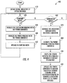
- FIG. 4 depicts a flow diagram of an example method 400 according to example embodiments of the present disclosure.
- FIG. 4 depicts steps performed in a particular order for purposes of illustration and discussion. Those of ordinary skill in the art, using the disclosure provided herein, will understand that the method discussed herein can be adapted, rearranged, expanded, omitted, performed simultaneously, or modified in various ways without deviating from the scope of the present disclosure.
- Method 400 can be performed by control device 210 or by separate devices.
- the method can include obtaining, from control device 210, a signal indicative of an operating mode.
- the operating mode can be either a starting mode or a generating mode.
- the method can include determining whether the operating mode is a starting mode. If the operating mode is not the starting mode, the method can proceed to (460) to determine whether the operating mode is a generating mode. If the operating mode is determined to be the starting mode, the method can include energizing an excitation winding 220 at (430).
- the method can include energizing a power winding 230 with a switching power converter 170.
- Power winding 230 can be configured to accommodate power flow through the rotating field machine 200.
- the method can include operating the power converter 170 to start the rotating field machine 200. After starting the rotating field machine 200, the method can loop back to (410) to obtain a signal indicative of the operating mode. The method can perform step (420) again to determine if the signal is indicative of the starting mode and proceed to (460) after determining that the signal is not indicative of the starting mode.
- the method can include determining whether the signal obtained is indicative of a generating mode. If the signal obtained is for the generating mode, the method can proceed to operate the machine 200 in the generating mode.
- the method can include energizing the excitation winding 220 with the power converter 170.
- the excitation winding 220 can correspond to d-axis current and d-axis power.
- the method can include decoupling the power winding 230 from the power converter 170.
- the power winding 230 can be associated with q-axis current and q-axis power. As discussed above in FIG. 3 , the q-axis current (and q-axis power) can be greater than the d-axis current (and d-axis power). As a result, decoupling the power winding 230 from the power converter 170 can allow the power converter 170 to deal with a reduced amount of the total power.
- the method can include coupling the power winding 230 to a variable frequency constant voltage bus.
- the power winding 230 can be coupled to a DC bus via a diode bridge rectifier 160.
- the generated power can be controlled by the excitation winding 220 only.
- the method can include operating the power converter 170 to manage excitation current flowing in the excitation winding 220 to control a generated power in the power winding 230.
- the d-axis current (and the d-axis power) can be lower than the q-axis current (and q-axis power).
- the d-axis voltage can be lower than q-axis voltage which can lead to more advantages on apparent power V*I.
- FIG. 5 depicts an example control device 210 (e.g., one or more controllers) according to example aspects of the present disclosure. As shown in FIG. 1 , the control device 210 can be coupled to power converter 170.
- control device 210 e.g., one or more controllers
- the control device 210 can be used, for example, as a control device 210 for power converter 170.
- the control device 210 can include one or more processor(s) 212 and one or more memory device(s) 214.
- the one or more processor(s) 212 can include any suitable processing device, such as a microprocessor, microcontrol device, integrated circuit, logic device, and/or other suitable processing device.
- the one or more memory device(s) 214 can include one or more computer-readable media, including, but not limited to, non-transitory computer-readable media, RAM, ROM, hard drives, flash drives, and/or other memory devices.
- the one or more memory device(s) 214 can store information accessible by the one or more processor(s) 212, including computer-readable instructions that can be executed by the one or more processor(s) 212.
- the instructions can be any set of instructions that when executed by the one or more processor(s) 212, cause the one or more processor(s) 212 to perform operations.
- the instructions can be executed by the one or more processor(s) 212 to cause the one or more processor(s) to perform operations, such as any of the operations and functions for which the control device 210 is configured.
- the operations can be used for controlling power converter 170 (e.g., control method 400), as described herein, and/or any other operations or functions of the one or more control device 210.
- the instructions can be software written in any suitable programming language or can be implemented in hardware. Additionally, and/or alternatively, the instructions can be executed in logically and/or virtually separate threads on processor(s) 212.
- the memory device(s) 214 can further store data that can be accessed by the processor(s) 212.
- the data can include data indicative of power flows, current flows, temperatures, actual voltages, nominal voltages, gating commands, switching patterns, and/or any other data and/or information described herein.
- the control device 210 can also include a communication interface 216 used to communicate, for example, with the other components of machine 200 (e.g., via a network).
- the communication interface 216 can include any suitable components for interfacing with one or more network(s), including for example, transmitters, receivers, ports, control devices, antennas, and/or other suitable components.
- the communication interface 216 can be configured to communicate with one or more sensors or voltage sensors or temperature sensors.
- the communication interface 216 can be configured to communicate with a control device, such as a control device 210.
Landscapes
- Engineering & Computer Science (AREA)
- Power Engineering (AREA)
- Chemical & Material Sciences (AREA)
- Combustion & Propulsion (AREA)
- Mechanical Engineering (AREA)
- General Engineering & Computer Science (AREA)
- Control Of Eletrric Generators (AREA)
- Synchronous Machinery (AREA)
Priority Applications (4)
| Application Number | Priority Date | Filing Date | Title |
|---|---|---|---|
| EP17425042.3A EP3392500B1 (fr) | 2017-04-18 | 2017-04-18 | Machine synchrone à réluctance à deux enroulements composée d'un enroulement d'excitation et d'un enroulement de puissance séparé |
| PCT/US2018/032690 WO2018195559A2 (fr) | 2017-04-18 | 2018-05-15 | Machine à réluctance synchrone à double enroulement composée d'un enroulement d'excitation et d'un enroulement de puissance séparé |
| US16/606,006 US11894737B2 (en) | 2017-04-18 | 2018-05-15 | Dual-winding synchronous reluctance machine composed of an excitation winding and a separate power winding |
| CN201880025690.2A CN110731043B (zh) | 2017-04-18 | 2018-05-15 | 励磁绕组和独立电力绕组组成的双绕组同步磁阻机 |
Applications Claiming Priority (1)
| Application Number | Priority Date | Filing Date | Title |
|---|---|---|---|
| EP17425042.3A EP3392500B1 (fr) | 2017-04-18 | 2017-04-18 | Machine synchrone à réluctance à deux enroulements composée d'un enroulement d'excitation et d'un enroulement de puissance séparé |
Publications (2)
| Publication Number | Publication Date |
|---|---|
| EP3392500A1 true EP3392500A1 (fr) | 2018-10-24 |
| EP3392500B1 EP3392500B1 (fr) | 2022-07-27 |
Family
ID=59296804
Family Applications (1)
| Application Number | Title | Priority Date | Filing Date |
|---|---|---|---|
| EP17425042.3A Active EP3392500B1 (fr) | 2017-04-18 | 2017-04-18 | Machine synchrone à réluctance à deux enroulements composée d'un enroulement d'excitation et d'un enroulement de puissance séparé |
Country Status (4)
| Country | Link |
|---|---|
| US (1) | US11894737B2 (fr) |
| EP (1) | EP3392500B1 (fr) |
| CN (1) | CN110731043B (fr) |
| WO (1) | WO2018195559A2 (fr) |
Families Citing this family (2)
| Publication number | Priority date | Publication date | Assignee | Title |
|---|---|---|---|---|
| CN112366991A (zh) * | 2020-11-30 | 2021-02-12 | 华中科技大学 | 一种同步磁阻式起动发电系统 |
| US11711036B1 (en) | 2022-05-06 | 2023-07-25 | Hamilton Sundstrand Corporation | Electric power generation system (EPGS) controller excitation system architecture for variable frequency generators |
Citations (3)
| Publication number | Priority date | Publication date | Assignee | Title |
|---|---|---|---|---|
| US4772802A (en) * | 1987-08-19 | 1988-09-20 | Sundstrand Corporation | Starting/generating system |
| US20030034755A1 (en) * | 2001-08-13 | 2003-02-20 | Krefta Ronald John | Method and system for controlling a synchronous machine using a changeable cycle-conduction angle |
| EP1716630A1 (fr) * | 2004-02-20 | 2006-11-02 | Honeywell International, Inc. | Procede et appareil de detection de position pour systeme de generateur a moteur synchrone |
Family Cites Families (24)
| Publication number | Priority date | Publication date | Assignee | Title |
|---|---|---|---|---|
| GB232968A (en) | 1924-04-23 | 1926-07-08 | British Thomson Houston Co Ltd | Improvements in and relating to alternating current dynamo electric machines |
| US4093869A (en) * | 1976-04-13 | 1978-06-06 | Westinghouse Electric Corp. | Quadrature axis field brushless exciter |
| US4743777A (en) | 1986-03-07 | 1988-05-10 | Westinghouse Electric Corp. | Starter generator system with two stator exciter windings |
| US5083077A (en) | 1990-07-31 | 1992-01-21 | The State Of Oregon Acting By And Through The State Board Of Higher Education On Behalf Of Oregon State University | Brushless doubly-fed generation system for vehicles |
| US5493201A (en) | 1994-11-15 | 1996-02-20 | Sundstrand Corporation | Starter/generator system and method utilizing a low voltage source |
| US5811905A (en) | 1997-01-07 | 1998-09-22 | Emerson Electric Co. | Doubly-fed switched reluctance machine |
| JPH10225098A (ja) | 1997-02-09 | 1998-08-21 | Fumihide Haba | 発電機および電動機 |
| WO2000014695A1 (fr) | 1998-09-03 | 2000-03-16 | Aspen Motion Technologies, Inc. | Systeme resolveur redondant a faible cout |
| JP3917390B2 (ja) | 2001-07-06 | 2007-05-23 | 株式会社日立製作所 | 発電電動装置 |
| US20050162030A1 (en) | 2004-01-27 | 2005-07-28 | Shah Manoj R. | Brushless exciter with electromagnetically decoupled dual excitation systems for starter-generator applications |
| US7227271B2 (en) | 2004-09-21 | 2007-06-05 | Honeywell International Inc. | Method and apparatus for controlling an engine start system |
| US7301310B2 (en) * | 2005-08-24 | 2007-11-27 | Honeywell International, Inc. | Excitation controlled synchronous permanent magnet machine |
| JP4887890B2 (ja) | 2006-04-25 | 2012-02-29 | 株式会社デンソー | 車両用モータ装置 |
| NZ556760A (en) * | 2007-07-26 | 2008-12-24 | Auckland Uniservices Ltd | An electric generator |
| US8097968B2 (en) | 2007-12-21 | 2012-01-17 | Honeywell International, Inc. | Position-controlled start from the AC line using a synchronous machine |
| KR20100021214A (ko) * | 2008-08-14 | 2010-02-24 | 한국델파이주식회사 | 차량용 스타터-알터네이터 일체형 모터 제어장치 |
| US8593030B2 (en) | 2010-07-09 | 2013-11-26 | Nikhil Mondal | Rotating electric machine for generating a constant frequency AC Power Supply from a variable speed primemover |
| US8310115B2 (en) | 2010-07-23 | 2012-11-13 | General Electric Company | High power-density, high efficiency, non-permanent magnet electric machine |
| US9041232B2 (en) | 2013-10-11 | 2015-05-26 | General Electric Company | Electric generator system |
| US9209741B2 (en) | 2014-02-24 | 2015-12-08 | The Boeing Company | Method and system for controlling synchronous machine as generator/starter |
| CN103986293B (zh) | 2014-05-09 | 2017-04-12 | 苏州市双马机电有限公司 | 一种单三相通用的小型凸极式自励恒压同步发电机 |
| JP2018509124A (ja) * | 2015-02-18 | 2018-03-29 | ジーイー・アビエイション・システムズ・エルエルシー | 航空機用始動および発電システム |
| JP6226901B2 (ja) * | 2015-03-09 | 2017-11-08 | 三菱電機株式会社 | 発電システム |
| US9667232B2 (en) | 2015-05-13 | 2017-05-30 | Raytheon Company | System and method for parallel configuration of hybrid energy storage module |
-
2017
- 2017-04-18 EP EP17425042.3A patent/EP3392500B1/fr active Active
-
2018
- 2018-05-15 US US16/606,006 patent/US11894737B2/en active Active
- 2018-05-15 CN CN201880025690.2A patent/CN110731043B/zh active Active
- 2018-05-15 WO PCT/US2018/032690 patent/WO2018195559A2/fr active Application Filing
Patent Citations (3)
| Publication number | Priority date | Publication date | Assignee | Title |
|---|---|---|---|---|
| US4772802A (en) * | 1987-08-19 | 1988-09-20 | Sundstrand Corporation | Starting/generating system |
| US20030034755A1 (en) * | 2001-08-13 | 2003-02-20 | Krefta Ronald John | Method and system for controlling a synchronous machine using a changeable cycle-conduction angle |
| EP1716630A1 (fr) * | 2004-02-20 | 2006-11-02 | Honeywell International, Inc. | Procede et appareil de detection de position pour systeme de generateur a moteur synchrone |
Non-Patent Citations (1)
| Title |
|---|
| BOJAN STUMBERGER ET AL: "Design of synchronous reluctance generator with dual stator windings and anisotropic rotor with flux barriers", PRZEGLAD ELEKTROTECHNICZNY, vol. R.88, no. 12b/2012, 1 December 2012 (2012-12-01), PO, pages 16 - 19, XP055397677, ISSN: 0033-2097 * |
Also Published As
| Publication number | Publication date |
|---|---|
| EP3392500B1 (fr) | 2022-07-27 |
| US20210211028A1 (en) | 2021-07-08 |
| CN110731043A (zh) | 2020-01-24 |
| WO2018195559A2 (fr) | 2018-10-25 |
| CN110731043B (zh) | 2022-08-30 |
| WO2018195559A3 (fr) | 2019-02-28 |
| US11894737B2 (en) | 2024-02-06 |
Similar Documents
| Publication | Publication Date | Title |
|---|---|---|
| US10608565B2 (en) | Systems and methods for rotating a crankshaft to start an engine | |
| Reed et al. | Offline identification of induction machine parameters with core loss estimation using the stator current locus | |
| He et al. | Stator temperature estimation of direct-torque-controlled induction machines via active flux or torque injection | |
| US10833605B2 (en) | Space vector modulation in aerospace applications | |
| EP3006257A1 (fr) | Procédé de commande pour un appareil chargeur destiné à un véhicule électrique | |
| Duran et al. | A simple braking method for six-phase induction motor drives with unidirectional power flow in the base-speed region | |
| US11894737B2 (en) | Dual-winding synchronous reluctance machine composed of an excitation winding and a separate power winding | |
| CN107070335A (zh) | 双pwm永磁电力驱动系统转矩前馈控制方法及其控制装置 | |
| EP2889178B1 (fr) | Commande de générateur synchrone sur la base d'optimiseur de flux | |
| Nguyen et al. | Energy optimal control of an electrically excited synchronous motor used as traction drive | |
| US9537350B2 (en) | Switch-mode power supply with a dual primary transformer | |
| JP6949165B2 (ja) | 交流回転機の制御装置 | |
| Prabhu et al. | Critical review on torque ripple sources and mitigation control strategies of BLDC motors in electric vehicle applications | |
| Taniguchi et al. | Noise reduction method by injected frequency control for position sensorless control of permanent magnet synchronous motor | |
| EP3723270B1 (fr) | Actionneur pour avion, procédé de commande d'actionneur pour avion et système d'actionneur pour avion | |
| JP6113651B2 (ja) | 多相電動機駆動装置 | |
| CN106655949A (zh) | 永磁同步电机的控制系统、控制方法及无人飞行器 | |
| CN106487307A (zh) | 永磁同步电机的防退磁控制系统、方法及无人飞行器 | |
| JP2020174514A (ja) | 航空機用アクチュエータ、航空機用アクチュエータの駆動方法、航空機用アクチュエータシステム | |
| Shreiner et al. | Electromechanical resources of a frequency-controlled synchronous electric drive in continuous periodic operating modes | |
| Suzuki et al. | Maximum Torque Minimum Peak Phase Current of a Dual Winding Interior Permanent Magnet Synchronous Motor | |
| Hmidet et al. | A new direct speed estimation and control of the induction machine benchmark: design and experimental validation | |
| US11146183B2 (en) | Method for controlling an inverter | |
| Schuster et al. | A comparison of two methods for sensorless position estimation using the electromagnetic force at an electrically excited synchronous machine | |
| JP6991282B1 (ja) | 回転機の制御装置 |
Legal Events
| Date | Code | Title | Description |
|---|---|---|---|
| PUAI | Public reference made under article 153(3) epc to a published international application that has entered the european phase |
Free format text: ORIGINAL CODE: 0009012 |
|
| STAA | Information on the status of an ep patent application or granted ep patent |
Free format text: STATUS: THE APPLICATION HAS BEEN PUBLISHED |
|
| AK | Designated contracting states |
Kind code of ref document: A1 Designated state(s): AL AT BE BG CH CY CZ DE DK EE ES FI FR GB GR HR HU IE IS IT LI LT LU LV MC MK MT NL NO PL PT RO RS SE SI SK SM TR |
|
| AX | Request for extension of the european patent |
Extension state: BA ME |
|
| STAA | Information on the status of an ep patent application or granted ep patent |
Free format text: STATUS: REQUEST FOR EXAMINATION WAS MADE |
|
| STAA | Information on the status of an ep patent application or granted ep patent |
Free format text: STATUS: EXAMINATION IS IN PROGRESS |
|
| 17P | Request for examination filed |
Effective date: 20190423 |
|
| RBV | Designated contracting states (corrected) |
Designated state(s): AL AT BE BG CH CY CZ DE DK EE ES FI FR GB GR HR HU IE IS IT LI LT LU LV MC MK MT NL NO PL PT RO RS SE SI SK SM TR |
|
| 17Q | First examination report despatched |
Effective date: 20190607 |
|
| STAA | Information on the status of an ep patent application or granted ep patent |
Free format text: STATUS: EXAMINATION IS IN PROGRESS |
|
| STAA | Information on the status of an ep patent application or granted ep patent |
Free format text: STATUS: EXAMINATION IS IN PROGRESS |
|
| GRAP | Despatch of communication of intention to grant a patent |
Free format text: ORIGINAL CODE: EPIDOSNIGR1 |
|
| STAA | Information on the status of an ep patent application or granted ep patent |
Free format text: STATUS: GRANT OF PATENT IS INTENDED |
|
| RIC1 | Information provided on ipc code assigned before grant |
Ipc: F02N 11/08 20060101ALN20220125BHEP Ipc: H02K 19/10 20060101ALN20220125BHEP Ipc: H02K 19/24 20060101ALN20220125BHEP Ipc: H02K 19/20 20060101ALN20220125BHEP Ipc: H02K 21/04 20060101ALI20220125BHEP Ipc: H02K 19/26 20060101ALI20220125BHEP Ipc: H02K 19/12 20060101ALI20220125BHEP Ipc: H02P 21/34 20160101ALI20220125BHEP Ipc: H02P 21/00 20160101ALI20220125BHEP Ipc: H02P 6/20 20160101ALI20220125BHEP Ipc: H02P 9/36 20060101ALI20220125BHEP Ipc: F02N 11/04 20060101AFI20220125BHEP |
|
| INTG | Intention to grant announced |
Effective date: 20220211 |
|
| GRAS | Grant fee paid |
Free format text: ORIGINAL CODE: EPIDOSNIGR3 |
|
| GRAA | (expected) grant |
Free format text: ORIGINAL CODE: 0009210 |
|
| STAA | Information on the status of an ep patent application or granted ep patent |
Free format text: STATUS: THE PATENT HAS BEEN GRANTED |
|
| AK | Designated contracting states |
Kind code of ref document: B1 Designated state(s): AL AT BE BG CH CY CZ DE DK EE ES FI FR GB GR HR HU IE IS IT LI LT LU LV MC MK MT NL NO PL PT RO RS SE SI SK SM TR |
|
| REG | Reference to a national code |
Ref country code: CH Ref legal event code: EP |
|
| REG | Reference to a national code |
Ref country code: AT Ref legal event code: REF Ref document number: 1507217 Country of ref document: AT Kind code of ref document: T Effective date: 20220815 |
|
| REG | Reference to a national code |
Ref country code: DE Ref legal event code: R096 Ref document number: 602017059844 Country of ref document: DE |
|
| REG | Reference to a national code |
Ref country code: IE Ref legal event code: FG4D |
|
| REG | Reference to a national code |
Ref country code: LT Ref legal event code: MG9D |
|
| REG | Reference to a national code |
Ref country code: NL Ref legal event code: MP Effective date: 20220727 |
|
| PG25 | Lapsed in a contracting state [announced via postgrant information from national office to epo] |
Ref country code: SE Free format text: LAPSE BECAUSE OF FAILURE TO SUBMIT A TRANSLATION OF THE DESCRIPTION OR TO PAY THE FEE WITHIN THE PRESCRIBED TIME-LIMIT Effective date: 20220727 Ref country code: RS Free format text: LAPSE BECAUSE OF FAILURE TO SUBMIT A TRANSLATION OF THE DESCRIPTION OR TO PAY THE FEE WITHIN THE PRESCRIBED TIME-LIMIT Effective date: 20220727 Ref country code: PT Free format text: LAPSE BECAUSE OF FAILURE TO SUBMIT A TRANSLATION OF THE DESCRIPTION OR TO PAY THE FEE WITHIN THE PRESCRIBED TIME-LIMIT Effective date: 20221128 Ref country code: NO Free format text: LAPSE BECAUSE OF FAILURE TO SUBMIT A TRANSLATION OF THE DESCRIPTION OR TO PAY THE FEE WITHIN THE PRESCRIBED TIME-LIMIT Effective date: 20221027 Ref country code: NL Free format text: LAPSE BECAUSE OF FAILURE TO SUBMIT A TRANSLATION OF THE DESCRIPTION OR TO PAY THE FEE WITHIN THE PRESCRIBED TIME-LIMIT Effective date: 20220727 Ref country code: LV Free format text: LAPSE BECAUSE OF FAILURE TO SUBMIT A TRANSLATION OF THE DESCRIPTION OR TO PAY THE FEE WITHIN THE PRESCRIBED TIME-LIMIT Effective date: 20220727 Ref country code: LT Free format text: LAPSE BECAUSE OF FAILURE TO SUBMIT A TRANSLATION OF THE DESCRIPTION OR TO PAY THE FEE WITHIN THE PRESCRIBED TIME-LIMIT Effective date: 20220727 Ref country code: FI Free format text: LAPSE BECAUSE OF FAILURE TO SUBMIT A TRANSLATION OF THE DESCRIPTION OR TO PAY THE FEE WITHIN THE PRESCRIBED TIME-LIMIT Effective date: 20220727 Ref country code: ES Free format text: LAPSE BECAUSE OF FAILURE TO SUBMIT A TRANSLATION OF THE DESCRIPTION OR TO PAY THE FEE WITHIN THE PRESCRIBED TIME-LIMIT Effective date: 20220727 |
|
| REG | Reference to a national code |
Ref country code: AT Ref legal event code: MK05 Ref document number: 1507217 Country of ref document: AT Kind code of ref document: T Effective date: 20220727 |
|
| PG25 | Lapsed in a contracting state [announced via postgrant information from national office to epo] |
Ref country code: PL Free format text: LAPSE BECAUSE OF FAILURE TO SUBMIT A TRANSLATION OF THE DESCRIPTION OR TO PAY THE FEE WITHIN THE PRESCRIBED TIME-LIMIT Effective date: 20220727 Ref country code: IS Free format text: LAPSE BECAUSE OF FAILURE TO SUBMIT A TRANSLATION OF THE DESCRIPTION OR TO PAY THE FEE WITHIN THE PRESCRIBED TIME-LIMIT Effective date: 20221127 Ref country code: HR Free format text: LAPSE BECAUSE OF FAILURE TO SUBMIT A TRANSLATION OF THE DESCRIPTION OR TO PAY THE FEE WITHIN THE PRESCRIBED TIME-LIMIT Effective date: 20220727 Ref country code: GR Free format text: LAPSE BECAUSE OF FAILURE TO SUBMIT A TRANSLATION OF THE DESCRIPTION OR TO PAY THE FEE WITHIN THE PRESCRIBED TIME-LIMIT Effective date: 20221028 |
|
| PG25 | Lapsed in a contracting state [announced via postgrant information from national office to epo] |
Ref country code: SM Free format text: LAPSE BECAUSE OF FAILURE TO SUBMIT A TRANSLATION OF THE DESCRIPTION OR TO PAY THE FEE WITHIN THE PRESCRIBED TIME-LIMIT Effective date: 20220727 Ref country code: RO Free format text: LAPSE BECAUSE OF FAILURE TO SUBMIT A TRANSLATION OF THE DESCRIPTION OR TO PAY THE FEE WITHIN THE PRESCRIBED TIME-LIMIT Effective date: 20220727 Ref country code: DK Free format text: LAPSE BECAUSE OF FAILURE TO SUBMIT A TRANSLATION OF THE DESCRIPTION OR TO PAY THE FEE WITHIN THE PRESCRIBED TIME-LIMIT Effective date: 20220727 Ref country code: CZ Free format text: LAPSE BECAUSE OF FAILURE TO SUBMIT A TRANSLATION OF THE DESCRIPTION OR TO PAY THE FEE WITHIN THE PRESCRIBED TIME-LIMIT Effective date: 20220727 Ref country code: AT Free format text: LAPSE BECAUSE OF FAILURE TO SUBMIT A TRANSLATION OF THE DESCRIPTION OR TO PAY THE FEE WITHIN THE PRESCRIBED TIME-LIMIT Effective date: 20220727 |
|
| REG | Reference to a national code |
Ref country code: DE Ref legal event code: R097 Ref document number: 602017059844 Country of ref document: DE |
|
| PG25 | Lapsed in a contracting state [announced via postgrant information from national office to epo] |
Ref country code: SK Free format text: LAPSE BECAUSE OF FAILURE TO SUBMIT A TRANSLATION OF THE DESCRIPTION OR TO PAY THE FEE WITHIN THE PRESCRIBED TIME-LIMIT Effective date: 20220727 Ref country code: EE Free format text: LAPSE BECAUSE OF FAILURE TO SUBMIT A TRANSLATION OF THE DESCRIPTION OR TO PAY THE FEE WITHIN THE PRESCRIBED TIME-LIMIT Effective date: 20220727 |
|
| PLBE | No opposition filed within time limit |
Free format text: ORIGINAL CODE: 0009261 |
|
| STAA | Information on the status of an ep patent application or granted ep patent |
Free format text: STATUS: NO OPPOSITION FILED WITHIN TIME LIMIT |
|
| P01 | Opt-out of the competence of the unified patent court (upc) registered |
Effective date: 20230414 |
|
| PG25 | Lapsed in a contracting state [announced via postgrant information from national office to epo] |
Ref country code: AL Free format text: LAPSE BECAUSE OF FAILURE TO SUBMIT A TRANSLATION OF THE DESCRIPTION OR TO PAY THE FEE WITHIN THE PRESCRIBED TIME-LIMIT Effective date: 20220727 |
|
| 26N | No opposition filed |
Effective date: 20230502 |
|
| PG25 | Lapsed in a contracting state [announced via postgrant information from national office to epo] |
Ref country code: SI Free format text: LAPSE BECAUSE OF FAILURE TO SUBMIT A TRANSLATION OF THE DESCRIPTION OR TO PAY THE FEE WITHIN THE PRESCRIBED TIME-LIMIT Effective date: 20220727 |
|
| REG | Reference to a national code |
Ref country code: CH Ref legal event code: PL |
|
| PG25 | Lapsed in a contracting state [announced via postgrant information from national office to epo] |
Ref country code: LU Free format text: LAPSE BECAUSE OF NON-PAYMENT OF DUE FEES Effective date: 20230418 |
|
| REG | Reference to a national code |
Ref country code: BE Ref legal event code: MM Effective date: 20230430 |
|
| PG25 | Lapsed in a contracting state [announced via postgrant information from national office to epo] |
Ref country code: MC Free format text: LAPSE BECAUSE OF FAILURE TO SUBMIT A TRANSLATION OF THE DESCRIPTION OR TO PAY THE FEE WITHIN THE PRESCRIBED TIME-LIMIT Effective date: 20220727 |
|
| PG25 | Lapsed in a contracting state [announced via postgrant information from national office to epo] |
Ref country code: MC Free format text: LAPSE BECAUSE OF FAILURE TO SUBMIT A TRANSLATION OF THE DESCRIPTION OR TO PAY THE FEE WITHIN THE PRESCRIBED TIME-LIMIT Effective date: 20220727 Ref country code: LI Free format text: LAPSE BECAUSE OF NON-PAYMENT OF DUE FEES Effective date: 20230430 Ref country code: CH Free format text: LAPSE BECAUSE OF NON-PAYMENT OF DUE FEES Effective date: 20230430 |
|
| REG | Reference to a national code |
Ref country code: IE Ref legal event code: MM4A |
|
| PG25 | Lapsed in a contracting state [announced via postgrant information from national office to epo] |
Ref country code: BE Free format text: LAPSE BECAUSE OF NON-PAYMENT OF DUE FEES Effective date: 20230430 |
|
| PG25 | Lapsed in a contracting state [announced via postgrant information from national office to epo] |
Ref country code: IE Free format text: LAPSE BECAUSE OF NON-PAYMENT OF DUE FEES Effective date: 20230418 |
|
| PG25 | Lapsed in a contracting state [announced via postgrant information from national office to epo] |
Ref country code: IE Free format text: LAPSE BECAUSE OF NON-PAYMENT OF DUE FEES Effective date: 20230418 |
|
| PGFP | Annual fee paid to national office [announced via postgrant information from national office to epo] |
Ref country code: GB Payment date: 20240320 Year of fee payment: 8 |
|
| PG25 | Lapsed in a contracting state [announced via postgrant information from national office to epo] |
Ref country code: IT Free format text: LAPSE BECAUSE OF FAILURE TO SUBMIT A TRANSLATION OF THE DESCRIPTION OR TO PAY THE FEE WITHIN THE PRESCRIBED TIME-LIMIT Effective date: 20220727 |
|
| PGFP | Annual fee paid to national office [announced via postgrant information from national office to epo] |
Ref country code: FR Payment date: 20240320 Year of fee payment: 8 |
|
| PGFP | Annual fee paid to national office [announced via postgrant information from national office to epo] |
Ref country code: DE Payment date: 20240320 Year of fee payment: 8 |