EP3391663B1 - Lautsprecherbaugruppen und zugehörige verfahren - Google Patents
Lautsprecherbaugruppen und zugehörige verfahren Download PDFInfo
- Publication number
- EP3391663B1 EP3391663B1 EP16800982.7A EP16800982A EP3391663B1 EP 3391663 B1 EP3391663 B1 EP 3391663B1 EP 16800982 A EP16800982 A EP 16800982A EP 3391663 B1 EP3391663 B1 EP 3391663B1
- Authority
- EP
- European Patent Office
- Prior art keywords
- loudspeaker
- loudspeaker assembly
- loudspeakers
- direct sound
- listening position
- Prior art date
- Legal status (The legal status is an assumption and is not a legal conclusion. Google has not performed a legal analysis and makes no representation as to the accuracy of the status listed.)
- Active
Links
Images

Classifications
-
- H—ELECTRICITY
- H04—ELECTRIC COMMUNICATION TECHNIQUE
- H04R—LOUDSPEAKERS, MICROPHONES, GRAMOPHONE PICK-UPS OR LIKE ACOUSTIC ELECTROMECHANICAL TRANSDUCERS; ELECTRIC HEARING AIDS; PUBLIC ADDRESS SYSTEMS
- H04R5/00—Stereophonic arrangements
- H04R5/02—Spatial or constructional arrangements of loudspeakers
-
- H—ELECTRICITY
- H04—ELECTRIC COMMUNICATION TECHNIQUE
- H04R—LOUDSPEAKERS, MICROPHONES, GRAMOPHONE PICK-UPS OR LIKE ACOUSTIC ELECTROMECHANICAL TRANSDUCERS; ELECTRIC HEARING AIDS; PUBLIC ADDRESS SYSTEMS
- H04R1/00—Details of transducers, loudspeakers or microphones
- H04R1/02—Casings; Cabinets ; Supports therefor; Mountings therein
- H04R1/025—Arrangements for fixing loudspeaker transducers, e.g. in a box, furniture
-
- H—ELECTRICITY
- H04—ELECTRIC COMMUNICATION TECHNIQUE
- H04R—LOUDSPEAKERS, MICROPHONES, GRAMOPHONE PICK-UPS OR LIKE ACOUSTIC ELECTROMECHANICAL TRANSDUCERS; ELECTRIC HEARING AIDS; PUBLIC ADDRESS SYSTEMS
- H04R1/00—Details of transducers, loudspeakers or microphones
- H04R1/20—Arrangements for obtaining desired frequency or directional characteristics
- H04R1/32—Arrangements for obtaining desired frequency or directional characteristics for obtaining desired directional characteristic only
- H04R1/40—Arrangements for obtaining desired frequency or directional characteristics for obtaining desired directional characteristic only by combining a number of identical transducers
- H04R1/403—Arrangements for obtaining desired frequency or directional characteristics for obtaining desired directional characteristic only by combining a number of identical transducers loud-speakers
-
- H—ELECTRICITY
- H04—ELECTRIC COMMUNICATION TECHNIQUE
- H04R—LOUDSPEAKERS, MICROPHONES, GRAMOPHONE PICK-UPS OR LIKE ACOUSTIC ELECTROMECHANICAL TRANSDUCERS; ELECTRIC HEARING AIDS; PUBLIC ADDRESS SYSTEMS
- H04R29/00—Monitoring arrangements; Testing arrangements
- H04R29/001—Monitoring arrangements; Testing arrangements for loudspeakers
- H04R29/002—Loudspeaker arrays
-
- H—ELECTRICITY
- H04—ELECTRIC COMMUNICATION TECHNIQUE
- H04R—LOUDSPEAKERS, MICROPHONES, GRAMOPHONE PICK-UPS OR LIKE ACOUSTIC ELECTROMECHANICAL TRANSDUCERS; ELECTRIC HEARING AIDS; PUBLIC ADDRESS SYSTEMS
- H04R3/00—Circuits for transducers
- H04R3/12—Circuits for transducers for distributing signals to two or more loudspeakers
-
- H—ELECTRICITY
- H04—ELECTRIC COMMUNICATION TECHNIQUE
- H04R—LOUDSPEAKERS, MICROPHONES, GRAMOPHONE PICK-UPS OR LIKE ACOUSTIC ELECTROMECHANICAL TRANSDUCERS; ELECTRIC HEARING AIDS; PUBLIC ADDRESS SYSTEMS
- H04R5/00—Stereophonic arrangements
- H04R5/04—Circuit arrangements, e.g. for selective connection of amplifier inputs/outputs to loudspeakers, for loudspeaker detection, or for adaptation of settings to personal preferences or hearing impairments
-
- H—ELECTRICITY
- H04—ELECTRIC COMMUNICATION TECHNIQUE
- H04R—LOUDSPEAKERS, MICROPHONES, GRAMOPHONE PICK-UPS OR LIKE ACOUSTIC ELECTROMECHANICAL TRANSDUCERS; ELECTRIC HEARING AIDS; PUBLIC ADDRESS SYSTEMS
- H04R7/00—Diaphragms for electromechanical transducers; Cones
- H04R7/02—Diaphragms for electromechanical transducers; Cones characterised by the construction
- H04R7/12—Non-planar diaphragms or cones
-
- H—ELECTRICITY
- H04—ELECTRIC COMMUNICATION TECHNIQUE
- H04R—LOUDSPEAKERS, MICROPHONES, GRAMOPHONE PICK-UPS OR LIKE ACOUSTIC ELECTROMECHANICAL TRANSDUCERS; ELECTRIC HEARING AIDS; PUBLIC ADDRESS SYSTEMS
- H04R7/00—Diaphragms for electromechanical transducers; Cones
- H04R7/16—Mounting or tensioning of diaphragms or cones
- H04R7/18—Mounting or tensioning of diaphragms or cones at the periphery
-
- H—ELECTRICITY
- H04—ELECTRIC COMMUNICATION TECHNIQUE
- H04R—LOUDSPEAKERS, MICROPHONES, GRAMOPHONE PICK-UPS OR LIKE ACOUSTIC ELECTROMECHANICAL TRANSDUCERS; ELECTRIC HEARING AIDS; PUBLIC ADDRESS SYSTEMS
- H04R9/00—Transducers of moving-coil, moving-strip, or moving-wire type
- H04R9/02—Details
- H04R9/025—Magnetic circuit
-
- H—ELECTRICITY
- H04—ELECTRIC COMMUNICATION TECHNIQUE
- H04R—LOUDSPEAKERS, MICROPHONES, GRAMOPHONE PICK-UPS OR LIKE ACOUSTIC ELECTROMECHANICAL TRANSDUCERS; ELECTRIC HEARING AIDS; PUBLIC ADDRESS SYSTEMS
- H04R9/00—Transducers of moving-coil, moving-strip, or moving-wire type
- H04R9/06—Loudspeakers
-
- H—ELECTRICITY
- H04—ELECTRIC COMMUNICATION TECHNIQUE
- H04S—STEREOPHONIC SYSTEMS
- H04S7/00—Indicating arrangements; Control arrangements, e.g. balance control
- H04S7/30—Control circuits for electronic adaptation of the sound field
-
- H—ELECTRICITY
- H04—ELECTRIC COMMUNICATION TECHNIQUE
- H04S—STEREOPHONIC SYSTEMS
- H04S7/00—Indicating arrangements; Control arrangements, e.g. balance control
- H04S7/30—Control circuits for electronic adaptation of the sound field
- H04S7/302—Electronic adaptation of stereophonic sound system to listener position or orientation
-
- H—ELECTRICITY
- H04—ELECTRIC COMMUNICATION TECHNIQUE
- H04R—LOUDSPEAKERS, MICROPHONES, GRAMOPHONE PICK-UPS OR LIKE ACOUSTIC ELECTROMECHANICAL TRANSDUCERS; ELECTRIC HEARING AIDS; PUBLIC ADDRESS SYSTEMS
- H04R2201/00—Details of transducers, loudspeakers or microphones covered by H04R1/00 but not provided for in any of its subgroups
- H04R2201/40—Details of arrangements for obtaining desired directional characteristic by combining a number of identical transducers covered by H04R1/40 but not provided for in any of its subgroups
- H04R2201/403—Linear arrays of transducers
-
- H—ELECTRICITY
- H04—ELECTRIC COMMUNICATION TECHNIQUE
- H04R—LOUDSPEAKERS, MICROPHONES, GRAMOPHONE PICK-UPS OR LIKE ACOUSTIC ELECTROMECHANICAL TRANSDUCERS; ELECTRIC HEARING AIDS; PUBLIC ADDRESS SYSTEMS
- H04R2203/00—Details of circuits for transducers, loudspeakers or microphones covered by H04R3/00 but not provided for in any of its subgroups
- H04R2203/12—Beamforming aspects for stereophonic sound reproduction with loudspeaker arrays
-
- H—ELECTRICITY
- H04—ELECTRIC COMMUNICATION TECHNIQUE
- H04R—LOUDSPEAKERS, MICROPHONES, GRAMOPHONE PICK-UPS OR LIKE ACOUSTIC ELECTROMECHANICAL TRANSDUCERS; ELECTRIC HEARING AIDS; PUBLIC ADDRESS SYSTEMS
- H04R2205/00—Details of stereophonic arrangements covered by H04R5/00 but not provided for in any of its subgroups
- H04R2205/022—Plurality of transducers corresponding to a plurality of sound channels in each earpiece of headphones or in a single enclosure
-
- H—ELECTRICITY
- H04—ELECTRIC COMMUNICATION TECHNIQUE
- H04R—LOUDSPEAKERS, MICROPHONES, GRAMOPHONE PICK-UPS OR LIKE ACOUSTIC ELECTROMECHANICAL TRANSDUCERS; ELECTRIC HEARING AIDS; PUBLIC ADDRESS SYSTEMS
- H04R2400/00—Loudspeakers
- H04R2400/11—Aspects regarding the frame of loudspeaker transducers
-
- H—ELECTRICITY
- H04—ELECTRIC COMMUNICATION TECHNIQUE
- H04R—LOUDSPEAKERS, MICROPHONES, GRAMOPHONE PICK-UPS OR LIKE ACOUSTIC ELECTROMECHANICAL TRANSDUCERS; ELECTRIC HEARING AIDS; PUBLIC ADDRESS SYSTEMS
- H04R2430/00—Signal processing covered by H04R, not provided for in its groups
- H04R2430/01—Aspects of volume control, not necessarily automatic, in sound systems
-
- H—ELECTRICITY
- H04—ELECTRIC COMMUNICATION TECHNIQUE
- H04R—LOUDSPEAKERS, MICROPHONES, GRAMOPHONE PICK-UPS OR LIKE ACOUSTIC ELECTROMECHANICAL TRANSDUCERS; ELECTRIC HEARING AIDS; PUBLIC ADDRESS SYSTEMS
- H04R2430/00—Signal processing covered by H04R, not provided for in its groups
- H04R2430/20—Processing of the output signals of the acoustic transducers of an array for obtaining a desired directivity characteristic
-
- H—ELECTRICITY
- H04—ELECTRIC COMMUNICATION TECHNIQUE
- H04R—LOUDSPEAKERS, MICROPHONES, GRAMOPHONE PICK-UPS OR LIKE ACOUSTIC ELECTROMECHANICAL TRANSDUCERS; ELECTRIC HEARING AIDS; PUBLIC ADDRESS SYSTEMS
- H04R2499/00—Aspects covered by H04R or H04S not otherwise provided for in their subgroups
- H04R2499/10—General applications
- H04R2499/13—Acoustic transducers and sound field adaptation in vehicles
Definitions
- This invention relates to loudspeaker assemblies and associated methods.
- a loudspeaker In many situations that involve an enclosed space, for example in a room of a house or in a car, it is preferable for a loudspeaker to have a high directivity index, such that sound is projected towards a listening position where the sound is needed (for example to a driver of a car), rather than wasting energy by projecting the sound to positions where it is not needed.
- any loudspeakers deemed to have an insignificant effect at a listening position may be ignored when evaluating whether direct sound produced by multiple loudspeakers in the loudspeaker assembly is cancelled in accordance with a predetermined cancelling condition at that listening position (see e.g. the discussion of Fig. 4 below, where the contribution of L4 is ignored at P1).
- a principal radiating axis of a loudspeaker may be defined as an axis along which the loudspeaker produces direct sound at maximum amplitude (sound pressure level).
- a loudspeaker having a principle radiating axis may be referred to as a directional loudspeaker.
- H ( f ) In general, it is not possible/practical to measure H(f) for all directions, so H ( f ) is usually approximated in practice according to a defined technique.
- each pair of loudspeakers in the loudspeaker assembly may be taken to mean each possible pair of loudspeakers in the loudspeaker assembly.
- the predetermined threshold distance is 50 cm or less, more preferably 40 cm or less. This might be useful for a typical soundbar, for example.
- the loudspeakers in the loudspeaker assembly may be mounted with their principal axes in the same plane, this is not a requirement of the invention, since other arrangements may be appropriate depending on the intended application of the loudspeaker assembly (e.g. if the loudspeaker assembly is intended for use in a car).
- the voice coil is preferably configured to interact with a static magnetic field of the permanent magnet when an electric current is passed through the voice coil.
- An interaction between the voice coil and the static magnetic field of the permanent magnet preferably results in movement of the voice coil along a predetermined axis.
- Each loudspeaker may have a diaphragm that has a circular or an elliptical form.
- the loudspeaker assembly enclosure may be a vented box, or a closed box.
- Adjusting a phase and gain difference between electrical signals received by two loudspeakers may include defining a new filter/adjusting an existing filter for either/both of (the electrical signal(s) received by) those loudspeakers in the loudspeaker assembly.
- the method may include any method step implementing or corresponding to any apparatus feature described in connection with any above aspect of the invention.
- the method is preferably iterative, and may include measuring direct sound at each listening position, e.g. in an anechoic environment.
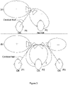
- the present examples may be viewed as building on the concept of the cardioid loudspeaker assembly 1001 described with reference to Fig. 1(a) .
- the loudspeakers may be mounted also with a certain angle relative to a z-direction where the z direction is defined as being an axis orthogonal to the upper plane of the enclosure.
- the signal processing for each loudspeaker may be a delay, a gain, and a filter, whose parameters have to be defined in function of the target directivity, directivity of the individual loudspeaker units and the mounting angles.
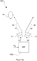
- the loudspeakers L1, L2, L3, L4 are arranged in a linear array, with each loudspeaker L1, L2, L3, L4 preferably being mounted within its own individual loudspeaker enclosure so that back radiation from each loudspeaker L1, L2, L3, L4 does not have a significant influence on other loudspeakers in the loudspeaker assembly 1.
- each loudspeaker L1, L2, L3, L4 has a respective principal radiating axis X1, X2, X3, X4 along which it produces sound.
- first angular offset between the first and second principal radiating axes X1, X2 there is a first angular offset between the first and second principal radiating axes X1, X2, a second angular offset between the first and third principal radiating axes X1, X3, and a third angular offset between the first and fourth principal radiating axes X1, X4.
- the distance between L1 and L4 is preferably no more than 50 cm.
- a first electrical signal E1 received by the first loudspeaker L1 is unfiltered, but the control unit is configured to filter second, third and fourth electrical signals E2, E3, E4 received (respectively) by the second, third and fourth loudspeakers L2, L3, L4 such that there is a first gain and phase difference between the first and second electrical signals E1, E2, a second gain and phase difference between the first and third electrical signals E1, E3, and a third gain and phase difference between the first and fourth electrical signals E1, E4.
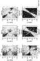
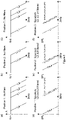
- Fig. 3 compares the operation of (a) the cardioid loudspeaker assembly 1001 of Fig. 1(a) with (b) the operation of the loudspeaker assembly 1 of Fig. 2 .
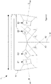
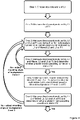
- Fig. 4 shows an example method for configuring the loudspeaker assembly 1 of Fig. 2 to obtain the operation shown in Fig. 3(b).
- Initial mounting angles of the loudspeakers L1, L2, L3, L4 may be chosen to provide a good starting point for obtaining cancellation of direct sound at each listening position, e.g. as shown in Fig. 2 .
- the loudspeakers L1, L2, L3, L4 preferably have a directivity index (according to the above definition) that is at least 6dB at a frequency of 3kHz, preferably so that loudspeaker L4 can be deemed to have an insignificant effect at listening position P1 and so that loudspeaker L1 can be deemed to have an insignificant effect at listening position P3 (as described below).
- Step 3 the direct sound produced by loudspeakers L2 and L3 at listening position P1 is measured, and a respective filter F2, F3 is defined for each of loudspeakers L2 and L3 so that the phase and amplitude of the direct sound produced by loudspeaker L1 and filtered loudspeakers L2, L3 at listening position P1 is cancelled in accordance with a predetermined cancelling condition (that requires the sound pressure level of direct sound produced by loudspeakers L1, L2, L3 at listening position P1 over 200 kHz-3kHz to be at least 12dB lower than the sound pressure level of direct sound produced by loudspeaker L1 at listening position P1).
- a predetermined cancelling condition that requires the sound pressure level of direct sound produced by loudspeakers L1, L2, L3 at listening position P1 over 200 kHz-3kHz to be at least 12dB lower than the sound pressure level of direct sound produced by loudspeaker L1 at listening position P1).
- Step 5 the direct sound produced by filtered loudspeakers L2 and L3 at listening position P3 is measured, and a filter F4 is defined for loudspeaker L4 so that the phase and amplitude of the filtered direct sound produced by loudspeakers L2, L3, L4 at listening position P3 is cancelled in accordance with the predetermined cancelling condition (that requires the sound pressure level of direct sound produced by loudspeakers L2, L3, L4 at listening position P3 over 200 kHz-3kHz to be at least 12dB lower than the sound pressure level of direct sound produced by loudspeakers L2, L3 at listening position P3).
- the effect of loudspeaker L1 at listening position P3 is ignored, since the angle of its principal radiating axis and its directivity index mean that the effect of direct sound produced by loudspeaker L1 at listening position P3 is deemed to be insignificant.
- Step 6 the direct sound produced by loudspeaker L1 and the filtered direct sound produced by loudspeakers L2, L3, L4 at listening position P2 is measured to determine whether the direct sound produced by loudspeakers L1, L2, L3, L4 at listening position P2 is cancelled in accordance with the predetermined cancelling condition (that requires the sound pressure level of direct sound produced by loudspeaker L1-L4 at listening position P2 over 200 kHz-3kHz to be at least 12dB lower than the sound pressure level of direct sound produced by loudspeaker L1 at listening position P2).
- the predetermined cancelling condition that requires the sound pressure level of direct sound produced by loudspeaker L1-L4 at listening position P2 over 200 kHz-3kHz to be at least 12dB lower than the sound pressure level of direct sound produced by loudspeaker L1 at listening position P2).
- direct sound is preferably measured in anechoic conditions, to avoid the influence of reflections.
- the sound of loudspeaker L1 is cancelled by the direct sound produced by filtered loudspeakers L2, L3.
- the direct sound produced by filtered loudspeaker L4 at listening position P1 is adequately low, and doesn't contribute significantly to the observation at position P1.
- the directivity index of the loudspeakers, the mounting angle and the electrical filtering are chosen as described above, so that cancellation of direct sound occurs at P1.
- filter 1 is a filter configured to cancel direct sound from L1 at sound at P3 and "filter 2" is a filter configured to cancel sound at P2.
- the response curve of the direct sound produced by L1 at P1 when filter 1 is applied is the substantially same as the unfiltered ("straight") direct sound produced by L1 at P3
- the response curve of the direct sound produced by L1 at P1 when filter 2 is applied is the substantially same as the unfiltered direct sound produced by L1 at P2.
Landscapes
- Engineering & Computer Science (AREA)
- Physics & Mathematics (AREA)
- Acoustics & Sound (AREA)
- Signal Processing (AREA)
- Health & Medical Sciences (AREA)
- Otolaryngology (AREA)
- General Health & Medical Sciences (AREA)
- Multimedia (AREA)
- Circuit For Audible Band Transducer (AREA)
- Obtaining Desirable Characteristics In Audible-Bandwidth Transducers (AREA)
Claims (11)
- Lautsprecheranordnung (1), die Folgendes umfasst:einen ersten Lautsprecher (L1), der ausgelegt ist, um ein erstes elektrisches Signal (E1) zu empfangen und Schall entlang einer ersten Hauptabstrahlachse (X1) auf Grundlage des ersten elektrischen Signals zu erzeugen;einen zweiten Lautsprecher (L2), der ausgelegt ist, um ein zweites elektrisches Signal (E2) zu empfangen und Schall entlang einer zweiten Hauptabstrahlachse (X2) auf Grundlage des zweiten elektrischen Signals zu erzeugen;einen dritten Lautsprecher (L3), der ausgelegt ist, um ein drittes elektrisches Signal zu empfangen und Schall entlang einer dritten Hauptabstrahlachse (X3) auf Grundlage des dritten elektrischen Signals (E3) zu erzeugen;einen vierten Lautsprecher (L4), der ausgelegt ist, um ein viertes elektrisches Signal (E4) zu empfangen und Schall entlang einer vierten Hauptabstrahlachse (X4) auf Grundlage des vierten elektrischen Signals zu erzeugen; undeine Steuereinheit, die ausgelegt ist, um das erste, zweite, dritte und vierte elektrische Signal jeweils auf Grundlage eines Ton repräsentierenden Eingangssignals zu erzeugen;wobei ein erster Winkelversatz zwischen der ersten und der zweiten Hauptabstrahlachse, ein zweiter Winkelversatz zwischen der ersten und der dritten Hauptabstrahlachse und ein dritter Winkelversatz zwischen der ersten und vierten Hauptabstrahlachse (X1, X4) vorliegt;wobei die Steuereinheit ausgelegt ist, um zumindest zwei von erstem, zweitem und drittem elektrischem Signal zu filtern, so dass eine erste Verstärkungs- und Phasendifferenz zwischen dem ersten und dem zweiten elektrischen Signal und eine zweite Verstärkungs- und Phasendifferenz zwischen dem ersten und dem dritten elektrischen Signal vorliegt, wobei die Steuereinheit ausgelegt ist, um das vierte elektrische Signal so zu filtern, dass eine dritte Verstärkungs- und Phasendifferenz zwischen dem ersten und dem vierten elektrischen Signal (E1, E4) vorliegt;wobei der erste, zweite und dritte Winkelversatz und die erste, zweite und dritte Verstärkungs- und Phasendifferenz so ausgelegt sind, dass bei Verwendung der Lautsprecheranordnung durch die Lautsprecher in der Lautsprecheranordnung erzeugter Direktschall gemäß einer vorbestimmten Auslöschbedingung jeweils an einer ersten Hörposition (P1), einer zweiten Hörposition (P2) und einer dritten Hörposition (P3) ausgelöscht wird;wobei die Lautsprecheranordnung ausgelegt ist, um in einem abgeschlossenen Raum verwendet zu werden;wobei die Lautsprecher in der Lautsprecheranordnung in einem Einzel-Lautsprecheranordnungsgehäuse (12) montiert sind, wobei sich die erste, die zweite und die dritte Hörposition außerhalb des Lautsprecheranordnungsgehäuses (12) befinden;wobei die Lautsprecher in einem linearen Array angeordnet sind;wobei die zwei Lautsprecher an den Enden des linearen Arrays Hauptabstrahlachsen aufweisen, die von entgegengesetzten Seitenflächen des Einzel-Lautsprecheranordnungsgehäuses (12) nach außen gerichtet sind, wobei die zwei Lautsprecher, die in Bezug auf die zwei Lautsprecher an den Enden des linearen Arrays innen vorliegen, einander zugewandt sind und Hauptabstrahlachsen aufweisen, die von einer Vorderseite des Einzel-Lautsprecheranordnungsgehäuses nach außen gerichtet sind, wobei die Vorderseite des Einzel-Lautsprecheranordnungsgehäuses (12) den Hörpositionen zugewandt ist; undwobei die erste, die zweite und die dritte Hörposition in einem linearen Array angeordnet sind.
- Lautsprecheranordnung nach Anspruch 1, wobei jeder Lautsprecher in der Lautsprecheranordnung einen Richtwirkungsindex aufweist, der bei einer Frequenz von 3 kHz zumindest 6 dB beträgt.
- Lautsprecheranordnung nach Anspruch 1 oder 2, wobei jede Verstärkungs- und Phasendifferenz unter 150 Hz null ist.
- Lautsprecheranordnung nach einem der vorangegangenen Ansprüche, wobei die vorbestimmte Auslöschungsbedingung an jeder Hörposition erfordert, dass in einem Frequenzbereich von 200 Hz bis 3 kHz der Schalldruckpegel von durch alle Lautsprecher in der Lautsprecheranordnung an den Hörpositionen erzeugtem Direktschall zumindest 12 dB niedriger ist als der Schalldruckpegel von durch eine Untergruppe der Lautsprecher in der Lautsprecheranordnung an der Hörposition erzeugter Direktschall.
- Lautsprecheranordnung nach einem der vorangegangenen Ansprüche, wobei:
die Lautsprecher in der Lautsprecheranordnung so angeordnet sind, dass zwischen jedem Lautsprecherpaar in der Lautsprecheranordnung ein Abstand von maximal 50 cm vorliegt. - Lautsprecheranordnung nach einem der vorangegangenen Ansprüche, wobei zwischen den Hauptachsen jedes Lautsprecherpaars in der Lautsprecheranordnung ein Winkelversatz vorliegt, der zumindest 30° beträgt.
- Lautsprecheranordnung nach einem der vorangegangenen Ansprüche, wobei das Lautsprecheranordnungsgehäuse balkenförmig ist und als Soundbar konfiguriert ist.
- Lautsprecheranordnung nach einem der vorangegangenen Ansprüche, wobei jeder Lautsprecher ein elektrodynamischer Lautsprecher ist, der Folgendes umfasst:eine Permanentmagnetanordnung, die Metallkomponenten und einen Permanentmagneten umfasst;eine Schwingspulenanordnung, die einen als Schwingspule bezeichneten Draht umfasst, der um ein als Schwingspulenwickelkörper bezeichnetes dünnes Rohr gewickelt ist;eine Membran;ein Chassis;ein Aufhängungssystem, das die Membran an dem Chassis aufhängt;wobei die Schwingspule ausgelegt ist, um mit einem statischen Magnetfeld des Permanentmagneten in Wechselwirkung zu treten, wenn elektrischer Strom durch die Schwingspule geleitet wird, so dass eine Wechselwirkung zwischen der Schwingspule und dem statischen Magnetfeld des Permanentmagneten in einer Bewegung der Schwingspule entlang einer vorbestimmten Achse resultiert.
- Lautsprecheranordnung nach einem der vorangegangenen Ansprüche, wobei jeder Lautsprecher in der Lautsprecheranordnung in seinem eigenen individuellen Lautsprechergehäuse montiert ist, so dass die Rückstrahlung von jedem Lautsprecher keinen signifikanten Einfluss auf andere Lautsprecher in der Lautsprecheranordnung hat.
- Verfahren zum Konfigurieren einer Lautsprecheranordnung, wobei die Lautsprecheranordnung Folgendes umfasst:einen ersten Lautsprecher (L1), der ausgelegt ist, um ein erstes elektrisches Signal (E1) zu empfangen und Schall entlang einer ersten Hauptabstrahlachse (X1) auf Grundlage des ersten elektrischen Signals zu erzeugen;einen zweiten Lautsprecher (L2), der ausgelegt ist, um ein zweites elektrisches Signal (E2) zu empfangen und Schall entlang einer zweiten Hauptabstrahlachse (X2) auf Grundlage des zweiten elektrischen Signals zu erzeugen;einen dritten Lautsprecher (L3), der ausgelegt ist, um ein drittes elektrisches Signal (E3) zu empfangen und Schall entlang einer dritten Hauptabstrahlachse (X3) auf Grundlage des dritten elektrischen Signals zu erzeugen;einen vierten Lautsprecher (L4), der ausgelegt ist, um ein viertes elektrisches Signal (E4) zu empfangen und Schall entlang einer vierten Hauptabstrahlachse (X4) auf Grundlage des vierten elektrischen Signals (E4) zu erzeugen; undeine Steuereinheit, die ausgelegt ist, um das erste, zweite, dritte und vierte elektrische Signal jeweils auf Grundlage eines Ton repräsentierenden Eingangssignals zu erzeugen;wobei ein erster Winkelversatz zwischen der ersten und der zweiten Hauptabstrahlachse, ein zweiter Winkelversatz zwischen der ersten und der dritten Hauptabstrahlachse und ein dritter Winkelversatz zwischen der ersten und vierten Hauptabstrahlachse (X1, X4) vorliegt;wobei die Steuereinheit ausgelegt ist, um zumindest zwei von erstem, zweitem und drittem elektrischem Signal zu filtern, so dass eine erste Verstärkungs- und Phasendifferenz zwischen dem ersten und dem zweiten elektrischen Signal und eine zweite Verstärkungs- und Phasendifferenz zwischen dem ersten und dem dritten elektrischen Signal vorliegt, wobei die Steuereinheit ausgelegt ist, um das vierte elektrische Signal so zu filtern, dass eine dritte Verstärkungs- und Phasendifferenz zwischen dem ersten und dem vierten elektrischen Signal (E1, E4) vorliegt;wobei die Lautsprecheranordnung ausgelegt ist, um in einem abgeschlossenen Raum verwendet zu werden;wobei das Verfahren das Einstellen des ersten, des zweiten und des dritten Winkelversatzes und der ersten, der zweiten und der dritten Verstärkungs- und Phasendifferenz umfasst, so dass bei Verwendung der Lautsprecheranordnung durch die Lautsprecher in der Lautsprecheranordnung erzeugter Direktschall gemäß einer vorbestimmten Auslöschbedingung an einer ersten Hörposition (P1), einer zweiten Hörposition (P2) und einer dritten Hörposition (P3) jeweils ausgelöscht wird;wobei die Lautsprecher in der Lautsprecheranordnung in einem Einzel-Lautsprecheranordnungsgehäuse (12) montiert sind, wobei sich die erste, die zweite und die dritte Hörposition außerhalb des Lautsprecheranordnungsgehäuses (12) befinden;wobei die Lautsprecher in einem linearen Array angeordnet sind;wobei die zwei Lautsprecher an den Enden des linearen Arrays Hauptabstrahlachsen aufweisen, die von entgegengesetzten Seitenflächen des Einzel-Lautsprecheranordnungsgehäuses (12) nach außen gerichtet sind, wobei die zwei Lautsprecher, die in Bezug auf die zwei Lautsprecher an den Enden des linearen Arrays innen vorliegen, einander zugewandt sind und Hauptabstrahlachsen aufweisen, die von einer Vorderseite des Einzel-Lautsprecheranordnungsgehäuses nach außen gerichtet sind, wobei die Vorderseite des Einzel-Lautsprecheranordnungsgehäuses (12) den Hörpositionen zugewandt ist; undwobei die erste, die zweite und die dritte Hörposition in einem linearen Array angeordnet sind.
- Verfahren nach Anspruch 10, wobei das Konfigurieren der Lautsprecheranordnung auch Folgendes umfasst:(i) an einer ersten der Hörpositionen das Messen von durch eine erste Untergruppe der Lautsprecher in der Lautsprecheranordnung erzeugtem Direktschall und auf Grundlage des gemessenen Direktschalls das Einstellen einer oder mehrerer der Verstärkungs- und Phasendifferenzen, so dass durch mehrere Lautsprecher in der Lautsprecheranordnung erzeugter Direktschall gemäß einer vorbestimmten Auslöschbedingung an der ersten Hörposition ausgelöscht wird;(ii) an einer zweiten der Hörpositionen das Messen von durch mehrere Lautsprecher in der Lautsprecheranordnung erzeugtem Direktschall und Bewerten, ob der durch die mehreren Lautsprecher erzeugte Direktschall gemäß der vorbestimmten Auslöschbedingung an der zweiten Hörposition ausgelöscht wird;(iii) wenn der durch die mehreren Lautsprecher erzeugte Direktschall nicht gemäß der vorbestimmten Auslöschbedingung an der zweiten Hörposition ausgelöscht wird, das Einstellen eines oder mehrerer der Winkelversätze und Rückkehr zu Schritt (i);(iv) an einer dritten der Hörpositionen das Messen von durch eine zweite Untergruppe der Lautsprecher in der Lautsprecheranordnung erzeugtem Direktschall und auf Grundlage des gemessenen Direktschalls das Einstellen der dritten Verstärkungs- und Phasendifferenz, so dass von mehreren Lautsprechern in der Lautsprecheranordnung erzeugter Direktschall gemäß einer vorbestimmten Auslöschbedingung an der dritten Hörposition ausgelöscht wird;(v) an der zweiten Hörposition das Messen von durch mehrere Lautsprecher in der Lautsprecheranordnung erzeugtem Direktschall und Bewerten, ob der durch die mehreren Lautsprecher erzeugte Direktschall gemäß der vorbestimmten Auslöschbedingung an der zweiten Hörposition ausgelöscht wird;(vi) wenn der durch die mehreren Lautsprecher erzeugte Direktschall nicht gemäß der vorbestimmten Auslöschbedingung an der zweiten Hörposition ausgelöscht wird, das Einstellen eines oder mehrerer der Winkelversätze und Rückkehr zu Schritt (i).
Applications Claiming Priority (2)
| Application Number | Priority Date | Filing Date | Title |
|---|---|---|---|
| GB1522136.9A GB2545439A (en) | 2015-12-15 | 2015-12-15 | Loudspeaker assemblies and associated methods |
| PCT/EP2016/078631 WO2017102278A1 (en) | 2015-12-15 | 2016-11-24 | Loudspeaker assemblies and associated methods |
Publications (2)
| Publication Number | Publication Date |
|---|---|
| EP3391663A1 EP3391663A1 (de) | 2018-10-24 |
| EP3391663B1 true EP3391663B1 (de) | 2022-11-02 |
Family
ID=55274803
Family Applications (1)
| Application Number | Title | Priority Date | Filing Date |
|---|---|---|---|
| EP16800982.7A Active EP3391663B1 (de) | 2015-12-15 | 2016-11-24 | Lautsprecherbaugruppen und zugehörige verfahren |
Country Status (5)
| Country | Link |
|---|---|
| US (1) | US10880648B2 (de) |
| EP (1) | EP3391663B1 (de) |
| CN (1) | CN108476359B (de) |
| GB (1) | GB2545439A (de) |
| WO (1) | WO2017102278A1 (de) |
Families Citing this family (8)
| Publication number | Priority date | Publication date | Assignee | Title |
|---|---|---|---|---|
| WO2020181288A1 (en) * | 2019-03-07 | 2020-09-10 | Polk Audio, Llc | Active cancellation of a height-channel soundbar array's forward sound radiation |
| US20210274282A1 (en) * | 2019-06-17 | 2021-09-02 | Audio Accessories Group, LLC | Sound bar with various couplings |
| US11463811B2 (en) * | 2020-04-10 | 2022-10-04 | Harman International Industries, Incorporated | Speaker system with overhead sound projection |
| CN111787478A (zh) * | 2020-06-23 | 2020-10-16 | 北京小米移动软件有限公司 | 设备控制方法及装置 |
| GB2600538B (en) * | 2020-09-09 | 2023-04-05 | Tymphany Worldwide Enterprises Ltd | Method of providing audio in a vehicle, and an audio apparatus for a vehicle |
| DE102021203632A1 (de) | 2021-04-13 | 2022-10-13 | Kaetel Systems Gmbh | Lautsprecher, Signalprozessor, Verfahren zum Herstellen des Lautsprechers oder Verfahren zum Betreiben des Signalprozessors unter Verwendung einer Dual-Mode-Signalerzeugung mit zwei Schallerzeugern |
| GB2627479A (en) | 2023-02-23 | 2024-08-28 | Meridian Audio Ltd | Generating audio driving signals for the production of simultaneous stereo sound stages |
| US20250274711A1 (en) * | 2024-02-28 | 2025-08-28 | Gilberto Torres Ayala | Collider system for the generation and reproduction of signals from trisonic audio with zero latency |
Citations (2)
| Publication number | Priority date | Publication date | Assignee | Title |
|---|---|---|---|---|
| US5809150A (en) * | 1995-06-28 | 1998-09-15 | Eberbach; Steven J. | Surround sound loudspeaker system |
| EP2891338A1 (de) * | 2012-08-31 | 2015-07-08 | Dolby Laboratories Licensing Corporation | System zur erzeugung und wiedergabe von objektbasiertem audio in verschiedenen zuhörumgebungen |
Family Cites Families (14)
| Publication number | Priority date | Publication date | Assignee | Title |
|---|---|---|---|---|
| US5870484A (en) | 1995-09-05 | 1999-02-09 | Greenberger; Hal | Loudspeaker array with signal dependent radiation pattern |
| US5809153A (en) * | 1996-12-04 | 1998-09-15 | Bose Corporation | Electroacoustical transducing |
| JP3422281B2 (ja) * | 1999-04-08 | 2003-06-30 | ヤマハ株式会社 | 指向性拡声装置 |
| US20040109570A1 (en) * | 2002-06-21 | 2004-06-10 | Sunil Bharitkar | System and method for selective signal cancellation for multiple-listener audio applications |
| ITBS20050006A1 (it) * | 2005-01-28 | 2006-07-29 | Outline Di Noselli G & C S N C | Elemento diffusore del suono per formare sistemi di diffusori in linea verticale a direttivita' regolabile sia orizzontalmente sia verticalmente |
| US9100748B2 (en) * | 2007-05-04 | 2015-08-04 | Bose Corporation | System and method for directionally radiating sound |
| US20080273722A1 (en) * | 2007-05-04 | 2008-11-06 | Aylward J Richard | Directionally radiating sound in a vehicle |
| CN201138867Y (zh) * | 2008-01-09 | 2008-10-22 | 龚立风 | 一种有源线性阵列音响 |
| JP5643657B2 (ja) * | 2008-03-13 | 2014-12-17 | コーニンクレッカ フィリップス エヌ ヴェ | スピーカアレイ及びスピーカアレイに関する駆動装置構成 |
| JP4557054B2 (ja) * | 2008-06-20 | 2010-10-06 | 株式会社デンソー | 車載用立体音響装置 |
| GB0821999D0 (en) * | 2008-12-02 | 2009-01-07 | Pss Belgium Nv | Method and apparatus for improved directivity of an acoustic antenna |
| CN101588524A (zh) * | 2009-07-08 | 2009-11-25 | 电子科技大学 | 指向可调式微型声频定向扬声器系统 |
| CN202143200U (zh) * | 2011-05-20 | 2012-02-08 | 广州励华声光科技有限公司 | 可变指向性音箱 |
| CN202310093U (zh) * | 2011-09-27 | 2012-07-04 | 清华大学 | 锯齿状阵列式压电扬声器组 |
-
2015
- 2015-12-15 GB GB1522136.9A patent/GB2545439A/en not_active Withdrawn
-
2016
- 2016-11-24 US US16/062,740 patent/US10880648B2/en active Active
- 2016-11-24 EP EP16800982.7A patent/EP3391663B1/de active Active
- 2016-11-24 CN CN201680074754.9A patent/CN108476359B/zh active Active
- 2016-11-24 WO PCT/EP2016/078631 patent/WO2017102278A1/en not_active Ceased
Patent Citations (3)
| Publication number | Priority date | Publication date | Assignee | Title |
|---|---|---|---|---|
| US5809150A (en) * | 1995-06-28 | 1998-09-15 | Eberbach; Steven J. | Surround sound loudspeaker system |
| EP2891338A1 (de) * | 2012-08-31 | 2015-07-08 | Dolby Laboratories Licensing Corporation | System zur erzeugung und wiedergabe von objektbasiertem audio in verschiedenen zuhörumgebungen |
| US20150223002A1 (en) * | 2012-08-31 | 2015-08-06 | Dolby Laboratories Licensing Corporation | System for Rendering and Playback of Object Based Audio in Various Listening Environments |
Also Published As
| Publication number | Publication date |
|---|---|
| US20200169808A1 (en) | 2020-05-28 |
| EP3391663A1 (de) | 2018-10-24 |
| US10880648B2 (en) | 2020-12-29 |
| GB201522136D0 (en) | 2016-01-27 |
| WO2017102278A1 (en) | 2017-06-22 |
| GB2545439A (en) | 2017-06-21 |
| CN108476359B (zh) | 2022-02-15 |
| CN108476359A (zh) | 2018-08-31 |
Similar Documents
| Publication | Publication Date | Title |
|---|---|---|
| EP3391663B1 (de) | Lautsprecherbaugruppen und zugehörige verfahren | |
| US10038963B2 (en) | Speaker device and audio signal processing method | |
| CN102804814B (zh) | 多通道声音重放方法和设备 | |
| US20120269368A1 (en) | Loudspeaker array system | |
| JP2005159518A (ja) | アレースピーカ装置 | |
| KR20160001712A (ko) | 음향 신호의 렌더링 방법, 장치 및 컴퓨터 판독 가능한 기록 매체 | |
| JP2018527808A (ja) | サウンドバー | |
| US10945090B1 (en) | Surround sound rendering based on room acoustics | |
| KR102353871B1 (ko) | 가변 음향 라우드스피커 | |
| KR20140007794A (ko) | 어레이 라우드스피커 시스템 | |
| CN107079217A (zh) | 具有窄分散度的扩音器 | |
| EP3089476A1 (de) | Soundsystem | |
| US9843864B2 (en) | Method for operating an arrangement of sound transducers according to the wave field synthesis principle | |
| US4847904A (en) | Ambient imaging loudspeaker system | |
| Lee et al. | HRTF measurement for accurate sound localization cues | |
| US10440495B2 (en) | Virtual localization of sound | |
| CN107333206B (zh) | 整体式音箱及其控制方法 | |
| CN119318161A (zh) | 定向声音产生设备 | |
| JP4625756B2 (ja) | ラウドスピーカのアレイシステム | |
| EP3790287A1 (de) | Lautsprechersystem mit aktiver steuerung der richtcharakteristik | |
| JP7160312B2 (ja) | 音響システム | |
| Sporer et al. | Wave Field Synthesis | |
| US9729992B1 (en) | Front loudspeaker directivity for surround sound systems | |
| Frank et al. | Simple technical prediction of phantom source widening | |
| RU2575883C2 (ru) | Акустическая система и способ ее работы |
Legal Events
| Date | Code | Title | Description |
|---|---|---|---|
| STAA | Information on the status of an ep patent application or granted ep patent |
Free format text: STATUS: UNKNOWN |
|
| STAA | Information on the status of an ep patent application or granted ep patent |
Free format text: STATUS: THE INTERNATIONAL PUBLICATION HAS BEEN MADE |
|
| PUAI | Public reference made under article 153(3) epc to a published international application that has entered the european phase |
Free format text: ORIGINAL CODE: 0009012 |
|
| STAA | Information on the status of an ep patent application or granted ep patent |
Free format text: STATUS: REQUEST FOR EXAMINATION WAS MADE |
|
| 17P | Request for examination filed |
Effective date: 20180713 |
|
| AK | Designated contracting states |
Kind code of ref document: A1 Designated state(s): AL AT BE BG CH CY CZ DE DK EE ES FI FR GB GR HR HU IE IS IT LI LT LU LV MC MK MT NL NO PL PT RO RS SE SI SK SM TR |
|
| AX | Request for extension of the european patent |
Extension state: BA ME |
|
| DAV | Request for validation of the european patent (deleted) | ||
| DAX | Request for extension of the european patent (deleted) | ||
| STAA | Information on the status of an ep patent application or granted ep patent |
Free format text: STATUS: EXAMINATION IS IN PROGRESS |
|
| 17Q | First examination report despatched |
Effective date: 20200807 |
|
| GRAP | Despatch of communication of intention to grant a patent |
Free format text: ORIGINAL CODE: EPIDOSNIGR1 |
|
| STAA | Information on the status of an ep patent application or granted ep patent |
Free format text: STATUS: GRANT OF PATENT IS INTENDED |
|
| INTG | Intention to grant announced |
Effective date: 20220622 |
|
| GRAS | Grant fee paid |
Free format text: ORIGINAL CODE: EPIDOSNIGR3 |
|
| GRAA | (expected) grant |
Free format text: ORIGINAL CODE: 0009210 |
|
| STAA | Information on the status of an ep patent application or granted ep patent |
Free format text: STATUS: THE PATENT HAS BEEN GRANTED |
|
| AK | Designated contracting states |
Kind code of ref document: B1 Designated state(s): AL AT BE BG CH CY CZ DE DK EE ES FI FR GB GR HR HU IE IS IT LI LT LU LV MC MK MT NL NO PL PT RO RS SE SI SK SM TR |
|
| REG | Reference to a national code |
Ref country code: GB Ref legal event code: FG4D |
|
| REG | Reference to a national code |
Ref country code: CH Ref legal event code: EP Ref country code: AT Ref legal event code: REF Ref document number: 1529642 Country of ref document: AT Kind code of ref document: T Effective date: 20221115 |
|
| REG | Reference to a national code |
Ref country code: DE Ref legal event code: R096 Ref document number: 602016076084 Country of ref document: DE |
|
| REG | Reference to a national code |
Ref country code: IE Ref legal event code: FG4D |
|
| REG | Reference to a national code |
Ref country code: LT Ref legal event code: MG9D |
|
| REG | Reference to a national code |
Ref country code: NL Ref legal event code: MP Effective date: 20221102 |
|
| REG | Reference to a national code |
Ref country code: AT Ref legal event code: MK05 Ref document number: 1529642 Country of ref document: AT Kind code of ref document: T Effective date: 20221102 |
|
| PG25 | Lapsed in a contracting state [announced via postgrant information from national office to epo] |
Ref country code: SE Free format text: LAPSE BECAUSE OF FAILURE TO SUBMIT A TRANSLATION OF THE DESCRIPTION OR TO PAY THE FEE WITHIN THE PRESCRIBED TIME-LIMIT Effective date: 20221102 Ref country code: PT Free format text: LAPSE BECAUSE OF FAILURE TO SUBMIT A TRANSLATION OF THE DESCRIPTION OR TO PAY THE FEE WITHIN THE PRESCRIBED TIME-LIMIT Effective date: 20230302 Ref country code: NO Free format text: LAPSE BECAUSE OF FAILURE TO SUBMIT A TRANSLATION OF THE DESCRIPTION OR TO PAY THE FEE WITHIN THE PRESCRIBED TIME-LIMIT Effective date: 20230202 Ref country code: LT Free format text: LAPSE BECAUSE OF FAILURE TO SUBMIT A TRANSLATION OF THE DESCRIPTION OR TO PAY THE FEE WITHIN THE PRESCRIBED TIME-LIMIT Effective date: 20221102 Ref country code: FI Free format text: LAPSE BECAUSE OF FAILURE TO SUBMIT A TRANSLATION OF THE DESCRIPTION OR TO PAY THE FEE WITHIN THE PRESCRIBED TIME-LIMIT Effective date: 20221102 Ref country code: ES Free format text: LAPSE BECAUSE OF FAILURE TO SUBMIT A TRANSLATION OF THE DESCRIPTION OR TO PAY THE FEE WITHIN THE PRESCRIBED TIME-LIMIT Effective date: 20221102 Ref country code: AT Free format text: LAPSE BECAUSE OF FAILURE TO SUBMIT A TRANSLATION OF THE DESCRIPTION OR TO PAY THE FEE WITHIN THE PRESCRIBED TIME-LIMIT Effective date: 20221102 |
|
| PG25 | Lapsed in a contracting state [announced via postgrant information from national office to epo] |
Ref country code: RS Free format text: LAPSE BECAUSE OF FAILURE TO SUBMIT A TRANSLATION OF THE DESCRIPTION OR TO PAY THE FEE WITHIN THE PRESCRIBED TIME-LIMIT Effective date: 20221102 Ref country code: PL Free format text: LAPSE BECAUSE OF FAILURE TO SUBMIT A TRANSLATION OF THE DESCRIPTION OR TO PAY THE FEE WITHIN THE PRESCRIBED TIME-LIMIT Effective date: 20221102 Ref country code: LV Free format text: LAPSE BECAUSE OF FAILURE TO SUBMIT A TRANSLATION OF THE DESCRIPTION OR TO PAY THE FEE WITHIN THE PRESCRIBED TIME-LIMIT Effective date: 20221102 Ref country code: IS Free format text: LAPSE BECAUSE OF FAILURE TO SUBMIT A TRANSLATION OF THE DESCRIPTION OR TO PAY THE FEE WITHIN THE PRESCRIBED TIME-LIMIT Effective date: 20230302 Ref country code: HR Free format text: LAPSE BECAUSE OF FAILURE TO SUBMIT A TRANSLATION OF THE DESCRIPTION OR TO PAY THE FEE WITHIN THE PRESCRIBED TIME-LIMIT Effective date: 20221102 Ref country code: GR Free format text: LAPSE BECAUSE OF FAILURE TO SUBMIT A TRANSLATION OF THE DESCRIPTION OR TO PAY THE FEE WITHIN THE PRESCRIBED TIME-LIMIT Effective date: 20230203 |
|
| P01 | Opt-out of the competence of the unified patent court (upc) registered |
Effective date: 20230502 |
|
| PG25 | Lapsed in a contracting state [announced via postgrant information from national office to epo] |
Ref country code: NL Free format text: LAPSE BECAUSE OF FAILURE TO SUBMIT A TRANSLATION OF THE DESCRIPTION OR TO PAY THE FEE WITHIN THE PRESCRIBED TIME-LIMIT Effective date: 20221102 |
|
| REG | Reference to a national code |
Ref country code: CH Ref legal event code: PL |
|
| PG25 | Lapsed in a contracting state [announced via postgrant information from national office to epo] |
Ref country code: SM Free format text: LAPSE BECAUSE OF FAILURE TO SUBMIT A TRANSLATION OF THE DESCRIPTION OR TO PAY THE FEE WITHIN THE PRESCRIBED TIME-LIMIT Effective date: 20221102 Ref country code: RO Free format text: LAPSE BECAUSE OF FAILURE TO SUBMIT A TRANSLATION OF THE DESCRIPTION OR TO PAY THE FEE WITHIN THE PRESCRIBED TIME-LIMIT Effective date: 20221102 Ref country code: LI Free format text: LAPSE BECAUSE OF NON-PAYMENT OF DUE FEES Effective date: 20221130 Ref country code: EE Free format text: LAPSE BECAUSE OF FAILURE TO SUBMIT A TRANSLATION OF THE DESCRIPTION OR TO PAY THE FEE WITHIN THE PRESCRIBED TIME-LIMIT Effective date: 20221102 Ref country code: DK Free format text: LAPSE BECAUSE OF FAILURE TO SUBMIT A TRANSLATION OF THE DESCRIPTION OR TO PAY THE FEE WITHIN THE PRESCRIBED TIME-LIMIT Effective date: 20221102 Ref country code: CZ Free format text: LAPSE BECAUSE OF FAILURE TO SUBMIT A TRANSLATION OF THE DESCRIPTION OR TO PAY THE FEE WITHIN THE PRESCRIBED TIME-LIMIT Effective date: 20221102 Ref country code: CH Free format text: LAPSE BECAUSE OF NON-PAYMENT OF DUE FEES Effective date: 20221130 |
|
| REG | Reference to a national code |
Ref country code: DE Ref legal event code: R097 Ref document number: 602016076084 Country of ref document: DE |
|
| PG25 | Lapsed in a contracting state [announced via postgrant information from national office to epo] |
Ref country code: SK Free format text: LAPSE BECAUSE OF FAILURE TO SUBMIT A TRANSLATION OF THE DESCRIPTION OR TO PAY THE FEE WITHIN THE PRESCRIBED TIME-LIMIT Effective date: 20221102 Ref country code: LU Free format text: LAPSE BECAUSE OF NON-PAYMENT OF DUE FEES Effective date: 20221124 Ref country code: AL Free format text: LAPSE BECAUSE OF FAILURE TO SUBMIT A TRANSLATION OF THE DESCRIPTION OR TO PAY THE FEE WITHIN THE PRESCRIBED TIME-LIMIT Effective date: 20221102 |
|
| PLBE | No opposition filed within time limit |
Free format text: ORIGINAL CODE: 0009261 |
|
| STAA | Information on the status of an ep patent application or granted ep patent |
Free format text: STATUS: NO OPPOSITION FILED WITHIN TIME LIMIT |
|
| 26N | No opposition filed |
Effective date: 20230803 |
|
| PG25 | Lapsed in a contracting state [announced via postgrant information from national office to epo] |
Ref country code: IE Free format text: LAPSE BECAUSE OF NON-PAYMENT OF DUE FEES Effective date: 20221124 |
|
| PG25 | Lapsed in a contracting state [announced via postgrant information from national office to epo] |
Ref country code: SI Free format text: LAPSE BECAUSE OF FAILURE TO SUBMIT A TRANSLATION OF THE DESCRIPTION OR TO PAY THE FEE WITHIN THE PRESCRIBED TIME-LIMIT Effective date: 20221102 |
|
| PG25 | Lapsed in a contracting state [announced via postgrant information from national office to epo] |
Ref country code: HU Free format text: LAPSE BECAUSE OF FAILURE TO SUBMIT A TRANSLATION OF THE DESCRIPTION OR TO PAY THE FEE WITHIN THE PRESCRIBED TIME-LIMIT; INVALID AB INITIO Effective date: 20161124 |
|
| PG25 | Lapsed in a contracting state [announced via postgrant information from national office to epo] |
Ref country code: CY Free format text: LAPSE BECAUSE OF FAILURE TO SUBMIT A TRANSLATION OF THE DESCRIPTION OR TO PAY THE FEE WITHIN THE PRESCRIBED TIME-LIMIT Effective date: 20221102 |
|
| PG25 | Lapsed in a contracting state [announced via postgrant information from national office to epo] |
Ref country code: MK Free format text: LAPSE BECAUSE OF FAILURE TO SUBMIT A TRANSLATION OF THE DESCRIPTION OR TO PAY THE FEE WITHIN THE PRESCRIBED TIME-LIMIT Effective date: 20221102 Ref country code: IT Free format text: LAPSE BECAUSE OF FAILURE TO SUBMIT A TRANSLATION OF THE DESCRIPTION OR TO PAY THE FEE WITHIN THE PRESCRIBED TIME-LIMIT Effective date: 20221102 |
|
| PG25 | Lapsed in a contracting state [announced via postgrant information from national office to epo] |
Ref country code: MC Free format text: LAPSE BECAUSE OF FAILURE TO SUBMIT A TRANSLATION OF THE DESCRIPTION OR TO PAY THE FEE WITHIN THE PRESCRIBED TIME-LIMIT Effective date: 20221102 |
|
| PG25 | Lapsed in a contracting state [announced via postgrant information from national office to epo] |
Ref country code: TR Free format text: LAPSE BECAUSE OF FAILURE TO SUBMIT A TRANSLATION OF THE DESCRIPTION OR TO PAY THE FEE WITHIN THE PRESCRIBED TIME-LIMIT Effective date: 20221102 Ref country code: MC Free format text: LAPSE BECAUSE OF FAILURE TO SUBMIT A TRANSLATION OF THE DESCRIPTION OR TO PAY THE FEE WITHIN THE PRESCRIBED TIME-LIMIT Effective date: 20221102 |
|
| PG25 | Lapsed in a contracting state [announced via postgrant information from national office to epo] |
Ref country code: BG Free format text: LAPSE BECAUSE OF FAILURE TO SUBMIT A TRANSLATION OF THE DESCRIPTION OR TO PAY THE FEE WITHIN THE PRESCRIBED TIME-LIMIT Effective date: 20221102 |
|
| PG25 | Lapsed in a contracting state [announced via postgrant information from national office to epo] |
Ref country code: MT Free format text: LAPSE BECAUSE OF FAILURE TO SUBMIT A TRANSLATION OF THE DESCRIPTION OR TO PAY THE FEE WITHIN THE PRESCRIBED TIME-LIMIT Effective date: 20221102 |
|
| PGFP | Annual fee paid to national office [announced via postgrant information from national office to epo] |
Ref country code: DE Payment date: 20241125 Year of fee payment: 9 |
|
| PGFP | Annual fee paid to national office [announced via postgrant information from national office to epo] |
Ref country code: BE Payment date: 20241202 Year of fee payment: 9 |
|
| PGFP | Annual fee paid to national office [announced via postgrant information from national office to epo] |
Ref country code: FR Payment date: 20241121 Year of fee payment: 9 |
|
| PGFP | Annual fee paid to national office [announced via postgrant information from national office to epo] |
Ref country code: GB Payment date: 20251119 Year of fee payment: 10 |