EP3391663B1 - Loudspeaker assemblies and associated methods - Google Patents
Loudspeaker assemblies and associated methods Download PDFInfo
- Publication number
- EP3391663B1 EP3391663B1 EP16800982.7A EP16800982A EP3391663B1 EP 3391663 B1 EP3391663 B1 EP 3391663B1 EP 16800982 A EP16800982 A EP 16800982A EP 3391663 B1 EP3391663 B1 EP 3391663B1
- Authority
- EP
- European Patent Office
- Prior art keywords
- loudspeaker
- loudspeaker assembly
- loudspeakers
- direct sound
- listening position
- Prior art date
- Legal status (The legal status is an assumption and is not a legal conclusion. Google has not performed a legal analysis and makes no representation as to the accuracy of the status listed.)
- Active
Links
Images

Classifications
-
- H—ELECTRICITY
- H04—ELECTRIC COMMUNICATION TECHNIQUE
- H04R—LOUDSPEAKERS, MICROPHONES, GRAMOPHONE PICK-UPS OR LIKE ACOUSTIC ELECTROMECHANICAL TRANSDUCERS; ELECTRIC HEARING AIDS; PUBLIC ADDRESS SYSTEMS
- H04R5/00—Stereophonic arrangements
- H04R5/02—Spatial or constructional arrangements of loudspeakers
-
- H—ELECTRICITY
- H04—ELECTRIC COMMUNICATION TECHNIQUE
- H04R—LOUDSPEAKERS, MICROPHONES, GRAMOPHONE PICK-UPS OR LIKE ACOUSTIC ELECTROMECHANICAL TRANSDUCERS; ELECTRIC HEARING AIDS; PUBLIC ADDRESS SYSTEMS
- H04R1/00—Details of transducers, loudspeakers or microphones
- H04R1/02—Casings; Cabinets ; Supports therefor; Mountings therein
- H04R1/025—Arrangements for fixing loudspeaker transducers, e.g. in a box, furniture
-
- H—ELECTRICITY
- H04—ELECTRIC COMMUNICATION TECHNIQUE
- H04R—LOUDSPEAKERS, MICROPHONES, GRAMOPHONE PICK-UPS OR LIKE ACOUSTIC ELECTROMECHANICAL TRANSDUCERS; ELECTRIC HEARING AIDS; PUBLIC ADDRESS SYSTEMS
- H04R1/00—Details of transducers, loudspeakers or microphones
- H04R1/20—Arrangements for obtaining desired frequency or directional characteristics
- H04R1/32—Arrangements for obtaining desired frequency or directional characteristics for obtaining desired directional characteristic only
- H04R1/40—Arrangements for obtaining desired frequency or directional characteristics for obtaining desired directional characteristic only by combining a number of identical transducers
- H04R1/403—Arrangements for obtaining desired frequency or directional characteristics for obtaining desired directional characteristic only by combining a number of identical transducers loud-speakers
-
- H—ELECTRICITY
- H04—ELECTRIC COMMUNICATION TECHNIQUE
- H04R—LOUDSPEAKERS, MICROPHONES, GRAMOPHONE PICK-UPS OR LIKE ACOUSTIC ELECTROMECHANICAL TRANSDUCERS; ELECTRIC HEARING AIDS; PUBLIC ADDRESS SYSTEMS
- H04R29/00—Monitoring arrangements; Testing arrangements
- H04R29/001—Monitoring arrangements; Testing arrangements for loudspeakers
- H04R29/002—Loudspeaker arrays
-
- H—ELECTRICITY
- H04—ELECTRIC COMMUNICATION TECHNIQUE
- H04R—LOUDSPEAKERS, MICROPHONES, GRAMOPHONE PICK-UPS OR LIKE ACOUSTIC ELECTROMECHANICAL TRANSDUCERS; ELECTRIC HEARING AIDS; PUBLIC ADDRESS SYSTEMS
- H04R3/00—Circuits for transducers
- H04R3/12—Circuits for transducers for distributing signals to two or more loudspeakers
-
- H—ELECTRICITY
- H04—ELECTRIC COMMUNICATION TECHNIQUE
- H04R—LOUDSPEAKERS, MICROPHONES, GRAMOPHONE PICK-UPS OR LIKE ACOUSTIC ELECTROMECHANICAL TRANSDUCERS; ELECTRIC HEARING AIDS; PUBLIC ADDRESS SYSTEMS
- H04R5/00—Stereophonic arrangements
- H04R5/04—Circuit arrangements, e.g. for selective connection of amplifier inputs/outputs to loudspeakers, for loudspeaker detection, or for adaptation of settings to personal preferences or hearing impairments
-
- H—ELECTRICITY
- H04—ELECTRIC COMMUNICATION TECHNIQUE
- H04R—LOUDSPEAKERS, MICROPHONES, GRAMOPHONE PICK-UPS OR LIKE ACOUSTIC ELECTROMECHANICAL TRANSDUCERS; ELECTRIC HEARING AIDS; PUBLIC ADDRESS SYSTEMS
- H04R7/00—Diaphragms for electromechanical transducers; Cones
- H04R7/02—Diaphragms for electromechanical transducers; Cones characterised by the construction
- H04R7/12—Non-planar diaphragms or cones
-
- H—ELECTRICITY
- H04—ELECTRIC COMMUNICATION TECHNIQUE
- H04R—LOUDSPEAKERS, MICROPHONES, GRAMOPHONE PICK-UPS OR LIKE ACOUSTIC ELECTROMECHANICAL TRANSDUCERS; ELECTRIC HEARING AIDS; PUBLIC ADDRESS SYSTEMS
- H04R7/00—Diaphragms for electromechanical transducers; Cones
- H04R7/16—Mounting or tensioning of diaphragms or cones
- H04R7/18—Mounting or tensioning of diaphragms or cones at the periphery
-
- H—ELECTRICITY
- H04—ELECTRIC COMMUNICATION TECHNIQUE
- H04R—LOUDSPEAKERS, MICROPHONES, GRAMOPHONE PICK-UPS OR LIKE ACOUSTIC ELECTROMECHANICAL TRANSDUCERS; ELECTRIC HEARING AIDS; PUBLIC ADDRESS SYSTEMS
- H04R9/00—Transducers of moving-coil, moving-strip, or moving-wire type
- H04R9/02—Details
- H04R9/025—Magnetic circuit
-
- H—ELECTRICITY
- H04—ELECTRIC COMMUNICATION TECHNIQUE
- H04R—LOUDSPEAKERS, MICROPHONES, GRAMOPHONE PICK-UPS OR LIKE ACOUSTIC ELECTROMECHANICAL TRANSDUCERS; ELECTRIC HEARING AIDS; PUBLIC ADDRESS SYSTEMS
- H04R9/00—Transducers of moving-coil, moving-strip, or moving-wire type
- H04R9/06—Loudspeakers
-
- H—ELECTRICITY
- H04—ELECTRIC COMMUNICATION TECHNIQUE
- H04S—STEREOPHONIC SYSTEMS
- H04S7/00—Indicating arrangements; Control arrangements, e.g. balance control
- H04S7/30—Control circuits for electronic adaptation of the sound field
-
- H—ELECTRICITY
- H04—ELECTRIC COMMUNICATION TECHNIQUE
- H04S—STEREOPHONIC SYSTEMS
- H04S7/00—Indicating arrangements; Control arrangements, e.g. balance control
- H04S7/30—Control circuits for electronic adaptation of the sound field
- H04S7/302—Electronic adaptation of stereophonic sound system to listener position or orientation
-
- H—ELECTRICITY
- H04—ELECTRIC COMMUNICATION TECHNIQUE
- H04R—LOUDSPEAKERS, MICROPHONES, GRAMOPHONE PICK-UPS OR LIKE ACOUSTIC ELECTROMECHANICAL TRANSDUCERS; ELECTRIC HEARING AIDS; PUBLIC ADDRESS SYSTEMS
- H04R2201/00—Details of transducers, loudspeakers or microphones covered by H04R1/00 but not provided for in any of its subgroups
- H04R2201/40—Details of arrangements for obtaining desired directional characteristic by combining a number of identical transducers covered by H04R1/40 but not provided for in any of its subgroups
- H04R2201/403—Linear arrays of transducers
-
- H—ELECTRICITY
- H04—ELECTRIC COMMUNICATION TECHNIQUE
- H04R—LOUDSPEAKERS, MICROPHONES, GRAMOPHONE PICK-UPS OR LIKE ACOUSTIC ELECTROMECHANICAL TRANSDUCERS; ELECTRIC HEARING AIDS; PUBLIC ADDRESS SYSTEMS
- H04R2203/00—Details of circuits for transducers, loudspeakers or microphones covered by H04R3/00 but not provided for in any of its subgroups
- H04R2203/12—Beamforming aspects for stereophonic sound reproduction with loudspeaker arrays
-
- H—ELECTRICITY
- H04—ELECTRIC COMMUNICATION TECHNIQUE
- H04R—LOUDSPEAKERS, MICROPHONES, GRAMOPHONE PICK-UPS OR LIKE ACOUSTIC ELECTROMECHANICAL TRANSDUCERS; ELECTRIC HEARING AIDS; PUBLIC ADDRESS SYSTEMS
- H04R2205/00—Details of stereophonic arrangements covered by H04R5/00 but not provided for in any of its subgroups
- H04R2205/022—Plurality of transducers corresponding to a plurality of sound channels in each earpiece of headphones or in a single enclosure
-
- H—ELECTRICITY
- H04—ELECTRIC COMMUNICATION TECHNIQUE
- H04R—LOUDSPEAKERS, MICROPHONES, GRAMOPHONE PICK-UPS OR LIKE ACOUSTIC ELECTROMECHANICAL TRANSDUCERS; ELECTRIC HEARING AIDS; PUBLIC ADDRESS SYSTEMS
- H04R2400/00—Loudspeakers
- H04R2400/11—Aspects regarding the frame of loudspeaker transducers
-
- H—ELECTRICITY
- H04—ELECTRIC COMMUNICATION TECHNIQUE
- H04R—LOUDSPEAKERS, MICROPHONES, GRAMOPHONE PICK-UPS OR LIKE ACOUSTIC ELECTROMECHANICAL TRANSDUCERS; ELECTRIC HEARING AIDS; PUBLIC ADDRESS SYSTEMS
- H04R2430/00—Signal processing covered by H04R, not provided for in its groups
- H04R2430/01—Aspects of volume control, not necessarily automatic, in sound systems
-
- H—ELECTRICITY
- H04—ELECTRIC COMMUNICATION TECHNIQUE
- H04R—LOUDSPEAKERS, MICROPHONES, GRAMOPHONE PICK-UPS OR LIKE ACOUSTIC ELECTROMECHANICAL TRANSDUCERS; ELECTRIC HEARING AIDS; PUBLIC ADDRESS SYSTEMS
- H04R2430/00—Signal processing covered by H04R, not provided for in its groups
- H04R2430/20—Processing of the output signals of the acoustic transducers of an array for obtaining a desired directivity characteristic
-
- H—ELECTRICITY
- H04—ELECTRIC COMMUNICATION TECHNIQUE
- H04R—LOUDSPEAKERS, MICROPHONES, GRAMOPHONE PICK-UPS OR LIKE ACOUSTIC ELECTROMECHANICAL TRANSDUCERS; ELECTRIC HEARING AIDS; PUBLIC ADDRESS SYSTEMS
- H04R2499/00—Aspects covered by H04R or H04S not otherwise provided for in their subgroups
- H04R2499/10—General applications
- H04R2499/13—Acoustic transducers and sound field adaptation in vehicles
Definitions
- This invention relates to loudspeaker assemblies and associated methods.
- a loudspeaker In many situations that involve an enclosed space, for example in a room of a house or in a car, it is preferable for a loudspeaker to have a high directivity index, such that sound is projected towards a listening position where the sound is needed (for example to a driver of a car), rather than wasting energy by projecting the sound to positions where it is not needed.
- any loudspeakers deemed to have an insignificant effect at a listening position may be ignored when evaluating whether direct sound produced by multiple loudspeakers in the loudspeaker assembly is cancelled in accordance with a predetermined cancelling condition at that listening position (see e.g. the discussion of Fig. 4 below, where the contribution of L4 is ignored at P1).
- a principal radiating axis of a loudspeaker may be defined as an axis along which the loudspeaker produces direct sound at maximum amplitude (sound pressure level).
- a loudspeaker having a principle radiating axis may be referred to as a directional loudspeaker.
- H ( f ) In general, it is not possible/practical to measure H(f) for all directions, so H ( f ) is usually approximated in practice according to a defined technique.
- each pair of loudspeakers in the loudspeaker assembly may be taken to mean each possible pair of loudspeakers in the loudspeaker assembly.
- the predetermined threshold distance is 50 cm or less, more preferably 40 cm or less. This might be useful for a typical soundbar, for example.
- the loudspeakers in the loudspeaker assembly may be mounted with their principal axes in the same plane, this is not a requirement of the invention, since other arrangements may be appropriate depending on the intended application of the loudspeaker assembly (e.g. if the loudspeaker assembly is intended for use in a car).
- the voice coil is preferably configured to interact with a static magnetic field of the permanent magnet when an electric current is passed through the voice coil.
- An interaction between the voice coil and the static magnetic field of the permanent magnet preferably results in movement of the voice coil along a predetermined axis.
- Each loudspeaker may have a diaphragm that has a circular or an elliptical form.
- the loudspeaker assembly enclosure may be a vented box, or a closed box.
- Adjusting a phase and gain difference between electrical signals received by two loudspeakers may include defining a new filter/adjusting an existing filter for either/both of (the electrical signal(s) received by) those loudspeakers in the loudspeaker assembly.
- the method may include any method step implementing or corresponding to any apparatus feature described in connection with any above aspect of the invention.
- the method is preferably iterative, and may include measuring direct sound at each listening position, e.g. in an anechoic environment.
- the present examples may be viewed as building on the concept of the cardioid loudspeaker assembly 1001 described with reference to Fig. 1(a) .
- the loudspeakers may be mounted also with a certain angle relative to a z-direction where the z direction is defined as being an axis orthogonal to the upper plane of the enclosure.
- the signal processing for each loudspeaker may be a delay, a gain, and a filter, whose parameters have to be defined in function of the target directivity, directivity of the individual loudspeaker units and the mounting angles.
- the loudspeakers L1, L2, L3, L4 are arranged in a linear array, with each loudspeaker L1, L2, L3, L4 preferably being mounted within its own individual loudspeaker enclosure so that back radiation from each loudspeaker L1, L2, L3, L4 does not have a significant influence on other loudspeakers in the loudspeaker assembly 1.
- each loudspeaker L1, L2, L3, L4 has a respective principal radiating axis X1, X2, X3, X4 along which it produces sound.
- first angular offset between the first and second principal radiating axes X1, X2 there is a first angular offset between the first and second principal radiating axes X1, X2, a second angular offset between the first and third principal radiating axes X1, X3, and a third angular offset between the first and fourth principal radiating axes X1, X4.
- the distance between L1 and L4 is preferably no more than 50 cm.
- a first electrical signal E1 received by the first loudspeaker L1 is unfiltered, but the control unit is configured to filter second, third and fourth electrical signals E2, E3, E4 received (respectively) by the second, third and fourth loudspeakers L2, L3, L4 such that there is a first gain and phase difference between the first and second electrical signals E1, E2, a second gain and phase difference between the first and third electrical signals E1, E3, and a third gain and phase difference between the first and fourth electrical signals E1, E4.
- Fig. 3 compares the operation of (a) the cardioid loudspeaker assembly 1001 of Fig. 1(a) with (b) the operation of the loudspeaker assembly 1 of Fig. 2 .
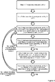
- Fig. 4 shows an example method for configuring the loudspeaker assembly 1 of Fig. 2 to obtain the operation shown in Fig. 3(b).
- Initial mounting angles of the loudspeakers L1, L2, L3, L4 may be chosen to provide a good starting point for obtaining cancellation of direct sound at each listening position, e.g. as shown in Fig. 2 .
- the loudspeakers L1, L2, L3, L4 preferably have a directivity index (according to the above definition) that is at least 6dB at a frequency of 3kHz, preferably so that loudspeaker L4 can be deemed to have an insignificant effect at listening position P1 and so that loudspeaker L1 can be deemed to have an insignificant effect at listening position P3 (as described below).
- Step 3 the direct sound produced by loudspeakers L2 and L3 at listening position P1 is measured, and a respective filter F2, F3 is defined for each of loudspeakers L2 and L3 so that the phase and amplitude of the direct sound produced by loudspeaker L1 and filtered loudspeakers L2, L3 at listening position P1 is cancelled in accordance with a predetermined cancelling condition (that requires the sound pressure level of direct sound produced by loudspeakers L1, L2, L3 at listening position P1 over 200 kHz-3kHz to be at least 12dB lower than the sound pressure level of direct sound produced by loudspeaker L1 at listening position P1).
- a predetermined cancelling condition that requires the sound pressure level of direct sound produced by loudspeakers L1, L2, L3 at listening position P1 over 200 kHz-3kHz to be at least 12dB lower than the sound pressure level of direct sound produced by loudspeaker L1 at listening position P1).
- Step 5 the direct sound produced by filtered loudspeakers L2 and L3 at listening position P3 is measured, and a filter F4 is defined for loudspeaker L4 so that the phase and amplitude of the filtered direct sound produced by loudspeakers L2, L3, L4 at listening position P3 is cancelled in accordance with the predetermined cancelling condition (that requires the sound pressure level of direct sound produced by loudspeakers L2, L3, L4 at listening position P3 over 200 kHz-3kHz to be at least 12dB lower than the sound pressure level of direct sound produced by loudspeakers L2, L3 at listening position P3).
- the effect of loudspeaker L1 at listening position P3 is ignored, since the angle of its principal radiating axis and its directivity index mean that the effect of direct sound produced by loudspeaker L1 at listening position P3 is deemed to be insignificant.
- Step 6 the direct sound produced by loudspeaker L1 and the filtered direct sound produced by loudspeakers L2, L3, L4 at listening position P2 is measured to determine whether the direct sound produced by loudspeakers L1, L2, L3, L4 at listening position P2 is cancelled in accordance with the predetermined cancelling condition (that requires the sound pressure level of direct sound produced by loudspeaker L1-L4 at listening position P2 over 200 kHz-3kHz to be at least 12dB lower than the sound pressure level of direct sound produced by loudspeaker L1 at listening position P2).
- the predetermined cancelling condition that requires the sound pressure level of direct sound produced by loudspeaker L1-L4 at listening position P2 over 200 kHz-3kHz to be at least 12dB lower than the sound pressure level of direct sound produced by loudspeaker L1 at listening position P2).
- direct sound is preferably measured in anechoic conditions, to avoid the influence of reflections.
- the sound of loudspeaker L1 is cancelled by the direct sound produced by filtered loudspeakers L2, L3.
- the direct sound produced by filtered loudspeaker L4 at listening position P1 is adequately low, and doesn't contribute significantly to the observation at position P1.
- the directivity index of the loudspeakers, the mounting angle and the electrical filtering are chosen as described above, so that cancellation of direct sound occurs at P1.
- filter 1 is a filter configured to cancel direct sound from L1 at sound at P3 and "filter 2" is a filter configured to cancel sound at P2.
- the response curve of the direct sound produced by L1 at P1 when filter 1 is applied is the substantially same as the unfiltered ("straight") direct sound produced by L1 at P3
- the response curve of the direct sound produced by L1 at P1 when filter 2 is applied is the substantially same as the unfiltered direct sound produced by L1 at P2.
Landscapes
- Engineering & Computer Science (AREA)
- Physics & Mathematics (AREA)
- Acoustics & Sound (AREA)
- Signal Processing (AREA)
- Health & Medical Sciences (AREA)
- Otolaryngology (AREA)
- General Health & Medical Sciences (AREA)
- Multimedia (AREA)
- Circuit For Audible Band Transducer (AREA)
- Obtaining Desirable Characteristics In Audible-Bandwidth Transducers (AREA)
Description
- This invention relates to loudspeaker assemblies and associated methods.
- Loudspeaker assemblies are often used in applications such as in home cinema, consumer electronics and automotive. In such applications, it is advantageous to direct the sound from the loudspeaker assembly in a particular direction, for example towards a listening position where it is expected that a person listening to the sound from the loudspeaker assembly will be located.
- In such applications, it is advantageous to be able to project sound in a particular direction (in particular, to create sound of a high directivity), so that sound is not wasted by sending it to areas where it is not needed. Furthermore, in applications where the speaker assembly is are required to play music, TV audio or film audio, the sound to be projected to a listener may incorporate a large range of sound frequencies. Hence, it is necessary for a loudspeaker assembly to produce high directivity sound over a wide range of frequencies, such that the full range of frequencies can be directed to the listener.
- Commonly, loudspeaker assemblies used in applications such as home cinema, consumer electronics and automotive are small, for example due to space constraints and/or cost constraints. Loudspeaker assemblies of a small size often suffer in that they are less effective at generating low-frequency sounds, owing to the small size of the speaker driver. Hence, the requirement to create highly directive sound at the low end of the audio frequency range is increased for small speaker units.
- The directivity of a loudspeaker relates to the distribution of the acoustic output (sound) from that loudspeaker, and may be defined in terms of a directivity index (e.g. as defined below). Loudspeakers with a high directivity index project sound preferably in a given direction or directions, whilst loudspeakers with a low directivity index tend to project sound more isotropically (equally in all directions)
- In many situations that involve an enclosed space, for example in a room of a house or in a car, it is preferable for a loudspeaker to have a high directivity index, such that sound is projected towards a listening position where the sound is needed (for example to a driver of a car), rather than wasting energy by projecting the sound to positions where it is not needed.
- Traditional loudspeakers, such as cone speakers, have some directivity by virtue of the coned speaker diaphragm, and owing to the fact that they are often housed in a way that prevents sound from escaping from a back of the loudspeaker.
- The directivity of a loudspeaker assembly that includes an array of multiple loudspeakers can be greatly improved over that of a single speaker, by using a series of speakers in combination. In particular, by driving the array of loudspeakers with electrical signals that are filtered so that there are differences in gain and/or phase between the electrical signals, it is possible to achieve a speaker assembly output with a high directivity, for example which projects sound primarily in a given direction.
-
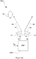
Fig. 1(a) shows a simple loudspeaker assembly referred to as acardioid loudspeaker assembly 1001, that includes an array of two loudspeakers L1, L2 each configured to produce sound S1, S2 along a respective principal radiation axis X1, X2. The loudspeakers L1, L2 are mounted with an angular offset between their principal radiation axes X1, X2. Each loudspeaker L1, L2 is configured to receive a respective electrical signal E1, E2 from acontrol unit 1020, which produces each of the electrical signals E1, E2 based on an input signal Ain representative of audio. The loudspeakers L1, L2 include a primary speaker L1 which receives an unfiltered electrical signal E1 and an auxiliary loudspeaker L2 that receives an electrical signal E2 that is filtered with respect to the electrical signal E1 received by the primary loudspeaker L1 such that there is a gain and phase difference between the electrical signals E1, E2 received by the loudspeakers L1, L2 (the signal processing to achieve the gain and phase difference may include e.g. a signal inverter, a delay and a gain). In particular, the auxiliary loudspeaker L2 is driven by an electrical signal E2 that is filtered with a defined gain and phase difference from the electrical signal E1 received by the primary loudspeaker L1 such that direct sound S1, S2 produced by the loudspeakers L1, L2 cancel each other at a listening position P1. -
Fig. 1(b) is a series of 2D polar plots showing the direct sound (sound pressure level) produced by thecardioid loudspeaker assembly 1001 ofFig. 1(a) at different frequencies. The sound has a polar pattern in the shape of a cardioid, with the direct sound produced by the cardioid loudspeaker assembly cancelling so as to form a "null" at the listening position P1. Note that the loudspeakers L1, L2 become more directive as frequency increases. - A typical application for a
cardioid loudspeaker assembly 1001 is a so called TV "sound bar" which attempt to create a listening perception that is far broader than the apparent physical width of the sound bar. The main principle is that the listener is located at the "null" of the cardioid formed by the direct sound S1, S2, so that little direct sound is heard at the listening position P1, but reflected (indirect) sound is instead heard at the listening position P1 after having been reflected from nearby walls. It is known that a reflection from a wall can act as a virtual sound source, so that a listener perceives sound from a virtual loudspeaker that is attached at the reflection point. Hence, acardioid loudspeaker assembly 1001, able to produce a high directivity acoustic output over a large space, is desirable to meet performance and cost requirements of a sound bar. Acardioid loudspeaker assembly 1001 could be referred to as a hyper directive system, since it typically uses loudspeakers that are highly directive. - The present inventors have observed that as the null of a
cardioid loudspeaker assembly 1001 is rather narrow, the "sweet spot" whereby sound is dominated by reflected sound rather than direct sound is rather restricted. The present inventors have also observed that the polarity of the acoustic waves produced by acardioid loudspeaker assembly 1001 changes when the listener turns around the cardioid. - It is known that directive loudspeaker arrays can be made by using a large number of loudspeaker units (typically 10 or more) mounted to have parallel principal radiating axes, with each loudspeaker being fed by an appropriate electrical signal, that is basically a delayed and/or filtered and gained replica of an input signal, see e.g. "Optimizing directivity properties of DSP controlled loudspeaker arrays", G.W.J. van Beuningen, E.W. Start, Presented at "Reproduced Sound 16 Conference", Stratford upon Avon (UK), 17 - 19 November 2000, Institute of Acoustics. However these systems have a high cost.
-
US 2013/279716A1 discloses a method of operating an audio system that provides audio radiation to a plurality of listening positions, which includes providing at least one source of audio signals. -
US 5870484A discloses a sound reproduction system in which both signals of a stereo pair of signals are radiated with a directional radiation pattern having a first order gradient characteristic over the frequency range where inter-aural time difference cues dominate localization in the human auditory system. -
US 5809150A discloses a system that generates skewed hypercardioid sound energy fields from right front and left front "surround" loudspeakers with the principal nulls directed at the expected listener location, which produces the effect of sidewall and rearwall loudspeakers in a home theatre setting without any actual sidewall or rearwall loudspeakers. -
EP2891338A1 andUS 2015/223002A1 disclose a system of rendering object-based audio content through a system that includes individually addressable drivers, including at least one driver that is configured to project sound waves toward one or more surfaces within a listening environment for reflection to a listening area within the listening environment; a renderer configured to receive and process audio streams and one or more metadata sets associated with each of the audio streams and specifying a playback location of a respective audio stream; and a playback system coupled to the renderer and configured to render the audio streams to a plurality of audio feeds corresponding to the array of audio drivers in accordance with the one or more metadata sets. - The present invention has been devised in light of the above considerations.
- A first aspect of the invention may provide a loudspeaker assembly according to
claim 1. - In this way, when the loudspeaker assembly is used in an enclosed space, any audience member(s) located at the first, second or third listening position, or to a lesser extent between such positions, will, due to the cancellation of direct sound produced by the loudspeakers at the first, second and third listening positions, receive an increased proportion of sound indirectly from reflections of the sound off walls at the periphery of the enclosed space. Such reflections can acts as virtual sound sources, thereby improving the listening experience of the audience member(s).
- For the avoidance of any doubt, the contribution of any loudspeakers deemed to have an insignificant effect at a listening position may be ignored when evaluating whether direct sound produced by multiple loudspeakers in the loudspeaker assembly is cancelled in accordance with a predetermined cancelling condition at that listening position (see e.g. the discussion of
Fig. 4 below, where the contribution of L4 is ignored at P1). - Direct sound produced by a loudspeaker in the loudspeaker assembly may be defined as sound produced by the loudspeaker that has not been reflected by an intervening surface. Direct sound can be measured, for example, in an anechoic chamber. Direct sound can also be measured, for example, in a normal (non-anechoic) environment by using a gated measurement in which reflected sound is excluded by measuring direct sound using an appropriately defined time window.
- The loudspeaker assembly may include one or more additional loudspeakers.
- A loudspeaker assembly that includes four loudspeakers may be particularly useful if the loudspeaker assembly is intended to provide stereophonic sound.
- The loudspeakers included in the loudspeaker assembly may be arranged with their principal radiating axes symmetrically arranged in relation to a plane of symmetry, which may be a vertical plane of symmetry when the loudspeaker assembly is in use. Again, this may be useful if the loudspeaker assembly is intended to provide stereophonic sound.
- A principal radiating axis of a loudspeaker may be defined as an axis along which the loudspeaker produces direct sound at maximum amplitude (sound pressure level). A loudspeaker having a principle radiating axis may be referred to as a directional loudspeaker.
- The extent to which a loudspeaker is directional may be defined by a directivity index. For the purposes of this disclosure, the directivity index (DI) of a loudspeaker at a given frequency (f) may be defined in dB as:

H (f) is an average "off axis" sound pressure level as measured off the principal radiating axis. The "on axis" and "off axis" sound pressure levels may be measured at a standard distance from the loudspeaker, e.g. 1 metre. - By nature, DI tends to increase with frequency, since loudspeakers tend to be more directive at higher frequencies (as can be seen from some of the figures discussed below).
- In general, it is not possible/practical to measure H(f) for all directions, so
H (f) is usually approximated in practice according to a defined technique. - There are many techniques that can be used to approximate
H(f) , see e.g. "On the Calculation of Full and Partial Directivity Indices", Technical Report, Tylka, 16 November 2014 3D Audio and Applied Acoustics Laboratory, Princeton University. - For the purposes of this disclosure,
H(f) may be approximated using the average of four "off axis" measurements taken within a plane at angles of 15°, 30°, 45°, and 60° relative to a principal radiating axis of the loudspeaker. If a diaphragm of the loudspeaker has a non-constant radius (e.g. because the diaphragm has an elliptical/oval form), the plane in which the measurements are taken may be a plane in which a maximum radius of the diaphragm lies. - Preferably, each loudspeaker in the loudspeaker assembly has a directivity index (according to the above definition) that is at least 6dB at a frequency of 3kHz. This provides a loudspeaker with a relatively high directivity compared to loudspeakers typically used in a "soundbar", which the present inventors have found useful for achieving adequate cancellation of direct audio signals produced by the loudspeaker assembly at multiple listening positions.
- For avoidance of any doubt, a gain and phase difference between two electric signals may include a difference in gain and/or a difference in phase between the two electric signals.
- Preferably, each gain and phase difference is frequency dependent. For example, each gain and phase difference may be zero below a threshold frequency value, and non-zero above the threshold frequency value. This has been found to improve listener perception, since because directivity is less important at lower frequencies. The threshold frequency value may be 150Hz.
- As would be appreciated by a skilled person, perfect cancellation of direct sound produced by multiple loudspeakers at a given listening position may be very difficult, if not impossible, to achieve in practice.
- Accordingly, a predetermined cancelling condition at a given listening position may be defined in such a way that does not require perfect cancellation of sound at that listening position, but might instead require cancellation that is acceptable.
- Preferably, the predetermined cancelling condition at each listening position requires that, over a predetermined frequency range (which predetermined frequency range may be 200Hz-3kHz), the sound pressure level of direct sound produced by the loudspeakers in the loudspeaker assembly at the listening position is at least X dB lower than the sound pressure level of direct sound produced by a subset of the loudspeakers in the loudspeaker assembly at the listening position. X is preferably 12 dB, but may be a larger value (e.g. 15 dB). This measurement does not require a special input signal representative signal to be used. Any input signal having a frequency range of 200Hz-3kHz could be used for such measurements, such as a full band input signal traditionally used for loudspeaker measurements.
- Techniques for measuring direct sound produced at a listening position by one or more loudspeakers are well known, but could, for example, involve supplying a test input signal (e.g. representative of audio having frequencies covering a frequency range of interest, e.g. the predetermined frequency range referred to above) to the one or more loudspeakers, and measuring the direct sound received at that listening position. As noted above, direct sound received at a listening position can be measured, for example, in an anechoic environment. Direct sound can also be measured, for example, in a normal (non-anechoic) environment by using a gated measurement in which reflected sound is excluded by measuring direct sound using an appropriately defined time window.
- For avoidance of any doubt, measurements of direct sound do not require a special input signal representative signal to be used. Any input signal having a frequency range of interest could be used for such measurements, such as a full band input signal traditionally used for loudspeaker measurements.
- Preferably, there is an angular offset between the principal axes of each pair of loudspeakers in the loudspeaker assembly that is at least a predetermined threshold angle. The predetermined threshold angle is preferably 15° or more, 30° or more, more preferably 45° or more, more preferably 60° or more. Having such a predetermined threshold angle has been found to permit adequate cancellation of direct sound produced by loudspeakers in the loudspeaker assembly at multiple listening positions.
- In this context, each pair of loudspeakers in the loudspeaker assembly may be taken to mean each possible pair of loudspeakers in the loudspeaker assembly.
- Preferably, the loudspeakers in the loudspeaker assembly are arranged so that between each pair of loudspeakers in the loudspeaker assembly there is a distance that is no more than a predetermined threshold distance. Preferably, the predetermined threshold distance is at least twice as large as a distance between one of the loudspeakers in the loudspeaker assembly and one of the listening positions. Having such a predetermined threshold distance is useful for achieving adequate cancellation of direct audio signals produced by the loudspeaker assembly at multiple listening positions.
- Preferably, the predetermined threshold distance is 50 cm or less, more preferably 40 cm or less. This might be useful for a typical soundbar, for example.
- A listening position may be defined relative to the loudspeaker assembly, and may represent a position where it is expected that a person listening to sound from the loudspeaker assembly will be located when the loudspeaker assembly is in use.
- For avoidance of any doubt, whilst the loudspeakers in the loudspeaker assembly may be mounted with their principal axes in the same plane, this is not a requirement of the invention, since other arrangements may be appropriate depending on the intended application of the loudspeaker assembly (e.g. if the loudspeaker assembly is intended for use in a car).
- The loudspeaker assembly enclosure may have a bar shape, e.g. such that the loudspeaker assembly provides a "soundbar".
- Each loudspeaker may be an electro-dynamic loudspeaker.
- Each loudspeaker may include:
- a permanent magnet assembly (e.g. comprising metal components and a permanent magnet);
- a voice coil assembly (e.g. comprising a wire referred to as a voice coil wound/wrapped around a thin tube referred to as a voice coil former);
- a diaphragm;
- a chassis;
- a suspension system which suspends the diaphragm from the chassis (e.g. including an edge suspension and a spider).
- The voice coil is preferably configured to interact with a static magnetic field of the permanent magnet when an electric current is passed through the voice coil. An interaction between the voice coil and the static magnetic field of the permanent magnet preferably results in movement of the voice coil along a predetermined axis.
- Preferably, each loudspeaker in the loudspeaker assembly is mounted within its own individual loudspeaker enclosure, preferably so that back radiation from each loudspeaker does not have a significant influence on other loudspeakers in the loudspeaker assembly.
- Each loudspeaker may have a diaphragm that has a circular or an elliptical form.
- The loudspeaker assembly enclosure may be a vented box, or a closed box.
- The control unit may include a digital signal processor ("DSP"), for example.
- A second aspect of the invention may provide a method of configuring a loudspeaker assembly according to claim 10.
- Adjusting an angular offset between the principal radiating axes of two loudspeakers may include changing a mounting angle of either/both of those loudspeakers in the loudspeaker assembly. The angular offsets may be adjusted from initial angular offsets corresponding to initial mounting angles of the loudspeakers in the loudspeaker assembly, wherein the initial mounting angles were chosen to provide a good starting point for obtaining cancellation of direct sound at each listening position.
- Adjusting a phase and gain difference between electrical signals received by two loudspeakers may include defining a new filter/adjusting an existing filter for either/both of (the electrical signal(s) received by) those loudspeakers in the loudspeaker assembly.
- The method may include any method step implementing or corresponding to any apparatus feature described in connection with any above aspect of the invention.
- The method is preferably iterative, and may include measuring direct sound at each listening position, e.g. in an anechoic environment.
- The invention is defined in the appended independent claims. The dependent claims thereof define preferred embodiments of the invention.
- Examples of these proposals are discussed below, with reference to the accompanying drawings in which:
-
Fig. 1(a) shows an example cardioid loudspeaker assembly useful for understanding the present invention. -
Fig. 1(b) is a series of 2D polar plots showing the direct sound (sound pressure level) produced by thecardioid loudspeaker assembly 1001 ofFig. 1(a) at different frequencies, along with the polarity of each lobe. -
Fig. 2 shows a loudspeaker assembly according to the present invention. -
Fig. 3 compares the operation of (a) the cardioid loudspeaker assembly ofFig. 1(a) with (b) the operation of the loudspeaker assembly ofFig. 2 . -
Fig. 4 shows an example method of configuring the loudspeaker assembly ofFig. 2 . -
Fig. 5 is a schematic diagram that provides a simplified visualisation of the cancellation that occurs at listening positions P1-P3 when filtering derived according to the method ofFig. 4 is applied to electrical signals E1-E4 received by loudspeakers L1-L4 from the loudspeaker assembly ofFig. 2 . -
Fig. 6 illustrates the similarity in effect on the sound pressure level of direct sound produced by a loudspeaker at a listening position caused by either (i) increasing the angle between the principal radiating axis of the loudspeaker relative to the position of the loudspeaker; or (ii) filtering the electrical signal received by the loudspeaker to cancel the direct sound produced by another loudspeaker in the same loudspeaker array. - In general, the following discussion describes examples of our proposals that provide a loudspeaker assembly enclosure including four loudspeakers at predefined angles, where every loudspeaker unit receives an appropriate signal. A preferred aim is to obtain a given directional sound radiating.
- In general terms, the present examples may be viewed as building on the concept of the
cardioid loudspeaker assembly 1001 described with reference toFig. 1(a) . - In an example discussed below, four speakers mounted in an enclosure have a geometry (mounting angles) that is dictated by the directivity of each loudspeaker.
- In an example, four loudspeakers are mounted in a loudspeaker assembly enclosure in such a way that sound produced by each loudspeaker is radiating out from the enclosure in a controlled manner in the horizontal plane. In these examples, sound may radiate out from the enclosure in an arbitrary manner in the vertical plane - if control in this vertical plane were wanted, then this may be achieved by mounting additional loudspeakers in the vertical plane, e.g. with a second and third row (and possibly additional rows) of loudspeakers.
- In some examples, the specific signal processing for each loudspeaker may be tuned or adapted, dictated by the directivity of each loudspeaker unit, by the mounting angle of the loudspeakers, and by the desired polar pattern of the complete enclosure.
- In some examples, the loudspeakers may be mounted also with a certain angle relative to a z-direction where the z direction is defined as being an axis orthogonal to the upper plane of the enclosure.
- In some examples, the signal processing for each loudspeaker may be a delay, a gain, and a filter, whose parameters have to be defined in function of the target directivity, directivity of the individual loudspeaker units and the mounting angles.
- In some examples, the directivity of the loudspeaker assembly may change in function of frequency, e.g. for low frequencies (e.g. below 150Hz), all loudspeaker units may have the same driving signal, so that low frequencies are reproduced by all loudspeakers in the loudspeaker assembly.
-
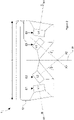
Fig. 2 shows aloudspeaker assembly 1 that includes four loudspeakers L1, L2, L3, L4 mounted within a singleloudspeaker assembly enclosure 12. For reasons discussed below, the loudspeaker may be referred to as providing a "hyper directional loudspeaker enclosure". - The loudspeakers L1, L2, L3, L4 are arranged in a linear array, with each loudspeaker L1, L2, L3, L4 preferably being mounted within its own individual loudspeaker enclosure so that back radiation from each loudspeaker L1, L2, L3, L4 does not have a significant influence on other loudspeakers in the
loudspeaker assembly 1. - As shown in
Fig. 2 , each loudspeaker L1, L2, L3, L4 has a respective principal radiating axis X1, X2, X3, X4 along which it produces sound. - As is also shown in
Fig. 2 , there is a first angular offset between the first and second principal radiating axes X1, X2, a second angular offset between the first and third principal radiating axes X1, X3, and a third angular offset between the first and fourth principal radiating axes X1, X4. - It can be seen from
Fig. 2 that there is an angular offset between the principal axes of each pair of loudspeaker in the loudspeaker assembly that is at least 30° - The distance between L1 and L4 is preferably no more than 50 cm.
- Each loudspeaker L1, L2, L3, L4 is configured to receive a respective electrical signal E1, E2, E3, E4 from a control unit (not shown), based on an input signal representative of audio (not shown). The control unit may be a DSP, for example.
- In this example, a first electrical signal E1 received by the first loudspeaker L1 is unfiltered, but the control unit is configured to filter second, third and fourth electrical signals E2, E3, E4 received (respectively) by the second, third and fourth loudspeakers L2, L3, L4 such that there is a first gain and phase difference between the first and second electrical signals E1, E2, a second gain and phase difference between the first and third electrical signals E1, E3, and a third gain and phase difference between the first and fourth electrical signals E1, E4.
-
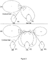
Fig. 3 compares the operation of (a) thecardioid loudspeaker assembly 1001 ofFig. 1(a) with (b) the operation of theloudspeaker assembly 1 ofFig. 2 . - As shown in Fig. 3(a), whilst direct sound produced by the loudspeakers in a cardioid loudspeaker assembly may cancel at a first listening position P1, the direct sound will in general not cancel in an adjacent listening position P2, at least not across a wide range of frequencies. Thus, only a listener positioned at the first listening position P1 will perceive sound produced by the cardioid loudspeaker assembly in a mainly reflective (indirect) way.
- In contrast, Fig. 3(b) shows the
loudspeaker assembly 1 ofFig. 2 which is preferably configured, e.g. according to the method described below, so that direct sound produced by the loudspeakers in the loudspeaker assembly cancel at first, second and third listening positions P1, P2, P3. Thus, a listener positioned at any of the first, second or third listening positions P1, P2, P3, or indeed between such positions, will perceive sound produced by theloudspeaker assembly 1 in a mainly reflective (indirect) way. -
Fig. 4 shows an example method for configuring theloudspeaker assembly 1 ofFig. 2 to obtain the operation shown in Fig. 3(b). - Initial mounting angles of the loudspeakers L1, L2, L3, L4 may be chosen to provide a good starting point for obtaining cancellation of direct sound at each listening position, e.g. as shown in
Fig. 2 . The loudspeakers L1, L2, L3, L4 preferably have a directivity index (according to the above definition) that is at least 6dB at a frequency of 3kHz, preferably so that loudspeaker L4 can be deemed to have an insignificant effect at listening position P1 and so that loudspeaker L1 can be deemed to have an insignificant effect at listening position P3 (as described below). - In
Step 1, a mounting angle is chosen for loudspeaker L1. Loudspeaker L4 may be mounted to have its principal radiating axis X4 symmetrically arranged in relation to the principal radiating axis X1 in relation to a plane of symmetry W, if stereophonic sound is wanted. - In
Step 2, the direct sound produced by loudspeaker L1 at listening position P1 is measured. - In
Step 3, the direct sound produced by loudspeakers L2 and L3 at listening position P1 is measured, and a respective filter F2, F3 is defined for each of loudspeakers L2 and L3 so that the phase and amplitude of the direct sound produced by loudspeaker L1 and filtered loudspeakers L2, L3 at listening position P1 is cancelled in accordance with a predetermined cancelling condition (that requires the sound pressure level of direct sound produced by loudspeakers L1, L2, L3 at listening position P1 over 200 kHz-3kHz to be at least 12dB lower than the sound pressure level of direct sound produced by loudspeaker L1 at listening position P1). The effect of loudspeaker L4 at listening position P1 is ignored, since the angle of its principal radiating axis X4, its directivity index, and the subsequent filtering of this loudspeaker (see Step 5) mean that the effect of direct sound produced by loudspeaker L4 at listening position P1 is deemed to be insignificant. - In
Step 4, the direct sound produced by loudspeaker L1 and the direct sound produced by filtered loudspeakers L2 and L3 is measured at listening position P2 to determine whether the direct sound produced by loudspeakers L1, L2, L3 at listening position P2 is cancelled in accordance with the predetermined cancelling condition (that requires the sound pressure level of direct sound produced by loudspeaker L1, L2, L3 at listening position P2 over 200 kHz-3kHz to be at least 12dB lower than the sound pressure level of direct sound produced by loudspeaker L1 at listening position P2). - If yes, the method proceeds to
Step 5. - If no, then the mounting angle of loudspeakers L2 and L3 is adjusted (preferably with these loudspeakers having principal radiating axes that are symmetrical in relation to the plane of symmetry W) and the method returns to Step 3 until at
Step 4 the direct sound produced by loudspeaker L1 and filtered loudspeakers L2 and L3 at listening position P2 is cancelled in accordance with the predetermined cancelling condition. - In
Step 5, the direct sound produced by filtered loudspeakers L2 and L3 at listening position P3 is measured, and a filter F4 is defined for loudspeaker L4 so that the phase and amplitude of the filtered direct sound produced by loudspeakers L2, L3, L4 at listening position P3 is cancelled in accordance with the predetermined cancelling condition (that requires the sound pressure level of direct sound produced by loudspeakers L2, L3, L4 at listening position P3 over 200 kHz-3kHz to be at least 12dB lower than the sound pressure level of direct sound produced by loudspeakers L2, L3 at listening position P3). The effect of loudspeaker L1 at listening position P3 is ignored, since the angle of its principal radiating axis and its directivity index mean that the effect of direct sound produced by loudspeaker L1 at listening position P3 is deemed to be insignificant. - In
Step 6, the direct sound produced by loudspeaker L1 and the filtered direct sound produced by loudspeakers L2, L3, L4 at listening position P2 is measured to determine whether the direct sound produced by loudspeakers L1, L2, L3, L4 at listening position P2 is cancelled in accordance with the predetermined cancelling condition (that requires the sound pressure level of direct sound produced by loudspeaker L1-L4 at listening position P2 over 200 kHz-3kHz to be at least 12dB lower than the sound pressure level of direct sound produced by loudspeaker L1 at listening position P2). - In the above method, direct sound is preferably measured in anechoic conditions, to avoid the influence of reflections.
-
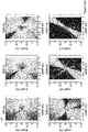
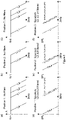
Fig. 5 is a schematic diagram that provides a simplified visualisation of the cancellation that occurs at listening positions P1-P3 when filtering derived according to the method ofFig. 4 is applied to electrical signals E1-E4 received by loudspeakers L1-L4 from the loudspeaker assembly ofFig. 2 . - Each chart in
Fig. 5 shows sound pressure level ("SPL") against frequency ("f"), with L1 being used as a reference (0dB). - Only amplitude is depicted in
Fig. 5 . The effect of phase differences caused by applying filters is to cause the cancellation shown by dotted lines inFig. 5(d)-(f) . - In
Fig. 5(a)-(c) , the sound pressure level at listening positions P1-P3 is shown when no filtering is applied to the electrical signals received by loudspeakers L1-L4. The different amplitude characteristics of the different loudspeakers shown in these figures is therefore caused solely by the mounting angle and directivity indices. - In
Fig. 5(d)-(f) , the sound pressure level at listening positions L1-L3 is shown when the filtering derived according to the method ofFig. 4 is applied to the electrical signals received by loudspeakers L1-L4 (note: according to the method ofFig. 4 , no filtering is applied to loudspeaker L1). For the purpose of this figure, direct sound produced by a filtered loudspeaker is represented as L+F (e.g. so direct sound produced by L2 is represented as L2+F2). - As described above, the filtering, directivity index and mounting angle of the loudspeakers L1-L4 is chosen so as to achieve cancelling of direct sound at listening positions P1-P3.
- Although there is some residual sound at listening positions P1-P3, the residual sound pressure level is adequately low, and the cancellation of direct sound at these positions has the effect of increasing the proportion of sound received at those positions indirectly from reflections of the audio signals off walls at the periphery of the enclosed space. Such reflections can acts as virtual sound sources, thereby improving the listening experience of audience member(s).
- In more detail, at listening position P1 (see
Figs. 5(a) and 5(d) ) the sound of loudspeaker L1 is cancelled by the direct sound produced by filtered loudspeakers L2, L3. The direct sound produced by filtered loudspeaker L4 at listening position P1 is adequately low, and doesn't contribute significantly to the observation at position P1. The directivity index of the loudspeakers, the mounting angle and the electrical filtering are chosen as described above, so that cancellation of direct sound occurs at P1. - At listening position P2 (see
Figs. 5(b) and 5(e) ), filtered loudspeaker L2 is producing more direct sound at listening position P2 than at listening position P1, while loudspeaker L3 is producing less direct sound at listening position P2 than at listening position P1. Careful choice of mounting angle and directivity of the speakers as described according to the iterative process described above has the effect of direct sound from filtered loudspeakers L2, L3 cancelling direct sound produced by loudspeaker L1 at listening position P2, whilst maintaining the cancelling of direct sound produced by loudspeaker L1 at listening position P1. Direct sound produced by filtered loudspeaker L4 is deemed adequately low to be ignored at listening positions P1 and P2 (although the direct sound produced by filtered loudspeaker L4 is later taken into account at listening position P2, seeStep 6 inFig. 4 ). - At listening position P3 (see
Figs. 5(c) and 5(e) ), direct sound produced by filtered loudspeaker L2 is dominant over direct sound produced by filtered loudspeaker L3 and is now cancelled by direct sound produced by filtered loudspeaker L4. This is possible by careful adjustment of filtering, mounting angle and directivity, as described previously. -
Fig. 6 illustrates the similarity in effect on the sound pressure level of direct sound produced by a loudspeaker at a listening position caused by either (i) increasing the angle between the principal radiating axis of the loudspeaker relative to the position of the loudspeaker; or (ii) filtering the electrical signal received by the loudspeaker to cancel the direct sound produced by another loudspeaker in the same loudspeaker array. - In
Fig. 6 , "filter 1" is a filter configured to cancel direct sound from L1 at sound at P3 and "filter 2" is a filter configured to cancel sound at P2. Hence, the response curve of the direct sound produced by L1 at P1 whenfilter 1 is applied is the substantially same as the unfiltered ("straight") direct sound produced by L1 at P3, and the response curve of the direct sound produced by L1 at P1 whenfilter 2 is applied is the substantially same as the unfiltered direct sound produced by L1 at P2. - This figure can help to explain the relationship between mounting angle and electrical filtering to create the desired radiation characteristics of each loudspeaker at the target positions, and also explains, for example, why the direct sound produced by loudspeaker L4 will have less of an effect at listening position P2 than the direct sound produced by loudspeaker L1.
- When used in this specification and claims, the terms "comprises" and "comprising", "including" and variations thereof mean that the specified features, steps or integers are included. The terms are not to be interpreted to exclude the possibility of other features, steps or integers being present.
Claims (11)
- A loudspeaker assembly (1) comprising:a first loudspeaker (L1) configured to receive a first electrical signal (E1), and to produce sound along a first principal radiating axis (X1) based on the first electrical signal;a second loudspeaker (L2) configured to receive a second electrical signal (E2), and to produce sound along a second principal radiating axis (X2) based on the second electrical signal;a third loudspeaker (L3) configured to receive a third electrical signal, and to produce sound along a third principal radiating axis (X3) based on the third electrical signal (E3);a fourth loudspeaker (L4) configured to receive a fourth electrical signal (E4), and to produce sound along a fourth principal radiating axis (X4) based on the fourth electrical signal; anda control unit configured to produce each of the first, second, third and fourth electrical signals based on an input signal representative of audio;wherein there is a first angular offset between the first and second principal radiating axes, a second angular offset between the first and third principal radiating axes, and a third angular offset between the first and fourth principal radiating axes (X1, X4);wherein the control unit is configured to filter at least two of the first, second and third electrical signals so that there is a first gain and phase difference between the first and second electrical signals and a second gain and phase difference between the first and third electrical signals, wherein the control unit is configured to filter the fourth electrical signal so that there is a third gain and phase difference between the first and fourth electrical signals (E1, E4);wherein the first, second and third angular offsets and the first, second and third gain and phase differences are configured so that, when the loudspeaker assembly is in use, direct sound produced by the loudspeakers in the loudspeaker assembly is cancelled in accordance with a predetermined cancelling condition at each of a first listening position (P1), a second listening position (P2) and a third listening position (P3);wherein the loudspeaker assembly is configured to be used in an enclosed space;wherein the loudspeakers in the loudspeaker assembly are mounted within a single loudspeaker assembly enclosure (12), with the first, second and third listening positions located outside the loudspeaker assembly enclosure (12);wherein the loudspeakers are arranged in a linear array;wherein the two loudspeakers on the ends of the linear array have principal radiation axes that point out from opposing side faces of the single loudspeaker assembly enclosure (12), wherein the two loudspeakers interior of the two loudspeakers on the ends of the linear array at least partially face towards each other and have principal radiation axes that point out of a front face of the single loudspeaker assembly enclosure, wherein the front face of the single loudspeaker assembly enclosure (12) faces the listening positions; andwherein the first, second and third listening positions are arranged in a linear array.
- A loudspeaker assembly according to claim 1, wherein each loudspeaker in the loudspeaker assembly has a directivity index that is at least 6dB at a frequency of 3kHz.
- A loudspeaker assembly according to claim 1 or 2, wherein each gain and phase difference is zero below 150Hz.
- A loudspeaker assembly according to any previous claim, wherein the predetermined cancelling condition at each listening position requires that, over a frequency range of 200Hz-3kHz, the sound pressure level of direct sound produced by all of the loudspeakers in the loudspeaker assembly at the listening position is at least 12 dB lower than the sound pressure level of direct sound produced by a subset of the loudspeakers in the loudspeaker assembly at the listening position.
- A loudspeaker assembly according to any previous claim, wherein:
the loudspeakers in the loudspeaker assembly are arranged so that between each pair of loudspeakers in the loudspeaker assembly there is a distance that is no more than 50 cm. - A loudspeaker assembly according to any previous claim, wherein there is an angular offset between the principle axes of each pair of loudspeakers in the loudspeaker assembly that is at least 30°.
- A loudspeaker assembly according to any previous claim, wherein the loudspeaker assembly enclosure has a bar shape and is configured as a soundbar.
- A loudspeaker assembly according to any previous claim, wherein each loudspeaker is an electro-dynamic loudspeaker that includes:a permanent magnet assembly comprising metal components and a permanent magnet;a voice coil assembly comprising a wire referred to as a voice coil wound/wrapped around a thin tube referred to as a voice coil former;a diaphragm;a chassis;a suspension system which suspends the diaphragm from the chassis;wherein the voice coil is configured to interact with a static magnetic field of the permanent magnet when an electric current is passed through the voice coil such that an interaction between the voice coil and the static magnetic field of the permanent magnet results in movement of the voice coil along a predetermined axis.
- A loudspeaker assembly according to any previous claim, wherein each loudspeaker in the loudspeaker assembly is mounted within its own individual loudspeaker enclosure so that back radiation from each loudspeaker does not have a significant influence on other loudspeakers in the loudspeaker assembly.
- A method of configuring a loudspeaker assembly, the loudspeaker assembly comprising:a first loudspeaker (L1) configured to receive a first electrical signal (E1), and to produce sound along a first principal radiating axis (X1) based on the first electrical signal;a second loudspeaker (L2) configured to receive a second electrical signal (E2), and to produce sound along a second principal radiating axis (X2) based on the second electrical signal;a third loudspeaker (L3) configured to receive a third electrical signal (E3), and to produce sound along a third principal radiating axis (X3) based on the third electrical signal;a fourth loudspeaker (L4) configured to receive a fourth electrical signal (E4), and to produce sound along a fourth principal radiating axis (X4) based on the fourth electrical signal (E4); anda control unit configured to produce each of the first, second and third electrical signals based on an input signal representative of audio;wherein there is a first angular offset between the first and second principal radiating axes, a second angular offset between the first and third principal radiating axes and a third angular offset between the first and fourth principal radiating axes (X1, X4);wherein the control unit is configured to filter at least two of the first, second and third electrical signals so that there is a first gain and phase difference between the first and second electrical signals and a second gain and phase difference between the first and third electrical signals, wherein the control unit is configured to filter the fourth electrical signal so that there is a third gain and phase difference between the first and fourth electrical signals (E1, E4);wherein the loudspeaker assembly is configured to be used in an enclosed space;wherein the method includes adjusting the first, second and third angular offsets and the first, second and third gain and phase differences so that, when the loudspeaker assembly is in use, direct sound produced by the loudspeakers in the loudspeaker assembly is cancelled in accordance with a predetermined cancelling condition at each of a first listening position (P1), a second listening position (P2) and a third listening position (P3);wherein the loudspeakers in the loudspeaker assembly are mounted within a single loudspeaker assembly enclosure (12), with the first, second and third listening positions located outside the loudspeaker assembly enclosure (12);wherein the loudspeakers are arranged in a linear array;wherein the two loudspeakers on the ends of the linear array have principal radiation axes that point out from opposing side faces of the single loudspeaker assembly enclosure (12), wherein the two loudspeakers interior of the two loudspeakers on the ends of the linear array at least partially face towards each other and have principal radiation axes that point out of a front face of the single loudspeaker assembly enclosure, wherein the front face of the single loudspeaker assembly enclosure (12) faces the listening positions; andwherein the first, second and third listening positions are arranged in a linear array.
- A method according to claim 10, wherein configuring the loudspeaker assembly also includes:(i) at a first one of the listening positions, measuring direct sound produced by a first subset of the loudspeakers in the loudspeaker assembly and, based on the measured direct sound, adjusting one or more of the gain and phase differences so that direct sound produced by multiple loudspeakers in the loudspeaker assembly is cancelled in accordance with a predetermined cancelling condition at the first listening position;(ii) at a second one of the listening positions, measuring direct sound produced by multiple loudspeakers in the loudspeaker assembly and evaluating whether the direct sound produced by the multiple loudspeakers is cancelled in accordance with the predetermined cancelling condition at the second listening position;(iii) if the direct sound produced by the multiple loudspeakers is not cancelled in accordance with the predetermined cancelling condition at the second listening position, adjusting one or more of the angular offsets and returning to step (i);(iv) at a third one of the listening positions, measuring direct sound produced by a second subset of the loudspeakers in the loudspeaker assembly and, based on the measured direct sound, adjusting the third gain and phase difference so that direct sound produced by multiple loudspeakers in the loudspeaker assembly is cancelled in accordance with a predetermined cancelling condition at the third listening position;(v) at the second listening position, measuring direct sound produced by multiple loudspeakers in the loudspeaker assembly and evaluating whether the direct sound produced by the multiple loudspeakers is cancelled in accordance with the predetermined cancelling condition at the second listening position;(vi) if the direct sound produced by the multiple loudspeakers is not cancelled in accordance with the predetermined cancelling condition at the second listening position, adjusting one or more of the angular offsets and returning to step (i).
Applications Claiming Priority (2)
| Application Number | Priority Date | Filing Date | Title |
|---|---|---|---|
| GB1522136.9A GB2545439A (en) | 2015-12-15 | 2015-12-15 | Loudspeaker assemblies and associated methods |
| PCT/EP2016/078631 WO2017102278A1 (en) | 2015-12-15 | 2016-11-24 | Loudspeaker assemblies and associated methods |
Publications (2)
| Publication Number | Publication Date |
|---|---|
| EP3391663A1 EP3391663A1 (en) | 2018-10-24 |
| EP3391663B1 true EP3391663B1 (en) | 2022-11-02 |
Family
ID=55274803
Family Applications (1)
| Application Number | Title | Priority Date | Filing Date |
|---|---|---|---|
| EP16800982.7A Active EP3391663B1 (en) | 2015-12-15 | 2016-11-24 | Loudspeaker assemblies and associated methods |
Country Status (5)
| Country | Link |
|---|---|
| US (1) | US10880648B2 (en) |
| EP (1) | EP3391663B1 (en) |
| CN (1) | CN108476359B (en) |
| GB (1) | GB2545439A (en) |
| WO (1) | WO2017102278A1 (en) |
Families Citing this family (8)
| Publication number | Priority date | Publication date | Assignee | Title |
|---|---|---|---|---|
| WO2020181288A1 (en) * | 2019-03-07 | 2020-09-10 | Polk Audio, Llc | Active cancellation of a height-channel soundbar array's forward sound radiation |
| US20210274282A1 (en) * | 2019-06-17 | 2021-09-02 | Audio Accessories Group, LLC | Sound bar with various couplings |
| US11463811B2 (en) * | 2020-04-10 | 2022-10-04 | Harman International Industries, Incorporated | Speaker system with overhead sound projection |
| CN111787478A (en) * | 2020-06-23 | 2020-10-16 | 北京小米移动软件有限公司 | Device control method and device |
| GB2600538B (en) * | 2020-09-09 | 2023-04-05 | Tymphany Worldwide Enterprises Ltd | Method of providing audio in a vehicle, and an audio apparatus for a vehicle |
| DE102021203632A1 (en) | 2021-04-13 | 2022-10-13 | Kaetel Systems Gmbh | Loudspeaker, signal processor, method for manufacturing the loudspeaker or method for operating the signal processor using dual-mode signal generation with two sound generators |
| GB2627479A (en) | 2023-02-23 | 2024-08-28 | Meridian Audio Ltd | Generating audio driving signals for the production of simultaneous stereo sound stages |
| US20250274711A1 (en) * | 2024-02-28 | 2025-08-28 | Gilberto Torres Ayala | Collider system for the generation and reproduction of signals from trisonic audio with zero latency |
Citations (2)
| Publication number | Priority date | Publication date | Assignee | Title |
|---|---|---|---|---|
| US5809150A (en) * | 1995-06-28 | 1998-09-15 | Eberbach; Steven J. | Surround sound loudspeaker system |
| EP2891338A1 (en) * | 2012-08-31 | 2015-07-08 | Dolby Laboratories Licensing Corporation | System for rendering and playback of object based audio in various listening environments |
Family Cites Families (14)
| Publication number | Priority date | Publication date | Assignee | Title |
|---|---|---|---|---|
| US5870484A (en) | 1995-09-05 | 1999-02-09 | Greenberger; Hal | Loudspeaker array with signal dependent radiation pattern |
| US5809153A (en) * | 1996-12-04 | 1998-09-15 | Bose Corporation | Electroacoustical transducing |
| JP3422281B2 (en) * | 1999-04-08 | 2003-06-30 | ヤマハ株式会社 | Directional loudspeaker |
| US20040109570A1 (en) * | 2002-06-21 | 2004-06-10 | Sunil Bharitkar | System and method for selective signal cancellation for multiple-listener audio applications |
| ITBS20050006A1 (en) * | 2005-01-28 | 2006-07-29 | Outline Di Noselli G & C S N C | DIFFUSING ELEMENT OF THE SOUND TO FORM VERTICAL LINE SPEAKER SYSTEMS WITH ADJUSTABLE DIRECTIVITY BOTH HORIZONTALLY IS VERTICALLY |
| US9100748B2 (en) * | 2007-05-04 | 2015-08-04 | Bose Corporation | System and method for directionally radiating sound |
| US20080273722A1 (en) * | 2007-05-04 | 2008-11-06 | Aylward J Richard | Directionally radiating sound in a vehicle |
| CN201138867Y (en) * | 2008-01-09 | 2008-10-22 | 龚立风 | Active acoustics in linear array |
| JP5643657B2 (en) * | 2008-03-13 | 2014-12-17 | コーニンクレッカ フィリップス エヌ ヴェ | Speaker array and drive device configuration related to speaker array |
| JP4557054B2 (en) * | 2008-06-20 | 2010-10-06 | 株式会社デンソー | In-vehicle stereophonic device |
| GB0821999D0 (en) * | 2008-12-02 | 2009-01-07 | Pss Belgium Nv | Method and apparatus for improved directivity of an acoustic antenna |
| CN101588524A (en) * | 2009-07-08 | 2009-11-25 | 电子科技大学 | Directionally adjustable miniature audio frequency directional loudspeaker |
| CN202143200U (en) * | 2011-05-20 | 2012-02-08 | 广州励华声光科技有限公司 | Variable directive sound box |
| CN202310093U (en) * | 2011-09-27 | 2012-07-04 | 清华大学 | Jagged array type piezoelectric loudspeaker set |
-
2015
- 2015-12-15 GB GB1522136.9A patent/GB2545439A/en not_active Withdrawn
-
2016
- 2016-11-24 US US16/062,740 patent/US10880648B2/en active Active
- 2016-11-24 EP EP16800982.7A patent/EP3391663B1/en active Active
- 2016-11-24 CN CN201680074754.9A patent/CN108476359B/en active Active
- 2016-11-24 WO PCT/EP2016/078631 patent/WO2017102278A1/en not_active Ceased
Patent Citations (3)
| Publication number | Priority date | Publication date | Assignee | Title |
|---|---|---|---|---|
| US5809150A (en) * | 1995-06-28 | 1998-09-15 | Eberbach; Steven J. | Surround sound loudspeaker system |
| EP2891338A1 (en) * | 2012-08-31 | 2015-07-08 | Dolby Laboratories Licensing Corporation | System for rendering and playback of object based audio in various listening environments |
| US20150223002A1 (en) * | 2012-08-31 | 2015-08-06 | Dolby Laboratories Licensing Corporation | System for Rendering and Playback of Object Based Audio in Various Listening Environments |
Also Published As
| Publication number | Publication date |
|---|---|
| US20200169808A1 (en) | 2020-05-28 |
| EP3391663A1 (en) | 2018-10-24 |
| US10880648B2 (en) | 2020-12-29 |
| GB201522136D0 (en) | 2016-01-27 |
| WO2017102278A1 (en) | 2017-06-22 |
| GB2545439A (en) | 2017-06-21 |
| CN108476359B (en) | 2022-02-15 |
| CN108476359A (en) | 2018-08-31 |
Similar Documents
| Publication | Publication Date | Title |
|---|---|---|
| EP3391663B1 (en) | Loudspeaker assemblies and associated methods | |
| US10038963B2 (en) | Speaker device and audio signal processing method | |
| CN102804814B (en) | Multi-channel sound playback method and device | |
| US20120269368A1 (en) | Loudspeaker array system | |
| JP2005159518A (en) | Array speaker | |
| KR20160001712A (en) | Method, apparatus and computer-readable recording medium for rendering audio signal | |
| JP2018527808A (en) | Sound bar | |
| US10945090B1 (en) | Surround sound rendering based on room acoustics | |
| KR102353871B1 (en) | Variable Acoustic Loudspeaker | |
| KR20140007794A (en) | Array loudspeaker system | |
| CN107079217A (en) | Loudspeaker with narrow dispersion | |
| EP3089476A1 (en) | Sound system | |
| US9843864B2 (en) | Method for operating an arrangement of sound transducers according to the wave field synthesis principle | |
| US4847904A (en) | Ambient imaging loudspeaker system | |
| Lee et al. | HRTF measurement for accurate sound localization cues | |
| US10440495B2 (en) | Virtual localization of sound | |
| CN107333206B (en) | Integrated speaker and control method | |
| CN119318161A (en) | Directional sound generating equipment | |
| JP4625756B2 (en) | Loudspeaker array system | |
| EP3790287A1 (en) | Loudspeaker system with active directivity control | |
| JP7160312B2 (en) | sound system | |
| Sporer et al. | Wave Field Synthesis | |
| US9729992B1 (en) | Front loudspeaker directivity for surround sound systems | |
| Frank et al. | Simple technical prediction of phantom source widening | |
| RU2575883C2 (en) | Acoustic system and operation method thereof |
Legal Events
| Date | Code | Title | Description |
|---|---|---|---|
| STAA | Information on the status of an ep patent application or granted ep patent |
Free format text: STATUS: UNKNOWN |
|
| STAA | Information on the status of an ep patent application or granted ep patent |
Free format text: STATUS: THE INTERNATIONAL PUBLICATION HAS BEEN MADE |
|
| PUAI | Public reference made under article 153(3) epc to a published international application that has entered the european phase |
Free format text: ORIGINAL CODE: 0009012 |
|
| STAA | Information on the status of an ep patent application or granted ep patent |
Free format text: STATUS: REQUEST FOR EXAMINATION WAS MADE |
|
| 17P | Request for examination filed |
Effective date: 20180713 |
|
| AK | Designated contracting states |
Kind code of ref document: A1 Designated state(s): AL AT BE BG CH CY CZ DE DK EE ES FI FR GB GR HR HU IE IS IT LI LT LU LV MC MK MT NL NO PL PT RO RS SE SI SK SM TR |
|
| AX | Request for extension of the european patent |
Extension state: BA ME |
|
| DAV | Request for validation of the european patent (deleted) | ||
| DAX | Request for extension of the european patent (deleted) | ||
| STAA | Information on the status of an ep patent application or granted ep patent |
Free format text: STATUS: EXAMINATION IS IN PROGRESS |
|
| 17Q | First examination report despatched |
Effective date: 20200807 |
|
| GRAP | Despatch of communication of intention to grant a patent |
Free format text: ORIGINAL CODE: EPIDOSNIGR1 |
|
| STAA | Information on the status of an ep patent application or granted ep patent |
Free format text: STATUS: GRANT OF PATENT IS INTENDED |
|
| INTG | Intention to grant announced |
Effective date: 20220622 |
|
| GRAS | Grant fee paid |
Free format text: ORIGINAL CODE: EPIDOSNIGR3 |
|
| GRAA | (expected) grant |
Free format text: ORIGINAL CODE: 0009210 |
|
| STAA | Information on the status of an ep patent application or granted ep patent |
Free format text: STATUS: THE PATENT HAS BEEN GRANTED |
|
| AK | Designated contracting states |
Kind code of ref document: B1 Designated state(s): AL AT BE BG CH CY CZ DE DK EE ES FI FR GB GR HR HU IE IS IT LI LT LU LV MC MK MT NL NO PL PT RO RS SE SI SK SM TR |
|
| REG | Reference to a national code |
Ref country code: GB Ref legal event code: FG4D |
|
| REG | Reference to a national code |
Ref country code: CH Ref legal event code: EP Ref country code: AT Ref legal event code: REF Ref document number: 1529642 Country of ref document: AT Kind code of ref document: T Effective date: 20221115 |
|
| REG | Reference to a national code |
Ref country code: DE Ref legal event code: R096 Ref document number: 602016076084 Country of ref document: DE |
|
| REG | Reference to a national code |
Ref country code: IE Ref legal event code: FG4D |
|
| REG | Reference to a national code |
Ref country code: LT Ref legal event code: MG9D |
|
| REG | Reference to a national code |
Ref country code: NL Ref legal event code: MP Effective date: 20221102 |
|
| REG | Reference to a national code |
Ref country code: AT Ref legal event code: MK05 Ref document number: 1529642 Country of ref document: AT Kind code of ref document: T Effective date: 20221102 |
|
| PG25 | Lapsed in a contracting state [announced via postgrant information from national office to epo] |
Ref country code: SE Free format text: LAPSE BECAUSE OF FAILURE TO SUBMIT A TRANSLATION OF THE DESCRIPTION OR TO PAY THE FEE WITHIN THE PRESCRIBED TIME-LIMIT Effective date: 20221102 Ref country code: PT Free format text: LAPSE BECAUSE OF FAILURE TO SUBMIT A TRANSLATION OF THE DESCRIPTION OR TO PAY THE FEE WITHIN THE PRESCRIBED TIME-LIMIT Effective date: 20230302 Ref country code: NO Free format text: LAPSE BECAUSE OF FAILURE TO SUBMIT A TRANSLATION OF THE DESCRIPTION OR TO PAY THE FEE WITHIN THE PRESCRIBED TIME-LIMIT Effective date: 20230202 Ref country code: LT Free format text: LAPSE BECAUSE OF FAILURE TO SUBMIT A TRANSLATION OF THE DESCRIPTION OR TO PAY THE FEE WITHIN THE PRESCRIBED TIME-LIMIT Effective date: 20221102 Ref country code: FI Free format text: LAPSE BECAUSE OF FAILURE TO SUBMIT A TRANSLATION OF THE DESCRIPTION OR TO PAY THE FEE WITHIN THE PRESCRIBED TIME-LIMIT Effective date: 20221102 Ref country code: ES Free format text: LAPSE BECAUSE OF FAILURE TO SUBMIT A TRANSLATION OF THE DESCRIPTION OR TO PAY THE FEE WITHIN THE PRESCRIBED TIME-LIMIT Effective date: 20221102 Ref country code: AT Free format text: LAPSE BECAUSE OF FAILURE TO SUBMIT A TRANSLATION OF THE DESCRIPTION OR TO PAY THE FEE WITHIN THE PRESCRIBED TIME-LIMIT Effective date: 20221102 |
|
| PG25 | Lapsed in a contracting state [announced via postgrant information from national office to epo] |
Ref country code: RS Free format text: LAPSE BECAUSE OF FAILURE TO SUBMIT A TRANSLATION OF THE DESCRIPTION OR TO PAY THE FEE WITHIN THE PRESCRIBED TIME-LIMIT Effective date: 20221102 Ref country code: PL Free format text: LAPSE BECAUSE OF FAILURE TO SUBMIT A TRANSLATION OF THE DESCRIPTION OR TO PAY THE FEE WITHIN THE PRESCRIBED TIME-LIMIT Effective date: 20221102 Ref country code: LV Free format text: LAPSE BECAUSE OF FAILURE TO SUBMIT A TRANSLATION OF THE DESCRIPTION OR TO PAY THE FEE WITHIN THE PRESCRIBED TIME-LIMIT Effective date: 20221102 Ref country code: IS Free format text: LAPSE BECAUSE OF FAILURE TO SUBMIT A TRANSLATION OF THE DESCRIPTION OR TO PAY THE FEE WITHIN THE PRESCRIBED TIME-LIMIT Effective date: 20230302 Ref country code: HR Free format text: LAPSE BECAUSE OF FAILURE TO SUBMIT A TRANSLATION OF THE DESCRIPTION OR TO PAY THE FEE WITHIN THE PRESCRIBED TIME-LIMIT Effective date: 20221102 Ref country code: GR Free format text: LAPSE BECAUSE OF FAILURE TO SUBMIT A TRANSLATION OF THE DESCRIPTION OR TO PAY THE FEE WITHIN THE PRESCRIBED TIME-LIMIT Effective date: 20230203 |
|
| P01 | Opt-out of the competence of the unified patent court (upc) registered |
Effective date: 20230502 |
|
| PG25 | Lapsed in a contracting state [announced via postgrant information from national office to epo] |
Ref country code: NL Free format text: LAPSE BECAUSE OF FAILURE TO SUBMIT A TRANSLATION OF THE DESCRIPTION OR TO PAY THE FEE WITHIN THE PRESCRIBED TIME-LIMIT Effective date: 20221102 |
|
| REG | Reference to a national code |
Ref country code: CH Ref legal event code: PL |
|
| PG25 | Lapsed in a contracting state [announced via postgrant information from national office to epo] |
Ref country code: SM Free format text: LAPSE BECAUSE OF FAILURE TO SUBMIT A TRANSLATION OF THE DESCRIPTION OR TO PAY THE FEE WITHIN THE PRESCRIBED TIME-LIMIT Effective date: 20221102 Ref country code: RO Free format text: LAPSE BECAUSE OF FAILURE TO SUBMIT A TRANSLATION OF THE DESCRIPTION OR TO PAY THE FEE WITHIN THE PRESCRIBED TIME-LIMIT Effective date: 20221102 Ref country code: LI Free format text: LAPSE BECAUSE OF NON-PAYMENT OF DUE FEES Effective date: 20221130 Ref country code: EE Free format text: LAPSE BECAUSE OF FAILURE TO SUBMIT A TRANSLATION OF THE DESCRIPTION OR TO PAY THE FEE WITHIN THE PRESCRIBED TIME-LIMIT Effective date: 20221102 Ref country code: DK Free format text: LAPSE BECAUSE OF FAILURE TO SUBMIT A TRANSLATION OF THE DESCRIPTION OR TO PAY THE FEE WITHIN THE PRESCRIBED TIME-LIMIT Effective date: 20221102 Ref country code: CZ Free format text: LAPSE BECAUSE OF FAILURE TO SUBMIT A TRANSLATION OF THE DESCRIPTION OR TO PAY THE FEE WITHIN THE PRESCRIBED TIME-LIMIT Effective date: 20221102 Ref country code: CH Free format text: LAPSE BECAUSE OF NON-PAYMENT OF DUE FEES Effective date: 20221130 |
|
| REG | Reference to a national code |
Ref country code: DE Ref legal event code: R097 Ref document number: 602016076084 Country of ref document: DE |
|
| PG25 | Lapsed in a contracting state [announced via postgrant information from national office to epo] |
Ref country code: SK Free format text: LAPSE BECAUSE OF FAILURE TO SUBMIT A TRANSLATION OF THE DESCRIPTION OR TO PAY THE FEE WITHIN THE PRESCRIBED TIME-LIMIT Effective date: 20221102 Ref country code: LU Free format text: LAPSE BECAUSE OF NON-PAYMENT OF DUE FEES Effective date: 20221124 Ref country code: AL Free format text: LAPSE BECAUSE OF FAILURE TO SUBMIT A TRANSLATION OF THE DESCRIPTION OR TO PAY THE FEE WITHIN THE PRESCRIBED TIME-LIMIT Effective date: 20221102 |
|
| PLBE | No opposition filed within time limit |
Free format text: ORIGINAL CODE: 0009261 |
|
| STAA | Information on the status of an ep patent application or granted ep patent |
Free format text: STATUS: NO OPPOSITION FILED WITHIN TIME LIMIT |
|
| 26N | No opposition filed |
Effective date: 20230803 |
|
| PG25 | Lapsed in a contracting state [announced via postgrant information from national office to epo] |
Ref country code: IE Free format text: LAPSE BECAUSE OF NON-PAYMENT OF DUE FEES Effective date: 20221124 |
|
| PG25 | Lapsed in a contracting state [announced via postgrant information from national office to epo] |
Ref country code: SI Free format text: LAPSE BECAUSE OF FAILURE TO SUBMIT A TRANSLATION OF THE DESCRIPTION OR TO PAY THE FEE WITHIN THE PRESCRIBED TIME-LIMIT Effective date: 20221102 |
|
| PG25 | Lapsed in a contracting state [announced via postgrant information from national office to epo] |
Ref country code: HU Free format text: LAPSE BECAUSE OF FAILURE TO SUBMIT A TRANSLATION OF THE DESCRIPTION OR TO PAY THE FEE WITHIN THE PRESCRIBED TIME-LIMIT; INVALID AB INITIO Effective date: 20161124 |
|
| PG25 | Lapsed in a contracting state [announced via postgrant information from national office to epo] |
Ref country code: CY Free format text: LAPSE BECAUSE OF FAILURE TO SUBMIT A TRANSLATION OF THE DESCRIPTION OR TO PAY THE FEE WITHIN THE PRESCRIBED TIME-LIMIT Effective date: 20221102 |
|
| PG25 | Lapsed in a contracting state [announced via postgrant information from national office to epo] |
Ref country code: MK Free format text: LAPSE BECAUSE OF FAILURE TO SUBMIT A TRANSLATION OF THE DESCRIPTION OR TO PAY THE FEE WITHIN THE PRESCRIBED TIME-LIMIT Effective date: 20221102 Ref country code: IT Free format text: LAPSE BECAUSE OF FAILURE TO SUBMIT A TRANSLATION OF THE DESCRIPTION OR TO PAY THE FEE WITHIN THE PRESCRIBED TIME-LIMIT Effective date: 20221102 |
|
| PG25 | Lapsed in a contracting state [announced via postgrant information from national office to epo] |
Ref country code: MC Free format text: LAPSE BECAUSE OF FAILURE TO SUBMIT A TRANSLATION OF THE DESCRIPTION OR TO PAY THE FEE WITHIN THE PRESCRIBED TIME-LIMIT Effective date: 20221102 |
|
| PG25 | Lapsed in a contracting state [announced via postgrant information from national office to epo] |
Ref country code: TR Free format text: LAPSE BECAUSE OF FAILURE TO SUBMIT A TRANSLATION OF THE DESCRIPTION OR TO PAY THE FEE WITHIN THE PRESCRIBED TIME-LIMIT Effective date: 20221102 Ref country code: MC Free format text: LAPSE BECAUSE OF FAILURE TO SUBMIT A TRANSLATION OF THE DESCRIPTION OR TO PAY THE FEE WITHIN THE PRESCRIBED TIME-LIMIT Effective date: 20221102 |
|
| PG25 | Lapsed in a contracting state [announced via postgrant information from national office to epo] |
Ref country code: BG Free format text: LAPSE BECAUSE OF FAILURE TO SUBMIT A TRANSLATION OF THE DESCRIPTION OR TO PAY THE FEE WITHIN THE PRESCRIBED TIME-LIMIT Effective date: 20221102 |
|
| PG25 | Lapsed in a contracting state [announced via postgrant information from national office to epo] |
Ref country code: MT Free format text: LAPSE BECAUSE OF FAILURE TO SUBMIT A TRANSLATION OF THE DESCRIPTION OR TO PAY THE FEE WITHIN THE PRESCRIBED TIME-LIMIT Effective date: 20221102 |
|
| PGFP | Annual fee paid to national office [announced via postgrant information from national office to epo] |
Ref country code: DE Payment date: 20241125 Year of fee payment: 9 |
|
| PGFP | Annual fee paid to national office [announced via postgrant information from national office to epo] |
Ref country code: BE Payment date: 20241202 Year of fee payment: 9 |
|
| PGFP | Annual fee paid to national office [announced via postgrant information from national office to epo] |
Ref country code: FR Payment date: 20241121 Year of fee payment: 9 |
|
| PGFP | Annual fee paid to national office [announced via postgrant information from national office to epo] |
Ref country code: GB Payment date: 20251119 Year of fee payment: 10 |