EP3391511B1 - Läufer für eine permanentmagneterregte synchronmaschine, pollückenstab für einen solchen läufer und verfahren zum herstellen eines solchen läufers - Google Patents
Läufer für eine permanentmagneterregte synchronmaschine, pollückenstab für einen solchen läufer und verfahren zum herstellen eines solchen läufers Download PDFInfo
- Publication number
- EP3391511B1 EP3391511B1 EP16795296.9A EP16795296A EP3391511B1 EP 3391511 B1 EP3391511 B1 EP 3391511B1 EP 16795296 A EP16795296 A EP 16795296A EP 3391511 B1 EP3391511 B1 EP 3391511B1
- Authority
- EP
- European Patent Office
- Prior art keywords
- rotor
- magnets
- pole gap
- pole
- rods
- Prior art date
- Legal status (The legal status is an assumption and is not a legal conclusion. Google has not performed a legal analysis and makes no representation as to the accuracy of the status listed.)
- Active
Links
Images

Classifications
-
- H—ELECTRICITY
- H02—GENERATION; CONVERSION OR DISTRIBUTION OF ELECTRIC POWER
- H02K—DYNAMO-ELECTRIC MACHINES
- H02K1/00—Details of the magnetic circuit
- H02K1/06—Details of the magnetic circuit characterised by the shape, form or construction
- H02K1/22—Rotating parts of the magnetic circuit
- H02K1/27—Rotor cores with permanent magnets
- H02K1/2706—Inner rotors
- H02K1/272—Inner rotors the magnetisation axis of the magnets being perpendicular to the rotor axis
- H02K1/274—Inner rotors the magnetisation axis of the magnets being perpendicular to the rotor axis the rotor consisting of two or more circumferentially positioned magnets
- H02K1/2753—Inner rotors the magnetisation axis of the magnets being perpendicular to the rotor axis the rotor consisting of two or more circumferentially positioned magnets the rotor consisting of magnets or groups of magnets arranged with alternating polarity
- H02K1/278—Surface mounted magnets; Inset magnets
-
- H—ELECTRICITY
- H02—GENERATION; CONVERSION OR DISTRIBUTION OF ELECTRIC POWER
- H02K—DYNAMO-ELECTRIC MACHINES
- H02K2201/00—Specific aspects not provided for in the other groups of this subclass relating to the magnetic circuits
- H02K2201/06—Magnetic cores, or permanent magnets characterised by their skew
Definitions
- the invention relates to a rotor for a permanent magnet synchronous machine, comprising a laminated core arranged on a shaft extending in the axial direction, around the circumference of which a plurality of poles are arranged, at least one magnet being provided per pole.
- the invention further relates to a pole gap rod for such a rotor and a method for producing such a rotor.
- the magnets can be designed, inter alia, as shell magnets.
- Shell magnets with two curved surfaces are, for example, in the EP 2 073 352 A1 described.
- a suitable adhesive is used for the formwork magnets, which are arranged around the circumference of laminated cores with cylindrical rotor plates. Since the magnets have to be secured against slipping, the gluing process is complex. Alternatively, the rotor plates between the poles have side stop lugs. In this embodiment, however, staggering of the magnets proves difficult because the bandage pulls into gaps between the magnets and the bandaging is thus impaired.
- the invention has for its object to enable an arrangement of the magnets of a rotor, in which a particularly good protection of the magnets against slipping is guaranteed.
- a rotor for a permanent magnet-excited synchronous machine comprising a laminated core arranged on a shaft extending in the axial direction, around the circumference of which a plurality of poles are arranged, at least one magnet being provided per pole, pole gaps being positioned between the poles in this way that, viewed in the circumferential direction, each magnet abuts a pole gap rod with a first side and an opposite second side, and the pole gap rods have at least two, preferably a plurality of sections that are offset from one another in the axial direction, so that the magnets can be staggered in the axial direction ,
- the invention is based on the consideration that a reliable securing of the magnets against shearing or slipping is ensured by providing pole gap rods between the row-shaped poles, which support the magnets laterally.
- Each magnet stands with its first side and its second side in contact with two pole gills.
- Each pole of the pole in turn supports the magnets, in particular two poles.
- the pole gap rods prevent the magnets from shifting along the surface of the laminated core due to the shear forces that the pole gap rods are arranged between the poles and that each magnet bears on both sides over a large area or at least selectively on a pole gap rod.
- the poles can also be used to stagger the magnets.
- the pole gap rods have at least two, preferably a plurality of sections which, viewed in the axial direction, are offset from one another.
- the staggered angle of the poles is particularly determined by the shape of the pole gaps.
- the pole gap rods are separate components from the magnets and the rotor plates, which are in particular made of a different material than the magnets and the rotor plates.
- the pole gaps are spacers, which hold the magnets in their respective positions through contact with the magnets.
- the shape and size of the pole gaps are matched to the shape, size and arrangement of the magnets on the laminated core.
- the pole gap rods can be configured in several parts, so that in particular several pole gap rods are arranged one behind the other between two poles in the axial direction. With regard to a reduction in the number of pole gaps and the effort required to attach the pole gaps, only one pole gap rod is provided between each two poles and is preferably at least as long as the poles.
- the pole gap rods are advantageously formed from a magnetically non-conductive material, for example plastic, aluminum, etc.
- the pole gap rods are preferably fixed to the laminated core. In this way it is ensured that the pole gaps do not slip and offer a particularly secure hold for the magnets.
- a positive connection is expediently produced for this purpose by providing pins on the pole gap rods, which pins are directed radially inward in the assembled state of the rotor and engage in pole spaces between the poles.
- the pins are interrupted, in particular at locations where the adhesive tape is applied, so that the adhesive tape is not damaged.
- the pole gap rods are in full contact with the first and the second side of the magnets.
- the pole gap rods have a plurality of webs which extend transversely to the embodiment and via which they contact the magnets.
- the pole gaps support the sides of the magnets selectively or over part of the side length at one or more points. This embodiment saves material.
- the magnets are preferably designed as shell magnets.
- Shell magnets are generally arranged around cylindrical laminated cores with a circular cross section of the individual sheets, so that without further safety measures the risk of the magnets slipping is high, which means that the requirements for a secure hold of such shutter magnets are particularly high.
- adhesive tape is applied to the laminated core below the magnets.
- This adhesive tape is applied in front of the pole gaps and the magnets, especially in individual rings around the circumference of the laminated core and only serves to fix the magnets or pole gaps.
- the adhesive tape has no effect with regard to the centrifugal forces and / or the shear forces.
- the arrangement of magnets and pole gap rods is bandaged.
- the magnets and pole posts are secured against centrifugal forces during operation of the rotor.
- Endplates are generally used to accommodate a beginning and / or end of a bandage for laminated runners.
- the pole gaps can be used to ensure the function of the end plate. The end plate can thus be omitted.
- the pole gaps expediently have a plurality of spaces which are open radially outwards. A profiled surface is thus created, which is provided with several open spaces.
- the advantage of such a profiling is that the pole gap rods can be used for balancing, in particular as a fastening for a balancing kit.
- the object is further achieved according to the invention by a pole gap rod for a runner according to one of the above-mentioned embodiments.
- the advantages and preferred configurations already mentioned in relation to the rotor can be applied analogously to the pole gap rod and the manufacturing process.
- the pole gap rods are preferably first fixed to the sheet metal package, in particular in a form-fitting manner.
- the magnets, magnetized or unmagnetized, are then axially distributed between the pole gaps.
- other orders are also conceivable for the distribution of the pole gaps and the magnets on the laminated core.
- unmagnetized magnets these are finally magnetized after bandaging.
- FIG. 1 and 2 shows the step-by-step construction of a rotor 2 according to the invention for use in a permanent magnet-excited synchronous machine, not shown here in particular, in particular in a servo motor.
- the rotor 2 comprises a shaft 4 extending in an axial direction A and a laminated core 6.
- the laminated core 6 is installed on the shaft 4.
- 6 adhesive tape 8 is applied in several annular strips around the circumference of the laminated core.
- the adhesive tape 8 is used only for fixing permanent magnet 10 and possibly pole gap rods 12, which are distributed over the circumference of the laminated core 6 in a third step.
- the magnets 10 are designed as shell magnets and form a plurality of row-shaped poles 14 in the axial direction.
- the pole gap rods 12 are arranged between the poles 14 and prevent the magnets 10 from slipping.
- the pole gaps 12 are all the same width and the same length and are made of a magnetically non-conductive material, for example aluminum or plastic.
- Each magnet 10 has a first side 16a which extends in the axial direction A and an opposite second side 16b which extends in the axial direction A.
- the pole gap rods 12 are positioned such that each magnet 10 bears with its first side 16a against a pole gap rod 12 and with its second side 16b against another pole gap rod 12. In the embodiment according to 1 and 2 the magnets 12 rest over their entire surface with their first side 16a and second side 16b, ie there is contact between the magnet 10 and the adjacent pole gap rod 12, in particular over the entire length of the sides 16a, 16b.
- the runner 2 is bandaged by means of a bandage, not shown here. There is an end plate to accommodate the beginning or end of the bandage 18 provided. However, their function can be taken over by the pole gap rods 12.
- the pole gap rods 12 have a plurality of sections 20 which, viewed in the axial direction A, are offset from one another.
- the pole gap rods 12 have pins 22 which are directed radially inwards and fix the pole gap rods 12 to the laminated core 6 via a positive connection.
- the pole gap bars 12 have a lattice-shaped profile on their outer side.
- a second embodiment variant of the pole gap rods 12 is out 5 to 7 seen.
- the pole gap rods 12 in this case have a plurality of webs 24 running transversely to the axial direction A, via which they selectively contact the sides 16a, 16b of the magnets 10.
- the pole gap rods 12 thus have a herringbone shape in the broader sense.
- each side 16a, 16b of a magnet 10 is supported by two webs 24.
- the pole gap rods 12 of the second embodiment likewise have a plurality of sections 20, the length of the webs 24 being varied between the different sections 20, so that the magnets 10 can be staggered in the axial direction A.
- the pole gap rods 12 of both design variants also have a plurality of intermediate spaces 26 in the assembled state of the rotor 2, which are at least open radially outwards (see FIG 2 and FIG 5 ). These hollow spaces can be used in particular for balancing the rotor 2.
Landscapes
- Engineering & Computer Science (AREA)
- Power Engineering (AREA)
- Permanent Field Magnets Of Synchronous Machinery (AREA)
- Iron Core Of Rotating Electric Machines (AREA)
- Manufacture Of Motors, Generators (AREA)
Description
- Die Erfindung betrifft einen Läufer für eine permanentmagneterregte Synchronmaschine, umfassend ein auf einer sich in Axialrichtung erstreckenden Welle angeordnetes Blechpaket, um dessen Umfang mehrere Pole angeordnet sind, wobei pro Pol mindestens ein Magnet vorgesehen ist. Die Erfindung betrifft weiterhin einen Pollückenstab für einen solchen Läufer sowie ein Verfahren zum Herstellen eines solchen Läufers.
- Prinzipiell gibt es zwei Möglichkeiten Läufer für Synchronmaschinen mit permanenterregten Magneten zu bestücken: mit innenliegenden Magneten, bei denen die Magnete in Taschen der Läuferblechen geschoben werden, und mit außenliegenden Magneten, bei denen de Magnete um den Umfang des Läufers fixiert sind. Bei einem Läufer mit außenliegenden Magneten werden die Magnete in der Regel durch einen geeigneten Kleber und/oder durch eine Bandage mit entsprechender Vorspannung an ihrer Position festgehalten.
- Im Betrieb der Synchronmaschine bei der Rotation des Läufers sind die Magnete starken Fliehkräften ausgesetzt. Zusätzlich zu den Fliehkräften wirken auf die Magnete Scherkräfte, die bei einer nicht-ausreichenden Fixierung der Magnete ihren Versatz verursachen können. Die Scherkräfte treten insbesondere bei Beschleunigungs- und Bremsvorgängen als auch bei Rüttel- und Schockbelastung aus. In solchen Fällen kann eine Bandage mit Vorspannung den Magnetverbund nur bedingt halten.
- Die Magnete können u.a. als Schalenmagnete ausgebildet sein. Schalenmagnete mit zwei gekrümmten Oberflächen sind z.B. in der
EP 2 073 352 A1 beschrieben. - Um den Scherkräften entgegenzuwirken, wird bei den Schalmagneten, die um den Umfang von Blechpaketen mit zylindrischen Läuferblechen angeordnet sind, ein geeigneter Kleber eingesetzt. Da die Magnete gegen Durchrutschen gesichert werden müssen, ist der Klebeprozess aufwendig. Alternativ weisen die Läuferbleche zwischen den Polen seitliche Anschlagnasen auf. Bei dieser Ausführung erweist sich jedoch eine Staffelung der Magnete als schwierig, da die Bandage sich in Spalte zwischen den Magneten hineinzieht und das Bandagieren somit beeinträchtigt wird.
- Eine weitere Möglichkeit zum Fixieren der Permanentmagnete eines Rotors über Klemmringe ist in der
US 5 323 078 A beschrieben. - Der Erfindung liegt die Aufgabe zugrunde, eine Anordnung der Magnete eines Läufers zu ermöglichen, bei der eine besonders gute Sicherung der Magnete gegen Verrutschen gewährleistet ist.
- Die Aufgabe wird erfindungsgemäß gelöst durch einen Läufer für eine permanentmagneterregte Synchronmaschine, umfassend ein auf einer sich in Axialrichtung erstreckenden Welle angeordnetes Blechpaket, um dessen Umfang mehrere Pole angeordnet sind, wobei pro Pol mindestens ein Magnet vorgesehen ist, wobei Pollückenstäbe zwischen den Polen derart positioniert sind, dass in Umfangsrichtung betrachtet jeder Magnet mit einer ersten Seite und einer gegenüberliegenden zweiten Seite jeweils an einem Pollückenstab anliegt und wobei die Pollückenstäbe mindestens zwei, bevorzugt mehrere Abschnitte aufweisen, die in Axialrichtung betrachtet zueinander versetzt sind, damit eine Staffelung der Magnete in Axialrichtung ermöglicht wird.
- Die Erfindung basiert auf der Überlegung, dass eine zuverlässige Sicherung der Magnete gegen Scherung oder Verrutschen gewährleistet wird, indem zwischen den reihenförmigen Polen Pollückenstäbe vorgesehen sind, welche die Magnete seitlich stützen. Dabei steht jeder Magnet mit seiner ersten Seite und seiner zweiten Seite in Kontakt mit zwei Pollückenstäben. Jeder Pollückenstab wiederum stützt die Magnete insbesondere zweier Pole. Dass die Pollückenstäbe zwischen den Polen angeordnet sind und jeder Magnet beidseitig großflächig oder wenigstens punktuell an einem Pollückenstab anliegt, verhindern die Pollückenstäbe, dass die Magnete aufgrund der Scherkräfte sich entlang der Oberfläche des Blechpakets verschieben.
- Dank der Pollückenstäbe ist zudem eine Staffelung der Magnete möglich. Für diesen Zweck weisen die Pollückenstäbe mindestens zwei, bevorzugt mehrere Abschnitte auf, die in Axialrichtung betrachtet zueinander versetzt sind. Der Staffelwinkel der Pole ist dabei insbesondere durch die Form der Pollückenstäbe vorgegeben.
- Die Pollückenstäbe sind von den Magneten und den Läuferblechen getrennte Bauelemente, die insbesondere aus einem anderen Material als die Magnete und die Läuferbleche ausgebildet sind. Die Pollückenstäbe sind dabei Distanzhalter, welche durch den Kontakt mit den Magneten die Magnete an ihrer jeweiligen Position festhalten. Die Form und die Größe der Pollückenstäbe sind dabei mit der Form, der Größe und der Anordnung der Magnete auf dem Blechpaket abgestimmt.
- Die Pollückenstäbe können mehrteilig ausgestaltet sein, so dass zwischen zwei Polen in Axialrichtung insbesondere mehrere Pollückenstäbe hintereinander angeordnet sind. Im Hinblick auf eine Reduktion der Anzahl der Pollückenstäbe und des Aufwands zum Anbringen der Pollückenstäbe ist zwischen je zwei Polen lediglich ein Pollückenstab vorgesehen, der vorzugsweise mindestens so lang ist wie die Pole.
- Damit die magentischen Eigenschaften des Rotors nicht beeinträchtigt werden, sind die Pollückenstäbe vorteilhafterweise aus einem magnetisch nicht leitenden Material ausgebildet, z.B. Kunststoff, Aluminium, etc.
- Vorzugsweise sind die Pollückenstäbe am Blechpaket fixiert. Auf diese Weise wird gewährleitstet, dass die Pollückenstäbe nicht verrutschen und einen besonders sicheren Halt für die Magnete bieten. Zweckdienlicherweise ist hierzu eine formschlüssige Verbindung hergestellt, indem Zapfen an den Pollückenstäben vorgesehen sind, welche Zapfen im zusammengebauten Zustand des Rotors radial nach innen gerichtet sind und in Pollücken zwischen den Polen greifen. Im Falle, dass beim Zusammenbau des Rotors die Magnete zunächst mittels Klebeband an der Oberfläche fixiert werden, sind die Zapfen insbesondere an Stellen, an denen das Klebeband aufgebracht ist, unterbrochen, damit das Klebeband nicht beschädigt wird.
- Im Hinblick auf einen besonders sicheren Halt der Magnete stehen die Pollückenstäbe gemäß einer bevorzugten Ausführungsform vollflächig mit der ersten und der zweiten Seite der Magnete in Kontakt stehen.
- Gemäß einer alternativen bevorzugten Ausgestaltung weisen die Pollückenstäbe mehrere quer zur Ausführungsform sich erstreckende Stege auf, über welche sie die Magnete kontaktieren. Die Pollückenstäbe stützen dabei die Seiten der Magnete punktuell oder über einen Teil der Seitenlänge an einer oder mehreren Stellen. Diese Ausführungsform ist besonders materialsparend.
- Bevorzugt sind die Magnete als Schalenmagnete ausgebildet. Schalenmagnete werden in der Regel um zylindrische Blechpakete mit einem kreisrundem Querschnitt der einzelnen Bleche angeordnet, so dass ohne weitere Sicherungsmaßnahmen die Gefahr eines Verrutschens der Magnete groß ist, wodurch die Anforderungen an einen sicheren Halt solcher Schalmagnete besonders hoch sind.
- Nach einer bevorzugten Ausgestaltung ist auf dem Blechpaket unterhalb der Magnete Klebeband aufgebracht. Dieses Klebeband wird vor den Pollückenstäben und den Magneten insbesondere in einzelnen Ringen um den Umfang des Blechpakets aufgebracht und dient lediglich zum Fixieren der Magnete bzw. Pollückenstäbe. In Bezug auf die Fliehkräfte und/oder die Scherkräfte hat das Klebeband insbesondere keine Wirkung.
- Nach einer weiteren bevorzugten Ausgestaltung ist die Anordnung von Magneten und Pollückenstäben bandagiert. Hierdurch werden die Magnete und die Pollückenstäbe gegen die Fliehkräfte im Betrieb des Läufers gesichert. Zur Aufnahme von einem Bandageanfang und/oder einem Bandageende werden bei geblechten Läufern in der Regel Endscheiben eingesetzt. Die Pollückenstäbe können hierbei genutzt werden, um die Funktion der Endscheibe sicher zu stellen. Die Endscheibe kann somit entfallen.
- Zweckdienlicherweise weisen die Pollückenstäbe mehrere radial nach außen offene Zwischenräume auf. Es wird somit eine profilierte Oberfläche geschaffen, die mit mehreren offenen Zwischenräumen versehen ist. Der Vorteil einer solchen Profilierung ist, dass die Pollückenstäbe zum Wuchten genutzt werden können, insbesondere als Befestigung für ein Wuchtkit.
- Die Aufgabe wird weiterhin erfindungsgemäß gelöst durch einen Pollückenstab für einen Läufer nach einer der oben genannten Ausführungen.
- Die Aufgabe wird schließlich erfindungsgemäß gelöst durch ein Verfahren zum Herstellen eines solchen Läufers für eine permanentmagneterregte Synchronmaschine, bei dem:
- das Blechpaket auf die Welle gefügt wird,
- Klebeband zum Vorfixieren der Magnete um den Umfang des Blechpakets angebracht wird,
- die Pollückenstäbe und die Magnete angeordnet werden, und
- der Läufer bandagiert wird.
- Die in Bezug auf den Läufer bereits angeführten Vorteile und bevorzugten Ausgestaltungen lassen sich sinngemäß auf den Pollückenstab und das Herstellungsverfahren übertragen. Bevorzugt werden zuerst die Pollückenstäbe auf dem Blechpacket fixiert, insbesondere formschlüssig. Anschließend werden die Magnete, magnetisiert oder unmagnetisiert, zwischen den Pollückenstäben axial verteilt. Denkbar sind jedoch auch andere Reihenfolgen bei der Verteilung der Pollückenstäbe und der Magnete auf dem Blechpaket. Bei unmagnetisierten Magneten werden diese nach dem Bandagieren schließlich magnetisiert.
- Ein Ausführungsbeispiel der Erfindung wird anhand einer Zeichnung näher erläutert. Hierin zeigen:
- FIG 1
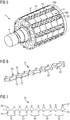
- in einer perspektivischen Darstellung einen Läufer umfassend ein Blechpaket mit aufgebrachtem Klebeband,
- FIG 2
- in einer perspektivischen Darstellung das Blechpaket gemäß
FIG 1 mit fixierten Pollückenstäben und Magneten, - FIG 3
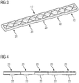
- in einer perspektivischen Darstellung eine erste Ausführungsvariante eines Pollückenstabs,
- FIG 4
- eine Seitenansicht auf einen Pollückenstab gemäß
FIG 3 , - FIG 5
- in einer perspektivischen Darstellung einen zweiten Läufer mit einer zweiten Ausführungsvariante eines Pollückenstabs,
- FIG 6
- in einer perspektivischen Darstellung ein Pollückenstab gemäß
FIG 5 , und - FIG 7
- eine Draufsicht auf einen Pollückenstab gemäß
FIG 5 und FIG 6 . - Gleiche Bezugszeichen haben in den verschiedenen Figuren die gleiche Bedeutung.
- In den
FIG 1 und FIG 2 ist der schrittweise Aufbau eines erfindungsgemäßen Läufers 2 für den Einsatz in einer hier nicht näher gezeigten permanentmagneterregten Synchronmaschine dargestellt, insbesondere in einem Servomotor. Der Läufer 2 umfasst eine sich in einer Axialrichtung A erstreckende Welle 4 und ein Blechpaket 6. - In einem ersten Herstellungsschritt wird das Blechpaket 6 auf die Welle 4 aufgebacht. Im nächsten Schritt wird um den Umfang des Blechpakets 6 Klebeband 8 in mehreren ringförmigen Streifen angebracht. Das Klebeband 8 dient lediglich zum Fixieren von permanenterregen Magneten 10 und ggf. von Pollückenstäben 12, die in einem dritten Schritt auf den Umfang des Blechpakets 6 verteilt werden. Die Magnete 10 sind in diesem Ausführungsbeispiel als Schalenmagnete ausgestaltet und bilden in Axialrichtung mehrere reihenförmige Pole 14.
- Zwischen den Polen 14 sind die Pollückenstäbe 12 angeordnet, welche ein Verrutschen der Magnete 10 verhindern. Die Pollückenstäbe 12 sind hierbei alle gleich breit und gleich lang und sind aus einem magnetisch nicht leitenden Material, z.B. Aluminium oder Kunststoff ausgebildet. Jeder Magnet 10 weist eine erste, sich in Axialrichtung A ersteckende Seite 16a und eine gegenüberliege zweite, sich in Axialrichtung A erstreckende Seite 16b auf. Die Pollückenstäbe 12 sind dabei so positioniert, dass jeder Magnet 10 mit seiner ersten Seite 16a an einem Pollückenstab 12 anliegt und mit seiner zweiten Seite 16b an einem weiteren Pollückenstab 12 anliegt. Im Ausführungsbeispiel gemäß
FIG 1 und FIG 2 liegen die Magnete 12 vollflächig mit ihrer ersten Seite 16a und zweiten Seite 16b an, d.h. es erfolgt ein Kontakt zwischen dem Magneten 10 und dem anliegenden Pollückenstab 12 insbesondere über die gesamte Länge der Seiten 16a, 16b. - In einem letzten Herstellungsschritt wird der Läufer 2 mittels einer hier nicht näher gezeigten Bandage bandagiert. Zur Aufnahme des Bandageanfangs bzw. Bandageendes ist eine Endscheibe 18 vorgesehen. Ihre Funktion kann jedoch von den Pollückenstäben 12 übernommen werden.
- In den
FIG 3 und FIG 4 ist eine erste Ausführungsvariante der Pollückenstäbe 12 gezeigt. Die Pollückenstäbe 12 weisen mehrere Abschnitte 20 auf, die in Axialrichtung A betrachtet zueinander versetzt sind. Darüber hinaus weisen die Pollückenstäbe 12 Zapfen 22 auf, welche radial nach innen gerichtet sind und die Pollückenstäbe 12 über eine formschlüssige Verbindung am Blechpaket 6 fixieren. An ihrer äußeren Seite weisen die Pollückenstäbe 12 eine gitterförmige Profilierung auf. - Eine zweite Ausführungsvariante der Pollückenstäbe 12 ist aus
FIG 5 bis FIG 7 ersichtlich. Die Pollückenstäbe 12 weisen hierbei mehrere quer zur Axialrichtung A verlaufende Stege 24 auf, über welche sie die Seiten 16a, 16b der Magnete 10 punktuell kontaktieren. Die Pollückenstäbe 12 weisen somit im weiteren Sinne eine Fischgrätenform auf. Im gezeigten Ausführungsbeispiel wird dabei jede Seite 16a, 16b eines Magnets 10 von zwei Stegen 24 gestützt. Wie insbesondere ausFIG 7 ersichtlich ist, weisen die Pollückenstäbe 12 der zweiten Ausführungsvariante ebenfalls mehrere Abschnitte 20 auf, wobei die Länge der Stege 24 zwischen den unterschiedlichen Abschnitten 20 variiert wird, damit eine Staffelung der Magnete 10 in Axialrichtung A ermöglicht wird. - Die Pollückenstäbe 12 beider Ausführungsvarianten weisen zudem aufgrund ihrer profilierten Oberfläche im zusammengebauten Zustand des Läufers 2 mehrere Zwischenräume 26 auf, die zumindest radial nach außen offen sind (siehe
FIG 2 undFIG 5 ). Diese hohlen Zwischenräume können insbesondere zum Wuchten des Läufers 2 genutzt werden.
Claims (13)
- Läufer (2) für eine permanentmagneterregte Synchronmaschine, umfassend ein auf einer sich in Axialrichtung (A) erstreckenden Welle (4) angeordnetes Blechpaket (6), um dessen Umfang mehrere Pole (14) angeordnet sind, wobei pro Pol mindestens ein Magnet (10) vorgesehen ist, wobei Pollückenstäbe (12) zwischen den Polen (14) derart positioniert sind, dass in Umfangsrichtung betrachtet jeder Magnet (10) mit einer ersten Seite (16a) und einer gegenüberliegenden zweiten Seite (16b) jeweils an einem Pollückenstab (12) anliegt,
dadurch gekennzeichnet, dass die Pollückenstäbe (12) mindestens zwei Abschnitte (20) aufweisen, die in Axialrichtung (A) betrachtet zueinander versetzt sind, damit eine Staffelung der Magnete (10) in Axialrichtung (A) ermöglicht wird. - Läufer (2) nach Anspruch 1,
dadurch gekennzeichnet, dass die Pollückenstäbe (12) mindestens so lang sind wie die Pole (14). - Läufer (2) nach Anspruch 1 oder 2,
dadurch gekennzeichnet, dass die Pollückenstäbe (12) aus einem magnetisch nicht leitenden Material ausgebildet sind. - Läufer (2) nach einem der vorhergehenden Ansprüche,
dadurch gekennzeichnet, dass die Pollückenstäbe (12) am Blechpaket (6) fixiert sind. - Läufer (2) nach Anspruch 4,
dadurch gekennzeichnet, dass die Pollückenstäbe (12) Zapfen (22) aufweisen, welche radial nach innen gerichtet sind und in Pollücken zwischen den Polen (14) greifen. - Läufer (2) nach einem der vorhergehenden Ansprüche,
dadurch gekennzeichnet, dass die Pollückenstäbe (12) vollflächig mit der ersten und der zweiten Seite (16a, 16b) der Magnete (10) in Kontakt stehen. - Läufer (2) nach einem der Ansprüche 1 bis 5,
dadurch gekennzeichnet, dass die Pollückenstäben (12) mehrere quer zur Axialrichtung (A) sich erstreckende Stege (24) aufweisen, über welche sie die Magnete (10) kontaktieren. - Läufer (2) nach einem der vorhergehenden Ansprüche,
dadurch gekennzeichnet, dass die Magnete (2) als Schalenmagnete ausgebildet sind. - Läufer (2) nach einem der vorhergehenden Ansprüche,
dadurch gekennzeichnet, dass auf dem Blechpaket (6) unterhalb der Magnete (10) Klebeband (8) aufgebracht ist. - Läufer (2) nach einem der vorhergehenden Ansprüche,
dadurch gekennzeichnet, dass die Anordnung von Magneten (10) und Pollückenstäben (12) bandagiert ist. - Läufer (2) nach einem der vorhergehenden Ansprüche,
dadurch gekennzeichnet, dass die Pollückenstäbe (12) mehrere radial nach außen offene Zwischenräume (26) aufweisen. - Pollückenstab (12) für einen Läufer (2) nach einem der vorhergehenden Ansprüche, dadurch gekennzeichnet, dass der Pollückenstab (12) mindestens zwei Abschnitte (20) aufweist, die in Axialrichtung (A) betrachtet zueinander versetzt sind, damit eine Staffelung der Magnete (10) in Axialrichtung (A) ermöglicht wird.
- Verfahren zum Herstellen eines Läufers (2) nach einem der Ansprüche 1 bis 12, dadurch gekennzeichnet, dass- das Blechpaket (6) auf die Welle (4) gefügt wird,- Klebeband (8) zum Vorfixieren der Magnete (10) um den Umfang des Blechpakets (6) aufgebracht wird,- die Pollückenstäbe (12) und die Magnete (10) angeordnet werden, und- der Läufer (2) bandagiert wird.
Applications Claiming Priority (2)
| Application Number | Priority Date | Filing Date | Title |
|---|---|---|---|
| EP16154281.6A EP3203609A1 (de) | 2016-02-04 | 2016-02-04 | Läufer für eine permanentmagneterregte synchronmaschine, pollückenstab für einen solchen läufer und verfahren zum herstellen eines solchen läufers |
| PCT/EP2016/077256 WO2017133800A1 (de) | 2016-02-04 | 2016-11-10 | Läufer für eine permanentmagneterregte synchronmaschine, pollückenstab für einen solchen läufer und verfahren zum herstellen eines solchen läufers |
Publications (2)
| Publication Number | Publication Date |
|---|---|
| EP3391511A1 EP3391511A1 (de) | 2018-10-24 |
| EP3391511B1 true EP3391511B1 (de) | 2019-12-25 |
Family
ID=55299400
Family Applications (2)
| Application Number | Title | Priority Date | Filing Date |
|---|---|---|---|
| EP16154281.6A Withdrawn EP3203609A1 (de) | 2016-02-04 | 2016-02-04 | Läufer für eine permanentmagneterregte synchronmaschine, pollückenstab für einen solchen läufer und verfahren zum herstellen eines solchen läufers |
| EP16795296.9A Active EP3391511B1 (de) | 2016-02-04 | 2016-11-10 | Läufer für eine permanentmagneterregte synchronmaschine, pollückenstab für einen solchen läufer und verfahren zum herstellen eines solchen läufers |
Family Applications Before (1)
| Application Number | Title | Priority Date | Filing Date |
|---|---|---|---|
| EP16154281.6A Withdrawn EP3203609A1 (de) | 2016-02-04 | 2016-02-04 | Läufer für eine permanentmagneterregte synchronmaschine, pollückenstab für einen solchen läufer und verfahren zum herstellen eines solchen läufers |
Country Status (5)
| Country | Link |
|---|---|
| US (1) | US11075554B2 (de) |
| EP (2) | EP3203609A1 (de) |
| JP (1) | JP6639688B2 (de) |
| CN (1) | CN108475949B (de) |
| WO (1) | WO2017133800A1 (de) |
Families Citing this family (2)
| Publication number | Priority date | Publication date | Assignee | Title |
|---|---|---|---|---|
| DE102019213448A1 (de) * | 2019-09-04 | 2021-03-04 | Volkswagen Aktiengesellschaft | Rotor für eine elektrische Maschine mit stegförmigen Halteelementen |
| US20230231429A1 (en) * | 2022-01-18 | 2023-07-20 | Steering Solutions Ip Holding Corporation | Shaped magnet structures for permanent magnet synchronous machines and method of making |
Family Cites Families (34)
| Publication number | Priority date | Publication date | Assignee | Title |
|---|---|---|---|---|
| JPS61138375U (de) | 1985-02-15 | 1986-08-27 | ||
| FR2685571A1 (fr) * | 1991-12-20 | 1993-06-25 | Valeo Systemes Dessuyage | Rotor a aimants permanents, et machine magneto-dynamique, comme un moteur sans collecteur, equipee d'un tel rotor. |
| JPH099539A (ja) * | 1995-06-23 | 1997-01-10 | Meidensha Corp | 永久磁石回転電機の回転子 |
| DE10041329A1 (de) * | 2000-08-23 | 2002-03-14 | Siemens Ag | Permanentmagneterregter Läufer für einen permanentmagneterregten elektrischen Antrieb, insbesondere für AC-Hauptantriebe |
| JP2004236373A (ja) | 2003-01-28 | 2004-08-19 | Tsunehiko Yamazaki | ブラシレスモータ |
| US7692356B2 (en) | 2003-06-20 | 2010-04-06 | Siemens Aktiengesellschaft | Electric machine with a circuit support |
| EP1578003A1 (de) | 2004-03-08 | 2005-09-21 | Siemens Aktiengesellschaft | Elektrische Maschine mit einer Vorrichtung zur Verschaltung von Leitungen des Wicklungssystems |
| JP2005354768A (ja) * | 2004-06-09 | 2005-12-22 | Okuma Corp | 表面磁石型界磁ロータ及びそれを利用したモータ |
| CN1985424B (zh) * | 2004-07-16 | 2010-07-07 | 株式会社美姿把 | 旋转电机的磁铁固定结构 |
| DE102005016855A1 (de) | 2005-04-12 | 2006-10-19 | Siemens Ag | Schnittstellenmodul zur Anordnung in oder an einem Motor |
| DE102005032720B4 (de) | 2005-07-13 | 2007-04-05 | Siemens Ag | Schnittstellenmodulvorrichtung für eine elektrische Maschine zur Lebensdauerberechnung eines Lagers |
| AU2006203333A1 (en) | 2005-08-04 | 2007-02-22 | Lg Electronics Inc | Motor and Motor Manufacturing Method |
| WO2007080888A1 (ja) * | 2006-01-10 | 2007-07-19 | Mitsuba Corporation | 回転電機 |
| CN200944541Y (zh) * | 2006-07-25 | 2007-09-05 | 周剑峰 | 斜槽永磁转子 |
| DE102006049825B4 (de) * | 2006-10-21 | 2012-10-25 | Esw Gmbh | Anordnung zur Befestigung von Permanentmagneten an schnell drehenden Rotoren von elektrischen Maschinen |
| DE102006049866A1 (de) * | 2006-10-23 | 2008-04-30 | Siemens Ag | Elektrische Maschine mit einem auf einem Rotor fixierten Permanentmagneten |
| DE102007013049A1 (de) | 2007-03-19 | 2008-09-25 | Siemens Ag | Verfahren zum Montieren eines Winkelmessgeräts an einem elektrischen Motor |
| DE102007021321A1 (de) | 2007-05-07 | 2008-11-13 | Siemens Ag | Stator mit Stromschienen zum Verschalten der Spulen und entsprechendes Verfahren |
| EP2073352B1 (de) | 2007-12-17 | 2016-03-16 | Siemens Aktiengesellschaft | Permanenterregte Synchronmaschine mit Schalenmagneten |
| EP2139100B1 (de) * | 2008-06-27 | 2012-10-31 | Siemens Aktiengesellschaft | Permanentmagneterregte Synchronmaschine mit reduzierter Drehmomentenwelligkeit |
| EP2151908B1 (de) | 2008-08-04 | 2010-10-06 | Siemens Aktiengesellschaft | Dynamoelektrische Maschine mit einem mehrteiligen Steckergehäuse |
| JP5573109B2 (ja) | 2009-11-05 | 2014-08-20 | 三菱電機株式会社 | 永久磁石式電動機の回転子 |
| CN202535176U (zh) * | 2012-05-23 | 2012-11-14 | 佛山市顺德区金泰德胜电机有限公司 | 永磁转子 |
| CN102684339A (zh) | 2012-05-23 | 2012-09-19 | 佛山市顺德区金泰德胜电机有限公司 | 一种永磁转子 |
| JP2014003795A (ja) | 2012-06-18 | 2014-01-09 | Fuji Electric Co Ltd | 回転子およびその製造方法ならびに永久磁石モータ |
| EP2685607B1 (de) * | 2012-07-09 | 2015-04-01 | Siemens Aktiengesellschaft | Fixierung von Permanentmagneten an einem Rotor |
| CN104113152A (zh) * | 2013-07-10 | 2014-10-22 | 王贤长 | 一种三相异步电动机的永磁转子 |
| EP2824811A1 (de) | 2013-07-11 | 2015-01-14 | Siemens Aktiengesellschaft | Durchgehende, auf Spulenträger gewickelte Statorwicklung |
| EP2978102B1 (de) | 2014-07-22 | 2017-02-22 | Siemens Aktiengesellschaft | Verfahren zur Herstellung eines Rotors |
| CN104638793B (zh) * | 2015-03-12 | 2017-04-19 | 成都银河磁体股份有限公司 | 一种永磁转子以及该转子的制作方法 |
| EP3076524B1 (de) | 2015-03-30 | 2019-02-20 | Siemens Aktiengesellschaft | Maschinenkomponente einer elektrischen maschine und verfahren zu deren herstellung |
| EP3089328B1 (de) | 2015-04-27 | 2017-04-19 | Siemens Aktiengesellschaft | Rotor einer elektrischen maschine |
| CN104838793B (zh) | 2015-04-30 | 2017-01-18 | 昆明理工大学 | 一种四轮拖拉机牵引的滚动栅式三七收获机 |
| CN105048677A (zh) * | 2015-08-31 | 2015-11-11 | 永济新时速电机电器有限责任公司 | 一种磁钢组件式结构的直驱永磁转子 |
-
2016
- 2016-02-04 EP EP16154281.6A patent/EP3203609A1/de not_active Withdrawn
- 2016-11-10 CN CN201680072900.4A patent/CN108475949B/zh active Active
- 2016-11-10 JP JP2018538756A patent/JP6639688B2/ja active Active
- 2016-11-10 WO PCT/EP2016/077256 patent/WO2017133800A1/de not_active Ceased
- 2016-11-10 US US16/075,502 patent/US11075554B2/en active Active
- 2016-11-10 EP EP16795296.9A patent/EP3391511B1/de active Active
Non-Patent Citations (1)
| Title |
|---|
| None * |
Also Published As
| Publication number | Publication date |
|---|---|
| EP3203609A1 (de) | 2017-08-09 |
| US11075554B2 (en) | 2021-07-27 |
| CN108475949B (zh) | 2021-03-02 |
| EP3391511A1 (de) | 2018-10-24 |
| US20190074737A1 (en) | 2019-03-07 |
| WO2017133800A1 (de) | 2017-08-10 |
| JP2019504606A (ja) | 2019-02-14 |
| JP6639688B2 (ja) | 2020-02-05 |
| CN108475949A (zh) | 2018-08-31 |
Similar Documents
| Publication | Publication Date | Title |
|---|---|---|
| EP2639935B1 (de) | Rotor mit Permanenterregung, elektrische Maschine mit einem solchen Rotor und Herstellungsverfahren für den Rotor | |
| EP2973945B1 (de) | Einzelsegmentläufer mit durch biegeträger gehaltenen einzelsegmenten und herstellungsverfahren | |
| EP2696469B1 (de) | Rotor für eine permanent erregte Synchronmaschine | |
| DE102010001481A1 (de) | Rotor einer permanenterregten Synchronmaschine | |
| DE102012107610A1 (de) | Elektromotor | |
| DE102009017850A1 (de) | Läufer für eine elektrische Maschine | |
| DE112014007129T5 (de) | Statorkern für eine elektrische Rotationsmaschine, elektrische Rotationsmaschine und Verfahren zur Herstellung einer elektrischen Rotationsmaschine | |
| EP2965403B1 (de) | Rotor für einen reluktanzmotor, verfahren zum herstellen eines rotors für einen reluktanzmotor sowie elektrische maschine, insbesondere ein reluktanzmotor | |
| WO2011039143A2 (de) | Rotor | |
| DE112017005282T5 (de) | Rotor für rotierende elektrische Maschine | |
| DE102007022835A1 (de) | Rotor für permanentmagnetisch erregte Elektromaschinen | |
| EP2685607A1 (de) | Fixierung von Permanentmagneten an einem Rotor | |
| WO2019171218A1 (de) | Rotoreinheit und elektromotor | |
| DE102005042543A1 (de) | Permanenterregte Synchronmaschine | |
| EP2704294A1 (de) | Rotor einer permanenterregten Synchronmaschine | |
| EP2942858B1 (de) | Rotorblechpaket | |
| EP3076520B1 (de) | Rotor für eine elektrische maschine und herstellungsverfahren | |
| WO2011091791A2 (de) | Befestigungselement zum befestigen eines magneten an einem bauteil einer elektrischen maschine, eine baugruppe sowie bauteil mit einem solchen befestigungselement | |
| WO2019171219A1 (de) | Rotoreinheit und elektromotor | |
| DE102011089985B4 (de) | Verfahren zur Herstellung eines Rotors einer Transversalflussmaschine | |
| EP3203609A1 (de) | Läufer für eine permanentmagneterregte synchronmaschine, pollückenstab für einen solchen läufer und verfahren zum herstellen eines solchen läufers | |
| EP2597752B1 (de) | Lamellenstapel für Rotoren und/oder Statoren von Elektromotoren und Generatoren, Rotor mit einem solchen Lamellenstapel | |
| DE102011002327A1 (de) | Permanentmagnetläufer | |
| EP3208912A1 (de) | Läufer | |
| DE202013012411U1 (de) | Rotor für eine elektrische Maschine |
Legal Events
| Date | Code | Title | Description |
|---|---|---|---|
| STAA | Information on the status of an ep patent application or granted ep patent |
Free format text: STATUS: UNKNOWN |
|
| STAA | Information on the status of an ep patent application or granted ep patent |
Free format text: STATUS: THE INTERNATIONAL PUBLICATION HAS BEEN MADE |
|
| PUAI | Public reference made under article 153(3) epc to a published international application that has entered the european phase |
Free format text: ORIGINAL CODE: 0009012 |
|
| STAA | Information on the status of an ep patent application or granted ep patent |
Free format text: STATUS: REQUEST FOR EXAMINATION WAS MADE |
|
| 17P | Request for examination filed |
Effective date: 20180717 |
|
| AK | Designated contracting states |
Kind code of ref document: A1 Designated state(s): AL AT BE BG CH CY CZ DE DK EE ES FI FR GB GR HR HU IE IS IT LI LT LU LV MC MK MT NL NO PL PT RO RS SE SI SK SM TR |
|
| AX | Request for extension of the european patent |
Extension state: BA ME |
|
| DAV | Request for validation of the european patent (deleted) | ||
| DAX | Request for extension of the european patent (deleted) | ||
| GRAP | Despatch of communication of intention to grant a patent |
Free format text: ORIGINAL CODE: EPIDOSNIGR1 |
|
| STAA | Information on the status of an ep patent application or granted ep patent |
Free format text: STATUS: GRANT OF PATENT IS INTENDED |
|
| INTG | Intention to grant announced |
Effective date: 20190812 |
|
| GRAS | Grant fee paid |
Free format text: ORIGINAL CODE: EPIDOSNIGR3 |
|
| GRAA | (expected) grant |
Free format text: ORIGINAL CODE: 0009210 |
|
| STAA | Information on the status of an ep patent application or granted ep patent |
Free format text: STATUS: THE PATENT HAS BEEN GRANTED |
|
| AK | Designated contracting states |
Kind code of ref document: B1 Designated state(s): AL AT BE BG CH CY CZ DE DK EE ES FI FR GB GR HR HU IE IS IT LI LT LU LV MC MK MT NL NO PL PT RO RS SE SI SK SM TR |
|
| REG | Reference to a national code |
Ref country code: GB Ref legal event code: FG4D Free format text: NOT ENGLISH |
|
| REG | Reference to a national code |
Ref country code: CH Ref legal event code: EP |
|
| REG | Reference to a national code |
Ref country code: AT Ref legal event code: REF Ref document number: 1218215 Country of ref document: AT Kind code of ref document: T Effective date: 20200115 |
|
| REG | Reference to a national code |
Ref country code: DE Ref legal event code: R096 Ref document number: 502016008173 Country of ref document: DE |
|
| REG | Reference to a national code |
Ref country code: IE Ref legal event code: FG4D Free format text: LANGUAGE OF EP DOCUMENT: GERMAN |
|
| REG | Reference to a national code |
Ref country code: NL Ref legal event code: MP Effective date: 20191225 |
|
| PG25 | Lapsed in a contracting state [announced via postgrant information from national office to epo] |
Ref country code: BG Free format text: LAPSE BECAUSE OF FAILURE TO SUBMIT A TRANSLATION OF THE DESCRIPTION OR TO PAY THE FEE WITHIN THE PRESCRIBED TIME-LIMIT Effective date: 20200325 Ref country code: FI Free format text: LAPSE BECAUSE OF FAILURE TO SUBMIT A TRANSLATION OF THE DESCRIPTION OR TO PAY THE FEE WITHIN THE PRESCRIBED TIME-LIMIT Effective date: 20191225 Ref country code: NO Free format text: LAPSE BECAUSE OF FAILURE TO SUBMIT A TRANSLATION OF THE DESCRIPTION OR TO PAY THE FEE WITHIN THE PRESCRIBED TIME-LIMIT Effective date: 20200325 Ref country code: GR Free format text: LAPSE BECAUSE OF FAILURE TO SUBMIT A TRANSLATION OF THE DESCRIPTION OR TO PAY THE FEE WITHIN THE PRESCRIBED TIME-LIMIT Effective date: 20200326 Ref country code: LT Free format text: LAPSE BECAUSE OF FAILURE TO SUBMIT A TRANSLATION OF THE DESCRIPTION OR TO PAY THE FEE WITHIN THE PRESCRIBED TIME-LIMIT Effective date: 20191225 Ref country code: LV Free format text: LAPSE BECAUSE OF FAILURE TO SUBMIT A TRANSLATION OF THE DESCRIPTION OR TO PAY THE FEE WITHIN THE PRESCRIBED TIME-LIMIT Effective date: 20191225 Ref country code: SE Free format text: LAPSE BECAUSE OF FAILURE TO SUBMIT A TRANSLATION OF THE DESCRIPTION OR TO PAY THE FEE WITHIN THE PRESCRIBED TIME-LIMIT Effective date: 20191225 |
|
| REG | Reference to a national code |
Ref country code: LT Ref legal event code: MG4D |
|
| PG25 | Lapsed in a contracting state [announced via postgrant information from national office to epo] |
Ref country code: RS Free format text: LAPSE BECAUSE OF FAILURE TO SUBMIT A TRANSLATION OF THE DESCRIPTION OR TO PAY THE FEE WITHIN THE PRESCRIBED TIME-LIMIT Effective date: 20191225 Ref country code: HR Free format text: LAPSE BECAUSE OF FAILURE TO SUBMIT A TRANSLATION OF THE DESCRIPTION OR TO PAY THE FEE WITHIN THE PRESCRIBED TIME-LIMIT Effective date: 20191225 |
|
| PG25 | Lapsed in a contracting state [announced via postgrant information from national office to epo] |
Ref country code: AL Free format text: LAPSE BECAUSE OF FAILURE TO SUBMIT A TRANSLATION OF THE DESCRIPTION OR TO PAY THE FEE WITHIN THE PRESCRIBED TIME-LIMIT Effective date: 20191225 |
|
| PG25 | Lapsed in a contracting state [announced via postgrant information from national office to epo] |
Ref country code: EE Free format text: LAPSE BECAUSE OF FAILURE TO SUBMIT A TRANSLATION OF THE DESCRIPTION OR TO PAY THE FEE WITHIN THE PRESCRIBED TIME-LIMIT Effective date: 20191225 Ref country code: NL Free format text: LAPSE BECAUSE OF FAILURE TO SUBMIT A TRANSLATION OF THE DESCRIPTION OR TO PAY THE FEE WITHIN THE PRESCRIBED TIME-LIMIT Effective date: 20191225 Ref country code: RO Free format text: LAPSE BECAUSE OF FAILURE TO SUBMIT A TRANSLATION OF THE DESCRIPTION OR TO PAY THE FEE WITHIN THE PRESCRIBED TIME-LIMIT Effective date: 20191225 Ref country code: PT Free format text: LAPSE BECAUSE OF FAILURE TO SUBMIT A TRANSLATION OF THE DESCRIPTION OR TO PAY THE FEE WITHIN THE PRESCRIBED TIME-LIMIT Effective date: 20200520 Ref country code: CZ Free format text: LAPSE BECAUSE OF FAILURE TO SUBMIT A TRANSLATION OF THE DESCRIPTION OR TO PAY THE FEE WITHIN THE PRESCRIBED TIME-LIMIT Effective date: 20191225 |
|
| PG25 | Lapsed in a contracting state [announced via postgrant information from national office to epo] |
Ref country code: SK Free format text: LAPSE BECAUSE OF FAILURE TO SUBMIT A TRANSLATION OF THE DESCRIPTION OR TO PAY THE FEE WITHIN THE PRESCRIBED TIME-LIMIT Effective date: 20191225 Ref country code: IS Free format text: LAPSE BECAUSE OF FAILURE TO SUBMIT A TRANSLATION OF THE DESCRIPTION OR TO PAY THE FEE WITHIN THE PRESCRIBED TIME-LIMIT Effective date: 20200425 Ref country code: SM Free format text: LAPSE BECAUSE OF FAILURE TO SUBMIT A TRANSLATION OF THE DESCRIPTION OR TO PAY THE FEE WITHIN THE PRESCRIBED TIME-LIMIT Effective date: 20191225 |
|
| REG | Reference to a national code |
Ref country code: DE Ref legal event code: R097 Ref document number: 502016008173 Country of ref document: DE |
|
| PG25 | Lapsed in a contracting state [announced via postgrant information from national office to epo] |
Ref country code: ES Free format text: LAPSE BECAUSE OF FAILURE TO SUBMIT A TRANSLATION OF THE DESCRIPTION OR TO PAY THE FEE WITHIN THE PRESCRIBED TIME-LIMIT Effective date: 20191225 Ref country code: DK Free format text: LAPSE BECAUSE OF FAILURE TO SUBMIT A TRANSLATION OF THE DESCRIPTION OR TO PAY THE FEE WITHIN THE PRESCRIBED TIME-LIMIT Effective date: 20191225 |
|
| PLBE | No opposition filed within time limit |
Free format text: ORIGINAL CODE: 0009261 |
|
| STAA | Information on the status of an ep patent application or granted ep patent |
Free format text: STATUS: NO OPPOSITION FILED WITHIN TIME LIMIT |
|
| PG25 | Lapsed in a contracting state [announced via postgrant information from national office to epo] |
Ref country code: SI Free format text: LAPSE BECAUSE OF FAILURE TO SUBMIT A TRANSLATION OF THE DESCRIPTION OR TO PAY THE FEE WITHIN THE PRESCRIBED TIME-LIMIT Effective date: 20191225 |
|
| 26N | No opposition filed |
Effective date: 20200928 |
|
| PG25 | Lapsed in a contracting state [announced via postgrant information from national office to epo] |
Ref country code: PL Free format text: LAPSE BECAUSE OF FAILURE TO SUBMIT A TRANSLATION OF THE DESCRIPTION OR TO PAY THE FEE WITHIN THE PRESCRIBED TIME-LIMIT Effective date: 20191225 |
|
| REG | Reference to a national code |
Ref country code: CH Ref legal event code: NV Representative=s name: SIEMENS SCHWEIZ AG, CH |
|
| PG25 | Lapsed in a contracting state [announced via postgrant information from national office to epo] |
Ref country code: MC Free format text: LAPSE BECAUSE OF FAILURE TO SUBMIT A TRANSLATION OF THE DESCRIPTION OR TO PAY THE FEE WITHIN THE PRESCRIBED TIME-LIMIT Effective date: 20191225 |
|
| REG | Reference to a national code |
Ref country code: CH Ref legal event code: PL |
|
| GBPC | Gb: european patent ceased through non-payment of renewal fee |
Effective date: 20201110 |
|
| PG25 | Lapsed in a contracting state [announced via postgrant information from national office to epo] |
Ref country code: LU Free format text: LAPSE BECAUSE OF NON-PAYMENT OF DUE FEES Effective date: 20201110 |
|
| REG | Reference to a national code |
Ref country code: BE Ref legal event code: MM Effective date: 20201130 |
|
| PG25 | Lapsed in a contracting state [announced via postgrant information from national office to epo] |
Ref country code: CH Free format text: LAPSE BECAUSE OF NON-PAYMENT OF DUE FEES Effective date: 20201130 Ref country code: LI Free format text: LAPSE BECAUSE OF NON-PAYMENT OF DUE FEES Effective date: 20201130 |
|
| PG25 | Lapsed in a contracting state [announced via postgrant information from national office to epo] |
Ref country code: IE Free format text: LAPSE BECAUSE OF NON-PAYMENT OF DUE FEES Effective date: 20201110 |
|
| PG25 | Lapsed in a contracting state [announced via postgrant information from national office to epo] |
Ref country code: GB Free format text: LAPSE BECAUSE OF NON-PAYMENT OF DUE FEES Effective date: 20201110 |
|
| PG25 | Lapsed in a contracting state [announced via postgrant information from national office to epo] |
Ref country code: TR Free format text: LAPSE BECAUSE OF FAILURE TO SUBMIT A TRANSLATION OF THE DESCRIPTION OR TO PAY THE FEE WITHIN THE PRESCRIBED TIME-LIMIT Effective date: 20191225 Ref country code: MT Free format text: LAPSE BECAUSE OF FAILURE TO SUBMIT A TRANSLATION OF THE DESCRIPTION OR TO PAY THE FEE WITHIN THE PRESCRIBED TIME-LIMIT Effective date: 20191225 Ref country code: CY Free format text: LAPSE BECAUSE OF FAILURE TO SUBMIT A TRANSLATION OF THE DESCRIPTION OR TO PAY THE FEE WITHIN THE PRESCRIBED TIME-LIMIT Effective date: 20191225 |
|
| PG25 | Lapsed in a contracting state [announced via postgrant information from national office to epo] |
Ref country code: MK Free format text: LAPSE BECAUSE OF FAILURE TO SUBMIT A TRANSLATION OF THE DESCRIPTION OR TO PAY THE FEE WITHIN THE PRESCRIBED TIME-LIMIT Effective date: 20191225 |
|
| PG25 | Lapsed in a contracting state [announced via postgrant information from national office to epo] |
Ref country code: BE Free format text: LAPSE BECAUSE OF NON-PAYMENT OF DUE FEES Effective date: 20201130 |
|
| REG | Reference to a national code |
Ref country code: AT Ref legal event code: MM01 Ref document number: 1218215 Country of ref document: AT Kind code of ref document: T Effective date: 20211110 |
|
| PG25 | Lapsed in a contracting state [announced via postgrant information from national office to epo] |
Ref country code: AT Free format text: LAPSE BECAUSE OF NON-PAYMENT OF DUE FEES Effective date: 20211110 |
|
| PGFP | Annual fee paid to national office [announced via postgrant information from national office to epo] |
Ref country code: DE Payment date: 20250120 Year of fee payment: 9 |
|
| PGFP | Annual fee paid to national office [announced via postgrant information from national office to epo] |
Ref country code: IT Payment date: 20251125 Year of fee payment: 10 |
|
| PGFP | Annual fee paid to national office [announced via postgrant information from national office to epo] |
Ref country code: FR Payment date: 20251114 Year of fee payment: 10 |