EP3390962B1 - Maschine zum messen und sortieren von baugruppenteilen vom typ senkkopfniete - Google Patents
Maschine zum messen und sortieren von baugruppenteilen vom typ senkkopfniete Download PDFInfo
- Publication number
- EP3390962B1 EP3390962B1 EP16825470.4A EP16825470A EP3390962B1 EP 3390962 B1 EP3390962 B1 EP 3390962B1 EP 16825470 A EP16825470 A EP 16825470A EP 3390962 B1 EP3390962 B1 EP 3390962B1
- Authority
- EP
- European Patent Office
- Prior art keywords
- camera
- head
- image
- measurement
- parts
- Prior art date
- Legal status (The legal status is an assumption and is not a legal conclusion. Google has not performed a legal analysis and makes no representation as to the accuracy of the status listed.)
- Active
Links
Images

Classifications
-
- B—PERFORMING OPERATIONS; TRANSPORTING
- B07—SEPARATING SOLIDS FROM SOLIDS; SORTING
- B07C—POSTAL SORTING; SORTING INDIVIDUAL ARTICLES, OR BULK MATERIAL FIT TO BE SORTED PIECE-MEAL, e.g. BY PICKING
- B07C5/00—Sorting according to a characteristic or feature of the articles or material being sorted, e.g. by control effected by devices which detect or measure such characteristic or feature; Sorting by manually actuated devices, e.g. switches
- B07C5/04—Sorting according to size
- B07C5/10—Sorting according to size measured by light-responsive means
-
- B—PERFORMING OPERATIONS; TRANSPORTING
- B07—SEPARATING SOLIDS FROM SOLIDS; SORTING
- B07C—POSTAL SORTING; SORTING INDIVIDUAL ARTICLES, OR BULK MATERIAL FIT TO BE SORTED PIECE-MEAL, e.g. BY PICKING
- B07C5/00—Sorting according to a characteristic or feature of the articles or material being sorted, e.g. by control effected by devices which detect or measure such characteristic or feature; Sorting by manually actuated devices, e.g. switches
- B07C5/36—Sorting apparatus characterised by the means used for distribution
-
- G—PHYSICS
- G01—MEASURING; TESTING
- G01B—MEASURING LENGTH, THICKNESS OR SIMILAR LINEAR DIMENSIONS; MEASURING ANGLES; MEASURING AREAS; MEASURING IRREGULARITIES OF SURFACES OR CONTOURS
- G01B11/00—Measuring arrangements characterised by the use of optical techniques
- G01B11/02—Measuring arrangements characterised by the use of optical techniques for measuring length, width or thickness
-
- G—PHYSICS
- G01—MEASURING; TESTING
- G01B—MEASURING LENGTH, THICKNESS OR SIMILAR LINEAR DIMENSIONS; MEASURING ANGLES; MEASURING AREAS; MEASURING IRREGULARITIES OF SURFACES OR CONTOURS
- G01B11/00—Measuring arrangements characterised by the use of optical techniques
- G01B11/08—Measuring arrangements characterised by the use of optical techniques for measuring diameters
-
- G—PHYSICS
- G01—MEASURING; TESTING
- G01B—MEASURING LENGTH, THICKNESS OR SIMILAR LINEAR DIMENSIONS; MEASURING ANGLES; MEASURING AREAS; MEASURING IRREGULARITIES OF SURFACES OR CONTOURS
- G01B11/00—Measuring arrangements characterised by the use of optical techniques
- G01B11/24—Measuring arrangements characterised by the use of optical techniques for measuring contours or curvatures
-
- G—PHYSICS
- G01—MEASURING; TESTING
- G01B—MEASURING LENGTH, THICKNESS OR SIMILAR LINEAR DIMENSIONS; MEASURING ANGLES; MEASURING AREAS; MEASURING IRREGULARITIES OF SURFACES OR CONTOURS
- G01B11/00—Measuring arrangements characterised by the use of optical techniques
- G01B11/26—Measuring arrangements characterised by the use of optical techniques for measuring angles or tapers; for testing the alignment of axes
-
- B—PERFORMING OPERATIONS; TRANSPORTING
- B07—SEPARATING SOLIDS FROM SOLIDS; SORTING
- B07C—POSTAL SORTING; SORTING INDIVIDUAL ARTICLES, OR BULK MATERIAL FIT TO BE SORTED PIECE-MEAL, e.g. BY PICKING
- B07C2501/00—Sorting according to a characteristic or feature of the articles or material to be sorted
- B07C2501/0009—Sorting of fasteners, e.g. screws, nuts, bolts
Definitions
- the invention relates to machines for measuring and sorting assembly parts of rivets with countersunk heads, in particular for an aeronautical application.
- the standards known by the acronyms ASNA 2019, ASNA 2051 or EN6100 classify the rivets in particular according to the diameter of their head.
- ASNA 2019 standard the rivets referenced 40 all have a head whose diameter is between 6.20 mm and 6.78 mm while the rivets referenced 48 all have a head whose diameter is between 7.87 mm and 8.47 mm.
- the diameters of the heads may have a difference of the order of 0.5 mm.
- the misalignment tolerance is stricter than the tolerance on the diameter of the rivet heads. It is therefore in practice difficult and very restrictive to respect the constraints of misalignment for all rivets from the same reference class.
- the operators must carry out milling on the aircraft which are functions of the assembly parts which they have. In other words, they must adapt the bore to the exact dimensions of the assembly part, including its diameter. This requires measuring the exact dimensions of the assembly part and adapting the milling operation accordingly or to mount the parts without worrying about the exact dimensions and then to remove the parts for which it is found after assembly that they do not meet the criteria of misalignment required by the manufacturer. Whatever the solution implemented, it is very time consuming.
- the inventors have therefore imagined putting in place a sorting on the parts supplied by the suppliers to separate each reference class of the assembly parts into a plurality of more precise subclasses making it possible to respond directly to the misalignment constraints imposed by the manufacturers.
- the document DE 10 2014 106 312 A1 presents a machine for measuring, sorting and assembling parts of rivets with countersunk heads.
- This machine comprises a feed tank for the parts to be sorted, a device for conveying the parts to be sorted, optical means for acquiring images of each part, an image processing unit for providing a geometric characteristic of each part. and dispensing means for directing a workpiece having a geometric feature out of the allowable range to a scrap container.
- DE 43 13 829 A1 presents a device for measuring and sorting rivets comprising a camera for capturing images of the head of each rivet and a device for dispensing the rivets to a waste bin and a selection bin according to the measurement results.
- the object of the invention is to provide a machine for measuring and sorting assembly parts, such as countersunk head rivets.
- the object of the invention is in particular to provide a machine for measuring and sorting assembly parts which automatically makes it possible to measure and sort the parts as a function of the measurements made.
- the invention aims in particular to provide, in at least one embodiment, a measuring machine and sorting assembly parts that can measure a plurality of structural characteristics of the parts, and sort the parts as a function of at least one of these measured structural characteristics.
- the invention also aims to provide, in at least one embodiment of the invention, a measuring machine and sorting assembly parts that allows to remove all parts that do not meet predetermined technical specifications.
- the invention also aims to provide, in at least one embodiment, a measuring and sorting machine that can measure and sort the parts at a rate of about 3 pieces per second.
- a machine therefore makes it possible to measure each piece to be sorted by determining at least one measurement of at least one structural characteristic of each piece, and of sorting each piece according to this measurement.
- Each piece is measured by the acquisition of at least one image of this piece and by an analysis of this image by an image processing unit.
- This image processing unit is configured to determine values of certain structural characteristics of each part.
- the processing unit is configured to provide a measure of the total length of the workpiece and / or a measurement of the diameter of the workpiece head, and / or a measure of ovality. the head of the coin, and / or a measure of diameter of the rod of the piece, etc.
- a machine further comprises a plurality of sorted material receiving bins, each tray being associated with a predetermined range of value of at least one structural sorting feature of the parts.
- the structural feature of sorting is the diameter of the heads of the pieces.
- the sorting machine can then distribute the parts to be sorted in each receiving tray according to the diameter of the heads of the parts.
- each tray is associated with a specific range of diameters and distinct from the ranges of the other trays so that all the assembly parts having a measured diameter included in the range of values of a tray are automatically sent to this receiving tray by the distribution means.
- the diameter of the head of the parts serves as a structural sorting feature.
- the invention makes it possible to sort these rivets and to divide them into 5 subclasses for example, each subclass having a maximum dispersion of 0.12 mm.
- the sorting machine can distribute the rivets in 5 receiving bins, a tray associated with the range of values 7.87 mm to 7.99 mm, a tray associated with the range of values 7.99 mm to 8.11 mm, a container associated with the range of values 8.11 mm to 8.23 mm, a container associated with the range of values 8.23 mm to 8.35 mm, a container associated with the range of values 8.35 mm to 8,47 mm, plus a specific designated bin as a waste bin in which non-valuable parts compliant (diameter less than 7.87 and greater than 8.47) are rejected.
- dispersion of each subclass can be parameterized by the machine according to the invention so that it is possible to measure and sort the assembly parts in as many subclasses as necessary according to the specificities of the applications in which these parts of assembly must be used.
- the measurement of the structural characteristics of the assembly parts is performed by optical image acquisition means associated with a processing unit of the images acquired by the optical image acquisition means.
- optical image acquisition means associated with a processing unit of the images acquired by the optical image acquisition means.
- This allows a precise, fast and robust measurement of the different structural characteristics of the parts.
- this simply allows the measuring means to be adapted to different types of assembly parts by modifying the image processing program implemented by the image processing unit, without nevertheless requiring a structural modification of the image processing unit. the measuring and sorting machine.
- a machine comprises gripping means of the parts conveyed by said conveyor, said gripping means being configured to be able to move assembly parts between a position, said gripping position of the parts, in which the parts are on said conveying device, and a position, said shooting position, in which the parts are fixed with respect to said optical image acquisition means.
- the machine comprises gripping means assembly pieces configured to be able to grip the parts on the conveyor and bring them to the optical image acquisition means to perform measurements on the parts to be sorted. This makes it possible to deport the optical image acquisition means of the parts conveying device.
- the gripping means are configured to be able to keep the fixed assembly parts facing the optical image acquisition means.
- the gripping means are configured to be able to bring the rivets to means for holding the assembly parts separate from the gripping means.
- Such holding means are for example formed of a four-jaw flange adapted to maintain a fixed attachment piece for image acquisition of this piece by the optical image acquisition means.
- two types of images are acquired for each assembly part to be measured and sorted, a front image of this part and a profile image of this part so as to be able to determine at the same time structural characteristics.
- front of this piece as structural profile features of this piece.
- an ovalization camera is arranged in the axis of the rod of a piece to be measured held by said gripping means, facing the head, to be able to acquire a front image of the head of this piece and a profile camera is arranged perpendicular to the axis of the rod of the piece, to be able to acquire a side image of this piece.
- a machine comprises a plurality of sorting stations, each sorting station being formed by gripping means, an ovality camera, a profile camera, and means for dispensing parts to said bins. reception.
- a machine according to this variant makes it possible to multiply the number of measurement and sorting by unit of time.
- the machine comprises three sorting stations so that the machine can measure and sort three times more parts than a machine having a single sorting station, the measuring cycle time of each station being 1 second .
- a machine can therefore measure a large number of structural characteristics of the assembly parts to be sorted.
- Each measured structural feature can form a defining sorting structural feature to which receiving bin the sorted parts are directed.
- a machine comprises at least one scrap tray, to which said dispensing means reject each piece of which at least one measurement of at least one structural characteristic provided by said processing unit is not within a predetermined range of values.
- a sorting machine makes it possible to sort the pieces according to at least one sorting structural characteristic.
- the machine according to this variant also makes it possible to test the other structural characteristics of the parts and to reject the parts of which these structural characteristics, hereinafter referred to as secondary characteristics, are not included in a predetermined range of values. These parts are rejected to a waste bin.
- the machine can be parameterized to sort the parts according to the diameter of the head of the parts so that the receiving bins of the machine receive parts according to the diameter of the heads of the parts.
- the diameter of the head of the pieces then serves as a structural sorting feature.
- the machine measures other structural features, such as head ovality, cone angle, stem diameter, and so on. These characteristics are the secondary characteristics, which are not used to sort the pieces into a plurality of subclasses but which are nevertheless measured.
- the machine rejects to a waste bin all the parts whose secondary characteristics do not correspond to predetermined ranges of values.
- the machine can be set to reject all the parts whose measured ovalization is greater than 0.1 mm and / or all the parts whose cone angle is outside tolerance range 99.5 ° to 100.5 °, etc.
- the characteristics tested and the values indicated are given solely by way of example, without limitation.
- the optical means further comprise a camera, called an input camera, arranged at the level of the conveyor, close to the supply tank of the parts to be sorted, this input camera being configured to provide the at least one image, said input image, and said processing unit is configured to be able to provide, from at least one image of each piece acquired by this input camera, a measurement of the total length of the part, a measure of the diameter of the head of this piece, and / or a measurement of the diameter of the rod of this piece.
- a camera called an input camera
- each piece is observed by an input camera and analyzed by the processing unit before being conveyed to the measuring and sorting means (formed by the optical image acquisition means, the processing unit and distribution means).
- the measuring and sorting means formed by the optical image acquisition means, the processing unit and distribution means.
- said dispensing means are configured to reject any piece of waste material to a waste container, at least one measure provided by said processing unit from an image of said input camera is not included in at least a predetermined range of values.
- each part of which one of the structural characteristics determined by the association of the input camera and the processing unit does not correspond to a predetermined range of values is sent directly to a waste container.
- a waste bin is associated with the input camera and a waste bin is associated with each sorting station.
- the parts judged non-compliant by the input camera are directly rejected to the waste bin associated with the input camera and the parts found to be non-compliant after passing through a sorting station are rejected to a waste bin associated with the sorting station.
- Having a waste bin specifically associated with the input camera makes it possible, for example, to quickly recover in the same waste bin all the parts of a batch that does not correspond to the reference that is sought. sorting.
- the parts of the reference not separated by the camera input, but not corresponding to the range of values that we seek to separate, will be rejected to the waste bin of the sorting station.
- said assembly parts are countersunk rivets intended for an aeronautical application.
- the invention also relates to a measuring and sorting machine characterized in combination by all or some of the features mentioned above or below.
- a machine of measuring and sorting of assembly parts comprises a tank 5 for feeding the parts to be sorted.
- the parts to be sorted are countersunk countersunk rivets. That being so, the invention also applies to other assembly parts.
- the condition is that the parts to be sorted comprise a head and a rod connected to the head, the head extending perpendicular to the rod.
- This tank 5 is supplied with rivets manually by an operator.
- a machine according to the invention also comprises a plurality of trays 11, 21, 31 for receiving the rivets to be sorted.
- the machine according to the invention also comprises a device for conveying the rivets to be sorted arranged between the tank 5 and the receiving bins.
- the conveying device comprises a strip 6 for transporting the rivets.
- This conveyor belt preferably has a cross-section V-shaped so as to facilitate the centering of the rivets on the conveyor belt.
- This conveyor belt 6 is for example set in motion by a pinion 7 driven in rotation by an electric motor not shown in the figures.
- the feed tank 5 rivets to be sorted is associated with a vibratory bowl for moving each rivet to the transport strip 6.
- the vibratory bowl can be replaced by two blade hoppers.
- a machine also comprises three sorting stations 10, 20, 30.
- Each sorting station 10, 20, 30 respectively comprises a gripper 12, 22, 32 forming means for gripping the rivets to be sorted, an ovalization camera 13, 23, 33 configured to take a front image of each rivet, a profile camera 14, 24, 34 configured to take a profile image of each rivet, and a funnel 15, 25, 35 forming means for dispensing the rivets to the trays 11, 21, 31 for receiving sorted rivets.
- each sort station is associated with a waste bin. These waste bins sorting stations are referenced 11r, 21r and 31r on the figure 1 .
- a machine also comprises a unit 8 of processing of images acquired by the cameras.
- the processing unit is configured to provide measurements of the structural characteristics of the rivets to be sorted.
- Such a processing unit comprises for example a computer configured to implement one or more modules for processing the images acquired by the cameras.
- module is meant a software element, a subset of a software program, which can be compiled separately, either for independent use, or to be assembled with other modules of a program, or a hardware element, or a combination of a hardware element and a software subprogram.
- Such material element may include an own IC application (known by the acronym ASIC for the English name application-specific integrated circuit) or a programmable logic circuit (better known by the acronym FPGA for the English name Field- Programmable Gate Array ) or a specialized microprocessor circuit (better known by the acronym DSP for the English name Digital Signal Processor ) or any equivalent hardware.
- a module is an element (software and / or hardware) that ensures a function.
- the function provided by a module of the image processing unit is the measurement of one or more structural characteristics of each rivet imaged by the image acquisition means.
- the image processing unit 8 can be connected to the cameras by all types of known communication means, for example by wired means such as wired networks and / or by wireless means such as wireless networks of the wireless network. type network WIFI, Bluetooth, etc.
- wired networks these can indifferently be electrical networks, optical networks, magnetic networks and generally any type of network for transmitting data between an image acquisition camera and a processing unit of these digital images.
- the figure 2 is a detailed view of a sorting station of the machine according to the embodiment of the figure 1 .
- the sorting station is described below in connection with the sorting station referenced 10, it being understood that the other sorting stations referenced 20, 30 preferably have a structure and an operation. identical to the sorting station referenced 10 described below.
- the sorting station 10 comprises a flange 16 comprising four jaws 16a mounted on a support plate 17.
- the jaws 16a are configured to be able, on command, to grip a rivet brought between the jaws 16a by the clamp 12.
- the presence of four jaws 16a regularly distributed allows a good catch and immobilization of each rivet during the acquisition of images.
- the support plate 17 also carries the camera 14 in profile and the camera 13 ovalization.
- the flange 16 is intended to receive each rivet to be measured.
- the clamp 12 forms the means for gripping the rivets between a position, called the rivet gripping position, in which the gripper can grip a rivet on the conveyor belt 6 and a position, called the shooting position, in which the rivet is held in flange 16 with four jaws.
- the clamp 12 is controlled by a moving robot 18.
- a robot 18 is for example a robot known under the trade name Fanuc M1. This robot is set to move the clamp 12 between the capture position and the shooting position.
- the sorting station 10 also comprises an ovalization camera 13, configured to be able to acquire a front image of the head of each rivet brought into the flange 16, and a profile camera 14 configured to be able to acquire a side image of each rivet brought into the flange 16.
- the axes of sight of the cameras 13 ovalization and 14 profile are perpendicular.
- the ovalization camera 13 is a 1 / 1.8 inch CMOS type camera with a resolution of 1600x1200.
- it is associated with a blue LED circular shaving light and a 102mm macro lens.
- the profile camera 14 is for example a CMOS camera 1 / 1.8 inch, having a resolution of 1600x200 associated with a high-resolution teleCentric lens.
- the sorting station 10 also comprises a funnel 15 for dispensing each rivet to the receiving bins 11.
- This funnel 15 comprises an upper opening (not visible in the figures) which opens on the support plate 17 and a free bottom opening arranged facing the receiving bins 11.
- This funnel 15 is pivotally mounted relative to the support plate 17 to be able to bring the lower opening facing the receiving tray to which the measured rivet must be delivered taking into account measurements made by the image processing unit 8.
- the funnel 15 is controlled to be able to move its lower end to the receiving tray designated given the measurement.
- the clamp 12 grasps the rivet 9 in the flange 16 and releases it into the upper opening of the funnel. The rivet then slides into the funnel 15 and comes out to fall into the designated receiving tray taking into account the measurements made.
- the upper opening of the funnel 15 is formed under the flange 16 so that a release of the jaws 16a of the flange 16 directly causes the rivet to fall into the funnel 15.
- the machine further comprises an input camera 50 arranged at the arrival of the rivets 9 on the conveyor belt 6.
- the input camera is for example a camera associated with a lens 25mm.
- This input camera 50 is configured to provide an input image of each rivet transmitted to the processing unit 8.
- the processing unit 8 is configured to be able to provide a measure of the total length of the rivet, a measure of the diameter of the rivet head, and / or a measure of the diameter of the rivet shank. If any of these measures (whose measurement principle is described below) is non-compliant, the rivet is not gripped by the clamp 12 and is rejected to a waste bin 40 without going through sorting stations.
- the waste bin 40 is arranged at the end of the conveyor. This waste bin 40 is intended to receive the non-compliant rivets 9 detected by the input camera 50. According to the embodiment of the figures, the waste bin 40 is arranged at the end of the conveyor belt 6 so that that if a rivet 9 is considered as non-compliant with respect to the program selected by the processing unit 8, the clamp 12 of the sorting station does not take the rivet on the strip 6 of transport that will naturally lead the rivet to the waste bin 40. This tray being arranged under the conveyor belt, the non-compliant rivet will fall by gravity into the waste bin 40.
- the machine also includes a waste bin 11r, 21r, 31r associated with each sorting station. These waste bins 11r, 21r, 31r are intended to receive the rivets considered as non-compliant, but after passing through the sorting station, that is to say that these bins will receive the rivets for which at least one measure of at least one structural characteristic provided by the processing unit 8 is not within a predetermined range of values.
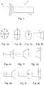
- FIG. 3 An example of a rivet that can be measured and sorted by a machine according to the invention is represented on the figure 3 .
- This rivet 9 comprises a head 9a and a rod 9b.
- the processing unit 8 is configured to be able to measure the structural characteristics of a rivet 9 shown schematically on the Figures 4a to 4i .
- the figure 4a illustrates a measurement of an average diameter of the head 9a of a rivet 9 from a front image of the head acquired by the ovalization camera 13 or from an input image acquired by the camera 50 input. This measurement is made by calculating an average diameter of the head from the measurement of a plurality of diameters of the head. If the diameter does not fall within a predetermined range of values, then the rivet 9 is considered non-compliant and is rejected to the waste bin 40 if it has been detected by the input camera 50 upstream or 11r waste bin associated with the sorting station 10 if it was detected by the ovalization camera 13 downstream.
- the figure 4b illustrates a measure of the ovalization of the head 9a of a rivet 9 from a front image of the head acquired by the ovalization camera 13. This measurement is made by calculating the difference between the maximum diameter measured and the minimum diameter measured. If the difference is greater than a predetermined threshold, then the rivet 9 is considered as non-compliant and is rejected to the waste bin 11r of the sorting station 10.
- the figure 4c illustrates a measurement of an impact on the head 9a of a rivet 9 from a front image of the head acquired by the ovalization camera 13. This measurement is performed by measuring the radial dimension i of an impact, that is to say by measuring the radial dimension from a break in continuity of the periphery of the head. If the distance i measured is greater than a predetermined threshold, then the rivet 9 is considered as non-compliant and is rejected to the waste bin 11r of the sorting station 10.
- the figure 4d illustrates a measurement of the cone angle of the head 9a of a rivet 9 from a side image of the rivet 9 acquired by the camera 14 in profile. This measurement is performed by determining the angle ⁇ between the rod 9b and the head 9b as shown in FIG. figure 4d . If the angle does not fall within a predetermined range of values, then the rivet 9 is considered non-compliant and is rejected to the waste bin 11r of the sorting station 10.
- the figure 4e illustrates a measure of perpendicularity between the head 9a and the rod 9b of a rivet 9 from a profile image of the rivet 9 acquired by the camera 14 in profile. This measurement is performed by determining the angle ⁇ between the rod 9b and the head 9a as shown in FIG. figure 4e . If the angle has a predetermined variation with respect to a 90 ° angle, then the rivet 9 is considered as non-compliant and is rejected to the waste bin 11r of the sorting station 10.
- the figure 4f illustrates a measurement of a beat of the cone of the head 9a with the rod 9b of a rivet 9 from a profile image of the rivet 9 acquired by the camera 14 in profile. If the axis of revolution generated by the measurement of the cone does not fit in a cylinder of predetermined diameter (for example 0.1mm) around the axis generated by the rod, the rivet 9 is considered as non-compliant and is rejected to the waste bin 11r of the sorting station 10.
- a cylinder of predetermined diameter for example 0.1mm
- the figure 4g illustrates a measurement of the distance between a reference diameter of the head and the end of the head 9a of the rivet 9, from a profile image of the rivet 9 acquired by the camera 14 in profile. This measurement is made by determining the position of the reference diameter and the measurement of the distance c between the position of this reference diameter and the end of the head 9a. If this distance deviates from a predetermined range of values, the rivet 9 is considered as non-compliant and is rejected to the waste container 11r of the sorting station 10.
- the figure 4h illustrates a measurement of the diameter of the rod 9b of the rivet 9, to from a profile image of the rivet 9 acquired by the camera 14 in profile or from an input image acquired by the camera 50 input. This measurement is made by determining the diameter t of the rod 9b of the rivet 9. If this diameter t deviates from a predetermined range of values, the rivet 9 is considered as non-compliant and is rejected to the waste bin 40. it was detected by the input camera 50 upstream or to the waste bin 11r of the sorting station 10 if it was detected by the ovalization camera 13 located downstream.
- the figure 4i illustrates a measurement of the concentricity of the rod 9b with respect to the head 9a of the rivet 9, from a profile image of the rivet 9 acquired by the camera 14 in profile. If the axis of revolution generated by the measurement of the head does not fit in a cylinder of predetermined diameter (for example 0.1mm) around the axis generated by the rod, the rivet 9 is considered as non-compliant and is rejected to the waste bin 11r of the sorting station 10.
- a cylinder of predetermined diameter for example 0.1mm
- the figure 4j illustrates a measurement of the radius r of connection between the rod 9b and the head 9a of the rivet 9, from a profile image of the rivet 9 acquired by the camera 14 in profile. If the connection radius is greater than a predetermined value, the rivet 9 is considered as non-compliant and is rejected to the waste tray 11r of the sorting station 10.
- the table below specifies the values of the characteristics leading to the rejection of the part to the waste bin and the ranges of values associated with each receiving tray.
- the structural sorting feature is the average diameter of the rivet heads. It is therefore from the measurements of this characteristic that the rivets are classified in the various reception bins.
- the table below gives, for each measured structural characteristic, the ranges of values for which the rivet is considered to be non-compliant and the ranges of sorting values making it possible to attribute each rivet to a receiving tray.
- the setting of the sorting machine can be done according to the needs.
- the structural characteristic of sorting is the average diameter of the rivet.
- another structural feature can be used as a sorting structural feature.
Landscapes
- Physics & Mathematics (AREA)
- General Physics & Mathematics (AREA)
- Length Measuring Devices By Optical Means (AREA)
- Sorting Of Articles (AREA)
Claims (13)
- Maschine zum Messen und Sortieren von Baugruppenteilen (9) vom Typ Senkkopfniete, umfassend jeweils einen Kopf (9a) und einen Schaft (9b), wobei die Maschine umfasst:- einen Vorratsbehälter (5) zur Versorgung mit zu sortierenden Teilen (9),- eine Vielzahl von Behältern (11, 21, 31) zur Aufnahme der sortierten Teile,- eine Beförderungsvorrichtung (6, 7) der zu sortierenden Teile, die zwischen dem Versorgungs-Vorratsbehälter (5) und den Aufnahmebehältern (11, 21, 31) eingerichtet ist,- optische Mittel (13, 14, 23, 24, 33, 34, 50) zur Erfassung von Bildern jedes zu sortierenden Teils (9), das von der Beförderungsvorrichtung (6, 7) befördert wird,- eine Verarbeitungseinheit (8) der von den optischen Mitteln (13, 14, 23, 24, 33, 34, 50) erfassten Bilder, wobei die Verarbeitungseinheit (8) konfiguriert ist, um mindestens eine Messung von mindestens einem strukturellen Merkmal (d, α, i, β, t) jedes zu sortierenden Teils bereitzustellen,- Verteilungsmittel (15, 25, 35) jedes Teils zu einem aus der Vielzahl von Behältern (11, 21, 31) Aufnahmebehälter, ausgewählt in Abhängigkeit von mindestens einer Messung mindestens eines strukturellen Merkmals (d, α, i, β, t), bezeichnet als strukturelles Sortiermerkmal, dieses von der Verarbeitungseinheit (8) bereitgestellten Teils, wobei jeder Aufnahmebehälter einem vorher festgelegten Wertebereich mindestens eines strukturellen Sortiermerkmals (d, α, i, β, t) der Baugruppenteile zugeordnet ist.
- Maschine nach Anspruch 1, dadurch gekennzeichnet, dass sie Greifmittel (12, 22, 32) der von dem Beförderer beförderten Teile umfasst, wobei die Greifmittel (12, 22, 32) konfiguriert sind, um Baugruppenteile zwischen einer Position, bezeichnet als Greifposition der Teile, in welcher die Teile auf der Beförderungsvorrichtung (6, 7) sind, und einer Position, bezeichnet als Bildaufnahmeposition, in welcher die Teile in Bezug auf die optischen Bilderfassungsmittel (13, 14, 23, 24, 33, 34, 50) fixiert sind, verlagern zu können.
- Maschine nach Anspruch 2, dadurch gekennzeichnet, dass die optischen Bilderfassungsmittel umfassen:- mindestens eine Kamera, bezeichnet als Unrundheitskamera (13, 23, 33), die konfiguriert ist, um ein frontales Bild des Kopfes jedes Baugruppenteils (9) erfassen zu können,- mindestens eine Kamera, bezeichnet als Profilkamera (14, 24, 34), die konfiguriert ist, um ein seitliches Bild jedes Baugruppenteils erfassen zu können.
- Maschine nach Anspruch 3, dadurch gekennzeichnet, dass mindestens eine Unrundheitskamera (13, 23, 33) und mindestens eine Profilkamera (14, 24, 34) von ein und derselben Kamera gebildet sind, die zwischen einer Position, in welcher sie in der Achse des Schafts (9b) des zu messenden Teils (9) eingerichtet ist, das von den Greifmitteln (12, 22, 32) gehalten wird, gegenüber dem Kopf, um ein frontales Bild des Kopfes (9a) dieses Teils (9) erfassen zu können, und einer Position, in welcher sie senkrecht zur Achse des Schafts (9b) dieses Teils (9) eingerichtet ist, um ein seitliches Bild dieses Teils (9) aufnehmen zu können, beweglich ist.
- Maschine nach einem der Ansprüche 3 oder 4, dadurch gekennzeichnet, dass sie eine Vielzahl von Sortierstationen (10, 20, 30) umfasst, wobei jede Sortierstation (10, 20, 30) von Greifmitteln (12, 22, 32), einer Unrundheitskamera (13, 23, 33), einer Profilkamera (14, 24, 34) und Verteilungsmitteln (15, 25, 35) der Teile zu den Aufnahmebehältern (11, 21, 31) gebildet ist.
- Maschine nach Anspruch 5, dadurch gekennzeichnet, dass sie drei Sortierstationen (10, 20, 30) umfasst.
- Maschine nach einem der Ansprüche 3 bis 6, dadurch gekennzeichnet, dass die Verarbeitungseinheit (8) konfiguriert ist, um für jedes Teil (9) mindestens eine Messung mindestens eines strukturellen Merkmals dieses Teils von den folgenden Messungen bereitstellen zu können:- eine Unrundheitsmessung des Kopfes (9a) dieses Teils (9) auf der Basis von mindestens einem Bild dieses Teils (9), das von einer Unrundheitskamera (13, 23, 33) erfasst wurde,- eine Messung der Größe einer eventuellen Einwirkung auf den Kopf (9a) dieses Teils (9) auf der Basis von mindestens einem Bild dieses Teils, das von einer Unrundheitskamera (13, 23, 33) erfasst wurde,- eine Messung des Durchmessers des Kopfes (9a) dieses Teils (9) auf der Basis von mindestens einem Bild dieses Teils, das von einer Unrundheitskamera (13, 23, 33) erfasst wurde,- eine Messung der senkrechten Ausrichtung zwischen dem Kopf (9a) und dem Schaft (9b) dieses Teils auf der Basis von mindestens einem Bild dieses Teils, das von einer Profilkamera (14, 24, 34) erfasst wurde,- eine Messung des Schlagkegels des Kopfes (9a) in Bezug auf den Schaft (9b) dieses Teils auf der Basis von mindestens einem Bild dieses Teils, das von einer Profilkamera (14, 24, 34) erfasst wurde,- eine Messung des Anschlussradius des Kopfes (9a) auf dem Schaft (9b) dieses Teils auf der Basis von mindestens einem Bild dieses Teils, das von einer Profilkamera (14, 24, 34) erfasst wurde,- eine Messung des Durchmessers des Schafts (9b) dieses Teils auf der Basis von mindestens einem Bild dieses Teils, das von einer Profilkamera (14, 24, 34) erfasst wurde,- eine Messung des Kegelwinkels des Kopfes (9a) dieses Teils auf der Basis von mindestens einem Bild dieses Teils, das von einer Profilkamera (14, 24, 34) erfasst wurde,- eine Messung des Abstands entlang des Kopfes (9a) zwischen einem Referenzdurchmesser und einem Ende des Kopfes (9a) dieses Teils auf der Basis von mindestens einem Bild dieses Teils, das von einer Profilkamera (14, 24, 34) erfasst wurde.
- Maschine nach einem der Ansprüche 1 bis 7, dadurch gekennzeichnet, dass sie mindestens einen Ausschussbehälter (11r, 21r, 31r) umfasst, in den die Verteilungsmittel (15, 25, 35) jedes Teil (9) werfen, von denen eine von der Verarbeitungseinheit bereitgestellte Messung von mindestens einem strukturellen Merkmal (d, α, i, β, t) nicht in einem vorher festgelegten Wertebereich enthalten ist.
- Maschine nach einem der Ansprüche 1 bis 8, dadurch gekennzeichnet, dass die optischen Mittel ferner eine Kamera, bezeichnet als Eingangskamera (50), umfassen, die im Bereich der Beförderungsvorrichtung in der Nähe des Vorratsbehälters (5) zur Versorgung mit zu sortierenden Teilen (9) eingerichtet ist, wobei diese Eingangskamera (50) konfiguriert ist, um mindestens ein Bild, bezeichnet als Eingangsbild, jedes zu sortierenden Teils (9) bereitzustellen, und dass die Verarbeitungseinheit (8) konfiguriert ist, um auf der Basis von mindestens einem von dieser Eingangskamera (50) erfassten Bild von jedem Teil (9) eine Messung der Gesamtlänge des Teils, eine Messung des Durchmessers des Kopfes dieses Teils und/oder eine Messung des Durchmessers des Schaft dieses Teils bereitstellen zu können.
- Maschine nach den gemeinsam herangezogenen Ansprüchen 8 und 9, dadurch gekennzeichnet, dass die Verteilungsmittel (15, 25, 35) konfiguriert sind, um jedes Teil (9), von dem mindestens eine von der Verarbeitungseinheit (8) auf der Basis eines Bildes der Eingangskamera (50) bereitgestellte Messung nicht in mindestens einem vorher festgelegten Wertebereich enthalten ist, in einen Ausschussbehälter (40) zu werfen.
- Maschine nach einem der Ansprüche 1 bis 10, dadurch gekennzeichnet, dass jeder Empfangsbehälter (11, 21, 31) einem vorher festgelegten Wertebereich ein und desselben strukturellen Sortiermerkmals der Baugruppenteile (9) zugeordnet ist.
- Maschine nach Anspruch 11, dadurch gekennzeichnet, dass das strukturelle Sortiermerkmal der Durchmesser des Kopfes der Baugruppenteile ist.
- Maschine nach einem der Ansprüche 1 bis 12, dadurch gekennzeichnet, dass die Baugruppenteile Senkkopfniete sind, die zu einer Anwendung in der Luftfahrt bestimmt sind.
Applications Claiming Priority (2)
| Application Number | Priority Date | Filing Date | Title |
|---|---|---|---|
| FR1562882A FR3045814B1 (fr) | 2015-12-18 | 2015-12-18 | Machine de mesure et de tri de pieces d'assemblage du type rivets a tetes fraisees |
| PCT/FR2016/053304 WO2017103391A1 (fr) | 2015-12-18 | 2016-12-09 | Machine de mesure et de tri de pièces d'assemblage du type rivets à têtes fraisées |
Publications (2)
| Publication Number | Publication Date |
|---|---|
| EP3390962A1 EP3390962A1 (de) | 2018-10-24 |
| EP3390962B1 true EP3390962B1 (de) | 2019-11-13 |
Family
ID=55236810
Family Applications (1)
| Application Number | Title | Priority Date | Filing Date |
|---|---|---|---|
| EP16825470.4A Active EP3390962B1 (de) | 2015-12-18 | 2016-12-09 | Maschine zum messen und sortieren von baugruppenteilen vom typ senkkopfniete |
Country Status (6)
| Country | Link |
|---|---|
| US (1) | US20190009304A1 (de) |
| EP (1) | EP3390962B1 (de) |
| CA (1) | CA3008814C (de) |
| ES (1) | ES2761874T3 (de) |
| FR (1) | FR3045814B1 (de) |
| WO (1) | WO2017103391A1 (de) |
Families Citing this family (7)
| Publication number | Priority date | Publication date | Assignee | Title |
|---|---|---|---|---|
| DE102016108874A1 (de) | 2016-05-13 | 2017-11-16 | Broetje-Automation Gmbh | Verfahren zum Befüllen einer Nietkassette mit Nietelementen |
| DE102016108875A1 (de) * | 2016-05-13 | 2017-11-16 | Broetje-Automation Gmbh | Verfahren zum Befüllen einer Nietkassette mit Nietelementen |
| CN109225915B (zh) * | 2018-11-02 | 2019-10-11 | 西南交通大学 | 一种铆钉质量评级和自动分拣系统及方法 |
| CN113083720B (zh) * | 2019-12-23 | 2022-07-22 | 沈阳新松机器人自动化股份有限公司 | 一种用于零件高速分拣的设备 |
| CN111151462B (zh) * | 2020-01-20 | 2021-08-27 | 南宁市广迪自动化科技有限公司 | 一种电感器检测生产线 |
| CN116674941B (zh) * | 2023-06-26 | 2026-02-24 | 苏州市安派精密电子有限公司 | 一种可自动纠偏的振动盘流道结构 |
| CN119259505B (zh) * | 2024-12-04 | 2025-04-04 | 江苏富仕隆紧固件有限公司 | 一种生产用铆钉分拣设备 |
Family Cites Families (7)
| Publication number | Priority date | Publication date | Assignee | Title |
|---|---|---|---|---|
| DE4313829B4 (de) * | 1993-04-28 | 2006-05-04 | Kappner, Helmut A. | Vorrichtung zum Prüfen von Formteilen |
| US6111601A (en) * | 1995-12-11 | 2000-08-29 | Adachi; Yoshi | Non-contacting laser gauge for qualifying screw fasteners and the like |
| US6606403B2 (en) * | 2000-05-04 | 2003-08-12 | Daniel Freifeld | Repetitive inspection system with intelligent tools |
| JP4043258B2 (ja) * | 2002-03-13 | 2008-02-06 | オリンパス株式会社 | 3次元画像撮影装置 |
| US9035210B1 (en) * | 2010-08-17 | 2015-05-19 | Bratney Companies | Optical robotic sorting method and apparatus |
| WO2013003403A1 (en) * | 2011-06-27 | 2013-01-03 | Pyramid Controls, Inc. | System and method for sorting articles |
| DE102014106312A1 (de) * | 2014-05-06 | 2015-11-12 | Broetje-Automation Gmbh | Verfahren zum Prüfen eines Niets |
-
2015
- 2015-12-18 FR FR1562882A patent/FR3045814B1/fr active Active
-
2016
- 2016-12-09 EP EP16825470.4A patent/EP3390962B1/de active Active
- 2016-12-09 WO PCT/FR2016/053304 patent/WO2017103391A1/fr not_active Ceased
- 2016-12-09 US US16/060,898 patent/US20190009304A1/en not_active Abandoned
- 2016-12-09 ES ES16825470T patent/ES2761874T3/es active Active
- 2016-12-09 CA CA3008814A patent/CA3008814C/fr active Active
Non-Patent Citations (1)
| Title |
|---|
| None * |
Also Published As
| Publication number | Publication date |
|---|---|
| CA3008814A1 (fr) | 2017-06-22 |
| WO2017103391A1 (fr) | 2017-06-22 |
| CA3008814C (fr) | 2022-03-08 |
| ES2761874T3 (es) | 2020-05-21 |
| US20190009304A1 (en) | 2019-01-10 |
| FR3045814A1 (fr) | 2017-06-23 |
| FR3045814B1 (fr) | 2017-12-29 |
| EP3390962A1 (de) | 2018-10-24 |
Similar Documents
| Publication | Publication Date | Title |
|---|---|---|
| CA3008814C (fr) | Machine de mesure et de tri de pieces d'assemblage du type rivets a tetes fraisees | |
| US8154593B2 (en) | Appearance inspection device | |
| KR101980860B1 (ko) | 스프링 핀 선별장치 | |
| FR2629585A1 (fr) | Procede et dispositif pour verifier optiquement l'aspect de composants du type puce et proceder a leur tri | |
| EP2105699A1 (de) | Verfahren und Anlage zur Mengenzuordnung von industriellen Backprodukten | |
| WO2003005000A1 (fr) | Methode et appareillage pour mesure de particules par analyse d'images | |
| EP3482193A1 (de) | Prüfverfahren, vorrichtung und verfahren zur erkennung eines grates an einem innenrand einer kragenfläche | |
| EP2016397A1 (de) | Vorrichtung und verfahren zum nachweis eines defekts bei einem abschlussring eines glases | |
| EP1602001B1 (de) | Optische einrichtung und inspektionsmodul | |
| KR101366188B1 (ko) | 측면 및 표면 검사기능을 갖는 비전 검사 장치 | |
| EP2145175B1 (de) | Verfahren und maschine zur überprüfung transparenter oder transluzenter artikel | |
| EP2130031B1 (de) | Automatisierte sichtprüfungsvorrichtung | |
| JP2002243654A (ja) | 製品検査装置及び該製品検査装置を用いた製品検査方法 | |
| EP4284567B1 (de) | Method for adjusting at least one parameter of a sorting line for objects like fruit or vegetable and according sorting system | |
| CA3089163A1 (fr) | Procede d'analyse d'un echantillon biologique contenant des cellules biologiques, et appareil d'analyse pour la mise en oeuvre du procede d'analyse | |
| EP4429832A1 (de) | Sortieren von mele-edelsteinen | |
| KR101183537B1 (ko) | 이미지 처리를 통해 불량 검사 기능을 갖는 스크류 선별장치 | |
| FR2952196A1 (fr) | Procede de controle d'un outil par vision a l'aide d'une camera telecentrique | |
| TWM494846U (zh) | 元件外表面取像裝置及檢測機台 | |
| EP4344838B1 (de) | Vorrichtung und verfahren zur analyse der internen qualität von nahrungsmitteln in einem bündel dieser nahrungsmittel | |
| FR2835604A1 (fr) | Procede et dispositif de mesure du volume d'un corps solide, tel que notamment une grume | |
| WO2018215504A1 (fr) | Dispositif de détection d'un défaut sur une surface par éclairage multidirectionnel | |
| FR2998661A1 (fr) | Installation de controle optique d'une piece millimetrique | |
| FR2598638A1 (fr) | Perfectionnement aux machines pour calibrer et emballer automatiquement des fruits ou des legumes ronds | |
| EP3310502B1 (de) | Verfahren und vorrichtung zum manuellen vereinen von postgegenständen mit einem stapel von bereits sortierten postgegenständen |
Legal Events
| Date | Code | Title | Description |
|---|---|---|---|
| STAA | Information on the status of an ep patent application or granted ep patent |
Free format text: STATUS: UNKNOWN |
|
| STAA | Information on the status of an ep patent application or granted ep patent |
Free format text: STATUS: THE INTERNATIONAL PUBLICATION HAS BEEN MADE |
|
| PUAI | Public reference made under article 153(3) epc to a published international application that has entered the european phase |
Free format text: ORIGINAL CODE: 0009012 |
|
| STAA | Information on the status of an ep patent application or granted ep patent |
Free format text: STATUS: REQUEST FOR EXAMINATION WAS MADE |
|
| 17P | Request for examination filed |
Effective date: 20180625 |
|
| AK | Designated contracting states |
Kind code of ref document: A1 Designated state(s): AL AT BE BG CH CY CZ DE DK EE ES FI FR GB GR HR HU IE IS IT LI LT LU LV MC MK MT NL NO PL PT RO RS SE SI SK SM TR |
|
| AX | Request for extension of the european patent |
Extension state: BA ME |
|
| DAV | Request for validation of the european patent (deleted) | ||
| DAX | Request for extension of the european patent (deleted) | ||
| GRAP | Despatch of communication of intention to grant a patent |
Free format text: ORIGINAL CODE: EPIDOSNIGR1 |
|
| STAA | Information on the status of an ep patent application or granted ep patent |
Free format text: STATUS: GRANT OF PATENT IS INTENDED |
|
| INTG | Intention to grant announced |
Effective date: 20190607 |
|
| GRAS | Grant fee paid |
Free format text: ORIGINAL CODE: EPIDOSNIGR3 |
|
| GRAA | (expected) grant |
Free format text: ORIGINAL CODE: 0009210 |
|
| STAA | Information on the status of an ep patent application or granted ep patent |
Free format text: STATUS: THE PATENT HAS BEEN GRANTED |
|
| AK | Designated contracting states |
Kind code of ref document: B1 Designated state(s): AL AT BE BG CH CY CZ DE DK EE ES FI FR GB GR HR HU IE IS IT LI LT LU LV MC MK MT NL NO PL PT RO RS SE SI SK SM TR |
|
| REG | Reference to a national code |
Ref country code: CH Ref legal event code: EP Ref country code: AT Ref legal event code: REF Ref document number: 1202134 Country of ref document: AT Kind code of ref document: T Effective date: 20191115 |
|
| REG | Reference to a national code |
Ref country code: DE Ref legal event code: R096 Ref document number: 602016024451 Country of ref document: DE |
|
| REG | Reference to a national code |
Ref country code: IE Ref legal event code: FG4D Free format text: LANGUAGE OF EP DOCUMENT: FRENCH |
|
| REG | Reference to a national code |
Ref country code: NL Ref legal event code: MP Effective date: 20191113 |
|
| REG | Reference to a national code |
Ref country code: LT Ref legal event code: MG4D |
|
| PG25 | Lapsed in a contracting state [announced via postgrant information from national office to epo] |
Ref country code: BG Free format text: LAPSE BECAUSE OF FAILURE TO SUBMIT A TRANSLATION OF THE DESCRIPTION OR TO PAY THE FEE WITHIN THE PRESCRIBED TIME-LIMIT Effective date: 20200213 Ref country code: FI Free format text: LAPSE BECAUSE OF FAILURE TO SUBMIT A TRANSLATION OF THE DESCRIPTION OR TO PAY THE FEE WITHIN THE PRESCRIBED TIME-LIMIT Effective date: 20191113 Ref country code: SE Free format text: LAPSE BECAUSE OF FAILURE TO SUBMIT A TRANSLATION OF THE DESCRIPTION OR TO PAY THE FEE WITHIN THE PRESCRIBED TIME-LIMIT Effective date: 20191113 Ref country code: NL Free format text: LAPSE BECAUSE OF FAILURE TO SUBMIT A TRANSLATION OF THE DESCRIPTION OR TO PAY THE FEE WITHIN THE PRESCRIBED TIME-LIMIT Effective date: 20191113 Ref country code: LV Free format text: LAPSE BECAUSE OF FAILURE TO SUBMIT A TRANSLATION OF THE DESCRIPTION OR TO PAY THE FEE WITHIN THE PRESCRIBED TIME-LIMIT Effective date: 20191113 Ref country code: PL Free format text: LAPSE BECAUSE OF FAILURE TO SUBMIT A TRANSLATION OF THE DESCRIPTION OR TO PAY THE FEE WITHIN THE PRESCRIBED TIME-LIMIT Effective date: 20191113 Ref country code: LT Free format text: LAPSE BECAUSE OF FAILURE TO SUBMIT A TRANSLATION OF THE DESCRIPTION OR TO PAY THE FEE WITHIN THE PRESCRIBED TIME-LIMIT Effective date: 20191113 Ref country code: PT Free format text: LAPSE BECAUSE OF FAILURE TO SUBMIT A TRANSLATION OF THE DESCRIPTION OR TO PAY THE FEE WITHIN THE PRESCRIBED TIME-LIMIT Effective date: 20200313 Ref country code: GR Free format text: LAPSE BECAUSE OF FAILURE TO SUBMIT A TRANSLATION OF THE DESCRIPTION OR TO PAY THE FEE WITHIN THE PRESCRIBED TIME-LIMIT Effective date: 20200214 Ref country code: NO Free format text: LAPSE BECAUSE OF FAILURE TO SUBMIT A TRANSLATION OF THE DESCRIPTION OR TO PAY THE FEE WITHIN THE PRESCRIBED TIME-LIMIT Effective date: 20200213 |
|
| REG | Reference to a national code |
Ref country code: ES Ref legal event code: FG2A Ref document number: 2761874 Country of ref document: ES Kind code of ref document: T3 Effective date: 20200521 |
|
| PG25 | Lapsed in a contracting state [announced via postgrant information from national office to epo] |
Ref country code: HR Free format text: LAPSE BECAUSE OF FAILURE TO SUBMIT A TRANSLATION OF THE DESCRIPTION OR TO PAY THE FEE WITHIN THE PRESCRIBED TIME-LIMIT Effective date: 20191113 Ref country code: IS Free format text: LAPSE BECAUSE OF FAILURE TO SUBMIT A TRANSLATION OF THE DESCRIPTION OR TO PAY THE FEE WITHIN THE PRESCRIBED TIME-LIMIT Effective date: 20200313 Ref country code: RS Free format text: LAPSE BECAUSE OF FAILURE TO SUBMIT A TRANSLATION OF THE DESCRIPTION OR TO PAY THE FEE WITHIN THE PRESCRIBED TIME-LIMIT Effective date: 20191113 |
|
| PG25 | Lapsed in a contracting state [announced via postgrant information from national office to epo] |
Ref country code: AL Free format text: LAPSE BECAUSE OF FAILURE TO SUBMIT A TRANSLATION OF THE DESCRIPTION OR TO PAY THE FEE WITHIN THE PRESCRIBED TIME-LIMIT Effective date: 20191113 |
|
| PG25 | Lapsed in a contracting state [announced via postgrant information from national office to epo] |
Ref country code: CZ Free format text: LAPSE BECAUSE OF FAILURE TO SUBMIT A TRANSLATION OF THE DESCRIPTION OR TO PAY THE FEE WITHIN THE PRESCRIBED TIME-LIMIT Effective date: 20191113 Ref country code: RO Free format text: LAPSE BECAUSE OF FAILURE TO SUBMIT A TRANSLATION OF THE DESCRIPTION OR TO PAY THE FEE WITHIN THE PRESCRIBED TIME-LIMIT Effective date: 20191113 Ref country code: EE Free format text: LAPSE BECAUSE OF FAILURE TO SUBMIT A TRANSLATION OF THE DESCRIPTION OR TO PAY THE FEE WITHIN THE PRESCRIBED TIME-LIMIT Effective date: 20191113 Ref country code: DK Free format text: LAPSE BECAUSE OF FAILURE TO SUBMIT A TRANSLATION OF THE DESCRIPTION OR TO PAY THE FEE WITHIN THE PRESCRIBED TIME-LIMIT Effective date: 20191113 |
|
| REG | Reference to a national code |
Ref country code: CH Ref legal event code: PL |
|
| REG | Reference to a national code |
Ref country code: DE Ref legal event code: R097 Ref document number: 602016024451 Country of ref document: DE |
|
| REG | Reference to a national code |
Ref country code: AT Ref legal event code: MK05 Ref document number: 1202134 Country of ref document: AT Kind code of ref document: T Effective date: 20191113 |
|
| REG | Reference to a national code |
Ref country code: BE Ref legal event code: MM Effective date: 20191231 |
|
| PG25 | Lapsed in a contracting state [announced via postgrant information from national office to epo] |
Ref country code: MC Free format text: LAPSE BECAUSE OF FAILURE TO SUBMIT A TRANSLATION OF THE DESCRIPTION OR TO PAY THE FEE WITHIN THE PRESCRIBED TIME-LIMIT Effective date: 20191113 Ref country code: SK Free format text: LAPSE BECAUSE OF FAILURE TO SUBMIT A TRANSLATION OF THE DESCRIPTION OR TO PAY THE FEE WITHIN THE PRESCRIBED TIME-LIMIT Effective date: 20191113 Ref country code: SM Free format text: LAPSE BECAUSE OF FAILURE TO SUBMIT A TRANSLATION OF THE DESCRIPTION OR TO PAY THE FEE WITHIN THE PRESCRIBED TIME-LIMIT Effective date: 20191113 |
|
| PLBE | No opposition filed within time limit |
Free format text: ORIGINAL CODE: 0009261 |
|
| STAA | Information on the status of an ep patent application or granted ep patent |
Free format text: STATUS: NO OPPOSITION FILED WITHIN TIME LIMIT |
|
| 26N | No opposition filed |
Effective date: 20200814 |
|
| PG25 | Lapsed in a contracting state [announced via postgrant information from national office to epo] |
Ref country code: LU Free format text: LAPSE BECAUSE OF NON-PAYMENT OF DUE FEES Effective date: 20191209 Ref country code: IE Free format text: LAPSE BECAUSE OF NON-PAYMENT OF DUE FEES Effective date: 20191209 |
|
| PG25 | Lapsed in a contracting state [announced via postgrant information from national office to epo] |
Ref country code: CH Free format text: LAPSE BECAUSE OF NON-PAYMENT OF DUE FEES Effective date: 20191231 Ref country code: AT Free format text: LAPSE BECAUSE OF FAILURE TO SUBMIT A TRANSLATION OF THE DESCRIPTION OR TO PAY THE FEE WITHIN THE PRESCRIBED TIME-LIMIT Effective date: 20191113 Ref country code: LI Free format text: LAPSE BECAUSE OF NON-PAYMENT OF DUE FEES Effective date: 20191231 Ref country code: SI Free format text: LAPSE BECAUSE OF FAILURE TO SUBMIT A TRANSLATION OF THE DESCRIPTION OR TO PAY THE FEE WITHIN THE PRESCRIBED TIME-LIMIT Effective date: 20191113 Ref country code: BE Free format text: LAPSE BECAUSE OF NON-PAYMENT OF DUE FEES Effective date: 20191231 |
|
| PG25 | Lapsed in a contracting state [announced via postgrant information from national office to epo] |
Ref country code: IT Free format text: LAPSE BECAUSE OF FAILURE TO SUBMIT A TRANSLATION OF THE DESCRIPTION OR TO PAY THE FEE WITHIN THE PRESCRIBED TIME-LIMIT Effective date: 20191113 |
|
| PG25 | Lapsed in a contracting state [announced via postgrant information from national office to epo] |
Ref country code: CY Free format text: LAPSE BECAUSE OF FAILURE TO SUBMIT A TRANSLATION OF THE DESCRIPTION OR TO PAY THE FEE WITHIN THE PRESCRIBED TIME-LIMIT Effective date: 20191113 |
|
| PG25 | Lapsed in a contracting state [announced via postgrant information from national office to epo] |
Ref country code: MT Free format text: LAPSE BECAUSE OF FAILURE TO SUBMIT A TRANSLATION OF THE DESCRIPTION OR TO PAY THE FEE WITHIN THE PRESCRIBED TIME-LIMIT Effective date: 20191113 Ref country code: HU Free format text: LAPSE BECAUSE OF FAILURE TO SUBMIT A TRANSLATION OF THE DESCRIPTION OR TO PAY THE FEE WITHIN THE PRESCRIBED TIME-LIMIT; INVALID AB INITIO Effective date: 20161209 |
|
| PG25 | Lapsed in a contracting state [announced via postgrant information from national office to epo] |
Ref country code: TR Free format text: LAPSE BECAUSE OF FAILURE TO SUBMIT A TRANSLATION OF THE DESCRIPTION OR TO PAY THE FEE WITHIN THE PRESCRIBED TIME-LIMIT Effective date: 20191113 |
|
| PG25 | Lapsed in a contracting state [announced via postgrant information from national office to epo] |
Ref country code: MK Free format text: LAPSE BECAUSE OF FAILURE TO SUBMIT A TRANSLATION OF THE DESCRIPTION OR TO PAY THE FEE WITHIN THE PRESCRIBED TIME-LIMIT Effective date: 20191113 |
|
| REG | Reference to a national code |
Ref country code: ES Ref legal event code: PC2A Owner name: AIRBUS ATLANTIC Effective date: 20230126 |
|
| P01 | Opt-out of the competence of the unified patent court (upc) registered |
Effective date: 20230530 |
|
| REG | Reference to a national code |
Ref country code: DE Ref legal event code: R081 Ref document number: 602016024451 Country of ref document: DE Owner name: AIRBUS ATLANTIC, FR Free format text: FORMER OWNER: STELIA AEROSPACE, ROCHEFORT, FR |
|
| PGFP | Annual fee paid to national office [announced via postgrant information from national office to epo] |
Ref country code: DE Payment date: 20251211 Year of fee payment: 10 |
|
| PGFP | Annual fee paid to national office [announced via postgrant information from national office to epo] |
Ref country code: GB Payment date: 20251219 Year of fee payment: 10 |
|
| PGFP | Annual fee paid to national office [announced via postgrant information from national office to epo] |
Ref country code: FR Payment date: 20251229 Year of fee payment: 10 |
|
| PGFP | Annual fee paid to national office [announced via postgrant information from national office to epo] |
Ref country code: ES Payment date: 20260130 Year of fee payment: 10 |