EP3390919B1 - System und vorrichtung zum heizen, kühlen, belüften und beleuchten eines innenraums - Google Patents
System und vorrichtung zum heizen, kühlen, belüften und beleuchten eines innenraums Download PDFInfo
- Publication number
- EP3390919B1 EP3390919B1 EP16825364.9A EP16825364A EP3390919B1 EP 3390919 B1 EP3390919 B1 EP 3390919B1 EP 16825364 A EP16825364 A EP 16825364A EP 3390919 B1 EP3390919 B1 EP 3390919B1
- Authority
- EP
- European Patent Office
- Prior art keywords
- air
- modules
- air conditioning
- room
- module
- Prior art date
- Legal status (The legal status is an assumption and is not a legal conclusion. Google has not performed a legal analysis and makes no representation as to the accuracy of the status listed.)
- Active
Links
Images


Classifications
-
- F—MECHANICAL ENGINEERING; LIGHTING; HEATING; WEAPONS; BLASTING
- F24—HEATING; RANGES; VENTILATING
- F24D—DOMESTIC- OR SPACE-HEATING SYSTEMS, e.g. CENTRAL HEATING SYSTEMS; DOMESTIC HOT-WATER SUPPLY SYSTEMS; ELEMENTS OR COMPONENTS THEREFOR
- F24D5/00—Hot-air central heating systems; Exhaust gas central heating systems
- F24D5/02—Hot-air central heating systems; Exhaust gas central heating systems operating with discharge of hot air into the space or area to be heated
-
- F—MECHANICAL ENGINEERING; LIGHTING; HEATING; WEAPONS; BLASTING
- F24—HEATING; RANGES; VENTILATING
- F24F—AIR-CONDITIONING; AIR-HUMIDIFICATION; VENTILATION; USE OF AIR CURRENTS FOR SCREENING
- F24F13/00—Details common to, or for air-conditioning, air-humidification, ventilation or use of air currents for screening
- F24F13/02—Ducting arrangements
- F24F13/06—Outlets for directing or distributing air into rooms or spaces, e.g. ceiling air diffuser
- F24F13/078—Outlets for directing or distributing air into rooms or spaces, e.g. ceiling air diffuser combined with lighting fixtures
-
- F—MECHANICAL ENGINEERING; LIGHTING; HEATING; WEAPONS; BLASTING
- F24—HEATING; RANGES; VENTILATING
- F24F—AIR-CONDITIONING; AIR-HUMIDIFICATION; VENTILATION; USE OF AIR CURRENTS FOR SCREENING
- F24F3/00—Air-conditioning systems in which conditioned primary air is supplied from one or more central stations to distributing units in the rooms or spaces where it may receive secondary treatment; Apparatus specially designed for such systems
- F24F3/044—Systems in which all treatment is given in the central station, i.e. all-air systems
- F24F3/056—Systems in which all treatment is given in the central station, i.e. all-air systems the air at least partially flowing over lighting fixtures, the heat of which is dissipated or used
-
- F—MECHANICAL ENGINEERING; LIGHTING; HEATING; WEAPONS; BLASTING
- F24—HEATING; RANGES; VENTILATING
- F24F—AIR-CONDITIONING; AIR-HUMIDIFICATION; VENTILATION; USE OF AIR CURRENTS FOR SCREENING
- F24F5/00—Air-conditioning systems or apparatus not covered by F24F1/00 or F24F3/00, e.g. using solar heat or combined with household units such as an oven or water heater
- F24F5/0089—Systems using radiation from walls or panels
- F24F5/0092—Systems using radiation from walls or panels ceilings, e.g. cool ceilings
-
- G—PHYSICS
- G02—OPTICS
- G02B—OPTICAL ELEMENTS, SYSTEMS OR APPARATUS
- G02B6/00—Light guides; Structural details of arrangements comprising light guides and other optical elements, e.g. couplings
-
- F—MECHANICAL ENGINEERING; LIGHTING; HEATING; WEAPONS; BLASTING
- F24—HEATING; RANGES; VENTILATING
- F24F—AIR-CONDITIONING; AIR-HUMIDIFICATION; VENTILATION; USE OF AIR CURRENTS FOR SCREENING
- F24F2221/00—Details or features not otherwise provided for
- F24F2221/02—Details or features not otherwise provided for combined with lighting fixtures
-
- F—MECHANICAL ENGINEERING; LIGHTING; HEATING; WEAPONS; BLASTING
- F24—HEATING; RANGES; VENTILATING
- F24F—AIR-CONDITIONING; AIR-HUMIDIFICATION; VENTILATION; USE OF AIR CURRENTS FOR SCREENING
- F24F2221/00—Details or features not otherwise provided for
- F24F2221/36—Modules, e.g. for an easy mounting or transport
Definitions
- the present invention relates to a system for lighting and for heating and/or cooling and/or ventilating a room.
- the utility model specification DE 20 2010 006 457 U1 discloses a radiator with a radiant element in which a heating fluid circulates and a cover connected to the radiant element, which cover comprises a lighting arrangement with at least one light source.
- the cover may comprise a shaped plate made of transparent material, for example PMMA.
- An air conditioning system for rooms which consists of several cassettes for cassette walls or ceilings.
- Each cassette has an air conditioning module with an air distributor and a heat exchanger through which a fluid flows, so that when the air conditioning module is in operation, a heat exchange takes place between the fluid flowing through the heat exchanger and the air flowing through the air distributor.
- a control device regulates the supply of air and fluid.
- the utility model specification DE 20 2008 003 864 U1 relates to an air conditioning system for rooms and an air conditioning module integrated in cassettes of a cassette wall or ceiling.
- Each air conditioning module comprises an air distributor and a heat exchanger through which a fluid flows.
- the heat exchanger and the air distributor are arranged in the air conditioning module in such a way that, when the air conditioning module is in operation, a heat exchange takes place between air flowing through the air distributor and a fluid flowing through the heat exchanger.
- the international patent application WO 2012/126 524 A1 describes a modular system for the interior of a room.
- the modules can be mounted next to each other to create a continuous surface.
- German patent application DE 103 36 593 A1 discloses a ventilation system for a motor vehicle.
- the publication EP 2 412 521 A1 reveals an illuminated radiator made of glass with luminous fields that reflect, emit or scatter light coupled into a laminated glass pane.
- the present invention is based on the object of providing a system for heating and/or cooling and/or ventilating and/or lighting a room that is improved compared to the prior art.
- a system is to be provided that consists of individual standardized modules, the arrangement of which on a wall and/or a ceiling and/or a floor of a room is particularly flexible and can be subsequently changed.
- the surface of the air conditioning module has a plurality of scattering centers for scattering light, wherein the light is emitted by lighting means arranged at the edge regions of the surface or centrally on the surface.
- the air conditioning modules each have a flat surface facing the room, through which heat can be transferred to the room air, so that heat and/or cold can be released into the room. Heat transfer can also occur via radiation.
- the system according to the invention can be subsequently installed in front of a wall without infrastructure elements, such as hydraulic lines or ventilation lines, having to be present in the wall or having to be subsequently installed.
- the system can be installed parallel to and in front of a surface of a wall, ceiling or floor.
- the surfaces of the individual modules form an essentially continuous surface that not only ensures heat exchange with the interior air of the room, but can also be visually appealing and decorative.
- the air conditioning modules are installed in front of a wall and not built into a wall, they can be installed later in old buildings without major construction work. It is also possible to change or expand the arrangement of the air conditioning modules later.
- the air conditioning modules can preferably be attached to the wall in a detachable manner so that the arrangement of the air conditioning modules can be changed.
- the system according to the invention comprises a plurality of air conditioning modules that can be arranged on a wall of the room.
- the air conditioning modules can have a standardized size so that they can be easily combined to cover a part, in particular a large part, of the wall.
- air conditioning modules can also be arranged on the floor and/or on the ceiling of the room.
- the contour of the air conditioning modules is designed in such a way that a substantially closed surface can be formed by assembling several air conditioning modules.
- a rectangular, triangular or hexagonal shape or even a diamond shape are suitable for this.
- a combination of different geometric shapes is also possible.
- the system according to the invention has at least one distribution module that is designed to provide the plurality of air conditioning modules with a fluid carrier medium for heat and/or cold. Furthermore, at least one distribution module can be designed to provide fresh air to at least one air conditioning module. For this purpose, hydraulic lines for the fluid carrier medium can be arranged in the distribution modules, which serve as a supply line to and a return line from the air conditioning modules.
- the distribution modules thus comprise the infrastructure elements that are usually installed under plaster in walls, ceilings and/or floors.
- the distribution modules make it possible to construct the system according to the invention in such a way that a length of a supply line or a length of a return line between each of the plurality of air conditioning modules and an energy supplier is essentially the same length, so that a flow resistance of the fluid carrier medium and/or the fresh air and/or exhaust air is essentially the same for each air conditioning module.
- the complete supply infrastructure can be integrated into the distribution modules according to the invention.
- the distribution modules By arranging the distribution modules vertically on the wall, it is possible to ensure that the flow resistance for each air conditioning module is within a tolerable range without the need for complex planning and/or calculations.
- a distribution module can supply a large number of air conditioning modules, which are arranged on both sides of the distribution module on the wall, with the fluid carrier medium, fresh air and/or electrical power and/or provide corresponding return lines.
- the flow and return lines in the distribution modules belong to the so-called primary circuit.
- the lines in the air conditioning modules belong to the so-called secondary circuit.
- the distribution modules are designed in such a way that they provide the lines of the primary circuit with as uniform a length as possible, and thus with a uniform flow resistance.
- the hydraulic lines of the secondary circuit can also have a uniform flow resistance by using the air conditioning modules.
- the fluid carrier medium can be a liquid or a gas, which preferably has a high heat capacity.
- a liquid carrier medium include water, which is particularly suitable due to its high specific heat capacity and good availability, salt-water solutions, alcohol-water solutions or oils, and in special applications also molten salts or liquid metals.
- the carrier medium can also be a gas or gas mixture (e.g. air). In particular, preheated or cooled air could be used to ventilate and heat or cool the room.
- the surface of the air conditioning modules is preferably made of a material with the highest possible thermal conductivity coefficient so that optimal heat exchange with the air in the room can take place.
- the surface can be made of a metal, a metal alloy, for example aluminum, an aluminum alloy, steel, stainless steel, brass or copper. Apart from their good thermal conductivity, metals are also very easy to form. A surface that is as flat as possible can therefore be produced using known manufacturing techniques.
- the surface is preferably made of a one-piece metal sheet. Another advantage of a metal surface is that openings for ventilation can be easily made in it. Metal sheets are also used in a variety of ways in conventional radiators and have a number of advantages.
- the surface can have a large number of openings, for example a large number of small holes, in order to supply fresh air to the room for ventilating the room.
- the openings can also serve to remove air from the room, so that the air conditioning modules can also perform an extractor function.
- the openings can accordingly be air inlets and/or air outlets.
- the air conditioning modules can thus ensure active air exchange in a room, whereby the temperature of the room air can remain constant.
- the air conditioning modules can be designed to provide a recirculation function so that heat exchange between the room air and the heating and/or cooling circuits can be improved, whereby no active air exchange has to take place.
- the air conditioning modules have hydraulic heating circuits and/or cooling circuits and/or ventilation ducts, the ventilation ducts being fluidly connected to the plurality of openings.
- the heating circuits and/or cooling circuits are in thermal contact with the surface of the air conditioning modules facing the room, so that heat transfer can take place between the carrier medium and the surface.
- the heating circuits and/or cooling circuits can, for example, be arranged in a meandering shape along the surface. This allows particularly good heat transfer between the carrier medium and the surface of the air conditioning module to be achieved.
- the system comprises a control device which is designed to control a supplied amount of heat and/or cold and/or fresh air and/or exhaust air from and/or to the air conditioning modules.
- the amount can be controlled, for example, by regulating a flow.
- a flow generally refers to a liquid, air, gas and/or electrical current below.
- the control device can be remotely controlled.
- the control device can be designed to send control commands to the distribution modules to control the system.
- the control device enables coordinated control of the air conditioning modules via the distribution modules.
- the secondary circuits of the system can preferably be automatically controlled via the control device and operated in an optimal state. This means that the system can be operated particularly efficiently.
- the system can also be controlled remotely, for example via the Internet, in particular using a control application on a mobile device.
- the distribution modules can have hydraulic couplings, via which a detachable connection to air conditioning elements can be established in order to supply the air conditioning elements with the fluid carrier medium for heat and/or cold and/or fresh air.
- the hydraulic couplings can each be in flow connection with supply lines and/or return lines in the distribution modules.
- heated and/or coolable furniture e.g. a couch, a table or a bed
- heated and/or coolable furniture in the room can be connected via the hydraulic couplings.
- This allows the user to specifically heat or cool certain areas of the room (e.g. a workstation, a shower, a couch or a bed).
- pre-programmable heating scenarios can be implemented depending on the time of day.
- the couplings can enable a changeable and/or expandable arrangement of the air conditioning modules on the wall and/or on the ceiling and/or on the floor.
- the distribution modules can have lines for the fluid carrier medium, for example water pipes. If the carrier medium is suitable for heating and cooling the room, then a supply line and a return line can be used. be sufficient. However, if a different carrier medium is used for heating and cooling, the distribution module can have separate supply lines and return lines.
- the distribution modules can also have sockets for electrical power that are connected to electrical lines in the distribution modules.
- the sockets can be controlled or switched via the control device.
- the distribution modules can also have fresh air lines and/or exhaust air lines. Power lines can also be integrated into the distribution modules.
- the distribution modules can have interfaces (couplings) for all lines, via which the air conditioning modules and/or other connectable furniture and/or other devices can be supplied with the fluid carrier medium, fresh air and/or power via corresponding matching counter-interfaces (couplings).
- the couplings can, for example, be designed with a bayonet lock or as plug-in couplings with matching (sealed) nozzles to enable quick and secure connection.
- the air conditioning modules have valves to regulate the flow through the supply lines or return lines.
- the valves are controlled by the control device.
- the valves can be switchable so that they allow a flow (on position) or prevent it (off position), or they can regulate a flow in a variety of stages or even continuously.
- the valves can be proportional valves, for example.
- the valves can be designed as switchable three-way valves. Each three-way valve can be switched separately. Individual air conditioning modules or individual lines in an air conditioning module can be supplied with a flow via the three-way valves.
- the distribution modules and/or the air conditioning modules can have devices for regulating a flow of the fluid carrier medium and/or for regulating a flow of fresh air through the distribution module.
- a device can be designed, for example, as a speed-controlled circulation pump, which for example, can be controlled via the control device.
- all air conditioning modules have separately controllable circulation pumps in the heating and/or cooling circuits, wherein a supply of the carrier medium via the flow and/or return lines is controlled by the distributor modules via switchable three-way valves.
- the air conditioning modules and/or the distribution modules can each have separately controllable blower pumps or fans. This allows the amount of fresh air supplied and/or the amount of exhaust air removed to be regulated.
- the blower pumps or fans can be designed to provide a recirculated air flow that ensures improved heat exchange between the room air and the air conditioning module without causing an active exchange of the room air.
- distribution modules and/or the air conditioning modules can have check valves (or diodes for specifying a direction of the electrical current) in order to specify a certain flow direction for the flow of the fluid carrier medium and/or the air flow.
- the control device is designed to regulate the amount of heat and/or cold and/or fresh air and/or exhaust air separately for each air conditioning module. This means that an individually adjustable amount of heat and/or cold and/or fresh air can be set for a specific air conditioning module as required.
- the system according to the invention can be installed and operated room by room and also retrospectively and/or in parallel to existing heating systems or air conditioning systems.
- a further advantage over conventional flush-mounted wall heating systems is that the system according to the invention can be rebuilt and/or rearranged in front of the wall (or under the ceiling and/or above the floor). This enables the system to be adapted by the user to a changed use of the room and/or wall.
- the air conditioning modules can be repositioned, removed and/or added to the walls and/or ceiling and/or floor without any flush-mounted work.
- special fastening devices for example in the form of rails, can be attached to the wall, to which the air conditioning modules can be detachably attached.
- the modular design of the system with prefabricated air conditioning modules can simplify planning, calculation and assembly when installing such a system, especially when installing it later and/or renovating an existing building.
- the system can be installed before final assembly. This allows a higher level of vertical integration for the house manufacturer, which can also reduce the time and costs involved in the final heating assembly by tradesmen on site.
- the system can also be designed to provide at least three climate zones within a room, in which an independently adjustable amount of heat and/or cold and/or fresh air is provided.
- the three climate zones can, for example, be set according to a height in the room. For example, a foot level, a seat level and a head level can be controlled independently of one another.
- Such a division into climate zones according to levels can be particularly advantageous because warm air rises to the ceiling of the room and cold air sinks to the floor of the room. By setting the climate zones, a more even distribution of heat in a room can be achieved.
- the division into zones can be adapted to the conditions in the room. Areas in the room where people spend a particularly large amount of time can be preferentially supplied with heat and/or cold and/or fresh air.
- the surface of the air conditioning modules has a large number of scattering centers.
- the scattering centers serve to scatter light emitted by lamps that can be arranged on an edge area of the surface of the air conditioning module and illuminate the surface as homogeneously as possible.
- the lamps can also be arranged centrally on the surface and emit their light radially outwards, illuminating the surface of the air conditioning module as homogeneously as possible.
- the scattering centers can be produced as surface roughness by means of a suitable surface treatment.
- the scattering centers are formed as microstructures in or on the surface, which cause diffuse scattering of the light emitted by the lamps into the room.
- the scattering centers are microprisms, microprism arrays, microlenses and/or microlens arrays.
- the scattering centers can be arranged on part or on the entire surface of the air conditioning module.
- the scattering centers can either be incorporated directly into the surface be glued on as a thin film or even vapor-deposited on the surface.
- the reflective microstructure on the surface of the heating surface system can homogeneously scatter light incident on the structure at an oblique angle and in a bundled manner and project it into the room.
- the direct incorporation of the scattering centers into the surface material has the advantage that the thermal conductivity of the surface is not impaired.
- This makes it possible to use the same surface for scattering (visible) light and for heat transfer, including by emitting thermal radiation.
- this makes it possible to completely avoid the use of poor heat conductors such as Plexiglas and/or acrylic glass elements.
- the light sources preferably consist of a large number of light-emitting diodes that can emit, for example, red and/or blue and/or green (RGB) and/or white and/or black (UV) light.
- RGB red and/or blue and/or green
- UV white and/or black
- White light can also be produced by mixing red, blue and green light.
- RGB red, blue and green
- any color tones in the entire color spectrum can be achieved by mixing colors.
- the lamps are preferably sealed to be waterproof, so that they are also suitable for use in wet rooms, such as a bathroom.
- the lamps are advantageously thermally decoupled from the surface through structural measures. This can increase the lifespan of the lamps, particularly if the surface is used for heating.
- the (infrared) heat radiation from the surface of the air conditioning modules is not hindered by this design, but can be optimized as a result.
- the lighting of an air conditioning module can be designed to visually indicate the current state of the module.
- the air conditioning module can use red tones to indicate a heating state and/or blue tones to indicate a cooling state.
- a freely adjustable RGB color mix can also be used to achieve indirect room lighting in almost any color.
- Air conditioning modules arranged in the room can also include lamps that emit white light and provide homogeneous room lighting.
- the lamps can also be controlled in such a way that color gradients can be displayed on the surfaces of the air conditioning modules.
- the color gradients can also extend across several air conditioning modules in a coordinated manner.
- the control device can recognize how many air conditioning modules are attached in which arrangement to the walls, ceiling and/or floor.
- the arrangement of the air conditioning modules can be configured.
- color gradients based on nature can be displayed on the walls and/or ceiling.
- muted red tones that are based on a sunset can be displayed.
- bright blue and white combinations can be displayed as a light shower. In a work area, the most evenly bright lighting possible can be provided.
- motion-activated, dimmed night lighting can be implemented in the foot zone, which accompanies the user as they move through the house and illuminates a path in subdued light, for example black light.
- the lighting means can also have prisms and/or lenses in order to direct the light emitted by them as homogeneously as possible onto the surface of the air conditioning modules.
- the prisms and/or lenses can deflect the light onto the scattering centers of the surface at an angle of less than 20 degrees.
- parabolic reflectors can be arranged behind the lamps to direct the light onto the surface of the air conditioning modules. This can focus or collimate the light.
- Fresnel lenses in front of the lamps can bundle the light and project the light rays onto the surface of the air conditioning modules with the scattering centers.
- the lamps are preferably connected to the surface by an appropriate mechanical construction in such a way that the heat generated during operation of the lamps is effectively dissipated.
- the surface of the air conditioning modules is preferably made of a material with a thermal conductivity coefficient of at least 50 W/(m K).
- a metallic material or a metal alloy should preferably be used. Aluminium with a thermal conductivity coefficient of over 200 W/(m K) is particularly suitable.
- FIG. 1 shows an embodiment of a system 1 according to the invention for heating and ventilating a room with twelve air conditioning modules K and three distribution modules V is shown in an exploded view for better clarity.
- the example shows an arrangement that completely covers a wall of a room.
- the system 1 has two corner distribution modules V and a central distribution module V.
- the air conditioning modules K are divided into three zones: a head level KE, a seat level SE and a foot level FE, which can be controlled independently of one another.
- the individual modules are shown spaced apart from one another. When installed, the modules form a continuous surface.
- Additional air conditioning modules K can be connected to the corner distribution modules V at right angles to the air conditioning modules K shown, so that the entire interior wall of a room can be completely lined with air conditioning modules.
- the distribution modules for the corners of the room can be adapted to the respective conditions, so that angles of less than 90 degrees or greater than 90 degrees can also be covered.
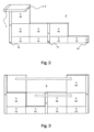
- Figure 2 shows a further embodiment of a system 1 according to the invention, which is similar to that in Figure 1 is constructed, but has a planar arrangement of the air conditioning modules K on the wall adapted to the specific circumstances of the room in question.
- the system 1 according to the second embodiment also has an air conditioning module K which is arranged on the ceiling D of the room.
- a distributor module V is arranged along the ceiling D in order to supply the air conditioning module K on the ceiling D.
- the distribution modules V each have several couplings 14 in an area near the floor.
- These couplings K can be hydraulic couplings for connecting additional air conditioning modules K, which can be arranged in the room, for example. Heated and/or cooled furniture can also be connected to the couplings. Examples of such furniture are shown in the Figures 8 and 9 At least some of the Figure 2
- the couplings 14 shown can also be electrical sockets and/or suitable connections for controlling the system or system components. For example, USB connections can be provided for this purpose.
- other infrastructure connections such as Internet connections, telephone connections and/or other interfaces can also be provided.
- FIG. 3 A third embodiment of a system 1 according to the invention is shown in Figure 3 shown.
- the Figure 3 illustrates how the arrangement of the air conditioning modules K can be changed at a later date.
- two air conditioning modules K are moved from left to right along the wall and repositioned. This can be advantageous if wall surfaces are to be used differently.
- system 1 offers much greater flexibility in the use of space.
- the air conditioning modules K are attached to the wall W using wall hooks or rails (see also Figure 7 ).
- the air conditioning modules are connected to each other and to the distribution modules via detachable couplings, similar to those used for solar thermal elements, for example.
- System 1 is given additional stability by the vertically arranged distribution beams V.
- the vertical distribution beams are preferably firmly mounted on the wall W.
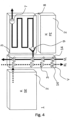
- FIG. 4 A section of a system 1 according to the invention is shown in Figure 4
- the modules are shown spaced apart from each other for a clearer presentation.
- Figure 4 shows a detailed section of a vertical distribution module V with a supply line VL (solid line) and a return line RL (dashed line) for a fluid carrier medium that transports heat and/or cold.
- the lines each have switchable three-way valves 3, by means of which the carrier medium flows into or out of the air conditioning modules.
- the three-way valves 3 can be used to control or switch a heat supply via the supply line VL to the heating circuits of the various air conditioning modules K.
- a meander-shaped line 8 is illustrated as the heating circuit of an air conditioning module K in the seat level. After a fluid carrier medium is supplied to the meander 8 via the supply line VL, the carrier medium gives off its heat to the surface 2 and flows back to a heating boiler via the return line RL.
- the meander 8 is connected to the surface 2 of the air conditioning module in a heat-conducting manner.
- a speed-controlled circulation pump 7 is arranged in the meander 8.
- the flow of the carrier medium through the air conditioning module K can be regulated via the speed of the pump 7.
- the pump 7 receives control signals from a control device for this purpose.
- the meander also has a check valve 9, which can prevent the carrier medium from flowing against the predetermined flow direction.
- the meander 8 of the air conditioning module K shown can be connected to an adjacent air conditioning module K (not shown) via suitable hydraulic couplings, so that several air conditioning modules K in the seating plane SE can be supplied by the distributor module V.
- the meander can be designed in such a way that it is fluidly connected to the return line RL of the distributor module in order to close the circuit directly.
- climate modules K behind or on the surface 2 can be integrated into additional functions such as loudspeakers, smoke detectors, C02 sensors, brightness sensors, humidity sensors, heat sensors and/or WiFi routers.
- additional functions such as loudspeakers, smoke detectors, C02 sensors, brightness sensors, humidity sensors, heat sensors and/or WiFi routers can be integrated into the climate modules K behind or on the surface 2.
- other infrastructures such as network cables, can be laid in the distribution elements V.
- Light switches for example, can also be arranged in the distribution elements V.
- FIG. 5 shows a distribution module V with a fresh air supply line FL and an exhaust air line AL.
- the air conditioning modules K can be supplied with fresh air via the fresh air supply line FL. Air that is sucked in via openings 6 in an air conditioning module can be discharged via the exhaust air line.
- the air conditioning modules K of the The embodiment can thus realize an active air exchange of the room air.
- the fresh air can be released into the room via the openings 6 in the surface 2.
- the inflow or outflow of air can be switched via three-way valves 3 in the exhaust air line AL and the fresh air line FL in the distributor module V.
- fans 7 are arranged in the exhaust air line AL and the fresh air line FL, which create an air flow.
- the ventilation lines in the air conditioning module K can be arranged in such a way that the outflowing fresh air exits along a meander 8 of a heating and/or cooling circuit running in the air conditioning module, so that a heat exchange can take place between the carrier medium flowing in the meander 8 and the fresh air.
- fans can also be arranged in the air conditioning modules in order to bring about a circulating air flow or an air flow of the room air around the heating and/or cooling circuits, so that an improved heat exchange can be brought about between the carrier medium and the room air.
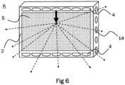
- Fig. 6 shows an embodiment of a climate module K for a system 1 according to the invention, which has a plurality of lighting means 4 for illuminating a room, which are arranged on two edge regions of the surface 2.
- the surface 2 of the climate module K has a plurality of scattering centers 5, which are introduced into the surface 2 by microstructuring processes.
- the surface is made, for example, from an aluminum sheet that has been processed by etching processes in order to produce the plurality of scattering centers 5.
- the thick arrow illustrates a light beam emitted by a light source 4 that is scattered homogeneously in the room by the multitude of scattering centers 5 (dashed arrows).
- the light sources 4 each have red, blue, green and white LEDs.
- the light emitted by the LEDs is directed by reflectors onto the surface 2 of the climate module K.
- a suitable lens combination in the light sources 4 ensures homogeneous illumination of the surface 2.
- Control electronics for example in the control device, controls the multitude of light sources 4 in order to control, for example, a color gradient, color change, brightness and other parameters of the light sources 4.
- the light sources 4 are thermally insulated from the surface 2 of the climate module. This can improve the service life of the light sources 4.
- the air conditioning module K also has a plurality of couplings 14 on its side, via which heating and/or cooling circuits in the air conditioning module K can be fluidly connected to hydraulic lines in a supply module.
- FIG 7 shows a side view of an exemplary climate module K for a system 1 according to the invention.
- a plurality of scattering centers 5 for scattering light are arranged on a metal surface 2 of the climate module K (see also Figure 6 ).
- a rear side of the air conditioning module K has a thermal insulation 12. This allows the air conditioning module K to be thermally insulated from the wall W, so that heat exchange with the wall W can be reduced and heat radiation into the room can be improved.
- Wall hooks 10 are arranged in the wall W and communicate with corresponding fastening eyes 11 in the air conditioning module K, so that a detachable fastening of the air conditioning module K to the wall W can be achieved.
- the housing of the K climate module should have the best possible thermal conductivity while being as lightweight as possible.
- composite materials can also be used.
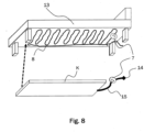
- Figure 8 shows a heated and/or coolable bed 13, which does not fall under the claims but implements partial aspects of the climate modules.
- the bed has a meandering heating and/or cooling circuit 8 arranged on the underside of the bed 13.
- a flow of a fluid carrier medium can be regulated via a speed-controlled pump 7 in the heating and/or cooling circuit 8.
- an air conditioning module 8 can also be arranged under the bed 13.
- the air conditioning module K has a supply line 15 with a speed-controlled pump 7.
- the supply line 15 can be fluidly connected to a coupling 14 in a distributor module via a suitable hydraulic coupling 14.
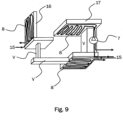
- FIG. 9 Another heated and/or cooled piece of furniture, which does not fall under the requirements but implements aspects of the climate modules, is shown in the Figure 9 .
- a workstation with a chair 16 and a table 17 is shown.
- the table 17 and the chair 16 have, similar to the bed 13 from Figure 8 , heating and/or cooling circuits 8, which can be supplied with the hydraulic carrier medium via suitable supply lines 15.
- the individual heating and/or cooling circuits 8 can either be connected separately to distribution modules V or connected in series with one another via distribution modules V integrated in the furniture.
- a pump 7 in the heatable and/or coolable workstation 16, 17 regulates the flow of the carrier medium.
Landscapes
- Engineering & Computer Science (AREA)
- Chemical & Material Sciences (AREA)
- Combustion & Propulsion (AREA)
- Mechanical Engineering (AREA)
- General Engineering & Computer Science (AREA)
- Physics & Mathematics (AREA)
- Sustainable Development (AREA)
- Life Sciences & Earth Sciences (AREA)
- Thermal Sciences (AREA)
- General Physics & Mathematics (AREA)
- Optics & Photonics (AREA)
- Devices For Blowing Cold Air, Devices For Blowing Warm Air, And Means For Preventing Water Condensation In Air Conditioning Units (AREA)
- Central Air Conditioning (AREA)
Description
- Die vorliegende Erfindung betrifft ein System zum Beleuchten und zum Heizen und/oder Kühlen und/oder Belüften eines Raumes.
- Die Gebrauchsmusterschrift
DE 20 2010 006 457 U1 offenbart einen Heizkörper mit einem Strahlelement, in dem eine Heizflüssigkeit zirkuliert, und einer mit dem Strahlelement verbundenen Abdeckung, die eine Beleuchtungsanordnung mit mindestens einer Lichtquelle umfasst. Die Abdeckung kann eine geformte Platte aus durchsichtigem Material, zum Beispiel PMMA, umfassen. - Aus der europäischen Patentanmeldung
EP 2 103 881 A2 ist ein Klimatisierungssystem für Räume bekannt, das aus mehreren Kassetten für Kassettenwände oder -decken besteht. Jede Kassette weist ein Klimatisierungsmodul mit einem Luftverteiler und einen von einem Fluid durchströmten Wärmetauscher auf, so dass im Betrieb des Klimatisierungsmoduls ein Wärmeaustausch zwischen dem durch den Wärmetauscher fließenden Fluid und der durch den Luftverteiler strömenden Luft stattfindet. Eine Steuereinrichtung regelt die Zufuhr von Luft und Fluid. - Die Gebrauchsmusterschrift
DE 20 2008 003 864 U1 betrifft ein Klimatisierungssystem für Räume und ein in Kassetten einer Kassettenwand oder -decke integriertes Klimatisierungsmodul. Dabei umfasst jedes Klimatisierungsmodul einen Luftverteiler und einen von einem Fluid durchströmten Wärmetauscher. Der Wärmetauscher und der Luftverteiler sind in dem Klimatisierungsmodul derart zueinander angeordnet, dass im Betrieb des Klimatisierungsmoduls ein Wärmeaustausch zwischen durch den Luftverteiler strömender Luft und einem durch den Wärmetauscher strömenden Fluid stattfindet. - Die internationale Patentanmeldung
WO 2012/126 524 A1 beschreibt ein modular aufgebautes System für den Innenraum eines Raums. Die Module können nebeneinander montiert werden, so dass eine zusammenhänge Oberfläche entsteht. - Die deutsche Patentanmeldung
DE 103 36 593 A1 offenbart ein Belüftungssystem für ein Kraftfahrzeug. - Die Druckschrift
EP 2 412 521 A1 offenbart einen beleuchteten Heizkörper aus Glas mit Leuchtfeldern, die in eine Verbundglasscheibe eingekoppeltes Licht nach außen reflektieren, emittieren oder streuen. - Der vorliegenden Erfindung liegt die Aufgabe zugrunde, ein gegenüber dem Stand der Technik verbessertes System zum Heizen und/oder Kühlen und/oder Lüften und/oder Beleuchten eines Raumes bereitzustellen. Insbesondere soll ein derartiges System bereitgestellt werden, das aus einzelnen genormten Modulen besteht, deren Anordnung an einer Wand und/oder einer Decke und/oder einem Boden eines Raumes besonderes flexibel ist und nachträglich verändert werden kann.
- Die Lösung der Aufgabe gelingt durch ein System nach Anspruch 1
Erfindungsgemäß weist die Oberfläche des Klimamoduls eine Vielzahl von Streuzentren zum Streuen von Licht auf, wobei das Licht von Leuchtmitteln emittiert wird, die an den Randbereichen der Oberfläche oder mittig auf der Oberfläche angeordnet sind. - Die Klimamodule weisen jeweils eine ebene, dem Raum zugewandte Oberfläche auf, über die eine Wärmeübertragung mit der Raumluft stattfinden kann, so dass Wärme und/oder Kälte an den Raum abgegeben werden kann. Der Wärmeübertrag kann auch über Strahlung erfolgen.
- Das erfindungsgemäße System kann nachträglich vor einer Wand aufgebaut werden, ohne dass Infrastrukturelemente, wie zum Beispiel hydraulische Leitungen oder Lüftungsleitungen, in der Wand vorhanden sein müssen beziehungsweise nachträglich eingebaut werden müssen. Das System kann parallel zu und vor einer Oberfläche einer Wand, einer Decke oder eines Bodens aufgebaut werden. Dabei bilden die Oberflächen der einzelnen Module eine im Wesentlichen zusammenhängende Oberfläche, die nicht nur für den Wärmeaustausch mit der Innenluft des Raumes sorgt, sondern auch optisch ansprechend und dekorativ sein kann.
- Auch in den Fällen wenn in der vorliegenden Beschreibung jeweils nur von "einer Wand" oder "der Wand" eines Raumes die Rede ist, versteht es sich, dass die betreffende Aussage auch für Anwendungen an einer Decke oder auf einem Boden eines Raumes zutrifft.
- Da die Klimamodule vor einer Wand aufgebaut und nicht in eine Wand eingebaut werden, können sie nachträglich und ohne großen Bauaufwand auch in Altbauten eingebaut werden. Zudem ist es möglich, die Anordnung der Klimamodule nachträglich zu ändern oder zu erweitern. Die Klimamodule können vorzugsweise lösbar an der Wand befestigt werden, damit die Anordnung der Klimamodule verändert werden kann.
- Das erfindungsgemäße System umfasst eine Vielzahl von Klimamodulen, die an einer Wand des Raumes angeordnet werden können. Die Klimamodule können eine genormte Größe aufweisen, so dass sie einfach kombinierbar sind, um einen Teil, insbesondere einen Großteil der Wand damit abzudecken. Alternativ oder zusätzlich können Klimamodule auch auf dem Boden und/oder an der Decke des Raumes angeordnet werden.
- Die Kontur der Klimamodule ist derart ausgebildet, dass sich durch Zusammensetzen mehrerer Klimamodule eine im Wesentlichen geschlossene Oberfläche bilden lässt. Hierzu sind beispielsweise eine rechteckige, dreieckige oder hexagonale Form oder auch eine Rautenform geeignet. Auch eine Kombination aus verschiedenen geometrischen Formen, ist möglich. Für die Herstellung und aufgrund der Tatsache, dass die meisten Innenräume von Gebäuden rechteckige Wände, Böden und Decken haben, ist es zweckmäßig, eine genormte rechteckige Form für die Klimamodule zu wählen.
- Das erfindungsgemäße System weist mindestens ein Verteilermodul auf, das dafür ausgelegt ist, der Vielzahl von Klimamodulen ein fluides Trägermedium für Wärme und/oder Kälte bereitzustellen. Ferner kann mindestens ein Verteilermodul dazu ausgelegt sein, Frischluft an mindestens ein Klimamodul bereitzustellen. Dazu können in den Verteilermodulen hydraulische Leitungen für das fluide Trägermedium angeordnet sein, die als Vorlauf zu und als Rücklauf von den Klimamodulen dienen. Die Verteilermodule umfassen somit die Infrastrukturelemente, welche üblicherweise unter Putz in Wänden, Decken und/oder Böden verlegt werden.
- Die Verteilermodule erlauben es, das erfindungsgemäße System so aufzubauen, dass eine Länge eines Vorlaufs beziehungsweise eine Länge eines Rücklaufs zwischen jedem der Vielzahl von Klimamodulen und einem Energieversorger im Wesentlichen gleich lang ist, so dass ein Strömungswiderstand des fluiden Trägermediums und/oder der Frischluft und/oder Abluft für jedes Klimamodul im Wesentlichen gleich groß ist.
- Bei herkömmlichen Heizungs-, Klima- und/oder Lüftungsanlagen kann es vorkommen, dass ein Trägermedium auf dem Weg vom Heizkessel zu den einzelnen Heizkörpern sehr unterschiedliche Strömungswiderstände überwinden muss, wodurch der Volumenstrom durch die verschiedenen Heizkörper stark variieren kann. Hierdurch kann das Problem auftreten, dass einzelne Heizkörper nicht ausreichend mit Wärme versorgt werden können.
- Um die Strömungswiderstände in einem herkömmlichen Heizungssystem auszugleichen, können aufwendige Berechnungen und/oder Messungen notwendig sein. Im Allgemeinen ist der Planungsaufwand sehr groß, wenn eine Unterversorgung einzelner Heizkörper vermieden werden soll.
- In den erfindungsgemäßen Verteilermodulen kann die komplette Versorgungsinfrastruktur integriert werden. Durch eine vertikale Anordnung der Verteilermodule an der Wand kann erreicht werden, dass der Strömungswiderstand für jedes Klimamodul innerhalb eines tolerierbaren Bereichs liegt, ohne dass aufwändige Planung und/oder Berechnung notwendig ist. Bei einer solchen Anordnung kann ein Verteilermodul eine Vielzahl von Klimamodulen, die auf beiden Seiten des Verteilermoduls an der Wand angeordnet sind, mit dem fluiden Trägermedium, Frischluft und/oder elektrischem Strom versorgen und/oder entsprechende Rücklaufleitungen bereitstellen.
- Die Vorlauf- und Rücklaufleitungen in den Verteilermodulen gehören zum sogenannten Primärkreis. Die Leitungen in den Klimamodulen gehören zum sogenannten Sekundärkreis. Die Verteilermodule sind so aufgebaut, dass sie die Leitungen des Primärkreises in einer möglichst einheitlichen Länge, und somit einem einheitlichen Strömungswiderstand, bereitstellen. Die hydraulischen Leitungen des Sekundärkreises können durch die Verwendung der Klimamodule ebenfalls einen einheitlichen Strömungswiderstand aufweisen.
- Bei dem fluiden Trägermedium kann es sich um eine Flüssigkeit oder ein Gas handeln, das vorzugsweise eine hohe Wärmekapazität besitzt. Beispiele für ein flüssiges Trägermedium umfassen Wasser, das aufgrund seiner hohen spezifischen Wärmekapazität und guten Verfügbarkeit besonders gut geeignet ist, Salz-Wasser-Lösungen, Alkohol-Wasser-Lösungen oder Öle sowie in besonderen Anwendungen auch Salzschmelzen oder flüssige Metalle. Das Trägermedium kann auch ein Gas oder Gasgemisch (z.B. Luft) sein. Insbesondere könnte vorgewärmte oder abgekühlte Luft zum Lüften und Heizen oder Kühlen des Raumes verwendet werden.
- Die Oberfläche der Klimamodule besteht vorzugsweise aus einem Material, dessen Wärmeleitkoeffizient möglichst hoch ist, so dass ein optimaler Wärmeaustausch mit der Luft des Raumes stattfinden kann. Beispielsweise kann die Oberfläche aus einem Metall, einer Metalllegierung, zum Beispiel Aluminium, einer Aluminiumlegierung, Stahl, Edelstahl, Messing oder Kupfer bestehen. Abgesehen von der guten Wärmeleitfähigkeit sind Metalle auch sehr gut formbar. Eine möglichst ebene Oberfläche kann somit unter Verwendung bekannter Fertigungstechniken hergestellt werden. Vorzugsweise ist die Oberfläche aus einem einstückigen Metallblech gefertigt. Ein weiterer Vorteil einer Metalloberfläche ist, dass sich darin auf einfache Weise Öffnungen für eine Lüftung einbringen lassen. Metallbleche werden auch bei herkömmlichen Heizkörpern vielseitig verwendet und weisen eine Vielzahl von Vorteilen auf.
- Die Oberfläche kann eine Vielzahl von Öffnungen, zum Beispiel eine Vielzahl kleiner Löcher aufweisen, um Frischluft zum Lüften des Raumes an den Raum abzugeben. Alternativ oder zusätzlich können die Öffnungen auch dazu dienen Luft aus dem Raum abzuführen, so dass die Klimamodule auch eine Funktion als Abzug ausführen können. Die Öffnungen können dementsprechend Lufteinlässe und/oder Luftauslässe sein. Die Klimamodule können somit für einen aktiven Luftaustausch in einem Raum sorgen, wobei die Temperatur der Raumluft konstant bleiben kann. Ferner können die Klimamodule dazu ausgelegt sein, eine Umluftfunktion bereitzustellen, so dass ein Wärmeaustausch zwischen Raumluft und den Heiz- und/oder Kühlkreisen verbessert werden kann, wobei kein aktiver Luftaustausch stattfinden muss.
- Die Klimamodule weisen hydraulische Heizkreise und/oder Kühlkreise und/oder Lüftungskanäle auf, wobei die Lüftungskanäle mit der Vielzahl von Öffnungen strömungsverbunden sind. Die Heizkreise und/oder Kühlkreise sind mit der raumzugewandten Oberfläche der Klimamodule in Wärmekontakt, so dass ein Wärmeübertrag zwischen dem Trägermedium und der Oberfläche stattfinden kann. Die Heizkreise und/oder Kühlkreise können zum Beispiel mäanderförmig entlang der Oberfläche angeordnet sein. Hiermit kann ein besonders guter Wärmeübertrag zwischen Trägermedium und Oberfläche des Klimamoduls erreicht werden.
- Das System umfasst eine Steuereinrichtung, welche dafür ausgelegt ist, eine zugeführte Wärmemenge und/oder Kältemenge und/oder Frischluftmenge und/oder Abluftmenge von und/oder zu den Klimamodulen zu steuern. Die Menge kann beispielsweise über die Regelung eines Flusses gesteuert werden. Ein Fluss bezeichnet im Folgenden allgemein einen Flüssigkeits-, Luft-, Gas- und/oder elektrischen Strom. Insbesondere kann die Steuereinrichtung fernsteuerbar sein. Die Steuereinrichtung kann dafür ausgelegt sein, zum Steuern des Systems Steuerbefehle an die Verteilermodule zu senden.
- Die Steuereinrichtung ermöglicht eine koordinierte Steuerung der Klimamodule über die Verteilermodule. Die Sekundärkreise des Systems können vorzugsweise über die Steuereinrichtung automatisch geregelt werden und dabei in einem optimalen Zustand betrieben werden. Somit kann das System besonders effizient betrieben werden. Durch eine Kombination der Steuereinrichtung mit moderner Kommunikationstechnik kann zudem eine Fernsteuerung des Systems bewirkt werden, die beispielsweise über das Internet, insbesondere auch unter Verwendung einer Steueranwendung auf einem mobilen Endgerät, erfolgen kann.
- Die Verteilermodule können hydraulische Kupplungen aufweisen, über die eine lösbare Verbindung zu Klimaelementen hergestellt werden kann, um die Klimaelemente mit dem fluiden Trägermedium für Wärme und/oder Kälte und/oder Frischluft zu versorgen. Die hydraulischen Kupplungen können jeweils mit Vorlaufleitungen und/oder Rücklaufleitungen in den Verteilermodulen in Strömungsverbindung stehen.
- Vorzugsweise können über die hydraulischen Kupplungen im Raum stehende beheizbare und/oder kühlbare Möbel (zum Beispiel eine Couch, ein Tisch oder ein Bett) angeschlossen werden. Dadurch können vom Nutzer bestimmte Raumbereiche (zum Beispiel ein Arbeitsplatz, eine Dusche, eine Couch oder ein Bett) gezielt mit beheizt oder auch gekühlt werden. Außerdem können vorprogrammierbare, tageszeitenabhängige Heizszenarien realisiert werden.
- Die Kupplungen können eine veränderbare und/oder erweiterbare Anordnung der Klimamodule an der Wand und/oder an der Decke und/oder am Boden ermöglichen. Die Verteilermodule können Leitungen für das fluide Trägermedium, beispielsweise Wasserleitungen, aufweisen. Wenn das Trägermedium zum Heizen und Kühlen des Raumes geeignet ist, dann können jeweils eine Vorlaufleitung und eine Rücklaufleitung ausreichend sein. Wird aber zum Heizen und Kühlen jeweils ein unterschiedliches Trägermedium verwendet, so kann das Verteilermodul jeweils getrennte Vorlaufleitungen und Rücklaufleitungen aufweisen.
- Zusätzlich zu den hydraulischen Kupplungen können die Verteilermodule auch Steckdosen für elektrischen Strom aufweisen, die mit elektrischen Leitungen in den Verteilermodulen verbunden sind. Die Steckdosen können über die Steuereinrichtung regelbar beziehungsweise schaltbar sein.
- Ferner können die Verteilermodule Frischluftleitungen und/oder Abluftleitungen aufweisen. Außerdem können in den Verteilermodulen Stromleitungen integriert sein. Für alle Leitungen können die Verteilermodule Schnittstellen (Kupplungen) aufweisen, über die die Klimamodule und/oder weitere anschließbare Möbel und/oder andere Vorrichtungen über entsprechende passende Gegenschnittstellen (Kupplungen) mit dem fluiden Trägermedium, Frischluft und/oder Strom versorgt werden können. Die Kupplungen können zum Beispiel mit einem Bajonettverschluss oder als Steckkupplungen mit passenden (abgedichteten) Stutzen ausgeführt sein, um ein schnelles und sicheres Verbinden zu ermöglichen.
- Um einen Fluss durch die Vorlaufleitungen beziehungsweise Rücklaufleitungen zu regeln, weisen die Klimamodule Ventile auf. Die Ventile werden durch die Steuereinrichtung geregelt.
- Die Ventile können schaltbar sein, so dass sie einen Fluss zulassen (Ein-Stellung) oder verhindern (Aus-Stellung) oder sie können einen Strom in einer Vielzahl von Stufen oder auch stufenlos Regeln. Die Ventile können beispielsweise Proportionalventile sein. Insbesondere können die Ventile als schaltbare Drei-Wege-Ventile ausgeführt sein. Jedes Drei-Wege-Ventil kann separat schaltbar sein. Über die Drei-Wege-Ventile können einzelne Klimamodule beziehungsweise einzelne Leitungen in einem Klimamodul mit einem Fluss versorgt werden.
- Zusätzlich zu den Ventilen können die Verteilermodule und/oder die Klimamodule Einrichtungen zum Regeln eines Flusses des fluiden Trägermediums und/oder zum Regeln eines Flusses der Frischluft durch das Verteilermodul aufweisen. Eine solche Einrichtung kann beispielsweise als drehzahlregulierte Umwälzpumpe ausgeführt sein, die beispielsweise über die Steuereinrichtung regelbar sein kann. Vorzugsweise weisen alle Klimamodule separat regelbare Umwälzpumpen in den Heiz- und/oder Kühlkreisläufen auf, wobei eine Zufuhr des Trägermediums über die Vorlauf- und/oder Rücklaufleitungen von den Verteilermodulen über schaltbare Dreiwege-Ventile geregelt wird.
- Die Klimamodule und/oder die Verteilermodule können jeweils separat regelbare Gebläsepumpen beziehungsweise Ventilatoren aufweisen. Hierdurch kann eine zugeführte Frischluftmenge und/oder eine abgeführte Abluftmenge geregelt werden. Alternativ können die Gebläsepumpen oder Ventilatoren dafür ausgelegt sein einen Umluftstrom bereitzustellen, der für einen verbesserten Wärmeaustausch zwischen Raumluft und Klimamodul sorgt, ohne einen aktiven Austausch der Raumluft zu bewirken.
- Zusätzlich können die Verteilermodule und/oder die Klimamodule Rückschlagventile (beziehungsweise Dioden zum Vorgeben einer Richtung des elektrischen Stroms) aufweisen, um dem Fluss des fluiden Trägermediums und/oder dem Luftstrom eine bestimmte Fließrichtung vorzugeben.
- Die Steuereinrichtung ist dafür ausgelegt, die Wärmemenge und/oder Kältemenge und/oder Frischluftmenge und/oder Abluftmenge für jedes Klimamodul separat zu regeln. So kann je nach Bedarf für ein bestimmtes Klimamodul eine individuell regelbare Wärmemenge und/oder Kältemenge und/oder Frischluftmenge eingestellt werden.
- Das erfindungsgemäße System kann raumweise und auch nachträglich und/oder parallel zu bereits bestehenden Heizsystemen oder Klimaanlagen aufgebaut und betrieben werden. Ein weiterer Vorteil gegenüber konventionellen Unterputz-Wandheizsystemen besteht darin, dass das erfindungsgemäße System vor der Wand (beziehungsweise unter der Decke und/oder über dem Boden) umgebaut und oder umarrangiert werden kann. Somit wird ermöglicht, dass das System auf eine geänderte Raum- und/oder Wandnutzung vom Anwender angepasst werden kann. Hierzu können die Klimamodule ohne Unterputzarbeiten an den Wänden und/oder an der Decke und/oder am Boden neu platziert, entfernt und/oder hinzugefügt werden. Hierzu können an der Wand spezielle Befestigungsmittel, beispielsweise in Form von Schienen, angebracht werden, an denen die Klimamodule lösbar befestigt werden können.
- Der modulare Aufbau des Systems mit vorgefertigten Klimamodulen kann Planung, Berechnung und Montage beim Einbauen eines solchen Systems, insbesondere auch bei einem nachträglichen Einbau und/oder einer Bestandssanierung, vereinfachen. Im Falle eines Neubaus, insbesondere mit fertig vorgefertigten Wandelementen, kann das System bereits vor der Endmontage eingebaut werden. Dadurch kann eine höhere Fertigungstiefe beim Haushersteller erzielt werden, wodurch auch eine Zeit- und Kostenreduzierung bei der Heizungsendmontage durch Handwerker auf der Baustelle erreicht werden kann.
- Das System kann ferner dazu ausgelegt sein, innerhalb eines Raumes mindestens drei Klimazonen bereitzustellen, in denen eine jeweils unabhängig voneinander einstellbare Wärmemenge und/oder Kältemenge und/oder Frischluftmenge bereitgestellt wird. Die drei Klimazonen können beispielsweise nach einer Höhe im Raum eingestellt werden. So kann etwa eine Fußebene, eine Sitzebene und eine Kopfebene unabhängig voneinander geregelt werden. Eine solche Einteilung in Klimazonen nach Ebenen kann insbesondere deshalb vorteilhaft sein, da warme Luft nach oben zur Decke des Raumes steigt und kalte Luft nach unten zum Boden des Raumes absinkt. Durch das Einstellen der Klimazonen, kann eine gleichmäßigere Verteilung der Wärme in einem Raum erreicht werden. Ferner kann die Einteilung in Zonen auf die Gegebenheiten im Raum angepasst sein. Bereiche, an denen sich Personen im Raum besonders häufig aufhalten können bevorzugt mit Wärme und/oder Kälte und/oder Frischluft versorgt werden.
- Die Oberfläche der Klimamodule weist eine Vielzahl von Streuzentren auf. Die Streuzentren dienen zum Streuen von Licht, das von Leuchtmitteln emittiert wird, die an einem Randbereich der Oberfläche des Klimamoduls angeordnet sein können und die Oberfläche möglichst homogen ausleuchten. Alternativ oder zusätzlich können die Leuchtmittel auch mittig auf der Oberfläche angeordnet sein und ihr Licht radial nach außen abgeben und dabei die Oberfläche des Klimamoduls möglichst homogen ausleuchten.
- Die Streuzentren können im einfachsten Fall als Oberflächenrauheit durch eine geeignete Oberflächenbehandlung hergestellt werden. Erfindungsgemäß sind die Streuzentren als Mikrostrukturen in oder auf der Oberfläche ausgebildet, die ein diffuses Streuen des von den Leuchtmitteln emittierten Lichts in den Raum hinein bewirken. Die Streuzentren sind Mikroprismen, Mikroprismen-Arrays, Mikrolinsen und/oder Mikrolinsen-Arrays. Die Streuzentren können auf einem Teil oder auf der gesamten Oberfläche des Klimamoduls angeordnet sein. Die Streuzentren können entweder direkt in der Oberfläche eingearbeitet sein, als dünne Folie aufgeklebt sein oder auch auf der Oberfläche aufgedampft sein. Die reflektierende Mikrostruktur auf der Oberfläche des Heizflächensystems kann schrägwinklig und gebündeltes auf die Struktur einfallendes Licht homogen streuen und in den Raum projizieren.
- Ein direktes Einarbeiten der Streuzentren in das Material der Oberfläche, beispielsweise durch Ätzverfahren, Erodierverfahren, Laserbearbeitung oder andere geeignete Oberflächenbearbeitung. hat den Vorteil, dass hierdurch eine Wärmeleitfähigkeit der Oberfläche nicht beeinträchtigt wird. Dies ermöglicht es, dass dieselbe Oberfläche zum Streuen von (sichtbarem) Licht und zum Wärmeübertrag, auch durch Abstrahlung von Wärmestrahlung, nutzbar gemacht wird. Insbesondere kann hierdurch der Einsatz von schlechten Wärmeleitern wie Plexiglas- und/oder Acrylglas-Elementen gänzlich vermieden werden.
- Die Leuchtmittel bestehen vorzugsweise aus einer Vielzahl von Leuchtdioden, die beispielsweise rotes und/oder blaues und/oder grünes (RGB) und/oder weißes und/oder Schwarz- (UV) Licht abgeben können. Weißes Licht kann auch durch Mischen von rotem, blauen und grünem Licht erzeugt werden. Bei Verwendung von Leuchtdioden in rot, blau und grün (RGB) können mittels Farbmischung beliebige Farbtöne im gesamten Farbspektrum erzielt werden.
- Die Leuchtmittel sind vorzugsweise wasserdicht versiegelt, so dass sie auch für den Einsatz in Nassräumen, wie zum Beispiel in einem Badezimmer, geeignet sind. Die Leuchtmittel sind in vorteilhafter Weise durch konstruktive Maßnahmen thermisch von der Oberfläche entkoppelt. Insbesondere wenn die Oberfläche zum Heizen verwendet wird kann hierdurch die Lebensdauer der Leuchtmittel erhöht werden. Die (Infrarot-) Wärmeabstrahlung der Oberfläche der Klimamodule wird durch diese Konstruktion nicht behindert, sondern kann hierdurch optimiert werden.
- Die Beleuchtung eines Klimamoduls kann dazu ausgelegt sein, den jeweiligen Zustand des Moduls optisch anzuzeigen. So kann das Klimamodul beispielsweise Rottöne zum Anzeigen eines Heizzustands und/oder Blautöne zum Anzeigen eines Kühlzustands verwenden. Durch eine frei regelbare RGB-Farbmischung kann auch eine indirekte Raumbeleuchtung in nahezu beliebig wählbaren Farben erzielt werden. An der Decke angeordnete Klimamodule können auch Leuchtmittel umfassen, die weißes Licht abgeben und eine homogene Raumbeleuchtung bewirken.
- Ferner können die Leuchtmittel auch derart angesteuert werden, dass Farbverläufe auf den Oberflächen der Klimamodule darstellbar sind. Die Farbverläufe können sich auch über mehrere Klimamodule in koordinierter Weise erstrecken. Dazu kann die Steuereinrichtung erkennen wie viele Klimamodule in welcher Anordnung an Wänden, Decke und/oder Boden angebracht sind. Alternativ kann die Anordnung der Klimamodule konfiguriert werden. Beispielsweise können der Natur nachempfundene Farbverläufe an den Wänden und/oder an der Decke abgebildet werden. Im abendlichen Heizbetrieb können zum Beispiel gedämpfte Rottöne, die einem Sonnenuntergang nachempfunden sind, angezeigt werden. Am Morgen können zum Beispiel helle Blau-Weiß-Kombinationen als Lichtdusche dargestellt werden. In einem Arbeitsbereich kann eine möglichst gleichmäßige helle Ausleuchtung bereitgestellt werden.
- Außerdem kann eine bewegungsaktivierte, gedimmte Nachtbeleuchtung in der Fußzone realisiert werden, die den Nutzer bei der Bewegung durchs Haus begleitet und dabei einen Weg in gedämpftem, zum Beispiel Schwarz-, Licht ausleuchtet.
- Die Leuchtmittel können ferner Prismen und/oder Linsen aufweisen, um das von ihnen emittierte Licht möglichst homogen auf die Oberfläche der Klimamodule zu lenken. Beispielsweise können die Prismen und/oder Linsen das Licht unter einem Winkel von weniger als 20 Grad auf die Streuzentren der Oberfläche ablenken.
- Ferner können Parabolreflektoren hinter den Leuchtmitteln angeordnet sein, um das Licht auf die Oberfläche der Klimamodule zu richten. Dabei kann eine Fokussierung beziehungsweise Kollimation des Lichtes erfolgen. Ferner können Fresnel-Linsen vor den Leuchtmitteln eine Lichtbündelung und eine gerichtete Projektion der Lichtstrahlen auf die Oberfläche der Klimamodule mit den Streuzentren bewirken. Die Leuchtmittel sind vorzugsweise durch eine entsprechende mechanische Konstruktion derart mit der Oberfläche verbunden, dass die beim Betrieb der Leuchtmittel entstehende Wärme effektiv abgeführt wird.
- Die Oberfläche der Klimamodule ist vorzugsweise aus einem Material mit einem Wärmeleitkoeffizienten von mindestens 50 W/(m K) gefertigt. Hierzu kann wie oben beschrieben vorzugsweise ein metallisches Material oder eine Metalllegierung verwendet werden. Besonders geeignet ist beispielsweise Aluminium mit einem Wärmeleitkoeffizienten von über 200 W/(m K).
- Weitere vorteilhafte Ausgestaltungen werden nachfolgend anhand eines in den Zeichnungen dargestellten Ausführungsbeispiels, das hilft Einzelheiten der Erfindung zu verstehen, näher beschrieben.
- Es zeigen schematisch:
- Figur 1
- eine Explosionsansicht eines Systems zum Heizen und Belüften eines Raumes mit zwölf Klimamodulen und drei Verteilermodulen zum Anordnen an einer Wand des Raumes.
- Figur 2
- ein System zum Heizen und Belüften eines Raumes mit acht Klimamodulen und drei Verteilermodulen.
- Figur 3
- ein System zum Heizen und Belüften eines Raumes mit acht Klimamodulen und drei Verteilermodulen.
- Figur 4
- eine Detailansicht, die einen Heizungskreislauf in einem Verteilermodul und einem Klimamodul illustriert.
- Figur 5
- eine Detailansicht, die einen Lüftungskreislauf in einem Verteilermodul und Klimamodulen illustriert.
- Figur 6
- ein Klimamodul mit Leuchtelementen und Streuzentren zum Beleuchten eines Raumes.
- Figur 7
- eine Seitenansicht eines Klimamoduls, die ein Befestigen des Klimamoduls an einer Wand illustriert.
- Figur 8
- ein beheizbares Bett.
- Figur 9
- einen beheizbaren Arbeitsplatz.
- Bei der nachfolgenden Beschreibung bezeichnen gleiche Bezugszeichen gleiche oder vergleichbare Komponenten.
-
Figur 1 zeigt ein Ausführungsbeispiel eines erfindungsgemäßen Systems 1 zum Heizen und Belüften eines Raumes mit zwölf Klimamodulen K und drei Verteilermodulen V ist zur besseren Übersicht in Explosionsdarstellung gezeichnet. Das Beispiel zeigt eine Anordnung, die eine Wand eines Raumes vollständig bedeckt. Hierzu weist das System 1 zwei Eck-Verteilermodule V auf und ein mittiges Verteilermodul V. Die Klimamodule K sind in drei Zonen aufgeteilt: eine Kopfebene KE, eine Sitzebene SE und eine Fußebene FE, die unabhängig voneinander geregelt werden können. In der Explosionsdarstellung sind die einzelnen Module voneinander beabstandet gezeichnet. In einem eingebauten Zustand binden die Module eine zusammenhängende Oberfläche. - An die Eck-Verteilermodule V können weitere Klimamodule K in rechtem Winkel zu den dargestellten Klimamodulen K angeschlossen werden, so dass die gesamte Innenwand eines Raumes komplett mit Klimamodulen ausgekleidet werden könnte. Für Räumen, die einen nicht-rechteckigen Grundriss aufweisen, können die Verteilermodule für die Raumecken auf die jeweiligen Gegebenheiten angepasst werden, so dass auch Winkel von weniger als 90 Grad beziehungsweise größer als 90 Grad abgedeckt werden können.
-
Figur 2 zeigt ein weiteres Ausführungsbeispiel eines erfindungsgemäßen Systems 1, das ähnlich wie jenes inFigur 1 aufgebaut ist, aber eine auf spezielle Begebenheiten des betreffenden Raumes angepasste flächige Anordnung der Klimamodule K an der Wand aufweist. Eine solche Anordnung kann beispielsweise bei Vorhandensein von Fenstern oder Möbeln oder einem Fernseher an der Wand oder bei einer Dachschräge vorteilhaft sein. Das System 1 gemäß dem zweiten Ausführungsbeispiel weist zudem ein Klimamodul K auf, das an der Decke D des Raumes angeordnet ist. Ein Verteilermodul V ist entlang der Decke D angeordnet, um das Klimamodul K an der Decke D zu versorgen. Ferner weisen die Verteilermodule V an einem Bereich in der Nähe des Bodens jeweils mehrere Kupplungen 14 auf. Diese Kupplungen K können hydraulische Kupplungen zum Anschließen weiterer Klimamodule K sein, die beispielsweise im Raum angeordnet werden können. An den Kupplungen können auch beheizbare und/oder kühlbare Möbel angeschlossen werden. Ausführungsbeispiele solcher Möbel sind in denFiguren 8 und9 dargestellt. Wenigstens einige der inFigur 2 gezeigten Kupplungen 14 können auch elektrische Steckdosen und/oder geeignete Anschlüsse zum Steuern des Systems oder von Systemkomponenten sein. Hierzu können beispielsweise USB-Anschlüsse bereitgestellt werden. Ferner können auch andere Infrastruktur-Anschlüsse, wie zum Beispiel Internet-Anschlüsse, Telefonanschlüsse und/oder andere Schnittstellen bereitgestellt werden. - Ein drittes Ausführungsbeispiel eines erfindungsgemäßen Systems 1 ist in
Figur 3 dargestellt. DieFigur 3 illustriert, wie eine nachträgliche Änderung der Anordnung der Klimamodule K erfolgen kann. Hier werden zwei Klimamodule K von links nach rechts entlang der Wand bewegt und neu platziert. Dies kann dann vorteilhaft sein, wenn Wandflächen anders genutzt werden sollen. Im Gegensatz zu fest in der Wand verbauten Flächenheizsystemen ist somit durch das System 1 eine viel höhere Flexibilität der Raumnutzung gegeben. - Die Befestigung der Klimamodule K an der Wand W erfolgt zum Beispiel mittels Wandhaken oder an Schienen (siehe auch
Figur 7 ). Untereinander und mit den Verteilermodulen verbunden sind die Klimamodule über lösbare Kupplungen wie sie beispielsweise in ähnlicher Weise auch bei Solarthermieelementen verwendet werden. Zusätzliche Stabilität erhält das System 1 durch die vertikal angeordneten Verteilerbalken V. Die vertikalen Verteilerbalken sind vorzugsweise fest an der Wand W montiert. - Ein Ausschnitt eines erfindungsgemäßen Systems 1 ist in
Figur 4 dargestellt. Lediglich für eine übersichtlichere Darstellung sind die Module beabstandet voneinander gezeichnet.Figur 4 zeigt einen Detailausschnitt eines vertikalen Verteilermoduls V mit einer Vorlaufleitung VL (durchgezogenen Linie) und einer Rücklaufleitung RL (gestrichelte Linie) für ein fluides Trägermedium, das Wärme und/oder Kälte transportiert. Die Leitungen weisen jeweils schaltbare Dreiwege-Ventile 3 auf, mittels derer ein Zufließen beziehungsweise Abfließen des Trägermediums in beziehungsweise aus den Klimamodulen erreicht wird. - Ferner sind drei Klimamodule K in
Figur 4 dargestellt. Über die Dreiwege-Ventile 3 kann eine über die Vorlaufleitung VL erfolgende Wärmezufuhr in die Heizkreise der verschiedenen Klimamodule K gesteuert beziehungsweise geschaltet werden. Beispielhaft illustriert wird als Heizkreis eines Klimamoduls K in der Sitzebene eine mäanderförmige Leitung 8. Nachdem ein fluides Trägermedium dem Mäander 8 über die Vorlaufleitung VL zugeführt wird, gibt das Trägermedium seine Wärme an die Oberfläche 2 ab und fließt über die Rücklaufleitung RL zurück zu einem Heizungskessel. Der Mäander 8 ist wärmeleitend mit der Oberfläche 2 des Klimamoduls verbunden. In dem Mäander 8 ist eine drehzahlsteuerbare Umwälzpumpe 7 angeordnet. Über die Drehzahl der Pumpe 7 kann ein Fluss des Trägermediums durch das Klimamodul K geregelt werden. Die Pumpe 7 empfängt hierzu Steuersignale von einer Steuereinrichtung. Ferner weist der Mäander ein Rückschlagventil 9 auf, welches ein Fließen des Trägermediums entgegen der vorgegebenen Fließrichtung verhindern kann. - Der dargestellt Mäander 8 des Klimamoduls K kann über geeignete hydraulische Kupplungen mit einem benachbarten Klimamodul K (nicht dargestellt) verbunden sein, so dass mehrere Klimamodule K in der Sitzebene SE durch das Verteilermodul V versorgt werden können. Alternativ kann der Mäander aber derart ausgeführt sein, dass er mit dem Rücklauf RL des Verteilermoduls strömungsverbunden ist, um den Kreislauf direkt zu schließen.
- Weiterführend können in die Klimamodule K hinter oder auch auf der Oberfläche 2 Zusatzfunktionen wie Lautsprecher, Rauchmelder, C02-Sensoren, Helligkeitssensoren, Luftfeuchtesensoren, Wärmesensoren und/oder W-LAN-Router integriert werden. Ferner können weitere Infrastrukturen, wie zum Beispiel Netzwerkkabel, in den Verteilerelementen V verlegt werden. Auch können zum Beispiel Lichtschalter in den Verteilerelementen V angeordnet werden.
- Ein weiterer Ausschnitt eines erfindungsgemäßen Systems 1 ist in
Figur 5 dargestellt. Lediglich für eine übersichtlichere Darstellung sind die Module beabstandet voneinander gezeichnet. DieFigur 5 zeigt ein Verteilermodul V mit einer Frischluftzuleitung FL und einer Abluftleitung AL. Über die Frischluftzuleitung FL können die Klimamodule K mit Frischluft versorgt werden. Durch die Abluftleitung kann Luft, die über Öffnungen 6 in einem Klimamodul angesaugt wird, abgeführt werden. Die Klimamodule K des Ausführungsbeispiels können somit einen aktiven Luftaustausch der Raumluft realisieren. Über die Öffnungen 6 in der Oberfläche 2 kann die Frischluft in den Raum abgegeben werden. Über Dreiwege-Ventile 3 in der AbluftleitungAL und der Frischluftleitung FL in dem Verteilermodul V kann ein Zufluss beziehungsweise Abfluss von Luft geschaltet werden. Außerdem sind in der Abluftleitung AL und der Frischluftleitung FL jeweils Ventilatoren 7 angeordnet, die einen Luftstrom bewirken. - Die Lüftungsleitungen im Klimamodul K können derart angeordnet sein, dass die ausströmende Frischluft entlang einem in dem Klimamodul verlaufenden Mäander 8 eines Heiz- und/oder Kühlkreises austritt, so dass ein Wärmeaustausch zwischen dem in dem Mäander 8 fließenden Trägermedium und der Frischluft erfolgen kann. Ferner können auch in den Klimamodulen Ventilatoren angeordnet sein, um einen Umluftstrom beziehungsweise einen Luftstrom der Raumluft um die Heiz- und/oder Kühlkreise zu bewirken, so dass ein verbesserter Wärmeaustausch zwischen dem Trägermedium und der Raumluft bewirkt werden kann.
-
Fig. 6 zeigt ein Ausführungsbeispiel eines Klimamoduls K für ein erfindungsgemäßes System 1, das zum Beleuchten eines Raumes eine Vielzahl von Leuchtmitteln 4 aufweist, die an zwei Randbereichen der Oberfläche 2 angeordnet sind. Die Oberfläche 2 des Klimamoduls K weist eine Vielzahl von Streuzentren 5 auf, die durch Mikrostruktur-Verfahren in die Oberfläche 2 eingebracht sind. Die Oberfläche ist beispielsweise aus einem Aluminium-Blech gefertigt, das durch Ätzverfahren bearbeitet wurde, um die Vielzahl von Streuzentren 5 zu erzeugen. - Beispielhaft illustriert der dicke Pfeil einen von einem Leuchtmittel 4 abgegebenen Lichtstrahl der von der Vielzahl von Streuzentren 5 homogen in den Raum gestreut wird (gestrichelte Pfeile). Die Leuchtmittel 4 weisen jeweils rote, blaue, grüne und weiße LEDs auf. Das von den LEDs emittierte Licht wird durch Reflektoren auf die Oberfläche 2 des Klimamoduls K gerichtet. Eine geeignete Linsenkombination in den Leuchtmitteln 4 sorgt für eine homogene Ausleuchtung der Oberfläche 2. Eine Steuerelektronik, zum Beispiel in der Steuereinrichtung, steuert die Vielzahl der Leuchtmittel 4, um beispielsweise einen Farbverlauf, Farbwechsel, Helligkeit und weitere Parameter der Leuchtmittel 4 zu steuern. Die Leuchtmittel 4 sind thermisch von der Oberfläche 2 des Klimamoduls isoliert. Hierdurch kann die Lebensdauer der Leuchtmittel 4 verbessert werden.
- Das Klimamodul K weist an seiner Seite außerdem eine Vielzahl von Kupplungen 14 auf, über die Heiz- und/oder Kühlkreisläufe in dem Klimamodul K mit hydraulischen Leitungen in einem Versorgungsmodul strömungsverbunden werden können.
-
Figur 7 zeigt eine Seitenansicht eines beispielhaften Klimamoduls K für ein erfindungsgemäßes System 1. Auf einer metallenen Oberfläche 2 des Klimamoduls K ist eine Vielzahl von Streuzentren 5 zum Streuen von Licht angeordnet (siehe auchFigur 6 ). Eine Rückseite des Klimamoduls K weist eine Thermoisolierung 12 auf. Hiermit kann das Klimamodul K thermisch gegenüber der Wand W isoliert werden, so dass ein Wärmeaustausch mit der Wand W vermindert und eine Wärmeabstrahlung in den Raum verbessert werden kann. - In der Wand W sind Wandhaken 10 angeordnet, die mit entsprechenden Befestigungsösen 11 in dem Klimamodul K kommunizieren, so dass eine lösbare Befestigung des Klimamoduls K an der Wand W bewirkt werden kann.
- Das Gehäuse des Klimamoduls K soll möglichst gut wärmeleitfähig bei einem möglichst geringen Gewicht sein. Neben Aluminium oder dünnem Stahlblech können dafür auch Verbundmaterialien zum Einsatz kommen.
-
Figur 8 zeigt ein beheizbares und/oder kühlbares Bett 13, das nicht unter die Ansprüche fällt aber Teilaspekte der Klimamodule implementiert. Das Bett weist hierfür einen an der Unterseite des Betts 13 angeordneten mäanderförmigen Heiz- und/oder Kühlkreislauf 8 auf. Über eine drehzahlgesteuerte Pumpe 7 im Heiz- und/oder Kühlkreislauf 8 kann ein Fluss eines fluiden Trägermediums geregelt werden. Alternativ zu dem am Bett 13 angeordneten Heiz- und/oder Kühlkreislauf 8 kann auch ein Klimamodul 8 unter dem Bett 13 angeordnet werden. Das Klimamodul K weist eine Zuleitung 15 mit einer drehzahlgesteuerten Pumpe 7 auf. Die Zuleitung 15 kann über eine geeignete hydraulische Kupplung 14 mit einer Kupplung 14 in einem Verteilermodul strömungsverbunden werden. - Ein weiteres beheizbares und/oder kühlbares Möbel, das nicht unter die Ansprüche fällt aber Teilaspekte der Klimamodule implementiert, zeigt die
Figur 9 . Hier ist ein Arbeitsplatz mit einem Stuhl 16 und einem Tisch 17 dargestellt. Der Tisch 17 und der Stuhl 16 weisen, ähnlich wie das Bett 13 ausFigur 8 , Heiz- und/oder Kühlkreisläufe 8 auf, die über geeignete Zuleitungen 15 mit dem hydraulischen Trägermedium versorgt werden können. - Die einzelnen Heiz- und/oder Kühlkreisläufe 8 können entweder jeweils separat mit Verteilermodulen V verbunden werden oder über in dem Möbel integrierte Verteilermodule V miteinander in Serie geschaltet sein. Eine Pumpe 7 in dem beheizbaren und/oder kühlbaren Arbeitsplatz 16, 17 regelt den Fluss des Trägermediums.
- Die Erfindung wird durch die Ansprüche definiert.
-
- 1
- System zum Heizen und/oder Kühlen und/oder Belüften und/oder Beleuchten
- 2
- Oberfläche
- 3
- Drei-Wege-Ventil
- 4
- Leuchtmittel
- 5
- Streuzentren
- 6
- Öffnungen
- 7
- Umwälzpumpe bzw. drehzahlgeregelter Lüfter
- 8
- Mäander
- 9
- Rückschlagventil
- 10
- Wandhaken
- 11
- Befestigungsöse
- 12
- Thermoisolierung
- 13
- Bett
- 14
- (Hydraulische) Kupplung
- 15
- Zuleitung
- 16
- Stuhl
- 17
- Tisch
- VL
- Vorlauf
- RL
- Rücklauf
- FL
- Frischluftzuleitung
- AL
- Abluftleitung
- K
- Klimamodul
- FE
- Fußebene
- SE
- Sitzebene
- KE
- Kopfebene
- W
- Wand
- D
- Decke
Claims (9)
- System (1) zum Beleuchten und zum Heizen und/oder Kühlen und/oder Belüften eines Raumes, umfassend:eine Vielzahl von Klimamodulen (K), wobei das Klimamodul (K) eine ebene Oberfläche (2) aufweist, die dafür ausgelegt ist, Licht und Wärme und/oder Kälte an den Raum abzugeben;mindestens ein Verteilermodul (V), das dafür ausgelegt ist, der Vielzahl von Klimamodulen (K) das fluide Trägermedium für Wärme und/oder Kälte und/oder Frischluft bereitzustellen; undeine Steuereinrichtung zum Steuern einer Wärmemenge und/oder Kältemenge und/oder Frischluftmenge, wobei:die Kontur der Vielzahl von Klimamodulen (K) und des mindestens einen Verteilermoduls (V) derart ausgebildet ist, dass die Vielzahl von Klimamodulen (K) und das mindestens eine Verteilermodul (V) durch Zusammensetzen eine im Wesentlichen ebene und zusammenhängende Oberfläche bilden; unddie Oberflächen (2) der Klimamodule (K) jeweils eine Vielzahl von Streuzentren (5) zum Streuen von Licht aufweisen, wobei das Licht von Leuchtmitteln (4) emittiert wird, die an einem Randbereich der Oberfläche (2) oder mittig auf der Oberfläche (2) angeordnet sind,wobeijedes Klimamodul (K) hydraulische Heizkreise und/oder Kühlkreise für ein fluides Trägermedium zum Bereitstellen von Wärme und/oder Kälte aufweist,jedes Klimamodul (K) separat über regelbare Ventile (3) mit mindestens einem Verteilermodul (V) verbunden ist und die Steuereinrichtung eingerichtet ist, jedes der regelbaren Ventile (3) separat zu regeln, so dass die Wärmemenge und/oder Kältemenge und/oder Frischluftmenge für jedes der Vielzahl von Klimamodulen (K) separat regelbar ist, wobei das mindestens eine Verteilermodul (V) die Vielzahl regelbarer Ventile (3) aufweist,die Heizkreise und/oder Kühlkreise mit der Oberfläche (2) der Klimamodule (K) in Wärmekontakt stehen für einen Wärmeübertrag zwischen dem fluiden Trägermedium und der Oberfläche (2), unddie Streuzentren (5) als Mikroprismen, Mikroprismen-Arrays, Mikrolinsen und/oder Mikrolinsen-Arrays in oder auf der Oberfläche (2) ausgebildet sind, die ein diffuses Streuen des von den Leuchtmitteln (4) emittierten Lichts in den Raum hinein bewirken.
- System (1) nach Anspruch 1, wobei die Oberflächen (2) der Klimamodule (K) jeweils eine Vielzahl von Öffnungen (6) zum Abgeben von Frischluft an den Raum aufweisen.
- System (1) nach Anspruch 1 oder 2, wobei jedes Klimamodul eine Einrichtung (7) zum Regeln eines Flusses des fluiden Trägermediums und/oder zum Regeln eines Flusses von Frischluft durch das Klimamodul (K) aufweist.
- System (1) nach mindestens einem der vorhergehenden Ansprüche, wobei die Klimamodule (K) dafür ausgelegt sind, lösbar an der mindestens einen Wand (W) und/oder Decke (D) und/oder am Boden des Raumes angeordnet zu werden, so dass die Anordnung der Klimamodule (K) veränderbar ist.
- System (1) nach mindestens einem der vorhergehenden Ansprüche, wobei das mindestens eine Verteilermodul (V) hydraulische Kupplungen (14) aufweist, über die eine lösbare Verbindung zu den Klimamodulen (K) und/oder hydraulischen Möbeln (14, 16, 17) hergestellt werden kann, um die Klimamodule (K) mit dem fluiden Trägermedium für Wärme und/oder Kälte und/oder Frischluft zu versorgen.
- System (1) nach Anspruch 1, wobei die Leuchtmittel (4) Leuchtdioden sind, die rotes und/oder blaues und/oder grünes und/oder weißes Licht abgeben.
- System (1) nach Anspruch 1 oder 6, wobei die Leuchtmittel (4) Prismen und/oder Linsen aufweisen, um das von ihnen emittierte Licht unter einem Winkel von weniger als 20 Grad zur Oberfläche (2) eines Klimamoduls (K) auf die Streuzentren (5) der Oberfläche (2) abzulenken.
- System (1) nach mindestens einem der vorhergehenden Ansprüche, wobei die Oberfläche (2) der Klimamodule (K) aus einem Material mit einem Wärmeleitkoeffizienten von mindestens 50 W/(m K) besteht.
- System (1) nach mindestens einem der vorhergehenden Ansprüche, wobei das mindestens eine Verteilermodul (V) mindestens eine Einrichtung (7) zum Regeln eines Flusses des fluiden Trägermediums und/oder zum Regeln eines Flusses der Frischluft durch das Verteilermodul (V) aufweist.
Applications Claiming Priority (2)
| Application Number | Priority Date | Filing Date | Title |
|---|---|---|---|
| DE102015225815.7A DE102015225815B4 (de) | 2015-12-17 | 2015-12-17 | Vorrichtung und System zum Heizen, Kühlen, Belüften und Beleuchten eines Innenraums |
| PCT/EP2016/081597 WO2017103220A2 (de) | 2015-12-17 | 2016-12-16 | System und vorrichtung zum heizen, kühlen, belüften und beleuchten eines innenraums |
Publications (3)
| Publication Number | Publication Date |
|---|---|
| EP3390919A2 EP3390919A2 (de) | 2018-10-24 |
| EP3390919B1 true EP3390919B1 (de) | 2024-11-20 |
| EP3390919C0 EP3390919C0 (de) | 2024-11-20 |
Family
ID=57777589
Family Applications (1)
| Application Number | Title | Priority Date | Filing Date |
|---|---|---|---|
| EP16825364.9A Active EP3390919B1 (de) | 2015-12-17 | 2016-12-16 | System und vorrichtung zum heizen, kühlen, belüften und beleuchten eines innenraums |
Country Status (5)
| Country | Link |
|---|---|
| US (1) | US10422538B2 (de) |
| EP (1) | EP3390919B1 (de) |
| CA (1) | CA3008717C (de) |
| DE (1) | DE102015225815B4 (de) |
| WO (1) | WO2017103220A2 (de) |
Families Citing this family (2)
| Publication number | Priority date | Publication date | Assignee | Title |
|---|---|---|---|---|
| DE102016223335A1 (de) | 2016-11-24 | 2018-05-24 | Viessmann Werke Gmbh & Co Kg | Flächenheizgewebe mit hydraulischen Heizrohren und Seitenlichtfasern |
| AT520083B1 (de) * | 2017-08-30 | 2019-01-15 | Harreither Gmbh | Klimamodul |
Family Cites Families (21)
| Publication number | Priority date | Publication date | Assignee | Title |
|---|---|---|---|---|
| US5151063A (en) * | 1989-10-03 | 1992-09-29 | Zexel Corporation | Air conditioning distribution system |
| JPH04316939A (ja) | 1991-04-12 | 1992-11-09 | Sharp Corp | 冷暖房機及びその制御方法 |
| DE10336593B4 (de) | 2003-08-08 | 2006-11-30 | Daimlerchrysler Ag | Klimaanlage für ein Kraftfahrzeug |
| CN2713355Y (zh) | 2004-04-06 | 2005-07-27 | 北京工业大学 | 可实现光催化空气净化与自然通风的光导管装置 |
| CN101365362B (zh) * | 2005-10-27 | 2010-10-13 | Ofi投资有限公司 | 工作台系统 |
| KR200433253Y1 (ko) * | 2006-09-15 | 2006-12-08 | 이부규 | 조명등이 결합된 환풍기의 커버 |
| DE202008000239U1 (de) | 2008-01-07 | 2009-09-03 | TechConcept GbR (vertretunsberechtigte Gesellschafter: Hans-Ulrich Karsch, 96271 Grub und Harry Steinhäuser, 96191 Viereth-Trunstadt) | Wärmetauschersystem für ein Gebäude |
| DE202008003864U1 (de) | 2008-03-19 | 2009-08-13 | Tinnefeld, Hans | Klimatisierungssystem für Räume |
| JP2010255939A (ja) | 2009-04-27 | 2010-11-11 | Sasakura Engineering Co Ltd | 空調システム |
| DE102009025920A1 (de) | 2009-06-04 | 2010-12-09 | Thomas Schlegel | Flächenmodul zur Durchleitung eines Fluids und entsprechendes Heiz- und / oder Kühlsystem |
| ITBS20090016U1 (it) | 2009-06-17 | 2010-12-18 | Co Ge Fin S R L | Radiatore con copertura luminosa |
| DE102010004947B4 (de) | 2010-01-18 | 2022-10-06 | Viega Technology Gmbh & Co. Kg | Verteilerplatte für einen Klimaboden und Verteilerplattensatz |
| CN102893225B (zh) * | 2010-04-08 | 2016-04-20 | 陈傑臻 | 设施控制系统及其使用方法 |
| EP2412521B1 (de) | 2010-07-29 | 2013-08-21 | Saint-Gobain Glass France | Beleuchteter Heizkörper |
| WO2012126524A1 (en) | 2011-03-23 | 2012-09-27 | Energy Products Group Nv | Modular utility system for the interior of a room |
| JP5022525B1 (ja) * | 2011-05-11 | 2012-09-12 | パイオニア株式会社 | 照明装置 |
| WO2014097805A1 (ja) * | 2012-12-18 | 2014-06-26 | コニカミノルタ株式会社 | 空調一体型照明装置 |
| US9341387B2 (en) | 2013-05-30 | 2016-05-17 | Nortek Air Solutions, Llc | Illuminating airflow panel assembly |
| JP5802855B1 (ja) | 2014-01-14 | 2015-11-04 | 株式会社日本医化器械製作所 | ブロック式吸引ユニット、ブロック式給気ユニット、及びこれらを用いた環境制御装置 |
| DE202014003573U1 (de) | 2014-04-30 | 2014-07-03 | MFH systems GmbH | Verteilerplatte mit einer Anzahl darin eingeformten Rohrkanälen |
| DE202015103786U1 (de) | 2015-07-17 | 2015-09-10 | Almeco Gmbh | Deckenelement, insbesondere Heiz- und Kühldeckenelement, auf Basis von Aluminium oder Stahl |
-
2015
- 2015-12-17 DE DE102015225815.7A patent/DE102015225815B4/de active Active
-
2016
- 2016-12-16 US US16/062,624 patent/US10422538B2/en active Active
- 2016-12-16 WO PCT/EP2016/081597 patent/WO2017103220A2/de not_active Ceased
- 2016-12-16 CA CA3008717A patent/CA3008717C/en active Active
- 2016-12-16 EP EP16825364.9A patent/EP3390919B1/de active Active
Also Published As
| Publication number | Publication date |
|---|---|
| DE102015225815A1 (de) | 2017-06-22 |
| WO2017103220A3 (de) | 2017-08-10 |
| CA3008717A1 (en) | 2017-06-22 |
| EP3390919A2 (de) | 2018-10-24 |
| EP3390919C0 (de) | 2024-11-20 |
| US20180372335A1 (en) | 2018-12-27 |
| US10422538B2 (en) | 2019-09-24 |
| CA3008717C (en) | 2024-01-02 |
| WO2017103220A2 (de) | 2017-06-22 |
| DE102015225815B4 (de) | 2022-05-25 |
Similar Documents
| Publication | Publication Date | Title |
|---|---|---|
| DE69824602T2 (de) | Integrale luftauslassmodule und dazugehörige heiz- und kühlsysteme | |
| DE10297364B4 (de) | Kontinuierlich versiegelte Festkörper-Reinraum-Beleuchtungsvorrichtung | |
| EP3390919B1 (de) | System und vorrichtung zum heizen, kühlen, belüften und beleuchten eines innenraums | |
| EP3802981B1 (de) | Deckenstrahlplatte mit einer beleuchtungsaufnahme, sowie verwendung eines beleuchtungselements mit einer solchen deckenstrahlplatte | |
| WO2011110160A2 (de) | Gekühlte hochleistungsleuchte | |
| EP3712337A1 (de) | Trinkwasserzirkulationsvorrichtung | |
| EP2330344B1 (de) | Veränderbare Leuchtvorrichtung | |
| EP2378216A2 (de) | Lüftungseinrichtung | |
| EP2256404B1 (de) | Anordnung zur Lichtabgabe mit Leuchtelementen | |
| WO2013087225A1 (de) | Gebäude mit einem in eine betondecke des gebäudes integrierten raumkonditionierungssystem zum kühlen, heizen und zur belüftung | |
| EP3327359B1 (de) | Flächenheizgewebe mit hydraulischen heizrohren und seitenlichtfasern | |
| DE3238757C2 (de) | Warmluft-Heizungsanlage | |
| EP3876667B1 (de) | Strahlungsheizung | |
| DE102021122239B4 (de) | Infrarotstrahler | |
| AT404506B (de) | Heizungsanlage | |
| WO2010034498A2 (de) | Einrichtung zum klimatisieren eines raumes | |
| DE102006022351A1 (de) | Vorrichtung zur Raumtemperaturregulierung und Raumbeleuchtung | |
| DE102024116573A1 (de) | Begehbares Kabinensystem zum Anbau von Pflanzen | |
| DE19621888A1 (de) | Installationselement | |
| CH714120B1 (de) | Verfahren und Gerät zur Klimatisierung eines Raums in einem Gebäude. | |
| DE4017847A1 (de) | Abgehaengte decke | |
| CH715487B1 (de) | Umluftklimagerät zur Klimatisierung eines Raums in einem Gebäude. | |
| DE29707191U1 (de) | Mehrzweckeinrichtung zur Beeinflussung der Helligkeit und/oder des Klimas in Räumen von Gebäuden | |
| DE3611659A1 (de) | Warmluft-heizungssystem | |
| DE2651366A1 (de) | Anlage zur temperaturregelung und lueftung |
Legal Events
| Date | Code | Title | Description |
|---|---|---|---|
| STAA | Information on the status of an ep patent application or granted ep patent |
Free format text: STATUS: UNKNOWN |
|
| STAA | Information on the status of an ep patent application or granted ep patent |
Free format text: STATUS: THE INTERNATIONAL PUBLICATION HAS BEEN MADE |
|
| PUAI | Public reference made under article 153(3) epc to a published international application that has entered the european phase |
Free format text: ORIGINAL CODE: 0009012 |
|
| STAA | Information on the status of an ep patent application or granted ep patent |
Free format text: STATUS: REQUEST FOR EXAMINATION WAS MADE |
|
| 17P | Request for examination filed |
Effective date: 20180717 |
|
| AK | Designated contracting states |
Kind code of ref document: A2 Designated state(s): AL AT BE BG CH CY CZ DE DK EE ES FI FR GB GR HR HU IE IS IT LI LT LU LV MC MK MT NL NO PL PT RO RS SE SI SK SM TR |
|
| AX | Request for extension of the european patent |
Extension state: BA ME |
|
| DAV | Request for validation of the european patent (deleted) | ||
| DAX | Request for extension of the european patent (deleted) | ||
| STAA | Information on the status of an ep patent application or granted ep patent |
Free format text: STATUS: EXAMINATION IS IN PROGRESS |
|
| 17Q | First examination report despatched |
Effective date: 20190903 |
|
| GRAP | Despatch of communication of intention to grant a patent |
Free format text: ORIGINAL CODE: EPIDOSNIGR1 |
|
| STAA | Information on the status of an ep patent application or granted ep patent |
Free format text: STATUS: GRANT OF PATENT IS INTENDED |
|
| INTG | Intention to grant announced |
Effective date: 20230228 |
|
| GRAS | Grant fee paid |
Free format text: ORIGINAL CODE: EPIDOSNIGR3 |
|
| GRAJ | Information related to disapproval of communication of intention to grant by the applicant or resumption of examination proceedings by the epo deleted |
Free format text: ORIGINAL CODE: EPIDOSDIGR1 |
|
| GRAL | Information related to payment of fee for publishing/printing deleted |
Free format text: ORIGINAL CODE: EPIDOSDIGR3 |
|
| STAA | Information on the status of an ep patent application or granted ep patent |
Free format text: STATUS: EXAMINATION IS IN PROGRESS |
|
| RAP1 | Party data changed (applicant data changed or rights of an application transferred) |
Owner name: VIESSMANN CLIMATE SOLUTIONS SE |
|
| INTC | Intention to grant announced (deleted) | ||
| GRAP | Despatch of communication of intention to grant a patent |
Free format text: ORIGINAL CODE: EPIDOSNIGR1 |
|
| STAA | Information on the status of an ep patent application or granted ep patent |
Free format text: STATUS: GRANT OF PATENT IS INTENDED |
|
| INTG | Intention to grant announced |
Effective date: 20240709 |
|
| GRAS | Grant fee paid |
Free format text: ORIGINAL CODE: EPIDOSNIGR3 |
|
| GRAA | (expected) grant |
Free format text: ORIGINAL CODE: 0009210 |
|
| STAA | Information on the status of an ep patent application or granted ep patent |
Free format text: STATUS: THE PATENT HAS BEEN GRANTED |
|
| AK | Designated contracting states |
Kind code of ref document: B1 Designated state(s): AL AT BE BG CH CY CZ DE DK EE ES FI FR GB GR HR HU IE IS IT LI LT LU LV MC MK MT NL NO PL PT RO RS SE SI SK SM TR |
|
| REG | Reference to a national code |
Ref country code: GB Ref legal event code: FG4D Free format text: NOT ENGLISH |
|
| REG | Reference to a national code |
Ref country code: CH Ref legal event code: EP |
|
| REG | Reference to a national code |
Ref country code: DE Ref legal event code: R096 Ref document number: 502016016809 Country of ref document: DE |
|
| REG | Reference to a national code |
Ref country code: IE Ref legal event code: FG4D Free format text: LANGUAGE OF EP DOCUMENT: GERMAN |
|
| U01 | Request for unitary effect filed |
Effective date: 20241120 |
|
| U07 | Unitary effect registered |
Designated state(s): AT BE BG DE DK EE FI FR IT LT LU LV MT NL PT RO SE SI Effective date: 20241126 |
|
| U20 | Renewal fee for the european patent with unitary effect paid |
Year of fee payment: 9 Effective date: 20250226 |
|
| PG25 | Lapsed in a contracting state [announced via postgrant information from national office to epo] |
Ref country code: IS Free format text: LAPSE BECAUSE OF FAILURE TO SUBMIT A TRANSLATION OF THE DESCRIPTION OR TO PAY THE FEE WITHIN THE PRESCRIBED TIME-LIMIT Effective date: 20250320 Ref country code: HR Free format text: LAPSE BECAUSE OF FAILURE TO SUBMIT A TRANSLATION OF THE DESCRIPTION OR TO PAY THE FEE WITHIN THE PRESCRIBED TIME-LIMIT Effective date: 20241120 |
|
| PG25 | Lapsed in a contracting state [announced via postgrant information from national office to epo] |
Ref country code: ES Free format text: LAPSE BECAUSE OF FAILURE TO SUBMIT A TRANSLATION OF THE DESCRIPTION OR TO PAY THE FEE WITHIN THE PRESCRIBED TIME-LIMIT Effective date: 20241120 |
|
| PG25 | Lapsed in a contracting state [announced via postgrant information from national office to epo] |
Ref country code: NO Free format text: LAPSE BECAUSE OF FAILURE TO SUBMIT A TRANSLATION OF THE DESCRIPTION OR TO PAY THE FEE WITHIN THE PRESCRIBED TIME-LIMIT Effective date: 20250220 |
|
| PG25 | Lapsed in a contracting state [announced via postgrant information from national office to epo] |
Ref country code: GR Free format text: LAPSE BECAUSE OF FAILURE TO SUBMIT A TRANSLATION OF THE DESCRIPTION OR TO PAY THE FEE WITHIN THE PRESCRIBED TIME-LIMIT Effective date: 20250221 |
|
| PG25 | Lapsed in a contracting state [announced via postgrant information from national office to epo] |
Ref country code: PL Free format text: LAPSE BECAUSE OF FAILURE TO SUBMIT A TRANSLATION OF THE DESCRIPTION OR TO PAY THE FEE WITHIN THE PRESCRIBED TIME-LIMIT Effective date: 20241120 |
|
| PG25 | Lapsed in a contracting state [announced via postgrant information from national office to epo] |
Ref country code: RS Free format text: LAPSE BECAUSE OF FAILURE TO SUBMIT A TRANSLATION OF THE DESCRIPTION OR TO PAY THE FEE WITHIN THE PRESCRIBED TIME-LIMIT Effective date: 20250220 |
|
| RAP2 | Party data changed (patent owner data changed or rights of a patent transferred) |
Owner name: VIESSMANN HOLDING INTERNATIONAL GMBH |
|
| U1K | Transfer of rights of the unitary patent after the registration of the unitary effect |
Owner name: VIESSMANN HOLDING INTERNATIONAL GMBH; DE |
|
| PG25 | Lapsed in a contracting state [announced via postgrant information from national office to epo] |
Ref country code: SM Free format text: LAPSE BECAUSE OF FAILURE TO SUBMIT A TRANSLATION OF THE DESCRIPTION OR TO PAY THE FEE WITHIN THE PRESCRIBED TIME-LIMIT Effective date: 20241120 |
|
| PG25 | Lapsed in a contracting state [announced via postgrant information from national office to epo] |
Ref country code: SK Free format text: LAPSE BECAUSE OF FAILURE TO SUBMIT A TRANSLATION OF THE DESCRIPTION OR TO PAY THE FEE WITHIN THE PRESCRIBED TIME-LIMIT Effective date: 20241120 |
|
| PG25 | Lapsed in a contracting state [announced via postgrant information from national office to epo] |
Ref country code: CZ Free format text: LAPSE BECAUSE OF FAILURE TO SUBMIT A TRANSLATION OF THE DESCRIPTION OR TO PAY THE FEE WITHIN THE PRESCRIBED TIME-LIMIT Effective date: 20241120 |
|
| REG | Reference to a national code |
Ref country code: CH Ref legal event code: PL |
|
| PG25 | Lapsed in a contracting state [announced via postgrant information from national office to epo] |
Ref country code: MC Free format text: LAPSE BECAUSE OF FAILURE TO SUBMIT A TRANSLATION OF THE DESCRIPTION OR TO PAY THE FEE WITHIN THE PRESCRIBED TIME-LIMIT Effective date: 20241120 |
|
| PLBE | No opposition filed within time limit |
Free format text: ORIGINAL CODE: 0009261 |
|
| STAA | Information on the status of an ep patent application or granted ep patent |
Free format text: STATUS: NO OPPOSITION FILED WITHIN TIME LIMIT |
|
| PG25 | Lapsed in a contracting state [announced via postgrant information from national office to epo] |
Ref country code: CH Free format text: LAPSE BECAUSE OF NON-PAYMENT OF DUE FEES Effective date: 20241231 |
|
| 26N | No opposition filed |
Effective date: 20250821 |
|
| PG25 | Lapsed in a contracting state [announced via postgrant information from national office to epo] |
Ref country code: IE Free format text: LAPSE BECAUSE OF NON-PAYMENT OF DUE FEES Effective date: 20241216 |
|
| GBPC | Gb: european patent ceased through non-payment of renewal fee |
Effective date: 20250220 |