EP3389937B1 - Werkzeugbasismodul - Google Patents
Werkzeugbasismodul Download PDFInfo
- Publication number
- EP3389937B1 EP3389937B1 EP16815828.5A EP16815828A EP3389937B1 EP 3389937 B1 EP3389937 B1 EP 3389937B1 EP 16815828 A EP16815828 A EP 16815828A EP 3389937 B1 EP3389937 B1 EP 3389937B1
- Authority
- EP
- European Patent Office
- Prior art keywords
- attachment device
- electrical interface
- contact
- base module
- interface
- Prior art date
- Legal status (The legal status is an assumption and is not a legal conclusion. Google has not performed a legal analysis and makes no representation as to the accuracy of the status listed.)
- Active
Links
Images







Classifications
-
- B—PERFORMING OPERATIONS; TRANSPORTING
- B25—HAND TOOLS; PORTABLE POWER-DRIVEN TOOLS; MANIPULATORS
- B25F—COMBINATION OR MULTI-PURPOSE TOOLS NOT OTHERWISE PROVIDED FOR; DETAILS OR COMPONENTS OF PORTABLE POWER-DRIVEN TOOLS NOT PARTICULARLY RELATED TO THE OPERATIONS PERFORMED AND NOT OTHERWISE PROVIDED FOR
- B25F3/00—Associations of tools for different working operations with one portable power-drive means; Adapters therefor
-
- B—PERFORMING OPERATIONS; TRANSPORTING
- B25—HAND TOOLS; PORTABLE POWER-DRIVEN TOOLS; MANIPULATORS
- B25F—COMBINATION OR MULTI-PURPOSE TOOLS NOT OTHERWISE PROVIDED FOR; DETAILS OR COMPONENTS OF PORTABLE POWER-DRIVEN TOOLS NOT PARTICULARLY RELATED TO THE OPERATIONS PERFORMED AND NOT OTHERWISE PROVIDED FOR
- B25F5/00—Details or components of portable power-driven tools not particularly related to the operations performed and not otherwise provided for
- B25F5/001—Gearings, speed selectors, clutches or the like specially adapted for rotary tools
-
- B—PERFORMING OPERATIONS; TRANSPORTING
- B25—HAND TOOLS; PORTABLE POWER-DRIVEN TOOLS; MANIPULATORS
- B25F—COMBINATION OR MULTI-PURPOSE TOOLS NOT OTHERWISE PROVIDED FOR; DETAILS OR COMPONENTS OF PORTABLE POWER-DRIVEN TOOLS NOT PARTICULARLY RELATED TO THE OPERATIONS PERFORMED AND NOT OTHERWISE PROVIDED FOR
- B25F5/00—Details or components of portable power-driven tools not particularly related to the operations performed and not otherwise provided for
- B25F5/02—Construction of casings, bodies or handles
-
- B—PERFORMING OPERATIONS; TRANSPORTING
- B23—MACHINE TOOLS; METAL-WORKING NOT OTHERWISE PROVIDED FOR
- B23D—PLANING; SLOTTING; SHEARING; BROACHING; SAWING; FILING; SCRAPING; LIKE OPERATIONS FOR WORKING METAL BY REMOVING MATERIAL, NOT OTHERWISE PROVIDED FOR
- B23D45/00—Sawing machines or sawing devices with circular saw blades or with friction saw discs
- B23D45/16—Hand-held sawing devices with circular saw blades
-
- B—PERFORMING OPERATIONS; TRANSPORTING
- B25—HAND TOOLS; PORTABLE POWER-DRIVEN TOOLS; MANIPULATORS
- B25B—TOOLS OR BENCH DEVICES NOT OTHERWISE PROVIDED FOR, FOR FASTENING, CONNECTING, DISENGAGING, OR HOLDING
- B25B21/00—Portable power-driven screw or nut setting or loosening tools; Attachments for drilling apparatus serving the same purpose
-
- H—ELECTRICITY
- H01—ELECTRIC ELEMENTS
- H01M—PROCESSES OR MEANS, e.g. BATTERIES, FOR THE DIRECT CONVERSION OF CHEMICAL ENERGY INTO ELECTRICAL ENERGY
- H01M10/00—Secondary cells; Manufacture thereof
- H01M10/05—Accumulators with non-aqueous electrolyte
- H01M10/052—Li-accumulators
- H01M10/0525—Rocking-chair batteries, i.e. batteries with lithium insertion or intercalation in both electrodes; Lithium-ion batteries
-
- H—ELECTRICITY
- H01—ELECTRIC ELEMENTS
- H01M—PROCESSES OR MEANS, e.g. BATTERIES, FOR THE DIRECT CONVERSION OF CHEMICAL ENERGY INTO ELECTRICAL ENERGY
- H01M10/00—Secondary cells; Manufacture thereof
- H01M10/42—Methods or arrangements for servicing or maintenance of secondary cells or secondary half-cells
- H01M10/46—Accumulators structurally combined with charging apparatus
-
- Y—GENERAL TAGGING OF NEW TECHNOLOGICAL DEVELOPMENTS; GENERAL TAGGING OF CROSS-SECTIONAL TECHNOLOGIES SPANNING OVER SEVERAL SECTIONS OF THE IPC; TECHNICAL SUBJECTS COVERED BY FORMER USPC CROSS-REFERENCE ART COLLECTIONS [XRACs] AND DIGESTS
- Y02—TECHNOLOGIES OR APPLICATIONS FOR MITIGATION OR ADAPTATION AGAINST CLIMATE CHANGE
- Y02E—REDUCTION OF GREENHOUSE GAS [GHG] EMISSIONS, RELATED TO ENERGY GENERATION, TRANSMISSION OR DISTRIBUTION
- Y02E60/00—Enabling technologies; Technologies with a potential or indirect contribution to GHG emissions mitigation
- Y02E60/10—Energy storage using batteries
Definitions
- a tool base module in particular for independent use, with a drive unit, with a main output and with a coupling device which has a mechanical interface to a drive-related mechanical connection of at least one attachment device to the main output, has already been proposed.
- An example is from the US2013118767A1 known.
- the invention is based on a tool base module, in particular for independent use, with a drive unit, with a main output and with a coupling device which has a mechanical interface to a drive-related mechanical connection of at least one attachment device to the main output.
- the coupling device has an electrical interface for transmitting a large amount of power and / or a large current, which is provided for an electrical connection of the at least one attachment device to the main output that is coupled to the mechanical connection.
- a particularly versatile tool base module can be provided. Attachment devices with additional electrical functions can be used. Resources, such as an energy supply for the tool base module, can be used particularly economically. An additional energy supply for the attachment device can be saved. It can be a high one User comfort can be achieved.
- a “tool base module” is to be understood in particular as a handheld power tool.
- a "handheld power tool” should in particular be a hand-held machine that processes workpieces, advantageously a cordless handheld power tool, a screwdriver, in particular a cordless screwdriver, a cordless drill, a drill, a drill and / or hammer, a saw , a planer, a milling machine, a grinder, an angle grinder, a garden tool and / or a multi-function tool.
- a hand-held machine that processes a workpiece is a hand-held machine for processing a workpiece.
- independent use is to be understood as meaning, in particular, use independently of the attachment device, in particular alone, for example for screwing, drilling, grinding and / or stirring.
- the tool base module can be used as such without an attachment device.
- the attachment device is preferably provided in connection with the tool base module for a use that differs from a use of the tool base module alone.
- a “main output” is to be understood as meaning, in particular, an output of a main output train of the tool base module, in particular for transmitting a torque and / or a rotary movement.
- the main output is preferably formed by an output shaft, in particular by a free end of an output shaft.
- the main output has, in particular, a polygonal cross section. The polygonal cross-section is used for the rotationally fixed connection of the main outlet with the attachment.
- the main output can in particular have an output shaft with a tool holder for holding an insert tool.
- the drive unit provides a torque to drive the output shaft in at least one operating state.
- the output shaft is provided to drive the tool holder.
- the main output preferably has a main output axis which is defined, for example, by an axis of rotation of the output shaft.
- the tool holder is preferably designed as a plug-in and / or latching holder.
- the tool holder preferably has a recess with a polygonal cross section for a holder of the insert tool, such as a screw bit, a brush or a stirrer.
- the recess is preferably designed as a hexagon socket.
- the tool holder has a locking sleeve. It is also conceivable that the tool holder for receiving and / or securing an insert tool without a locking sleeve is provided.
- the main outlet is designed as a tool holder for detachably holding an insert tool and is used to transmit torque to the insert tool.
- the tool base module can be used independently without an attachment device using an insert tool.
- the tool base module can also be provided for use with an attachment device. In this case, torque is transmitted from the main output to the attachment device.
- the tool base module has a coupling device with a mechanical interface.
- the tool base module in particular also includes a gear unit.
- the gear unit is designed in particular to adapt, in particular to reduce, a speed of the drive unit.
- the gear unit is designed in particular as a reduction gear unit with which the speed of the drive unit is adapted to a lower speed of the main output of the tool base module.
- the drive unit provides a torque to drive the output shaft in at least one operating state.
- the main output axis is preferably aligned at least substantially parallel to a main working direction of the tool base module.
- At least substantially parallel should be understood here to mean in particular an alignment of a direction relative to a reference direction, in particular in a plane, the direction having a deviation from the reference direction, in particular less than 8 degrees, advantageously less than 5 degrees and particularly advantageously less than 2 degrees.
- the expression “at least substantially perpendicular” is intended here to define in particular an alignment of a direction relative to a reference direction, the direction and the reference direction, particularly viewed in a plane, including an angle that is in particular less than 8 degrees, advantageously less than 5 degrees and particularly advantageously deviates by less than 2 degrees from 90 degrees.
- Directional indications such as “axial”, “radial” and “in the circumferential direction” are to be understood in particular in relation to a direction of the main output axis.
- Axial should be understood in particular in the direction of the main output axis.
- “Radial” is to be understood to be perpendicular to the main output axis along a straight line which intersects the main output axis, outwards.
- “In the circumferential direction” is to be understood along a circle in a plane perpendicular to the main output axis.
- a “coupling device” in this context in particular, a device is understood which is provided to connect a housing of the tool base module detachably, in particular detachably without tools, to a housing of the attachment device.
- the coupling device effects a releasable, in particular tool-free releasable, electrical and mechanical connection of the attachment device to the tool base module.
- the coupling device has a mechanical interface.
- the mechanical interface is designed to bring about a mechanical drive connection of the attachment to the main exit.
- the mechanical interface brings about a torque transmission from the main output to the attachment device.
- the coupling device also has, in particular, a locking unit with which the housing of the tool base module can be mechanically detachably connected, in particular mechanically detachably without tools, to the housing of the attachment device.
- the locking unit effects in particular an axial lock and / or a rotation lock of the housing of the attachment device on the housing of the tool base module.
- the locking unit has at least one securing element for axial securing and / or for securing against rotation.
- the locking unit can, for example, have one or more securing elements which effect both axial securing and rotational securing.
- the locking unit can alternatively have one or more securing elements which effect an axial safeguard or a rotational safeguard.
- at least one securing element is provided for the axial securing and at least one securing element for the rotational securing.
- the securing element for axial securing and the securing element for securing against rotation are designed differently from one another.
- the at least one securing element for axial securing and / or rotational securing can in particular be designed as a non-positive and / or positive locking element.
- the locking unit also has in particular an unlocking element.
- the unlocking element is provided in particular to release the locking of the attachment device on the housing of the tool base module.
- the unlocking element can in particular be actuated by hand by the user.
- the unlocking element is designed, for example, as a rotatably mounted unlocking ring.
- the unlocking element is preferably provided on the attachment device. Alternatively, the unlocking element can also be present on the housing of the tool base module.
- the coupling device also has at least one electrical interface.
- the electrical interface is designed in particular to have a large output and / or to transmit a large stream.
- the electrical interface is also referred to below as the power interface.
- “high output” should be understood to mean, in particular, an output of at least 20 W, preferably an output of at least 40 W, preferably an output of at least 60 W and particularly preferably an output of at least 80 W.
- a connection “coupled” to the mechanical connection should be understood to mean, in particular, a connection that closes at least substantially simultaneously with the mechanical connection.
- the mechanical connection and the electrical connection are preferably provided to be closed in the same closing movement.
- the coupling device is preferably provided to effect the mechanical connection and the electrical connection of the at least one attachment device to the tool base module.
- the coupling device can be provided to establish the mechanical and electrical connection by means of an at least substantially rectilinear movement of the at least one attachment device relative to the tool base module.
- the tool base module has a power supply which, in at least one operating state, provides power to supply the electrical interface.
- “Provided” is to be understood in particular as specifically programmed, designed and / or equipped. The fact that an object is provided for a specific function should be understood in particular to mean that the object fulfills and / or executes this specific function in at least one application and / or operating state.
- the electrical interface is advantageously provided for the transmission of a current of at least 2 A.
- a tool base module can be provided for coupling with a particularly powerful attachment device.
- a tool base module can be provided for coupling to an attachment device with a high power requirement.
- the electrical interface is preferably provided for transmitting a current of at least 4 A, preferably at least 10 A, particularly preferably at least 20 A and very particularly preferably at least 25 A.
- the electrical interface is provided for transmitting a current between the tool base module and the at least one attachment device.
- the electrical interface is preferably provided for transmitting a current to an energy supply for an electrical energy utilization unit of the at least one attachment device.
- the electrical interface is preferably to a transmission a power provided which corresponds to at least 50 percent, preferably at least 70 percent, particularly preferably at least 90 percent and very particularly preferably at least 100 percent of a maximum power consumption of the drive unit.
- the electrical interface in a coupled state has an electrical resistance of at most 15 m ⁇ . This enables a particularly low-loss connection to be achieved.
- a tool base module can be provided for a particularly efficient coupling with an attachment device.
- an “electrical resistance” of the electrical interface is to be understood in particular as a contact resistance.
- the electrical interface preferably has a resistance of at most 10 m ⁇ , preferably of at most 5 m ⁇ and particularly preferably of at most 3 m ⁇ .
- the electrical interface for the transmission of a large amount of power and / or a large current has at least one, in particular at least two similar, contact elements for making electrical contact between the attachment device and the tool base module.
- the at least one contact element is designed in particular as an electrical plug-in element.
- the electrical plug element can in particular be designed as a tulip plug.
- the electrical interface has at least two plug-in elements and at least one insulator element, which is spatially arranged between the plug-in elements at least in a connected state.
- a short circuit can thereby be avoided particularly effectively.
- a particularly safe and / or reliable tool base module can be provided.
- a “plug element” is to be understood in particular as an element for forming an electrical plug connection, in particular a receptacle, a receptacle opening, a clamping and / or spring element or a pin.
- an “insulator element” should be understood to mean a component made from an electrical non-conductor, in particular from a solid material.
- the electrical interface preferably has two receiving openings which are separated by means of the insulator element and which are provided to each receive a corresponding plug element of the receiving device.
- the electrical interface has at least two contact interfaces of the same type.
- a tool base module that can be coupled in a particularly flexible manner can be provided.
- a particularly high level of user comfort can be achieved.
- the contact interfaces are designed redundantly to one another.
- the contact interfaces are preferably arranged offset from one another in a circumferential direction with respect to the main output axis of the main output.
- the electrical interface is preferably provided to electrically connect the attachment device in one of at least two different angular positions with respect to the main output axis of the main output.
- the electrical interface is preferably provided to electrically connect the attachment device in relation to the main output axis of the main output in one of at least three different angular positions, which are preferably evenly distributed in the circumferential direction.
- the electrical interface is particularly preferably provided to electrically connect the attachment device in relation to the main output axis of the main output in one of at least eight different angular positions, which are preferably arranged uniformly distributed in the circumferential direction.
- the contact interfaces preferably each have at least two contact elements with different poles.
- the coupling device has at least one further electrical interface for transmitting a small current and / or a small amount of power, which is provided to close at least one circuit independent of the electrical interface in a coupled state.
- a “further electrical interface” is to be understood in this context in particular as an interface that is provided to close at least one circuit in a coupled state that is independent of the electrical interface.
- small power should be understood to mean, in particular, a power of at most 4 W, preferably a power of at most 2 W, preferably a power of at most 1 W and particularly preferably a power of at most 0.1 W.
- a “small current” should be understood to mean, in particular, a current of at most 1000 mA, preferably at most 500 mA, preferably at most 100 mA and particularly preferably at most 25 mA.
- the at least one further electrical interface is preferably used to transmit a signal, in particular a signal for identifying an attachment type of the at least one attachment device, intended.
- the at least one further electrical interface to an electrical connection of the at least one attachment device coupled to the mechanical connection is preferably provided at the main output.
- the further electrical interface for the transmission of a small power and / or a small current has in particular at least one contact element for making electrical contact between the attachment device and the tool base module.
- the contact element has a contact surface.
- the electrical interface also has a coupling direction.
- the contact surface of the contact element can be arranged at least substantially parallel to the coupling direction. Additionally or alternatively, the contact surface of the contact element can be arranged at least essentially perpendicular to the coupling direction.
- the tool base module advantageously comprises at least one control and / or regulating unit which is provided for evaluating at least one value of a parameter of the at least one attachment device, in particular transmitted by means of the at least one further electrical interface.
- control and / or regulating variables can be set specifically for the at least one attachment device.
- Use of the at least one attachment device can be optimized.
- a high level of operational reliability can be achieved.
- a “control and / or regulating unit” should in particular be understood to mean a unit with at least one control electronics.
- Control electronics should be understood to mean, in particular, a unit with a processor unit and with a memory unit and with an operating program stored in the memory unit.
- the control and / or regulating unit preferably determines a value of the parameter in a checking and / or test step, in particular by means of the at least one further electrical interface, and compares the value with at least one reference value for an evaluation.
- the control and / or regulating unit is preferably provided to determine a type, a type or a variant of the attachment device, in particular by means of an assignment of the value of the parameter to a reference value, and / or a current provided for the electrical interface and / or to control and / or regulate a current provided for the at least one further electrical interface as a function of a type, a type or a variant of the attachment device, in particular at least substantially automatically or semi-automatically.
- the control and / or regulating unit is preferably provided for this purpose, the drive unit of the tool base module depending on a type, a type or a variant of the attachment device type, to activate and / or to deactivate.
- the parameter be designed as a coding resistor.
- a characteristic value of the attachment device can be provided in a structurally simple manner.
- a “coding resistor” is to be understood in particular as a repeatedly measurable resistance value in a current path that can be connected by means of the at least one further electrical interface.
- values of the coding resistor are each assigned to a type of attachment device.
- the control and / or regulating unit is preferably provided to determine a value of the coding resistor in a test and / or test step, in particular by means of a test current.
- the control and / or regulating unit advantageously controls and / or regulates a power supply for the drive unit, a power supply for the electrical interface and / or a power supply for the further electrical interface as a function of the value of the parameter. Because of this, the tool base module with the attachment device can be operated particularly safely and reliably. A particularly efficient and / or particularly resource-saving operation of the tool base module with the attachment device can be achieved. User convenience can be further increased.
- the control and / or regulating unit is preferably provided to control and / or regulate a power supply of the drive unit, a power supply of the electrical interface and / or a power supply of the further electrical interface at least essentially automatically or semi-automatically.
- the electrical interface has at least one contact element which is provided for a cleaning movement for cleaning a contact surface, in particular for a grinding movement.
- a cleaning movement for cleaning a contact surface, in particular for a grinding movement.
- the electrical interface can achieve a low resistance, particularly permanently.
- a particularly compact electrical interface with a particularly low resistance can be provided.
- a “cleaning movement” is to be understood as meaning, in particular, a movement, in particular a movement of two contact elements relative to one another, for the purpose of removing particles that are deposited due to contamination and / or are arranged on the contact surface due to corrosion and / or aging.
- a contact force and / or a pressing force preferably acts on the contact surface, preferably at least substantially perpendicular to the contact surfaces.
- at least one of the contact surfaces can have an oxide layer which is at least substantially removed by the friction movement.
- the electrical interface preferably has a cleaning path for the cleaning movement of at least 2 mm, preferably of at least 4 mm and particularly preferably of at least 8 mm.
- the electrical interface preferably has at least one tulip plug receptacle.
- the electrical interface has at least one contact element which, in a connected state, applies a pressing force of at least 4 N to a contact surface.
- a particularly good, in particular low-resistance and / or reliable, electrical contact can thereby be achieved.
- a tool base module with a particularly robust electrical interface can be provided.
- the contact surface is preferably integrated into a circuit in at least one operating state.
- the pressing force is preferably oriented at least substantially perpendicular to the contact surface.
- the at least one contact element preferably acts on the contact surface with a pressing force of at least 5 N, preferably with a pressing force of at least 5.5 N and particularly preferably with a pressing force of at least 6 N.
- the invention also relates to an attachment device, in particular for use with a tool base module.
- the attachment device comprises a work exit, a main entrance and a coupling device which has a mechanical interface to a drive-related mechanical connection of the main entrance of the attachment device to a main exit of a tool base module.
- the work output of the attachment device can be designed as a tool holder, for example.
- the coupling device of the attachment also has an electrical interface for transmitting a large amount of power and / or a large current, which is provided for an electrical connection of the attachment to the main output of a tool base module that is coupled to the mechanical connection.
- the coupling device of the attachment device is designed to correspond to the coupling device of the tool base module such that the coupling device of the Attachment device causes a releasable, in particular tool-free, electrical and mechanical connection of the attachment device to the tool base module.
- the coupling device of the attachment device is intended to effect the mechanical and electrical connection of the attachment device to the coupling device of the tool base module.
- the coupling device has a mechanical interface.
- the mechanical interface is designed to bring about a mechanical drive connection of the attachment to the main output of the tool base module. In particular, the mechanical interface brings about a torque transmission from the main output of the tool base module to the main input of the attachment device.
- the mechanical interface of the attachment device is thus designed to correspond to the mechanical interface of the tool base module.
- the coupling device also has, in particular, a locking unit with which the housing of the tool base module can be mechanically detachably connected, in particular mechanically detachably without tools, to the housing of the attachment device.
- the locking unit is designed to correspond to the locking unit of the tool base module.
- the locking unit effects in particular an axial lock and / or a rotation lock of the housing of the attachment device on the housing of the tool base module.
- the locking unit of the attachment device has at least one securing element for axial securing and / or for securing against rotation.
- the locking unit can, for example, have one or more securing elements which effect both axial securing and rotational securing.
- the locking unit can alternatively have one or more securing elements which effect an axial safeguard or a rotational safeguard.
- at least one securing element is provided for the axial securing and at least one securing element for the rotational securing.
- the securing element for axial securing and the securing element for securing against rotation are designed differently from one another.
- the at least one securing element for axial securing and / or rotational securing can in particular be designed as a non-positive and / or positive locking element.
- the locking unit also has in particular an unlocking element.
- the unlocking element is provided in particular to release the locking of the attachment device on the housing of the tool base module.
- the unlocking element can in particular be actuated by hand by the user.
- the unlocking element is designed, for example, as a rotatably mounted unlocking ring.
- the unlocking element is preferably provided on the attachment device.
- the coupling device also has at least one electrical interface.
- the electrical interface is designed in particular to transmit a large amount of power and / or a large current.
- the electrical interface is also referred to below as the power interface.
- the electrical interface of the attachment device is designed to correspond to the electrical interface of the tool base module in order to effect an electrical connection of the attachment device to the tool base module.
- the electrical interface for the transmission of a large amount of power and / or a large current has at least one, in particular at least two similar, contact elements for making electrical contact between the attachment device and the tool base module.
- the at least one contact element is designed in particular as an electrical plug-in element.
- the electrical plug-in element of the attachment device is designed in particular to correspond to the electrical plug-in element of the tool base module.
- the electrical plug-in element of the power interface of the tool base module can in particular be designed as a tulip plug.
- the electrical plug-in element of the power interface of the attachment device is designed accordingly in the form of a pin or a blade that can be plugged into the tulip plug of the tool base module for the electrical connection of the attachment device.
- the coupling device also has at least one further electrical interface.
- the further electrical interface is designed in particular to transmit a small amount of power and / or a small amount of current.
- the further electrical interface of the attachment device is designed to correspond to the electrical interface of the tool base module in order to effect an electrical connection of the attachment device to the tool base module.
- the electrical interface for the transmission of a small amount of power and / or a small amount of current has, in particular, at least one contact element for making electrical contact between the attachment device and the tool base module.
- the contact element has a contact surface.
- the electrical interface also has a coupling direction.
- the contact surface of the contact element can be arranged at least substantially parallel to the coupling direction. Additionally or alternatively, the contact surface of the contact element can be arranged at least essentially perpendicular to the coupling direction.
- a hand-held power tool system with a tool base module in particular independently usable, with at least one attachment device, which is provided for a drive-related mechanical and / or electrical connection to the tool base module.
- a handheld power tool system with a particularly large area of application can be provided.
- An area of application can be expanded in an advantageous manner by means of add-on devices, in particular by means of add-on devices with an independent energy utilization unit.
- the handheld power tool system preferably comprises at least one further attachment device, preferably at least three attachment devices.
- the at least one attachment device is provided for an electrical connection by means of the electrical interface and at least one further electrical interface.
- a field of application of the handheld power tool system can be further enlarged.
- a signal transmission can be separated from a power transmission in an advantageous manner.
- a particularly reliable signal transmission can be achieved.
- the electrical interface is preferably provided for power transmission.
- the at least one further electrical interface is preferably provided for signal transmission. It is conceivable that the at least one attachment device is only provided for a mechanical drive connection or only for a connection by means of at least one of the electrical interfaces.
- the attachment device has at least one electrical energy utilization unit with a maximum power consumption which corresponds to at least 50 percent of a maximum power consumption of the drive unit of the tool base module.
- an electrical "energy utilization unit” should in particular mean an electrical drive unit, in particular an electric motor, a lighting unit, a heating unit, a cooling unit, a sensor unit, a reproduction unit, a communication unit, a control and / or regulating unit, a noise generation unit, an amplifier unit , a vibration generating unit or a combination of such units or another unit that appears sensible to a person skilled in the art for using electrical energy.
- the maximum power consumption of the electrical energy utilization unit of the attachment device preferably corresponds to at least 70 percent, preferably at least 90 percent and particularly preferred at least 100 percent of the maximum power consumption of the drive unit of the tool base module.
- an attachment device for such a handheld power tool system is proposed.
- an attachment device with a large area of application in particular with an additional electrical function, can be provided.
- a particularly conveniently usable attachment device can be provided.
- an “attachment device” should be understood to mean a device for a drive-related mechanical and / or electrical coupling with the tool base module.
- the attachment device has a counter-interface which is provided for connection to the electrical interface.
- the attachment device preferably has at least one further counter-interface for connection to the at least one further electrical interface.
- the attachment device preferably has a characteristic variable that can be read out in particular by means of the electrical interface, for example a coding resistor.
- a method for connecting an attachment to a tool base module, in particular to a tool base module according to the invention, which comprises a drive unit, a main output and a coupling device that has a mechanical interface to a drive-related mechanical connection of the attachment to the main output, with the Method an electrical interface of the coupling device couples an electrical connection of the attachment device with the mechanical connection.
- an attachment device in particular an attachment device with an independent electrical energy utilization unit, can be coupled particularly comfortably to a tool base module.
- the tool base module according to the invention, the hand-held power tool system, the attachment device and / or the method according to the invention should / should not be restricted to the application and embodiment described above.
- the tool base module according to the invention and / or the method according to the invention can have a number deviating from a number of individual elements, components and units as well as method steps mentioned herein for fulfilling a mode of operation described herein.
- values lying within the stated limits are considered to be disclosed and can be used as required.
- Figure 1 shows a handheld power tool system 74a with a tool base module 10a, in particular that can be used independently, and with at least one attachment device 18a, which is provided for a drive-related mechanical and / or electrical connection to the tool base module 10a.
- the hand-held power tool system 74a comprises a tool base module 10a for, in particular, independent use.
- the tool base module 10a has a drive unit 12a.
- the drive unit 12a is designed as an electric motor.
- the tool base module 10a is designed as a screwdriver in the present exemplary embodiment.
- the tool base module 10a is designed as a cordless screwdriver in the present exemplary embodiment.
- the tool base module 10a has a housing 130a which, in an assembled state, supports the drive unit 12a and protects it from environmental influences such as dust, moisture, radiation and / or impacts.
- the tool base module 10a has a main working direction 134a.
- the housing 130a of the tool base module 10a is designed in the shape of a pistol in the present exemplary embodiment.
- the housing 130a has a handle 132a at an end oriented counter to the main working direction 134a.
- the handle 132a is provided to be grasped by the user with one hand for use of the tool base module 10a and / or for use of the handheld power tool system 74a.
- the tool base module 10a has a mass of less than 500 g.
- the tool base module 10a has a mass of at least essentially 300 g.
- the tool base module 10a has a power supply 136a.
- the energy supply 136a comprises an electrical energy store.
- the electrical energy store is designed as a rechargeable battery.
- the electrical energy store is designed as a lithium-ion accumulator.
- the handheld power tool system 74a comprises a charging unit, not shown in detail, which can be connected to a power supply system and is provided for charging the electrical energy store.
- the energy supply 136a can be provided to connect the drive unit 12a directly to a power grid. It is also conceivable that the energy supply 136a has a receptacle for disposable batteries as an energy store.
- the tool base module 10a comprises a main switch 138a, which is provided to switch the drive unit 12a on and off and / or to set a speed and / or a torque of the drive unit 12a.
- the tool base module 10a further comprises a direction of rotation switch 140a, which is provided to set a direction of rotation of the drive unit 12a.
- the tool base module 10a also has a main output 14a.
- the tool base module 10a comprises a coupling device which has a mechanical interface 16a for a drive-related mechanical connection of the at least one attachment device 18a to the main output 14a.
- the attachment device 18a has a mechanical interface 316a that corresponds to the mechanical interface 16a (cf. Fig. 2 ) on.
- the main output 14a has an output shaft 142a.
- the output shaft 142a emerges from the housing 130a at an end of the housing 130a oriented in the main working direction 134a of the tool base module 10a.
- the output shaft 142a emerges from the housing 130a at an end of the housing 130a facing away from the handle 132a.
- the main output 14a has a main output axis 68a, which corresponds to an axis of rotation of the output shaft 142a.
- the main outlet 14a has a tool holder 70a, which is provided to accommodate an insert tool, such as a screw bit, a brush or a stirrer.
- the tool holder 70a is designed as a plug-in holder and has a recess 148a with a polygonal cross section.
- the tool holder 70a is designed as a hexagonal holder in the present exemplary embodiment.
- the mechanical interface 16a comprises the tool holder 70a.
- the tool base module 10a can be used as a handheld power tool independently of the attachment device 18a.
- the tool base module 10a can be used as such without an attachment device 18a.
- the drive unit 12a drives the tool holder 70a in at least one operating state.
- the tool base module 10a has a gear unit 144a which is provided to convert a torque and / or a rotary movement of the drive unit 12a into a torque and / or a rotary movement of the output shaft 142a.
- the gear unit 144a has a fixed gear ratio. It is conceivable that the gear unit 144a is designed to be switchable.
- the drive unit 12a provides a torque at the main output 14a in at least one operating state.
- the tool base module 10a is intended to be held by hand for use.
- the tool base module 10a has a handle 132a.
- the handle 132a is formed in one piece with the housing 130a of the tool base module 10a.
- the coupling device has an electrical interface 90a for transmitting a large amount of power and / or a large current, which is provided for an electrical connection of the at least one attachment device 18a to the main output 14a that is coupled to the mechanical connection.
- handheld power tool system 74a has attachment devices 18a, 20a, 22a.
- a first of the attachment devices 18a is designed as an angle attachment.
- Another of the attachment devices 20a is designed as a saw attachment.
- a third of the attachment devices 22a is designed as a hot melt adhesive attachment. It is conceivable that the handheld power tool system 74a comprises further attachment devices of other types, for example attachment devices designed as lights or as drill attachments.
- the electrical interface 90a is designed as a power interface and is provided to transmit electrical power from the tool base module 10a to the attachment device 20a designed as a saw attachment or to the attachment device 22a designed as a hot-melt adhesive attachment.
- the electrical interface 90a is provided to transmit a current of at least 20A.
- the electrical interface 90a is provided to transmit a power of at least 100 watts. It is conceivable that the interface 90a is provided for transmitting a larger current and / or a higher power, for example 30 A and / or 500 watts.
- the electrical interface 90a embodied as a power interface has an electrical resistance of at most 15 mOhm in a coupled state.
- the electrical interface 90a designed as a power interface has an electrical resistance of 12 mOhm in a coupled state.
- the coupling device has a further electrical interface 24a for transmitting a small amount of power and / or a small current, which is provided for a further electrical connection of the attachment devices 18a, 20a, 22a to the main output 14a that is coupled to the mechanical connection.
- the electrical interface 24a is provided to transmit electrical power and / or an electrical signal between the tool base module 10a and the attachment devices 18a, 20a, 22a.
- the electrical interface 24a is provided to transmit a current of at most 25 mA. It is conceivable that the interface 24a is provided to transmit a current of up to 1 A.
- the coupling device in an alternative embodiment only has the further electrical interface 24a for transmitting a small amount of power and / or a small amount of current, ie that the interface 90a embodied as a power interface is omitted.
- the further electrical interface 24a for the transmission of a small current and / or a small power is provided to close at least one circuit independent of the electrical interface 90a designed as a power interface in a coupled state.
- the attachment device 18a embodied as an angle attachment is provided for a drive-related mechanical and electrical connection to the tool base module 10a.
- the attachment device 18a has a schematically illustrated main entrance 314a.
- the main input 314a is provided for transmitting a torque from the main output 14a to the attachment device 18a.
- the main entrance 314a of the attachment device 18a can be designed as a drive shaft not shown in detail.
- the main input 314a is provided for a rotationally fixed connection with the tool holder 70a of the tool base module 10a.
- the drive shaft has a coupling area, not shown, which is provided for engaging the recess 148a of the tool holder 70a for a drive-related coupling of the attachment device 18a to the tool base module 10a.
- the attachment device 18a embodied as an angle attachment has a light 150a.
- the attachment device 18a has an angular gear.
- the attachment device 18a has a housing 152a which, in an assembled state, supports the angular gear and the drive shaft.
- the attachment device 18a has a work outlet 354a in the form of a tool holder 154a, which is provided for receiving an insert tool, such as a screw bit, a brush or a stirrer.
- the tool holder 154a has an axis of rotation which, in a coupled state, encloses an angle of at least essentially 90 degrees with the main output axis 68a.
- the tool base module 10a is provided for coupling with different types of attachment devices 18a, for example with an attachment for a torque limitation, with a corkscrew attachment, with an eccentric attachment, with a drill attachment or with another attachment that appears suitable to a person skilled in the art.
- the coupling device has a contact surface for the attachment devices 18a, 20a, 22a.
- the contact surface is annular.
- the attachment devices 18a, 20a, 22a each have an electrical interface 324a as a counter-interface, which corresponds to the other electrical interface 24a of the tool base module 10a is formed.
- the energy supply 136a of the tool base module 10a supplies the lamp 150a of the attachment device 18a with electrical energy via the further electrical interface 24a and via the electrical interface 324a as a counter-interface.
- the tool base module 10a comprises at least one control and / or regulating unit 26a, which is provided for evaluating at least one value of a parameter of the at least one attachment device 18a, in particular transmitted by means of the further electrical interface 24a.
- the parameter is designed as a coding resistor.
- the parameter clearly identifies a type of attachment device 18a.
- the attachment device 18a has a specific value for the parameter for the type.
- the control and / or regulating unit 26a applies a test current to the further electrical interface 24a and determines the value of the parameter.
- the control and / or regulating unit 26a determines a type of the coupled attachment device 18a from the value of the parameter.
- control and / or regulating unit 26a controls and / or regulates a power supply for the drive unit 12a, a power supply for the electrical interface 90a and / or a power supply for the further electrical interface 24a as a function of the value of the parameter.
- the control and / or regulating unit 26a defines, for example, depending on the type of the coupled attachment device 18a, control and / or regulating variables, such as limit values of a power supplied to the drive unit 12a, limit values of a power, a torque and / or a speed, which are transmitted via the output shaft 142a.
- control and / or regulating unit 26a switches off and / or deactivates the drive unit 12a as a function of a type of the coupled attachment device 18a. It is also conceivable that the control and / or regulating unit 26a controls the drive unit 12a as a function of a type of the coupled attachment device 18a for idling operation.
- the control and / or regulating unit 26a defines, depending on the type of the coupled attachment device 18a, control and / or regulating variables for the electrical interface 90a designed as a power interface, such as limit values for a power, a current and / or a voltage.
- the tool base module 10a has a switchover unit which can be operated by a user and which is provided to provide a power supply for the drive unit 12a the electrical interface 90a and / or a power supply to the further electrical interface 24a on and / or off. It is also conceivable that the switchover unit has an actuating element which is actuated during a coupling process of one of the attachment devices 18a, 20a, 22a to the tool base module 10a.
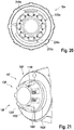
- the electrical interfaces 24a, 90a have a common coupling direction 40a.
- the mechanical interface 16a and the electrical interfaces 24a, 90a have a common coupling direction 40a.
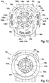
- the further electrical interface 24a has at least one contact surface 28a, 30a, 32a, 34a, which is arranged at least substantially in a contact plane which is arranged at least substantially perpendicular to the coupling direction 40a.
- the contact surface 28a, 30a, 32a, 34a is at least essentially flat.
- the at least one contact surface 28a, 30a, 32a, 34a has a surface normal which is arranged at least essentially parallel to the coupling direction 40a.
- the further electrical interface 24a of the tool base module 10a has a plurality of contact surfaces 28a, 30a, 32a, 34a.
- the electrical interface 24a of the tool base module 10a has sixteen contact surfaces 28a, 30a, 32a, 34a.
- only four contact surfaces 28a, 30a, 32a, 34a of the sixteen contact surfaces 28a, 30a, 32a, 34a are provided with a reference number.
- the contact surfaces 28a, 30a, 32a, 34a of the further electrical interface 24a are all designed to be at least essentially flat and are arranged in the contact plane.
- the coupling device has at least one at least partially disk-shaped carrier element 42a with an end face on which the at least one contact surface 28a, 30a, 32a, 34a is arranged. All contact surfaces 28a, 30a, 32a, 34a of the further electrical interface 24a are arranged on the end face.
- the end face and the contact faces 28a, 30a, 32a, 34a at least essentially form a continuous surface.
- the end face and the contact faces 28a, 30a, 32a, 34a are arranged at least essentially coplanar.
- the carrier element 42a is made of plastic. In a mounted state, the carrier element 42a is immovably connected to the housing 152a of the tool base module 10a.
- the carrier element 42a is in the present Embodiment formed in one piece with a housing part.
- the end face of the carrier element 42a is formed essentially in the shape of a circular ring. It has a disk plane which defines the direction of the contact plane of the further electrical interface 24a.
- the end face of the carrier element 42a, on which the contact surfaces 28a, 30a, 32a, 34a of the further electrical interface 24a are arranged, has the contact surface of the coupling device for the attachment device 18a.
- the disk-shaped carrier element 42a has an outer circumference from which the at least one contact surface 28a, 30a, 32a, 34a is arranged at a distance.
- the outer circumference of the carrier element 42a corresponds to a circumference of an outer circle of the annular carrier element 42a.
- the contact surfaces 28a, 30a, 32a, 34a of the electrical interface 24a are all arranged at a distance from the outer circumference of the carrier element 42a.
- the contact surfaces 28a, 30a, 32a, 34a are arranged in the radial direction within the outer circumference of the carrier element 42a.
- the further electrical interface 24a has at least two contact interfaces 46a, 48a of the same type.
- the further electrical interface 24a has eight contact interfaces 46a, 48a of the same type.
- FIG 3 For the sake of clarity, only two of the contact interfaces 46a, 48a are provided with reference symbols.
- Each of the contact interfaces 46a, 48a comprises two contact surfaces 28a, 30a, 32a, 34a, which have a different electrical polarity in at least one operating state.
- the contact interfaces 46a, 48a are designed redundantly to one another.
- the contact interfaces 46a, 48a are designed to be functionally equivalent to one another.
- the contact surfaces 28a, 30a, 32a, 34a of two different contact interfaces 46a, 48a are arranged offset from one another in the circumferential direction.
- the contact surfaces 28a, 30a, 32a, 34a of two contact interfaces 46a, 48a arranged adjacently in the circumferential direction each have an intermediate angle of at least substantially 45 degrees.
- the positions of the contact surfaces 28a, 30a, 32a, 34a of two contact interfaces 46a, 48a merge into one another through a rotation about the main output axis 68a of the tool base module 10a.
- the contact interfaces 46a, 48a are provided to electrically connect the attachment device 18a to the tool base module 10a in eight different angular positions, based on the main output axis 68a of the tool base module 10a.
- the further electrical interface 24a has at least one contact surface ring 60a.
- the contact surface ring 60a comprises eight of the contact surfaces 28a, 30a of the further electrical interface 24a. Eight different contact interfaces 46a, 48a of the further electrical interface 24a are assigned to the eight contact surfaces 28a, 30a of the contact surface ring 60a.
- the contact surfaces 28a, 30a of the contact surface ring 60a are at least essentially at the same distance from the output shaft 142a of the tool base module 10a.
- the contact surfaces 28a, 30a of the contact surface ring 60a are arranged in a ring.
- the contact surfaces 28a, 30a of the contact surface ring 60a are arranged distributed uniformly in the circumferential direction.
- Contact surfaces 28a, 30a that are adjacent in the circumferential direction are each offset from one another by an angle of 45 degrees.
- the contact surfaces 28a, 30a are designed in the form of circular ring sections, which are arranged concentrically to the contact surface ring 60a.
- a main direction of extent of the contact surfaces 28a, 30a is arranged at least substantially parallel to a circumferential direction.
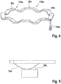
- the contact surface rim 60a is formed by a single contact element 64a (cf. Figure 4 ). It is also conceivable that the contact surface ring 60a is formed by a plurality of contact elements.
- the contact surfaces 28a, 30a of the contact surface ring 60a have the same electrical potential in at least one active operating state of the electrical interface 24a.
- the contact element 64a is formed at least essentially in the shape of a circular ring.
- the contact element 64a has eight elevations 156a, 158a in the axial direction. In Figure 4 For the sake of clarity, only two of the elevations 156a, 158a are provided with reference symbols.
- the surfaces of the elevations 156a, 158a form the contact surfaces 28a, 30a of the contact surface ring 60a.
- the elevations 156a, 158a have at least essentially the same height in relation to a base plane of the contact surface rim 60a.
- the elevations 156a, 158a are arranged uniformly distributed in the circumferential direction. Elevations 156a, 158a that are adjacent in the circumferential direction are offset from one another by an angle of 45 degrees.
- the contact element 64a has a contact tab 160a.
- the contact lug 160a is provided for connecting the contact element 64a.
- the further electrical interface 24a has at least one further contact surface ring 62a, which is arranged at least essentially concentrically with the contact surface ring 60a.
- the further contact surface ring 62a includes in the In the present exemplary embodiment, eight more of the contact surfaces 32a, 34a of the further electrical interface 24a.
- the eight further contact surfaces 32a, 34a of the further contact surface ring 62a are each assigned to eight different contact interfaces 46a, 48a of the further electrical interface 24a.
- One contact surface 32a, 34a of the further contact surface ring 62a is assigned to one contact surface 28a, 30a of the contact surface ring 60a.
- One contact surface 32a, 34a of the additional contact surface ring 62a and one contact surface 28a, 30a of the contact surface ring 60a are assigned to a common contact interface 46a, 48a.
- the contact surfaces 28a, 30a of the contact surface ring 60a and the contact surfaces 32a, 34a of the further contact surface ring 62a are arranged at least essentially alternating in the circumferential direction.
- a respective contact surface 32a, 34a of the further contact surface ring 62a is arranged at least essentially in a gap between two adjacent contact surfaces 28a, 30a of the contact surface ring 60a.
- the contact surfaces 32a, 34a of the further contact surface ring 62a are at least substantially the same distance from the output shaft 142a of the tool base module 10a.
- the contact surfaces 32a, 34a of the further contact surface ring 62a are arranged in a ring.
- the contact surfaces 32a, 34a of the further contact surface ring 62a are arranged uniformly distributed in the circumferential direction.
- Contact surfaces 32a, 34a that are adjacent in the circumferential direction are each offset from one another by an angle of 45 degrees.
- the contact surfaces 32a, 34a are designed in the form of circular ring sections which are arranged concentrically with the further contact surface ring 62a.
- a main direction of extent of the contact surfaces 32a, 34a is arranged at least substantially parallel to a circumferential direction.
- the further contact surface ring 62a and the contact surface ring 60a have different radii.
- the further contact surface ring 62a has a smaller radius than the contact surface ring 60a.
- the contact surfaces 28a, 30a of the contact surface ring 60a are arranged at a radial distance from the contact surfaces 32a, 34a of the further contact surface ring 62a.
- the contact surfaces 28a, 30a of the contact surface ring 60a are at a distance from the outer circumference of the carrier element 42a of at least substantially 0.5 mm.
- the contact surfaces 32a, 34a of the further contact surface ring 62a are at a distance from the outer circumference of the carrier element 42a of at least substantially 2.5 mm.
- the further contact surface ring 62a is formed by a single further contact element 66a. It is also conceivable that the further contact surface ring 62a is formed by a plurality of contact elements.
- the contact surfaces 32a, 34a of the further contact surface ring 62a have the same electrical potential in at least one active operating state of the electrical interface 24a.
- the further contact element 66a is designed analogously to the contact element 66a.
- the further contact element 66a is formed at least essentially in the shape of a circular ring.
- the further contact element 66a has eight elevations in the axial direction. The surfaces of the elevations form the contact surfaces 32a, 34a of the further contact surface ring 62a.
- the elevations have at least essentially the same height in relation to a base plane of the further contact surface ring 62a.
- the elevations are evenly distributed in the circumferential direction. Elevations that are adjacent in the circumferential direction are offset from one another by an angle of 45 degrees.
- the contact element 66a has a contact tab. The contact tab is provided for connecting the contact element 66a.
- the carrier element 42a has a relief ring on a side facing away from the contact plane.
- the relief ring has a shape which corresponds to the contact element 64a of the contact surface ring 60a.
- the carrier element 42a has eight openings along the relief ring. In an assembled state, the contact element 64a is inserted into the carrier element 42a.
- One elevation 156a, 158a is each assigned to one of the openings.
- a respective elevation 156a, 158a is visible in each case on one of the openings on the end face of the carrier element 42a.
- the carrier element 42a has a further relief ring on the side facing away from the contact plane.
- the further relief ring has a shape which corresponds to a shape of the further contact element 66a.
- the carrier element 42a has eight openings along the further relief ring.
- the carrier element 42a has a total of sixteen openings.
- the further contact element 64a is inserted into the carrier element 42a.
- One elevation is assigned to one of the openings.
- One elevation is visible in each case on one of the openings on the end face of the carrier element 42a.
- the coupling device of the tool base module 10a has a locking unit 72a for locking the attachment device 18a (cf. Figure 3 ).
- the locking unit 72a is arranged at the main exit 14a.
- the locking unit 72a is provided to lock the housing 152a of the attachment device 18a to the housing 130a of the tool base module 10a.
- the locking unit 72a is provided to connect the housing 152a of the attachment device 18a to the housing 130a of the tool base module 10a axially and in a rotationally secure manner.
- the attachment device 18a has a locking unit 372a which corresponds to the locking unit 72a.
- the locking unit 72a has at least one securing element 162a for axially securing a connection between the housings 130a, 152a.
- the securing element 162a is designed as a groove running around the circumference.
- the securing element 162a is arranged on the housing 130a of the tool base module 10a.
- the securing element can be designed as a rib and / or can be arranged on the output shaft 142a.
- the attachment device 18a has a securing element 362a designed to correspond to the securing element 162a (cf. Figure 2 ), which is provided for engagement in the securing element 162a.
- the securing element 362a is designed as a latching element.
- the latching element can be designed as a latching spring, for example.
- the securing element 362a of the attachment device 18a is used to axially secure the attachment device 18a to the housing 130a.
- the securing element 162a and the securing element 362a form a form-fit and / or force-fit connection in a coupled state.
- the securing element 162a and the securing element 362a can be provided for an at least partially non-positive connection.
- the attachment device 18a comprises an unlocking ring 164a for releasing the attachment device 18a from the tool base module 10a.
- the unlocking ring 164a is part of the locking unit 372a.
- the locking unit 372a effects the releasable mechanical connection of the attachment device 18a to the housing 130a of the tool base module 10a.
- the unlocking ring 164a is arranged in a coupled state on an end of the attachment device 18a facing the tool base module 10a.
- the unlocking ring 164a is rotatably mounted in the circumferential direction on the attachment device 18a and provided for manual operation.
- the unlocking ring 164a is provided to tension and release the securing element 362a in the form of a latching element for separating the attachment device 18a from the tool base module 10a.
- the locking unit 72a has a further securing element 166a, which is provided to prevent rotation.
- the further securing element 166a is formed in one piece with the housing 130a of the tool base module 10a.
- the further securing element 166a is designed as a toothed ring and has eight teeth 168a which are arranged evenly distributed in the circumferential direction. For the sake of clarity, only one of the teeth 168a is provided with a reference number.
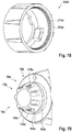
- the attachment device 18a has a receptacle 170a formed to correspond to the further securing element 166a with a securing element 366a (cf. Figure 8 ) on.
- the securing element 366a is accordingly also provided to prevent rotation.
- the securing element 366a is designed as a ring gear, the teeth 368a of which are arranged uniformly distributed in the circumferential direction.
- the further securing element 166a engages in the securing element 366a of the receptacle 170a of the attachment device 18a.
- the further securing element 166a transmits forces acting in the circumferential direction on the attachment device 18a to the housing 130a of the tool base module 10a via the securing element 366a.
- the securing element 362a embodied as a latching element engages in the securing element 162a embodied as a groove and transfers forces acting in the axial direction on the attachment device 18a to the housing 130a of the tool base module 10a.
- the tool holder 154a and the at least one locking unit 72a are arranged at least essentially on the same side of the contact plane of the electrical interface 24a in relation to a direction of the main output shaft 68a.
- the tool holder 154a, the axial securing element 162a designed as a groove and the further securing element 166a are arranged at least essentially on the same side of the contact plane of the electrical interface 24a in relation to a direction of the main output axis 68a.
- the gear unit 144a of the tool base module 10a is arranged on a different side of the contact plane than the locking unit 72a and / or the tool holder 154a in relation to the direction of the main output axis 68a.
- the electrical interface 324a of the attachment device 18a has at least one contact element 76a, 78a (cf. Figure 2 ) or 80a, 82a (cf. Figure 8 ) on.
- the contact elements 76a, 78a are provided to translate a closing movement for a connection of the attachment device 18a into a frictional movement that is at least substantially perpendicular to a direction of the closing movement is aligned (cf. Figure 2 ).
- the electrical interface 324a of the attachment device 18a is designed to correspond to the further electrical interface 24a of the tool base module 10a and thus forms an electrical counter-interface.
- the mating interface has a first one of the contact elements 76a and another one of the contact elements 78a.
- the first contact element 76a is provided for contact with the contact element 64a of the further electrical interface 24a.
- the further contact element 78a is provided for contact with the further contact element 66a of the further electrical interface 24a.
- the contact elements 76a, 78a of the mating interface are designed as spring contact elements in the embodiment shown.
- the contact elements 76a, 78a of the mating interface are provided to provide a contact spring force in the axial direction.
- the contact elements 76a, 78a are designed as arc springs.
- the contact elements 76a, 78a each have an arched curve in the axial direction.
- the first contact element 76a of the mating interface has a radial distance from the output shaft 142a which corresponds to the radial distance of the contact element 64a of the further electrical interface 24a from the output shaft 142a and the further contact element 78a of the mating interface has a radial distance from the Output shaft 142a, which corresponds to the radial distance of the further contact element 66a of the further electrical interface 24a from the output shaft 142a.
- the contact elements 76a, 78a of the electrical interface 324a are each at least essentially immovably fixedly connected to the housing 152a of the attachment device 18a on one side (cf. Figure 5 ).
- the attachment device 18a is placed in the coupling direction 40a on the tool base module 10a and the contact elements 76a, 78a of the counter-interface come into contact with the contact elements 64a, 66a of the further electrical interface 24a.
- the contact elements 76a, 78a each have an apex which comes into contact with the contact elements 64a, 66a of the further electrical interface 24a.
- the apexes of the arch are pushed along the contact elements 64a, 66a of the further electrical interface 24a and execute a friction movement with respect to the contact elements 64a, 66a of the further electrical interface 24a.
- the rubbing movement makes it possible, as a cleaning movement, to remove a deposit on the contact surfaces 28a, 30a, 32a, 34a of the contact elements 64a, 66a, 76a, 78a.
- the further attachment device 20a has a saw blade 172a (cf. Figure 6 ).
- the further attachment device 20a has an electrical interface 390a designed to correspond to the electrical interface 90a designed as a power interface as a counter interface.
- the further attachment device 20a has an electrical interface 324a configured to correspond to the further electrical interface 24a as a further counter-interface.
- the electrical interface 324a embodied as a further counter-interface has two contact elements 80a, 82a, which are embodied analogously to the contact elements 76a, 78a of the first attachment device 18a.
- the further attachment device 20a is provided for an electrical connection by means of the electrical interface 90a and the further electrical interface 16a.
- the further attachment device 20a comprises a housing 174a and an unlocking ring 176a, which is designed analogously to the unlocking ring 164a of the attachment device 18a configured as an angle attachment.
- the further attachment device 20a comprises at least one electrical energy utilization unit 126a, which is designed as an electric motor.
- the energy utilization unit 126a is provided to drive the saw blade 172a (cf. Figure 7 ).
- the energy utilization unit 126a is provided to drive the saw blade 172a independently of the drive unit 12a of the tool base module 10a.
- the at least one electrical energy utilization unit 126a has a maximum power consumption which corresponds to at least 90 percent of a maximum power consumption of the drive unit 12a of the tool base module 10a.
- the further attachment device 20a comprises a further electrical energy utilization unit, for example a lamp, which is supplied with energy via the further electrical interface 24a in at least one operating state.
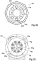
- the electrical interface 90a designed as a power interface has at least two plug-in elements 92a, 94a.
- the two plug-in elements 92a, 94a are designed in the same way.
- the electrical interface 90a also has at least one insulator element 104a, which is spatially arranged between the plug-in elements 92a, 94a at least in a connected state.
- the plug-in elements 92a, 94a are designed to receive mating plug-in elements 180a, 182a of the attachment device 20a that are designed to correspond to the plug-in elements 92a, 94a.
- the plug-in elements 92a, 94a are designed as tulip plugs.
- the mating plug elements 180a, 182a are designed as pins or blades in the present exemplary embodiment.
- the plug elements 92a, 94a are each arranged in an opening 184a, 186a in the carrier element 42a.
- the mating plug-in elements 180a, 182a of the attachment device 20a designed as pins or blades, penetrate the openings 184a, 186a in a connected state.
- the insulator element 104a is designed as a web made of an electrical non-conductor.
- the isolator element 104a is designed as a web made of plastic.
- plug-in elements 92a, 94a are designed in the form of tulip plugs on the attachment device 20a, and that the tool base module 10a corresponding to the plug-in elements 92a, 94a designed mating plug-in elements 180a, 182a in the form of pins or Has blades formed recordings.
- the coupling device comprises a mechanical protective element 188a for protecting the mating plug-in elements 180a, 182a of the attachment device 20a, which are designed as pins, from mechanical action.
- the protective element 188a is designed as a housing projection.
- the protective element 188a is arranged on an edge of the housing 174a of the attachment device 20a (cf. Figure 8 ).
- the protective element 188a projects axially beyond the unlocking ring 164a of the attachment device 20a.
- the protective element 188a is arranged axially and radially on the same side of the housing 174a as the mating plug-in elements 180a, 182a.
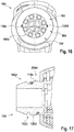
- the plug-in elements 92a, 94a of the electrical interface 90a designed as a power interface have at least one contact element 118a, 120a, 122a, 124a, which is provided for a cleaning movement of a contact surface, in particular for a grinding movement (cf. Figures 9, 27 ).
- the plug-in elements 92a, 94a of the electrical interface 90a are designed analogously to one another, which is why only one plug-in element 92a is described in more detail below.
- the plug element 92a is designed as a tulip plug. In the present exemplary embodiment, the plug element 92a has two pairs of contact elements 118a, 120a, 122a, 124a.
- the contact elements 118a, 120a, 122a, 124a are each designed as contact springs.
- Contact elements 118a, 120a, 122a, 124a of a pair are prestressed against one another and each have an apex at which they touch.
- the contact elements 118a, 120a, 122a, 124a of a pair are designed analogously to one another and arranged in mirror image to one another.
- the pairs of contact elements 118a, 120a, 122a, 124a are related to a main direction of extent of the contact elements 118a, 120a, 122a, 124a, arranged laterally offset from one another.
- the receptacle has only one pair of contact elements or a larger number of pairs of contact elements other than two.
- the contact elements 118a, 120a, 122a, 124a of a pair of contact elements 118a, 120a, 122a, 124a are each provided to interact with a pin or a blade 180a, 182a of the attachment device 20a and to establish an electrical contact during a coupling process.
- the contact elements 118a, 120a, 122a, 124a and the pin or blade 180a, 182a each have a contact surface.
- the contact elements 118a, 120a, 122a, 124a perform a grinding movement relative to the pin, which corresponds to a cleaning movement of the contact surfaces.
- the contact elements 118a, 120a, 122a, 124a of the electrical interface 90a designed as a power interface apply a pressing force of at least 5 N to the contact surfaces in a connected state.
- the pressing force of a first contact element 118a, 122a of a pair is opposite to the pressing force of a second contact element 120a, 124a of the pair aligned.
- the contact elements 118a, 120a, 122a, 124a are in contact with the mating plug element 180a, 182a on opposite sides of the associated mating plug element 180a, 182a of the attachment device 20a.
- the electrical interface 90a of the coupling device designed as a power interface, couples a first electrical connection of the attachment device 18a, 20a, 22a to the mechanical connection and the further electrical interface 24a of the coupling device couples a further electrical connection of the attachment devices 18a, 20a, 22a to the mechanical connection.
- the third attachment device 22a embodied as a hot-melt adhesive attachment has an energy utilization unit 128a which is embodied as an adhesive heater.
- the attachment device 22a has a coupling area 190a, an adhesive storage area 192a and a heating area 194a, which are arranged adjacent to one another in an axial direction.
- the adhesive storage area 192a is designed as a slide-in compartment.
- the third attachment device 22a has a housing 196a with a conical basic shape (cf. Figure 10 ). The housing 196a tapers from the coupling area 190a via the adhesive storage area 192a to the heating area 194a.
- the heating area 194a is tapered and has an adhesive tip 198a as a working outlet 354a of the attachment device 22a, which has a nozzle as an outlet for an adhesive.
- the housing 196a forms an adhesive storage container 200a in the adhesive storage area 192a, which is provided for receiving 170a an adhesive, for example an adhesive stick (cf. Figure 11 ). It is also conceivable that the adhesive storage container 200a is provided for an adhesive in the form of granules.
- the energy utilization unit 128a embodied as an adhesive heater is arranged in the heating area 194a of the attachment device 22a and has a heating coil. The energy utilization unit 128a is provided for converting electrical energy of the energy supply 136a into heat and, in an operating state, heats the adhesive.
- the adhesive is designed as a hot-melt adhesive.
- the energy utilization unit 128a is supplied with energy in at least one operating state via the electrical interface 90a embodied as a power interface.
- the third attachment device 22a has a feed unit with an operating element 202a which is provided for transporting adhesive.
- the operating element 202a is designed as a lever.
- the operating element 202a penetrates the housing 196a and has an outer lever arm and an inner lever arm.
- the operating element 202a has a bearing point spatially between the outer lever arm and the inner lever arm, which is designed as a pivot point and in which the operating element 202a is mounted pivotably with respect to the housing 196a.
- a main direction of extent of the handle 132a, the main output shaft 68a of the main output 14a and the operating element 202a are arranged.
- the operating element 202a is arranged rotated relative to the main output axis 68a. It is also conceivable that the operating element 202a is designed as a sliding element and / or comprises a spring element which is provided to provide a force for transporting the adhesive or a restoring force. It is also conceivable that the attachment device 22a has a feed unit for transporting adhesive without an operating element 202a. In an alternative embodiment, the attachment device 22a can have a feed unit which is designed as a linear drive, for example a screw drive, that can be mechanically coupled to the output shaft 142a of the tool base module 10a and is provided to use a rotary movement of the drive unit 12a of the tool base module 10a for transporting adhesive .
- a linear drive for example a screw drive
- a user operates the main switch 138a arranged on the tool base module 10a and connects the energy utilization unit 128a of the attachment device 22a to the energy supply 136a of the tool base module 10a.
- the energy utilization unit 128a embodied as an adhesive heater heats an adhesive located in the heating area 194a of the attachment device 22a.
- the user actuates the operating element 202a of the attachment device 22a to transport the adhesive and thus pushes the adhesive from the adhesive reservoir 200a into the heating area 194a, whereby the adhesive emerges from the nozzle of the adhesive tip 198a and reaches a body to be glued.
- Figure 12 shows a tool base module 10b for independent use of a further exemplary embodiment.
- the tool base module 10b has an energy utilization unit, not shown in detail, as well as a main output and a coupling device which has a mechanical interface 16b for a drive-related mechanical connection of at least one attachment device to the main output.
- the coupling device comprises an electrical interface 90b for transmitting a large amount of power and / or a large current, which is provided for an electrical connection, coupled to the mechanical connection, of the at least one attachment device at the main output.
- the electrical interface 90b is designed as a power interface.
- the coupling device has a further electrical interface 24b for transmitting a small amount of power and / or a small current, which is connected to a further electrical connection of the at least one attachment device coupled to the mechanical connection the main exit is provided. It is conceivable that the coupling device only comprises the electrical interface 90b designed as a power interface, ie that the further electrical interface 24b is omitted.
- the interface 24b embodied as a power interface has at least two contact interfaces 112b, 114b, 116b of the same type for transmitting a high current and / or a high power.
- Each of the contact interfaces 112b, 114b, 116b each comprises two plug-in elements 92b, 94b, 96b, 98b, 100b, 102b, which have a different electrical polarity in at least one operating state.
- Each of the contact interfaces 112b, 114b, 116b each has an insulator element 104b, 106b, 108b.
- Each of the isolator elements 104b, 106b, 108b is at least in a connected state spatially between two of the plug-in elements 92b, 94b, 96b, 98b, 100b, 102b.
- the contact interfaces 112b, 114b, 116b are redundant to one another.
- the contact interfaces 112b, 114b, 116b are designed to be functionally equivalent to one another.
- the electrical interface 24b embodied as a power interface has three contact interfaces 112b, 114b, 116b.
- the plug-in elements 92b, 94b, 96b, 98b, 100b, 102b of two different contact interfaces 112b, 114b, 116b are arranged offset from one another in the circumferential direction.
- the plug-in elements 92b, 94b, 96b, 98b, 100b, 102b of two contact interfaces 112b, 114b, 116b arranged adjacently in the circumferential direction have intermediate angles of 90 degrees, 90 degrees and 180 degrees.
- the positions of two contact interfaces 112b, 114b, 116b merge into one another due to a rotation about the main output axis of the tool base module 10b.
- the contact interfaces 112b, 114b, 116b are provided to electrically connect the attachment device to the tool base module 10b in three different angular positions, based on the main output axis of the tool base module 10b.
- the electrical interfaces 24b, 90b have a common coupling direction.
- the mechanical interface 16b and the electrical interfaces 24b, 90b have a common coupling direction.
- the further electrical interface 24b has sixteen contact surfaces 28b, 30b, 32b, 34b analogously to the previous exemplary embodiment, which are arranged at least substantially in a contact plane which is arranged at least substantially perpendicular to the coupling direction.
- the coupling device of the tool base module 10b has a locking unit 72b for locking the attachment device.
- the locking unit 72b is arranged at a main output 14b.
- the locking unit 72b is provided to lock a housing of the attachment device with a housing 130b of the tool base module 10b.
- the locking unit 72b has a securing element (not shown in more detail) for axially securing a connection between the housing 130b of the tool base module 10b and a housing of the attachment device.
- the locking unit 72b has a further securing element 166b, which is provided to prevent rotation.
- the further securing element 166b is designed as a toothed ring and has eight teeth 168b which are arranged evenly distributed in the circumferential direction. For the sake of clarity, only one of the teeth 168b is provided with a reference number.
- Figure 13 shows a tool base module 10c of a further exemplary embodiment.
- the tool base module 10c is intended, in particular, for independent use.
- the tool base module 10c has an energy utilization unit (not shown in more detail) as well as a main output and a coupling device which has a mechanical interface 16c for a drive-related mechanical connection of at least one attachment device to the main output.
- the coupling device comprises an electrical interface 90c for transmitting a large amount of power and / or a large current, which is provided for an electrical connection of the at least one attachment device coupled to the mechanical connection at the main output.
- the electrical interface 90c is designed as a power interface.
- the coupling device has a further electrical interface 24c for transmitting a small amount of power and / or a small current, which is provided for a further electrical connection of the at least one attachment device to the main output that is coupled to the mechanical connection. It is conceivable that the coupling device only comprises the electrical interface 90c designed as a power interface, ie that the further electrical interface 24c is omitted.
- the tool base module 10c has a locking unit 72c for locking the attachment device.
- the locking unit 72c is arranged at the main exit.
- the locking unit 72c has at least one securing element 162c for axially securing a connection between the housings (cf. Figure 14 ).
- the securing element 162c is designed as a groove running around the circumference.
- the locking unit 72c has a further securing element 166c, which is provided to prevent rotation.
- the further securing element 166c is designed in one piece with the housing of the tool base module 10c.
- the further securing element 166c is designed as a toothed ring and has eight teeth 168c which are arranged evenly distributed in the circumferential direction. For the sake of clarity, only one of the teeth 168c is provided with a reference number.
- the electrical interface 90c designed as a power interface and the further electrical interface 24c are integrated in the locking unit 72c.
- the electrical interface 90c designed as a power interface and the further electrical interface 90c have contact elements 64c, 66c, 118c, 120c designed analogously to one another.
- the contact elements 64c, 66c, 118c, 120c are each arranged on an outer circumference on a base section 204c of the locking unit 72c.
- Contact elements 64c, 66c, 118c, 120c arranged adjacent to one another in the circumferential direction have an intermediate angle of at least substantially 90 degrees, based on a main output axis of the main output.
- the contact elements 118c, 120c of the electrical interface 90c embodied as a power interface are arranged opposite one another.
- the contact elements 64c, 66c of the further electrical interface 90c are arranged opposite one another. Only one of the contact elements 64c is described in more detail below.
- the contact element 64c comprises a pin 206c which is axially movably mounted in the further securing element 166c. In an uncoupled state, the pin 206c protrudes beyond an end face of the securing element 166c.
- the pin 206c is provided to be displaced during a coupling process.
- the contact point has a joint 208c that connects the pin 206c to a contact surface of the contact element 64c and that is provided to translate an axial movement of the pin into a radial movement of the contact surface outward.
- Figure 15 shows a release ring 164c of the attachment device.
- Contact elements 210c, 212c, 214c, 216c corresponding to the contact elements 64c, 66c, 118c, 120c are arranged on the unlocking ring 164c.
- the contact elements 210c, 212c, 214c, 216c of the attachment device are arranged distributed in the circumferential direction corresponding to the contact elements 64c, 66c, 118c, 120c of the electrical interface 90c.
- the contact elements 210c, 212c, 214c, 216c of the unlocking ring 164c come into contact with the contact surfaces of the contact elements 64c, 66c, 118c, 120c during the coupling movement.
- contact elements 64c, 66c, 118c, 120c are all assigned to a single electrical interface 24c, 90c and enable the attachment device to be connected in two different angular positions.
- an axial contact area of the electrical interfaces 24c, 90c is spatially arranged in the axial direction between the axial securing element 162c and a tool holder of the tool base module 10c.
- Figure 16 shows a tool base module 10d of a further embodiment.
- the tool base module 10d is intended, in particular, for independent use.
- the tool base module 10d has an energy utilization unit, not shown in detail, as well as a main output and a coupling device which has a mechanical interface 16d for a drive-related mechanical connection of at least one attachment device to the main output.
- the coupling device comprises an electrical interface 90d for transmitting a large amount of power and / or a large current, which is provided for an electrical connection of the at least one attachment device coupled to the mechanical connection at the main output.
- the electrical interface 90d is designed as a power interface.
- the tool base module 10d has no further electrical interface. It is also conceivable that the electrical interface 90d is provided as an interface for the transmission of a small power and / or a small current.
- the tool base module 10d has a locking unit 72d for locking the attachment device.
- the locking unit 72d is arranged at the main exit.
- the locking unit 72d has at least one securing element 162d for axial securing a connection of the housing.
- the securing element 162d is designed as a groove running around the circumference (cf. Figure 17 ).
- the locking unit 72d has a further securing element 166d, which is provided to prevent rotation.
- the further securing element 166d is designed in one piece with the housing of the tool base module 10d.
- the further securing element 166d is designed as a toothed ring and has eight teeth 168d which are arranged evenly distributed in the circumferential direction. For the sake of clarity, only one of the teeth 168d is provided with a reference number.
- the electrical interface 90d designed as a power interface is integrated in the locking unit 72d.
- the electrical interface 90d has two contact elements 118d, 120d.
- the contact elements 118d, 120d are each arranged on an outer circumference on a base section 204d of the locking unit 72d. In contrast to the previous exemplary embodiments, the contact elements 118d, 120d are arranged axially offset from one another.
- the contact elements 118d, 120d are each designed as a spring contact element.
- the attachment device has an unlocking ring 164d, which has contact elements 210d, 212d corresponding to contact elements 118d, 120d (cf. Figure 18 ).
- the contact elements 210d, 212d each have an annular contact surface.
- the contact elements 210d, 212d are arranged axially offset from one another in accordance with the contact elements 118d, 120d of the electrical interface 90d.
- the contact elements 210d, 212d of the unlocking ring 164d come into contact with contact surfaces of the contact elements 118d, 120d of the electrical interface 90d during the coupling movement.
- the locking unit 74d has a thread on the base section 204d into which the contact elements are integrated.
- the unlocking ring has a correspondingly designed thread into which contact elements of the attachment device are integrated.
- Figure 19 shows a tool base module 10e of a further exemplary embodiment.
- the tool base module 10e is intended, in particular, for independent use.
- the tool base module 10e has an energy utilization unit (not shown in more detail) and a main output and a coupling device that has a mechanical Has interface 16e to a mechanical drive connection of at least one attachment device 18e at the main output.
- the coupling device comprises an electrical interface 90e for transmitting a large amount of power and / or a large current, which is provided for an electrical connection of the at least one attachment device 18e to the main output that is coupled to the mechanical connection.
- the electrical interface 90e is designed as a power interface.
- the tool base module 10e has no further electrical interface. It is also conceivable that the electrical interface is provided as an interface for a transmission of a small power and / or a small current.
- the tool base module 10e has a locking unit 72e for locking the attachment device 18e.
- the locking unit 72e is arranged at the main exit.
- the locking unit 72e has an axial securing element 162e.
- the locking unit 72e has a further securing element 166e, which is provided to prevent rotation.
- the further securing element 166e is embodied in one piece with the housing of the tool base module 10e.
- the further securing element 166e is designed as a toothed ring and has eight teeth 168e which are arranged evenly distributed in the circumferential direction. For the sake of clarity, only one of the teeth 168e is provided with a reference number.
- the electrical interface 90e designed as a power interface is integrated in the locking unit 72e.
- the electrical interface 90e has sixteen contact elements 118e, 120e, each of which has a contact surface.
- the contact surfaces are each arranged on surfaces of the teeth 168e of the securing element 166e that are aligned in the circumferential direction. The contact surfaces are oriented in the direction of spaces arranged between the teeth 168e.
- contact surfaces are arranged which are identical in at least one operating state have first polarity.
- contact surfaces are arranged which, in at least one operating state, have the same polarity different from the first polarity.
- Other distributions of the polarities are also conceivable, for example contact surfaces provided for a different polarity can be arranged alternately in the circumferential direction.
- the attachment device 18e has a receptacle 170e designed to correspond to the further securing element 166e and which has eight counter teeth 226e (cf. Figure 20 ).
- the further securing element 166e engages in the receptacle 170e of the attachment device 18e.
- the attachment device 18e has sixteen contact elements 210e, 212e which are designed to correspond to the contact elements 118e, 120e and which are arranged on surfaces of the opposing teeth 226e that are oriented in the circumferential direction.
- one contact element 118e, 120e of the electrical interface 90e is in contact with one contact element 210e, 212e of the attachment device 18e.
- the attachment device 18e in an alternative embodiment has a smaller number of contact elements, for example four contact elements. In such an embodiment, the electrical interface enables the attachment device 18e to be connected in a plurality of angular positions.
- Figure 21 shows a tool base module 10f of a further exemplary embodiment.
- the tool base module 10f is intended, in particular, for independent use.
- the tool base module 10f has an energy utilization unit (not shown in more detail) as well as a main output and a coupling device which has a mechanical interface 16f for a drive-related mechanical connection of at least one attachment device 18f to the main output.
- the coupling device comprises an electrical interface 90f for transmitting a large amount of power and / or a large current, which is provided for an electrical connection of the at least one attachment device 18f to the main output that is coupled to the mechanical connection.
- the electrical interface 90f is designed as a power interface.
- the tool base module 10f has no further electrical interface. It is also conceivable that the electrical interface 90f as an interface to a Transmission of a small power and / or of a small current is provided.
- the tool base module 10f has a locking unit 72f for locking the attachment device 18f.
- the locking unit 72f is arranged at the main exit.
- the locking unit 72f has an axial securing element 162f.
- the locking unit 72f has a further securing element 166f, which is provided to prevent rotation.
- the securing element 166f is formed in one piece with the housing of the tool base module 10f.
- the further securing element 166f is designed as a toothed ring and has eight teeth 168f which are arranged evenly distributed in the circumferential direction.
- the electrical interface 90f designed as a power interface is integrated into the locking unit 72f.
- the electrical interface 90f has eight contact elements 118f, 120f, each of which has a contact surface.
- the contact surfaces are each arranged on radially outwardly oriented surfaces in spaces between the teeth 168f of the securing element 166f.
- contact surfaces are arranged which have the same first polarity in at least one operating state.
- contact surfaces are arranged which, in at least one operating state, have the same polarity that differs from the first polarity.
- Other distributions of the polarities are also conceivable, for example contact surfaces provided for different polarities can be arranged alternately in the circumferential direction.
- the attachment device 18f has a receptacle 170f designed to correspond to the further securing element 166f and which has eight counter teeth 226f (cf. Figure 22 ). In a coupled state, the further securing element 166f engages in the receptacle 170f of the attachment device 18f.
- the attachment device 18f has two contact elements 210f, 212f which are designed to correspond to the contact elements 118f, 120f and which are arranged on surfaces of the opposing teeth 226f which are directed radially inward.
- the contact elements 210f, 212f are designed as spring contact elements.
- the contact elements 210f, 212f of the attachment device 18f are each in contact with a contact element 118f, 120f of the electrical interface 90f.
- the interface 90f is provided to connect the attachment device 18f in one of four different angular positions. It is conceivable that the attachment device 18f in an alternative embodiment has a number of contact elements other than four.
- Figure 23 shows a tool base module 10g of a further embodiment.
- the tool base module 10g is intended, in particular, for independent use.
- the tool base module 10g has an energy utilization unit, not shown in detail, as well as a main output and a coupling device which has a mechanical interface 16g for a drive-related mechanical connection of at least one attachment device 18g to the main output.
- the coupling device comprises an electrical interface 90g for transmitting a large amount of power and / or a large current, which is provided for an electrical connection of the at least one attachment device 18g to the main output that is coupled to the mechanical connection.
- the electrical interface 90g is designed as a power interface.
- the tool base module 10g has no further electrical interface. It is also conceivable that the electrical interface is provided as an interface for a transmission of a small power and / or a small current.
- the tool base module 10g has a locking unit 72g for locking the attachment device 18g.
- the locking unit 72g is arranged at the main exit.
- the locking unit 72g has a securing element 166g which is provided to prevent rotation.
- the securing element 166g is formed in one piece with the housing of the tool base module 10g.
- the securing element 166g is designed as a toothed ring and has eight teeth 168g which are arranged evenly distributed in the circumferential direction.
- the electrical interface 90g designed as a power interface is integrated into the locking unit 72g.
- the electrical interface 90g has eight contact elements 118g, 120g, each of which has a contact surface.
- the contact surfaces are in each case on surfaces that are axially aligned in a main working direction of the tool base module 10g in intermediate spaces between the teeth 168g of the securing element 166g arranged.
- contact surfaces are arranged which have the same first polarity in at least one operating state.
- contact surfaces In an angular section which is complementary to the angular section, contact surfaces are arranged which, in at least one operating state, have the same polarity that differs from the first polarity.
- Other distributions of the polarities are also conceivable, for example contact surfaces provided for different polarities can be arranged alternately in the circumferential direction.
- the attachment device 18g has a receptacle 170g which is designed to correspond to the further securing element 166g and which has eight counter teeth 226g (cf. Figure 24 ). In a coupled state, the further securing element 166g engages in the receptacle 170g of the attachment device 18g.
- the attachment device 18g has two contact elements 210g, 212g which are designed to correspond to the contact elements 118g, 120g and which are arranged on axially directed end faces of the opposing teeth 226g.
- the contact elements 210g, 212g each have a spring-loaded pin.
- the contact elements 210g, 212g of the attachment device 18g are each in contact with a contact element 118g, 120g of the electrical interface 90g.
- the interface 90g is provided for connecting the attachment device 18g in one of four different angular positions. It is conceivable that the attachment device 18g in an alternative embodiment has a number of contact elements other than four. It is also conceivable that the tool base module 10g has a further electrical interface in an alternative embodiment. In such an embodiment, the contact elements are each assigned to one of the interfaces.
- Figure 25 shows a tool base module 10h of a further embodiment.
- the tool base module 10h is intended, in particular, for independent use.
- the tool base module 10h has an energy utilization unit (not shown in more detail) as well as a main output and a coupling device which has a mechanical interface 16h for a drive-related mechanical connection of at least one attachment device 18h to the main output.
- the coupling device comprises an electrical interface 90h for a transmission of a large power and / or a large current, which is connected to the mechanical Connection coupled electrical connection of the at least one attachment device 18h is provided at the main exit.
- the electrical interface 90h is designed as a power interface.
- the tool base module 10h has no further electrical interface. It is also conceivable that the electrical interface is provided as an interface for a transmission of a small power and / or a small current.
- the electrical interface 90h has a coupling direction.
- the main output has a main output shaft.
- the electrical interface 90h has at least one contact surface 218h, 220h which is arranged at least substantially in a contact plane which is arranged at least substantially perpendicular to the coupling direction.
- the contact surface 218h, 220h is at least essentially flat.
- the electrical interface 90h of the tool base module 10h has a plurality of contact surfaces 218h, 220h. In the present exemplary embodiment, the electrical interface 90h of the tool base module 10h has two contact surfaces 218h, 220h.
- the contact surfaces 218h, 220h of the electrical interface 90h are all at least substantially planar and are arranged in the contact plane.
- the contact surfaces 218h, 220h are annular.
- the contact surfaces 218h, 220h have a different polarity in at least one operating state.
- the contact surfaces 218h, 220h are arranged concentrically to one another.
- the contact surfaces 218h, 220h are arranged concentrically around a main output axis of the main output.
- the contact surfaces 218h, 220h have different diameters.
- the coupling device has at least one at least partially disk-shaped carrier element 42h with an end face on which the at least one contact surface 218h, 220h is arranged. All of the contact surfaces 218h, 220h of the electrical interface 90h are arranged on the end face.
- the carrier element 42h is immovably connected to the housing of the tool base module 10h.
- the carrier element 42h is designed in the shape of a circular ring. It has a disk plane which defines the direction of a contact plane of the electrical interface 90h.
- the end face of the carrier element 42h, on which the contact surfaces 218h, 220h of the electrical interface 90h are arranged, has the contact surface of the coupling device for the attachment device 18h.
- the attachment device 18h has an unlocking ring 164h which has contact elements 210h, 212h corresponding to the contact surfaces 218h, 220h.
- the contact elements 210h, 212h each have ring-shaped contact surfaces 222h, 224h.
- the contact elements 210h, 212h are elastic and have a wave structure in the axial direction.
- the contact elements 210h, 212h are arranged concentrically to one another, corresponding to the contact surfaces 218h, 220h of the electrical interface 90h.
- the contact elements 210h, 212h of the unlocking ring 164h come into contact with contact surfaces 218h, 220h of the electrical interface 90h during the coupling movement.
- the electrical interface 90h has at least essentially rectangular contact surfaces which are arranged at a different distance from the main output axis of the main output. It is also conceivable that, in an alternative embodiment, the carrier element 42h has annular recesses in which the contact surfaces of the electrical interface are arranged. In such an embodiment, the unlocking ring has pin-shaped or tongue-shaped contact elements which, in at least one connected state, engage in the annular recesses of the carrier element.
Landscapes
- Engineering & Computer Science (AREA)
- Mechanical Engineering (AREA)
- Secondary Cells (AREA)
- Portable Power Tools In General (AREA)
Description
- Es ist bereits ein Werkzeugbasismodul, insbesondere zu einer eigenständigen Nutzung, mit einer Antriebseinheit, mit einem Hauptausgang und mit einer Koppelvorrichtung, die eine mechanische Schnittstelle zu einer antriebstechnischen mechanischen Anbindung zumindest einer Aufsatzvorrichtung an dem Hauptausgang aufweist, vorgeschlagen worden. Ein Beispiel ist aus der
US2013118767A1 bekannt. - Die Erfindung geht aus von einem Werkzeugbasismodul, insbesondere zu einer eigenständigen Nutzung, mit einer Antriebseinheit, mit einem Hauptausgang und mit einer Koppelvorrichtung, die eine mechanische Schnittstelle zu einer antriebstechnischen mechanischen Anbindung zumindest einer Aufsatzvorrichtung an dem Hauptausgang aufweist.
- Es wird vorgeschlagen, dass die Koppelvorrichtung eine elektrische Schnittstelle zu einer Übertragung einer großen Leistung und/oder eines großen Stroms aufweist, die zu einer mit der mechanischen Anbindung gekoppelten elektrischen Anbindung der zumindest einen Aufsatzvorrichtung an dem Hauptausgang vorgesehen ist.
- Dadurch kann ein besonders vielseitig nutzbares Werkzeugbasismodul bereitgestellt werden. Es können Aufsatzvorrichtungen mit elektrischen Zusatzfunktionen genutzt werden. Ressourcen, wie beispielsweise eine Energieversorgung des Werkzeugbasismoduls, können besonders wirtschaftlich eingesetzt werden. Eine zusätzliche Energieversorgung für die Aufsatzvorrichtung kann eingespart werden. Es kann ein hoher Benutzerkomfort erreicht werden. Unter einem "Werkzeugbasismodul" soll in diesem Zusammenhang insbesondere eine Handwerkzeugmaschine verstanden werden. Unter einer "Handwerkzeugmaschine" soll in diesem Zusammenhang insbesondere eine werkstückbearbeitende, handgeführte Maschine, vorteilhaft jedoch eine Akku-Handwerkzeugmaschine, ein Schrauber, insbesondere ein Akku-Schrauber, ein Akku-Bohrschrauber, eine Bohrmaschine, ein Bohr- und/oder Schlaghammer, eine Säge, ein Hobel, eine Fräse, ein Schleifer, ein Winkelschleifer, ein Gartengerät und/oder ein Multifunktionswerkzeug verstanden werden. Eine werkstückbearbeitende, handgeführte Maschine ist dabei eine handgeführte Maschine zur Bearbeitung eines Werkstücks. Unter einer "eigenständigen Nutzung" soll in diesem Zusammenhang insbesondere eine Nutzung unabhängig von der Aufsatzvorrichtung, insbesondere allein, verstanden werden, beispielsweise zum Schrauben, Bohren, Schleifen und/oder Rühren. Insbesondere ist das Werkzeugbasismodul als solches ohne Aufsatzvorrichtung nutzbar. Vorzugsweise ist die Aufsatzvorrichtung in Verbindung mit dem Werkzeugbasismodul zu einer Nutzung vorgesehen, die von einer Nutzung des Werkzeugbasismoduls allein verschieden ist. Unter einem "Hauptausgang" soll in diesem Zusammenhang insbesondere ein Ausgang eines Hauptabtriebsstrangs des Werkzeugbasismoduls verstanden werden, insbesondere zu einer Übertragung eines Drehmoments und/oder einer Drehbewegung. Vorzugsweise wird der Hauptausgang von einer Abtriebswelle, insbesondere von einem freien Ende einer Abtriebswelle, gebildet. Zur Übertragung eines Drehmoments und/oder einer Drehbewegung auf die Aufsatzvorrichtung weist der Hauptausgang insbesondere einen polygonalen Querschnitt auf. Der polygonale Querschnitt dient der drehfesten Verbindung des Hauptausgangs mit der Aufsatzvorrichtung. Der Hauptausgang kann insbesondere eine Abtriebswelle mit einer Werkzeugaufnahme zu einer Aufnahme eines Einsatzwerkzeugs aufweisen. Insbesondere stellt die Antriebseinheit in zumindest einem Betriebszustand ein Drehmoment zu einem Antrieb der Abtriebswelle bereit. Insbesondere ist die Abtriebswelle zu einem Antrieb der Werkzeugaufnahme vorgesehen. Vorzugsweise weist der Hauptausgang eine Hauptabtriebsachse auf, die beispielsweise durch eine Drehachse der Abtriebswelle festgelegt ist. Vorzugsweise ist die Werkzeugaufnahme als eine Steck- und/oder Rastaufnahme ausgebildet. Bevorzugt weist die Werkzeugaufnahme eine Ausnehmung mit einem polygonalen Querschnitt zu einer Aufnahme des Einsatzwerkzeugs auf, wie beispielsweise eines Schraubbits, einer Bürste oder eines Rührers. Vorzugsweise ist die Ausnehmung als ein Innensechskant ausgebildet. Es ist denkbar, dass die Werkzeugaufnahme eine Verriegelungshülse aufweist. Es ist auch denkbar, dass die Werkzeugaufnahme zur Aufnahme und/oder Sicherung eines Einsatzwerkzeugs ohne eine Verriegelungshülse vorgesehen ist. Bei einer "eigenständigen Nutzung" des Werkzeugbasismoduls ist der Hauptausgang als Werkzeugaufnahme zur lösbaren Aufnahme eines Einsatzwerkzeugs ausgebildet und dient der Drehmomentübertragung auf das Einsatzwerkzeug. Dabei ist das Werkzeugbasismodul eigenständig ohne Aufsatzvorrichtung unter Verwendung eines Einsatzwerkzeugs nutzbar. Alternativ zu einer eigenständigen Nutzung kann das Werkzeugbasismodul auch zur Nutzung mit einer Aufsatzvorrichtung vorgesehen sein. Dabei findet eine Drehmomentübertragung von dem Hauptausgang auf die Aufsatzvorrichtung statt. Für die Nutzung des Werkzeugbasismoduls mit der Aufsatzvorrichtung weist das Werkzeugbasismodul eine Koppelvorrichtung mit einer mechanischen Schnittstelle auf.
- Das Werkzeugbasismodul umfasst neben der Antriebseinheit und dem Hauptausgang sowie der Koppelvorrichtung insbesondere auch eine Getriebeeinheit. Die Getriebeeinheit ist insbesondere dazu ausgebildet, eine Drehzahl der Antriebseinheit anzupassen, insbesondere zu verringern. Die Getriebeeinheit ist insbesondere als Untersetzungsgetriebeeinheit ausgeführt, mit der die Drehzahl der Antriebseinheit auf eine niedrigere Drehzahl des Hauptausgangs des Werkzeugbasismoduls angepasst wird. Insbesondere stellt die Antriebseinheit in zumindest einem Betriebszustand ein Drehmoment zu einem Antrieb der Abtriebswelle bereit. Vorzugsweise ist die Hauptabtriebsachse zumindest im Wesentlichen parallel zu einer Hauptarbeitsrichtung des Werkzeugbasismoduls ausgerichtet. Unter "zumindest im Wesentlichen parallel" soll hier insbesondere eine Ausrichtung einer Richtung relativ zu einer Bezugsrichtung, insbesondere in einer Ebene, verstanden werden, wobei die Richtung gegenüber der Bezugsrichtung eine Abweichung insbesondere kleiner als 8 Grad, vorteilhaft kleiner als 5 Grad und besonders vorteilhaft kleiner als 2 Grad aufweist. Der Ausdruck "zumindest im Wesentlichen senkrecht" soll hier insbesondere eine Ausrichtung einer Richtung relativ zu einer Bezugsrichtung definieren, wobei die Richtung und die Bezugsrichtung, insbesondere in einer Ebene betrachtet, einen Winkel einschließen, der insbesondere weniger als 8 Grad, vorteilhaft weniger als 5 Grad und besonders vorteilhaft weniger als 2 Grad von 90 Grad abweicht. Richtungsangaben wie "axial", "radial" und "in Umfangsrichtung" sollen insbesondere bezogen auf eine Richtung der Hauptabtriebsachse verstanden werden. Unter "axial" soll dabei insbesondere in Richtung der Hauptabtriebsachse verstanden werden. Unter "radial" soll senkrecht zu der Hauptabtriebsachse entlang einer Geraden, welche die Hauptabtriebsachse schneidet, nach außen verstanden werden. Unter "in Umfangsrichtung" soll entlang eines Kreises in einer Ebene senkrecht zu der Hauptabtriebsachse verstanden werden. Unter einer "Koppelvorrichtung" soll in diesem Zusammenhang insbesondere eine Vorrichtung verstanden werden, die dazu vorgesehen ist, ein Gehäuse des Werkzeugbasismoduls lösbar, insbesondere werkzeuglos lösbar, mit einem Gehäuse der Aufsatzvorrichtung zu verbinden. Die Koppelvorrichtung bewirkt eine lösbare, insbesondere werkzeuglos lösbare, elektrische und mechanische Anbindung der Aufsatzvorrichtung an dem Werkzeugbasismodul. Dazu weist die Koppelvorrichtung eine mechanische Schnittstelle auf. Die mechanische Schnittstelle ist dazu ausgebildet, eine antriebstechnische mechanische Anbindung der Aufsatzvorrichtung an dem Hauptausgang zu bewirken. Insbesondere bewirkt die mechanische Schnittstelle eine Drehmomentübertragung von dem Hauptausgang auf die Aufsatzvorrichtung. Die Koppelvorrichtung weist insbesondere ferner eine Verriegelungseinheit auf, mit der das Gehäuse des Werkzeugbasismoduls lösbar mechanisch, insbesondere werkzeuglos lösbar mechanisch mit dem Gehäuse der Aufsatzvorrichtung verbindbar ist. Die Verriegelungseinheit bewirkt insbesondere eine Axialsicherung und/oder eine Drehsicherung des Gehäuses der Aufsatzvorrichtung an dem Gehäuse des Werkzeugbasismoduls. Hierfür weist die Verriegelungseinheit zumindest ein Sicherungselement zur Axialsicherung und/oder zur Drehsicherung auf. Die Verriegelungseinheit kann zum Beispiel ein oder mehrere Sicherungselemente aufweisen, die sowohl eine Axialsicherung als auch eine Drehsicherung bewirken. Die Verriegelungseinheit kann alternativ ein oder mehrere Sicherungselemente aufweisen, die eine Axialsicherung oder eine Drehsicherung bewirken. Bei einer derartigen Verriegelungseinheit ist zumindest ein Sicherungselement für die Axialsicherung und zumindest ein Sicherungselement für die Drehsicherung vorgesehen. Das Sicherungselement für die Axialsicherung und das Sicherungselement für die Drehsicherung sind verschieden voneinander ausgebildet. Das zumindest eine Sicherungselement zur Axialsicherung und/oder Drehsicherung kann insbesondere als ein kraft- und/oder formschlüssiges Sicherungselement ausgebildet sein. Die Verriegelungseinheit weist ferner insbesondere ein Entriegelungselement auf. Das Entriegelungselement ist insbesondere dazu vorgesehen, die Verriegelung der Aufsatzvorrichtung an dem Gehäuse des Werkzeugbasismoduls zu lösen. Das Entriegelungselement ist insbesondere durch den Benutzer von Hand betätigbar. Das Entriegelungselement ist beispielhaft als drehbar gelagerter Entriegelungsring ausgeführt. Das Entriegelungselement ist vorzugsweise an der Aufsatzvorrichtung vorgesehen. Alternativ kann das Entriegelungselement auch an dem Gehäuse des Werkzeugbasismoduls vorhanden sein.
- Die Koppelvorrichtung weist ferner zumindest eine elektrische Schnittstelle auf. Die elektrische Schnittstelle ist insbesondere dazu ausgelegt, eine große Leistung und/oder einen großen Strom zu übertragen. Nachfolgend wird die elektrische Schnittstelle auch als Leistungsschnittstelle bezeichnet. Unter einer "großen Leistung" soll in diesem Zusammenhang insbesondere eine Leistung von wenigstens 20 W, vorzugsweise eine Leistung von wenigstens 40 W, bevorzugt eine Leistung von wenigstens 60 W und besonders bevorzugt eine Leistung von wenigstens 80 W verstanden werden. Unter einer mit der mechanischen Anbindung "gekoppelten Anbindung" soll in diesem Zusammenhang insbesondere eine sich zumindest im Wesentlichen gleichzeitig mit der mechanischen Anbindung schließende Anbindung verstanden werden. Vorzugsweise sind die mechanische Anbindung und die elektrische Anbindung dazu vorgesehen, in einer selben Schließbewegung geschlossen zu werden. Vorzugsweise ist die Koppelvorrichtung dazu vorgesehen, die mechanische Anbindung und die elektrische Anbindung der zumindest einen Aufsatzvorrichtung an dem Werkzeugbasismodul zu bewirken. Zum Beispiel kann die Koppelvorrichtung dazu vorgesehen sein, die mechanische und elektrische Anbindung mittels einer zumindest im Wesentlichen geradlinigen Bewegung der zumindest einen Aufsatzvorrichtung relativ zu dem Werkzeugbasismodul herzustellen. Insbesondere weist das Werkzeugbasismodul eine Energieversorgung auf, die in zumindest einem Betriebszustand Strom zu einer Versorgung der elektrischen Schnittstelle bereitstellt. Unter "vorgesehen" soll insbesondere speziell programmiert, ausgelegt und/oder ausgestattet verstanden werden. Darunter, dass ein Objekt zu einer bestimmten Funktion vorgesehen ist, soll insbesondere verstanden werden, dass das Objekt diese bestimmte Funktion in zumindest einem Anwendungs- und/oder Betriebszustand erfüllt und/oder ausführt.
- In vorteilhafter Weise ist die elektrische Schnittstelle zu einer Übertragung eines Stroms von wenigstens 2 A vorgesehen. Dadurch kann ein Werkzeugbasismodul zu einer Kopplung mit einer besonders leistungsstarken Aufsatzvorrichtung bereitgestellt werden. Es kann ein Werkzeugbasismodul zu einer Kopplung mit einer Aufsatzvorrichtung mit einem hohen Leistungsbedarf bereitgestellt werden. Vorzugsweise ist die elektrische Schnittstelle zu einer Übertragung eines Stroms von wenigstens 4 A, bevorzugt von wenigstens 10 A, besonders bevorzugt von wenigstens 20 A und ganz besonders bevorzugt von wenigstens 25 A vorgesehen. Insbesondere ist die elektrische Schnittstelle zu einer Übertragung eines Stroms zwischen dem Werkzeugbasismodul und der zumindest einen Aufsatzvorrichtung vorgesehen. Vorzugsweise ist die elektrische Schnittstelle zu einer Übertragung eines Stroms zu einer Energieversorgung einer elektrischen Energienutzungseinheit der zumindest einen Aufsatzvorrichtung vorgesehen. Vorzugsweise ist die elektrische Schnittstelle zu einer Übertragung einer Leistung vorgesehen, die wenigstens 50 Prozent, bevorzugt wenigstens 70 Prozent, besonders bevorzugt wenigstens 90 Prozent und ganz besonders bevorzugt wenigstens 100 Prozent einer maximalen Leistungsaufnahme der Antriebseinheit entspricht.
- Ferner wird vorgeschlagen, dass die elektrische Schnittstelle in einem gekoppelten Zustand einen elektrischen Widerstand von höchstens 15 mΩ aufweist. Dadurch kann eine besonders verlustarme Anbindung erreicht werden. Es kann ein Werkzeugbasismodul zu einer besonders effizienten Kopplung mit einer Aufsatzvorrichtung bereitgestellt werden. Unter einem "elektrischen Widerstand" der elektrischen Schnittstelle soll in diesem Zusammenhang insbesondere ein Kontaktwiderstand verstanden werden. Vorzugsweise weist die elektrische Schnittstelle in einem angebundenen Zustand einen Widerstand von höchstens 10 mΩ, bevorzugt von höchstens 5 mΩ und besonders bevorzugt von höchstens 3 mΩ auf.
- Die elektrische Schnittstelle für die Übertragung einer großen Leistung und/oder eines großen Stroms weist wenigstens ein, insbesondere zumindest zwei gleichartige, Kontaktelemente zur elektrischen Kontaktierung der Aufsatzvorrichtung mit dem Werkzeugbasismodul auf. Das wenigstens eine Kontaktelement ist insbesondere als elektrisches Steckelement ausgeführt. Das elektrische Steckelement kann insbesondere als Tulpenstecker ausgeführt sein.
- In einer vorteilhaften Ausgestaltung weist die elektrische Schnittstelle zumindest zwei Steckelemente und zumindest ein Isolatorelement auf, das zumindest in einem angebundenen Zustand räumlich zwischen den Steckelementen angeordnet ist. Dadurch kann ein Kurzschluss besonders wirksam vermieden werden. Es kann eine besonders sicheres und/oder zuverlässiges Werkzeugbasismodul bereitgestellt werden. Unter einem "Steckelement" soll in diesem Zusammenhang insbesondere ein Element zu einer Ausbildung einer elektrischen Steckverbindung verstanden werden, insbesondere eine Aufnahme, eine Aufnahmeöffnung, ein Klemm- und/oder Federelement oder ein Stift. Unter einem "Isolatorelement" soll in diesem Zusammenhang ein Bauteil aus einem elektrischen Nichtleiter, insbesondere aus einem festen Material, verstanden werden. Vorzugsweise weist die elektrische Schnittstelle zwei mittels des Isolatorelements getrennte Aufnahmeöffnungen auf, die dazu vorgesehen sind, jeweils ein korrespondierendes Steckelement der Aufnahmevorrichtung aufzunehmen.
- Ferner wird vorgeschlagen, dass die elektrische Schnittstelle zumindest zwei artgleiche Kontaktschnittstellen aufweist. Dadurch kann ein besonders flexibel koppelbares Werkzeugbasismodul bereitgestellt werden. Es kann ein besonders hoher Benutzerkomfort erreicht werden. Insbesondere sind die Kontaktschnittstellen redundant zueinander ausgebildet. Vorzugsweise sind die Kontaktschnittstellen bezogen auf die Hauptabtriebsachse des Hauptausgangs in einer Umfangsrichtung zueinander versetzt angeordnet. Vorzugsweise ist die elektrische Schnittstelle dazu vorgesehen, die Aufsatzvorrichtung bezogen auf die Hauptabtriebsachse des Hauptausgangs in einer von zumindest zwei unterschiedlichen Winkelpositionen elektrisch anzubinden. Bevorzugt ist die elektrische Schnittstelle dazu vorgesehen, die Aufsatzvorrichtung bezogen auf die Hauptabtriebsachse des Hauptausgangs in einer von zumindest drei unterschiedlichen Winkelpositionen, die vorzugsweise in Umfangsrichtung gleichverteilt angeordnet sind, elektrisch anzubinden. Besonders bevorzugt ist die elektrische Schnittstelle dazu vorgesehen, die Aufsatzvorrichtung bezogen auf die Hauptabtriebsachse des Hauptausgangs in einer von zumindest acht unterschiedlichen Winkelpositionen, die vorzugsweise in Umfangsrichtung gleichverteilt angeordnet sind, elektrisch anzubinden. Vorzugsweise weisen die Kontaktschnittstellen jeweils zumindest zwei verschiedenpolige Kontaktelemente auf.
- In einer vorteilhaften Ausgestaltung weist die Koppelvorrichtung zumindest eine weitere elektrische Schnittstelle zu einer Übertragung eines kleinen Stroms und/oder einer kleinen Leistung auf, die dazu vorgesehen ist, in einem gekoppelten Zustand zumindest einen von der elektrischen Schnittstelle unabhängigen Stromkreis zu schließen. Dadurch kann ein Einsatzbereich des Werkzeugbasismoduls weiter vergrößert werden. Unter einer "weiteren elektrischen Schnittstelle" soll in diesem Zusammenhang insbesondere eine Schnittstelle verstanden werden, die dazu vorgesehen ist, in einem gekoppelten Zustand zumindest einen Stromkreis zu schließen, der von der elektrischen Schnittstelle unabhängig ist. Unter einer "kleinen Leistung" soll in diesem Zusammenhang insbesondere eine Leistung von höchstens 4 W, vorzugsweise eine Leistung von höchstens 2 W, bevorzugt eine Leistung von höchstens 1 W und besonders bevorzugt eine Leistung von höchstens 0,1 W verstanden werden. Unter einem "kleinen Strom" soll in diesem Zusammenhang insbesondere ein Strom von höchstens 1000 mA, vorzugsweise von höchstens 500 mA, bevorzugt von höchstens 100 mA und besonders bevorzugt von höchstens 25 mA verstanden werden. Vorzugsweise ist die zumindest eine weitere elektrische Schnittstelle zu einer Übertragung eines Signals, insbesondere eines Signals zu einer Identifizierung eines Aufsatztyps der zumindest einen Aufsatzvorrichtung, vorgesehen. Vorzugsweise ist die zumindest eine weitere elektrische Schnittstelle zu einer mit der mechanischen Anbindung gekoppelten elektrischen Anbindung der zumindest einen Aufsatzvorrichtung an dem Hauptausgang vorgesehen.
- Die weitere elektrische Schnittstelle für die Übertragung einer kleinen Leistung und/oder eines kleinen Stroms weist insbesondere zumindest ein Kontaktelement zur elektrischen Kontaktierung der Aufsatzvorrichtung mit dem Werkzeugbasismodul auf. Das Kontaktelement weist eine Kontaktfläche auf. Die elektrische Schnittstelle weist ferner eine Koppelrichtung auf. Die Kontaktfläche des Kontaktelements kann zumindest im Wesentlichen parallel zu der Koppelrichtung angeordnet sein. Ergänzend oder alternativ kann die Kontaktfläche des Kontaktelements zumindest im Wesentlichen senkrecht zu der Koppelrichtung angeordnet sein.
- In vorteilhafter Weise umfasst das Werkzeugbasismodul zumindest eine Steuer- und/oder Regeleinheit, die zu einer Auswertung zumindest eines, insbesondere mittels der zumindest einen weiteren elektrischen Schnittstelle übermittelten, Werts einer Kenngröße der zumindest einen Aufsatzvorrichtung vorgesehen ist. Dadurch können Steuer- und/oder Regelgrößen spezifisch für die zumindest eine Aufsatzvorrichtung eingestellt werden. Ein Einsatz der zumindest einen Aufsatzvorrichtung kann optimiert werden. Es kann eine hohe Betriebssicherheit erreicht werden. Unter einer "Steuer- und/oder Regeleinheit" soll insbesondere eine Einheit mit zumindest einer Steuerelektronik verstanden werden. Unter einer "Steuerelektronik" soll insbesondere eine Einheit mit einer Prozessoreinheit und mit einer Speichereinheit sowie mit einem in der Speichereinheit gespeicherten Betriebsprogramm verstanden werden. Vorzugsweise bestimmt die Steuer- und/oder Regeleinheit in einem Prüf- und/oder Testschritt, insbesondere mittels der zumindest einen weiteren elektrischen Schnittstelle, einen Wert der Kenngröße und vergleicht den Wert zu einer Auswertung mit zumindest einem Referenzwert. Vorzugsweise ist die Steuer- und/oder Regeleinheit dazu vorgesehen, einen Typ, eine Art oder eine Variante der Aufsatzvorrichtung, insbesondere mittels einer Zuordnung des Werts der Kenngröße zu einem Referenzwert, zu bestimmen und/oder einen für die elektrische Schnittstelle bereitgestellten Strom und/oder einen für die zumindest eine weitere elektrische Schnittstelle bereitgestellten Strom in Abhängigkeit von einem Typ, einer Art oder einer Variante der Aufsatzvorrichtung, insbesondere zumindest im Wesentlichen automatisch oder halbautomatisch, zu steuern und/oder zu regeln. Vorzugsweise ist die Steuer- und/oder Regeleinheit dazu vorgesehen, die Antriebseinheit des Werkzeugbasismoduls in Abhängigkeit von einem Typ, einer Art oder einer Variante des Aufsatzvorrichtungstyps, zu aktivieren und/oder zu deaktivieren.
- Ferner wird vorgeschlagen, dass die Kenngröße als ein Kodierwiderstand ausgebildet ist. Dadurch kann konstruktiv einfach ein Kennwert der Aufsatzvorrichtung bereitgestellt werden. Unter einem "Kodierwiderstand" soll in diesem Zusammenhang insbesondere ein wiederholt messbarer Widerstandswert in einem mittels der zumindest einen weiteren elektrischen Schnittstelle anbindbaren Strompfad verstanden werden. Vorzugsweise sind Werte des Kodierwiderstands jeweils einem Typ einer Aufsatzvorrichtung zugeordnet. Vorzugsweise ist die Steuer- und/oder Regeleinheit dazu vorgesehen, in einem Prüf- und/oder Testschritt, insbesondere mittels eines Prüfstroms, einen Wert des Kodierwiderstands zu bestimmen.
- In vorteilhafter Weise steuert und/oder regelt die Steuer- und/oder Regeleinheit in zumindest einem Betriebszustand eine Stromversorgung der Antriebseinheit, eine Stromversorgung der elektrischen Schnittstelle und/oder eine Stromversorgung der weiteren elektrischen Schnittstelle in Abhängigkeit von dem Wert der Kenngröße. Aufgrund dessen kann das Werkzeugbasismodul mit der Aufsatzvorrichtung besonders sicher und zuverlässig betrieben werden. Es kann ein besonders effizienter und/oder besonders ressourcensparender Betrieb des Werkzeugbasismoduls mit der Aufsatzvorrichtung erreicht werden. Ein Benutzerkomfort kann weiter gesteigert werden. Vorzugsweise ist die Steuer- und/oder Regeleinheit dazu vorgesehen, eine Stromversorgung der Antriebseinheit, eine Stromversorgung der elektrischen Schnittstelle und/oder eine Stromversorgung der weiteren elektrischen Schnittstelle zumindest im Wesentlichen automatisch oder halbautomatisch, zu steuern und/oder zu regeln.
- Ferner wird vorgeschlagen, dass die elektrische Schnittstelle zumindest ein Kontaktelement aufweist, das zu einer Reinigungsbewegung zu einer Reinigung einer Kontaktfläche, insbesondere zu einer Schleifbewegung, vorgesehen ist. Dadurch können Schmutzteilchen und/oder ein Belag, wie beispielsweise eine Oxidschicht, entfernt werden. Es kann ein, insbesondere dauerhaft, geringer Widerstand der elektrischen Schnittstelle erreicht werden. Es kann eine besonders kompakte elektrische Schnittstelle mit einem besonders geringen Widerstand bereitgestellt werden. Unter einer "Reinigungsbewegung" soll in diesem Zusammenhang insbesondere eine Bewegung, insbesondere eine Bewegung zweier Kontaktelemente relativ zueinander, verstanden werden zu einer Entfernung von Teilchen, die aufgrund von Verschmutzung, Ablagerung und/oder aufgrund von Korrosion und/oder Alterung an der Kontaktfläche angeordnet sind. Vorzugsweise wirkt bei der Schleifbewegung eine Anlagekraft und/oder eine Presskraft, vorzugsweise zumindest im Wesentlichen senkrecht zu den Kontaktflächen, auf die Kontaktfläche. Insbesondere kann zumindest eine der Kontaktflächen eine Oxidschicht aufweisen, die durch die Reibbewegung zumindest im Wesentlichen entfernt wird. Vorzugsweise weist die elektrische Schnittstelle einen Reinigungsweg für die Reinigungsbewegung von wenigstens 2 mm, bevorzugt von wenigstens 4 mm und besonders bevorzugt von wenigstens 8 mm auf. Vorzugsweise weist die elektrische Schnittstelle zumindest eine Tulpensteckeraufnahme auf.
- Ferner wird vorgeschlagen, dass die elektrische Schnittstelle zumindest ein Kontaktelement aufweist, das in einem angebundenen Zustand eine Kontaktfläche mit einer Presskraft von wenigstens 4 N beaufschlagt. Dadurch kann ein besonders guter, insbesondere widerstandsarmer und/oder zuverlässiger, elektrischer Kontakt erreicht werden. Es kann ein Werkzeugbasismodul mit einer besonders robusten elektrischen Schnittstelle bereitgestellt werden. Vorzugsweise ist die Kontaktfläche in zumindest einem Betriebszustand in einen Stromkreis eingebunden. Vorzugsweise ist die Presskraft zumindest im Wesentlichen senkrecht zu der Kontaktfläche ausgerichtet. Vorzugsweise beaufschlagt das zumindest eine Kontaktelement die Kontaktfläche mit einer Presskraft von wenigstens 5 N, bevorzugt mit einer Presskraft von wenigstens 5,5 N und besonders bevorzugt mit einer Presskraft von wenigstens 6 N.
- Die Erfindung bezieht sich ferner auf eine Aufsatzvorrichtung, insbesondere zu einer Nutzung mit einem Werkzeugbasismodul. Die Aufsatzvorrichtung umfasst einen Arbeitsausgang, einen Haupteingang und eine Koppelvorrichtung, die eine mechanische Schnittstelle zu einer antriebstechnischen mechanischen Anbindung des Haupteingangs der Aufsatzvorrichtung an einem Hauptausgang eines Werkzeugbasismoduls aufweist. Der Arbeitsausgang der Aufsatzvorrichtung kann zum Beispiel als Werkzeugaufnahme ausgebildet sein. Die Koppelvorrichtung der Aufsatzvorrichtung weist ferner eine elektrische Schnittstelle zu einer Übertragung einer großen Leistungen und/oder eines großen Stroms auf, die zu einer mit der mechanischen Anbindung gekoppelten elektrischen Anbindung der Aufsatzvorrichtung an dem Hauptausgang eines Werkzeugbasismoduls vorgesehen ist.
- Die Koppelvorrichtung der Aufsatzvorrichtung ist zu der Koppelvorrichtung des Werkzeugbasismoduls derart korrespondierend ausgebildet, dass die Koppelvorrichtung der Aufsatzvorrichtung eine lösbare, insbesondere werkzeuglos lösbare, elektrische und mechanische Anbindung der Aufsatzvorrichtung an dem Werkzeugbasismodul bewirkt. Die Koppelvorrichtung der Aufsatzvorrichtung ist dazu vorgesehen sein, die mechanische und elektrische Anbindung der Aufsatzvorrichtung an der Koppelvorrichtung des Werkzeugbasismoduls zu bewirken. Dazu weist die Koppelvorrichtung eine mechanische Schnittstelle auf. Die mechanische Schnittstelle ist dazu ausgebildet, eine antriebstechnische mechanische Anbindung der Aufsatzvorrichtung an dem Hauptausgang des Werkzeugbasismoduls zu bewirken. Insbesondere bewirkt die mechanische Schnittstelle eine Drehmomentübertragung von dem Hauptausgang des Werkzeugbasismoduls auf den Haupteingang der Aufsatzvorrichtung. Die mechanische Schnittstelle der Aufsatzvorrichtung ist damit korrespondierend zur mechanischen Schnittstelle des Werkzeugbasismoduls ausgebildet. Die Koppelvorrichtung weist insbesondere ferner eine Verriegelungseinheit auf, mit der das Gehäuse des Werkzeugbasismoduls lösbar mechanisch, insbesondere werkzeuglos lösbar mechanisch mit dem Gehäuse der Aufsatzvorrichtung verbindbar ist. Die Verriegelungseinheit ist zu der Verriegelungseinheit des Werkzeugbasismoduls korrespondierend ausgebildet. Die Verriegelungseinheit bewirkt insbesondere eine Axialsicherung und/oder eine Drehsicherung des Gehäuses der Aufsatzvorrichtung an dem Gehäuse des Werkzeugbasismoduls. Hierfür weist die Verriegelungseinheit der Aufsatzvorrichtung zumindest ein Sicherungselement zur Axialsicherung und/oder zur Drehsicherung auf. Die Verriegelungseinheit kann zum Beispiel ein oder mehrere Sicherungselemente aufweisen, die sowohl eine Axialsicherung als auch eine Drehsicherung bewirken. Die Verriegelungseinheit kann alternativ ein oder mehrere Sicherungselemente aufweisen, die eine Axialsicherung oder eine Drehsicherung bewirken. Bei einer derartigen Verriegelungseinheit ist zumindest ein Sicherungselement für die Axialsicherung und zumindest ein Sicherungselement für die Drehsicherung vorgesehen. Das Sicherungselement für die Axialsicherung und das Sicherungselement für die Drehsicherung sind verschieden voneinander ausgebildet. Das zumindest eine Sicherungselement zur Axialsicherung und/oder Drehsicherung kann insbesondere als ein kraft- und/oder formschlüssiges Sicherungselement ausgebildet sein. Die Verriegelungseinheit weist ferner insbesondere ein Entriegelungselement auf. Das Entriegelungselement ist insbesondere dazu vorgesehen, die Verriegelung der Aufsatzvorrichtung an dem Gehäuse des Werkzeugbasismoduls zu lösen. Das Entriegelungselement ist insbesondere durch den Benutzer von Hand betätigbar. Das Entriegelungselement ist beispielhaft als drehbar gelagerter Entriegelungsring ausgeführt. Vorzugsweise ist das Entriegelungselement an der Aufsatzvorrichtung vorgesehen.
- Die Koppelvorrichtung weist ferner zumindest eine elektrische Schnittstelle auf. Die elektrische Schnittstelle ist insbesondere dazu ausgelegt, eine große Leistung und/oder einen großen Strom zu übertragen. Nachfolgend wird die elektrische Schnittstelle auch als Leistungsschnittstelle bezeichnet. Die elektrische Schnittstelle der Aufsatzvorrichtung ist korrespondierend zu der elektrischen Schnittstelle des Werkzeugbasismoduls ausgebildet, um eine elektrische Anbindung der Aufsatzvorrichtung an dem Werkzeugbasismodul zu bewirken. Die elektrische Schnittstelle für die Übertragung einer großen Leistung und/oder eines großen Stroms weist wenigstens ein, insbesondere zumindest zwei gleichartige, Kontaktelemente zur elektrischen Kontaktierung der Aufsatzvorrichtung mit dem Werkzeugbasismodul auf. Das wenigstens eine Kontaktelement ist insbesondere als elektrisches Steckelement ausgeführt. Das elektrische Steckelement der Aufsatzvorrichtung ist insbesondere korrespondierend zu dem elektrischen Steckelement des Werkzeugbasismoduls ausgebildet. Das elektrische Steckelement der Leistungsschnittstelle des Werkzeugbasismoduls kann insbesondere als Tulpenstecker ausgeführt sein. Das elektrische Steckelement der Leistungsschnittstelle der Aufsatzvorrichtung ist hierzu korrespondierend in Form eines Stiftes oder einer Klinge ausgeführt, die in den Tulpenstecker des Werkzeugbasismoduls zur elektrischen Anbindung der Aufsatzvorrichtung eingesteckt werden kann.
- Die Koppelvorrichtung weist in einer weitergehenden Ausgestaltung ferner zumindest eine weitere elektrische Schnittstelle auf. Die weitere elektrische Schnittstelle ist insbesondere dazu ausgelegt, eine kleine Leistung und/oder einen kleinen Strom zu übertragen. Die weitere elektrische Schnittstelle der Aufsatzvorrichtung ist korrespondierend zu der elektrischen Schnittstelle des Werkzeugbasismoduls ausgebildet, um eine elektrische Anbindung der Aufsatzvorrichtung an dem Werkzeugbasismodul zu bewirken. Die elektrische Schnittstelle für die Übertragung einer kleinen Leistung und/oder eines kleinen Stroms weist insbesondere zumindest ein Kontaktelement zur elektrischen Kontaktierung der Aufsatzvorrichtung mit dem Werkzeugbasismodul auf. Das Kontaktelement weist eine Kontaktfläche auf. Die elektrische Schnittstelle weist ferner eine Koppelrichtung auf. Die Kontaktfläche des Kontaktelements kann zumindest im Wesentlichen parallel zu der Koppelrichtung angeordnet sein. Ergänzend oder alternativ kann die Kontaktfläche des Kontaktelements zumindest im Wesentlichen senkrecht zu der Koppelrichtung angeordnet sein.
- Ferner wird ein Handwerkzeugmaschinensystem mit einem, insbesondere eigenständig nutzbaren, erfindungsgemäßen Werkzeugbasismodul mit zumindest einer Aufsatzvorrichtung, die zu einer antriebstechnischen mechanischen und/oder einer elektrischen Anbindung an das Werkzeugbasismodul vorgesehen ist, vorgeschlagen. Dadurch kann ein Handwerkzeugmaschinensystem mit einem besonders großen Einsatzbereich bereitgestellt werden. Ein Einsatzbereich kann in vorteilhafter Weise durch Aufsatzvorrichtungen, insbesondere durch Aufsatzvorrichtungen mit einer eigenständigen Energienutzungseinheit, erweitert werden. Vorzugsweise umfasst das Handwerkzeugmaschinensystem zumindest eine weitere Aufsatzvorrichtung, bevorzugt wenigstens drei Aufsatzvorrichtungen.
- Ferner wird vorgeschlagen, dass die zumindest eine Aufsatzvorrichtung zu einer elektrischen Anbindung mittels der elektrischen Schnittstelle und zumindest einer weiteren elektrischen Schnittstelle vorgesehen ist. Dadurch kann ein Einsatzbereich des Handwerkzeugmaschinensystems weiter vergrößert werden. Eine Signalübertragung kann in vorteilhafter Weise von einer Leistungsübertragung getrennt werden. Es kann eine besonders zuverlässige Signalübertragung erreicht werden. Vorzugsweise ist die elektrische Schnittstelle zu einer Leistungsübertragung vorgesehen. Vorzugsweise ist die zumindest eine weitere elektrische Schnittstelle zu einer Signalübertragung vorgesehen. Es ist denkbar, dass die zumindest eine Aufsatzvorrichtung jeweils lediglich zu einer antriebstechnischen mechanischen Anbindung oder lediglich zu einer Anbindung mittels zumindest einer der elektrischen Schnittstellen vorgesehen ist.
- In einer vorteilhaften Ausgestaltung weist die Aufsatzvorrichtung zumindest eine elektrische Energienutzungseinheit auf mit einer maximalen Leistungsaufnahme, die wenigstens 50 Prozent einer maximalen Leistungsaufnahme der Antriebseinheit des Werkzeugbasismoduls entspricht. Dadurch können Aufsatzvorrichtungen für eine besonders große Zahl von Einsatzzwecken bereitgestellt werden. Unter einer elektrischen "Energienutzungseinheit" soll in diesem Zusammenhang insbesondere eine elektrische Antriebseinheit, insbesondere ein Elektromotor, eine Beleuchtungseinheit, eine Heizeinheit, eine Kühleinheit, eine Sensoreinheit, eine Wiedergabeeinheit, eine Kommunikationseinheit, eine Steuer- und/oder Regeleinheit, eine Geräuscherzeugungseinheit, eine Verstärkereinheit, eine Schwingungserzeugungseinheit oder eine Kombination solcher Einheiten oder eine andere dem Fachmann sinnvoll erscheinende Einheit zu einer Nutzung elektrischer Energie verstanden werden. Vorzugsweise entspricht die maximale Leistungsaufnahme der elektrischen Energienutzungseinheit der Aufsatzvorrichtung wenigstens 70 Prozent, bevorzugt wenigstens 90 Prozent und besonders bevorzugt wenigstens 100 Prozent der maximalen Leistungsaufnahme der Antriebseinheit des Werkzeugbasismoduls.
- Ferner wird eine Aufsatzvorrichtung eines solchen Handwerkzeugmaschinensystems vorgeschlagen. Dadurch kann eine Aufsatzvorrichtung mit einem großen Einsatzbereich, insbesondere mit einer elektrischen Zusatzfunktion, bereitgestellt werden. Es kann eine besonders komfortabel benutzbare Aufsatzvorrichtung bereitgestellt werden. Unter einer "Aufsatzvorrichtung" soll in diesem Zusammenhang eine Vorrichtung zu einer antriebstechnischen mechanischen und/oder einer elektrischen Kopplung mit dem Werkzeugbasismodul verstanden werden. Insbesondere weist die Aufsatzvorrichtung eine Gegenschnittstelle auf, die zu einer Anbindung an die elektrische Schnittstelle vorgesehen ist. Bevorzugt weist die Aufsatzvorrichtung zumindest eine weitere Gegenschnittstelle zu einer Anbindung an die zumindest eine weitere elektrische Schnittstelle auf. Vorzugsweise weist die Aufsatzvorrichtung eine, insbesondere mittels der elektrischen Schnittstelle auslesbare, Kenngröße, wie beispielsweise einen Kodierwiderstand, auf.
- Ferner wird ein Verfahren vorgeschlagen zu einer Anbindung einer Aufsatzvorrichtung an ein Werkzeugbasismodul, insbesondere an ein erfindungsgemäßes Werkzeugbasismodul, das eine Antriebseinheit, einen Hauptausgang sowie eine Koppelvorrichtung umfasst, die eine mechanische Schnittstelle zu einer antriebstechnischen mechanischen Anbindung der Aufsatzvorrichtung an dem Hauptausgang aufweist, wobei bei dem Verfahren eine elektrische Schnittstelle der Koppelvorrichtung eine elektrische Anbindung der Aufsatzvorrichtung mit der mechanischen Anbindung koppelt. Dadurch kann eine Aufsatzvorrichtung, insbesondere eine Aufsatzvorrichtung mit einer eigenständigen elektrischen Energienutzungseinheit, besonders komfortabel mit einem Werkzeugbasismodul gekoppelt werden.
- Das erfindungsgemäße Werkzeugbasismodul, das Handwerkzeugmaschinensystem, die Aufsatzvorrichtung und/oder das erfindungsgemäße Verfahren sollen/soll hierbei nicht auf die oben beschriebene Anwendung und Ausführungsform beschränkt sein. Insbesondere können/kann das erfindungsgemäße Werkzeugbasismodul und/oder das erfindungsgemäße Verfahren zu einer Erfüllung einer hierin beschriebenen Funktionsweise eine von einer hierin genannten Anzahl von einzelnen Elementen, Bauteilen und Einheiten sowie von Verfahrensschritten abweichende Anzahl aufweisen. Zudem sollen bei den in dieser Offenbarung angegebenen Wertebereichen auch innerhalb der genannten Grenzen liegende Werte als offenbart und als beliebig einsetzbar gelten.
- Weitere Vorteile ergeben sich aus der folgenden Zeichnungsbeschreibung. In den Zeichnungen sind acht Ausführungsbeispiele der Erfindung dargestellt. Die Zeichnungen, die Beschreibung und die Ansprüche enthalten zahlreiche Merkmale in Kombination. Der Fachmann wird die Merkmale zweckmäßigerweise auch einzeln betrachten und zu sinnvollen weiteren Kombinationen zusammenfassen.
- Es zeigen:
- Fig. 1
- eine Ansicht eines Handwerkzeugmaschinensystems mit einem erfindungsgemäßen Werkzeugbasismodul,
- Fig. 2
- eine Ansicht einer als Winkelaufsatz ausgebildeten Aufsatzvorrichtung,
- Fig. 3
- eine Ansicht eines Hauptausgangs des Werkzeugbasismoduls,
- Fig. 4
- eine Ansicht eines Kontaktelements des Werkzeugbasismoduls,
- Fig. 5
- eine schematische Seitenansicht eines Kontaktelements der Aufsatzvorrichtung,
- Fig. 6
- eine perspektivische Ansicht des Handwerkzeugmaschinensystems mit einer als Säge ausgebildeten Aufsatzvorrichtung,
- Fig. 7
- eine teilgeschnittene Ansicht der als Säge ausgebildeten Aufsatzvorrichtung,
- Fig. 8
- eine Detailansicht eines Koppelbereichs der Aufsatzvorrichtung,
- Fig. 9
- eine Detailansicht einer als Leistungsschnittstelle ausgebildeten elektrischen Schnittstelle,
- Fig.10
- eine schematische Seitenansicht des Handwerkzeugmaschinensystems mit einer als Heißklebeaufsatz ausgebildeten Aufsatzvorrichtung,
- Fig. 11
- eine schematische, teilgeschnittene Ansicht des Handwerkzeugmaschinensystems,
- Fig. 12
- eine Ansicht eines Hauptausgangs eines Werkzeugbasismoduls mit einer Mehrzahl von Kontaktschnittstellen einer als Leistungsschnittstelle ausgebildeten elektrischen Schnittstelle,
- Fig. 13
- eine Ansicht eines Hauptausgangs eines Werkzeugbasismoduls mit elektrischen Schnittstellen, die in einer Verriegelungseinheit integriert sind,
- Fig. 14
- eine Schnittansicht des Werkzeugbasismoduls,
- Fig. 15
- eine perspektivische Ansicht eines Entriegelungsrings einer zu dem Werkzeugbasismodul komplementären Aufsatzvorrichtung,
- Fig. 16
- eine Ansicht eines Hauptausgangs eines Werkzeugbasismoduls mit Kontaktelementen in einem Sockelabschnitt einer Verriegelungseinheit,
- Fig. 17
- eine Schnittansicht des Werkzeugbasismoduls,
- Fig. 18
- eine perspektivische Ansicht eines Entriegelungsrings einer einer zu dem Werkzeugbasismodul komplementären Aufsatzvorrichtung,
- Fig. 19
- eine Ansicht eines Hauptausgangs eines Werkzeugbasismoduls mit Kontaktelementen an Zähnen einer Verriegelungseinheit,
- Fig. 20
- eine Ansicht einer Aufnahme einer einer zu dem Werkzeugbasismodul komplementären Aufsatzvorrichtung,
- Fig. 21
- eine Ansicht eines Hauptausgangs eines Werkzeugbasismoduls mit Kontaktelementen zwischen Zähnen einer Verriegelungseinheit,
- Fig. 22
- eine Ansicht einer Aufnahme einer einer zu dem Werkzeugbasismodul komplementären Aufsatzvorrichtung,
- Fig. 23
- eine Ansicht eines Hauptausgangs eines Werkzeugbasismoduls mit Kontaktelementen stirnseitig zwischen Zähnen einer Verriegelungseinheit,
- Fig. 24
- eine Ansicht einer Aufnahme einer einer zu dem Werkzeugbasismodul komplementären Aufsatzvorrichtung,
- Fig. 25
- eine Ansicht eines Hauptausgangs eines Werkzeugbasismoduls mit ringförmigen Kontaktelementen und
- Fig. 26
- eine Ansicht einer Aufnahme einer einer zu dem Werkzeugbasismodul komplementären Aufsatzvorrichtung
- Fig. 27
- ein Steckelement der als Leistungsschnittstelle ausgebildeten elektrischen Schnittstelle nach
Fig. 9 . -
Figur 1 zeigt ein Handwerkzeugmaschinensystem 74a mit einem, insbesondere eigenständig nutzbaren, Werkzeugbasismodul 10a und mit zumindest einer Aufsatzvorrichtung 18a, die zu einer antriebstechnischen mechanischen und/oder einer elektrischen Anbindung an das Werkzeugbasismodul 10a vorgesehen ist. - Das Handwerkzeugmaschinensystem 74a umfasst ein Werkzeugbasismodul 10a zu einer insbesondere eigenständigen Nutzung. Das Werkzeugbasismodul 10a weist eine Antriebseinheit 12a auf. Die Antriebseinheit 12a ist als ein Elektromotor ausgebildet. Das Werkzeugbasismodul 10a ist in dem vorliegenden Ausführungsbeispiel als ein Schrauber ausgebildet. Das Werkzeugbasismodul 10a ist in dem vorliegenden Ausführungsbeispiel als ein Akkuschrauber ausgebildet. Das Werkzeugbasismodul 10a weist ein Gehäuse 130a auf, das in einem montierten Zustand die Antriebseinheit 12a lagert und vor Umwelteinflüssen wie Staub, Feuchtigkeit, Strahlung und/oder Stößen schützt. Das Werkzeugbasismodul 10a weist eine Hauptarbeitsrichtung 134a auf. Das Gehäuse 130a des Werkzeugbasismoduls 10a ist in dem vorliegenden Ausführungsbeispiel pistolenförmig ausgebildet. Das Gehäuse 130a weist an einem entgegen der Hauptarbeitsrichtung 134a orientierten Ende einen Handgriff 132a auf. Der Handgriff 132a ist dazu vorgesehen zu einem Einsatz des Werkzeugbasismoduls 10a und/oder zu einem Einsatz des Handwerkzeugmaschinensystems 74a vom Benutzer mit einer Hand umfasst zu werden. Das Werkzeugbasismodul 10a weist eine Masse von weniger als 500 g auf. Das Werkzeugbasismodul 10a weist eine Masse von zumindest im Wesentlichen 300 g auf.
- Das Werkzeugbasismodul 10a weist eine Energieversorgung 136a auf. In dem vorliegenden Ausführungsbeispiel umfasst die Energieversorgung 136a einen elektrischen Energiespeicher. Der elektrische Energiespeicher ist in dem vorliegenden Ausführungsbeispiel als ein wiederaufladbarer Akkumulator ausgebildet. Der elektrische Energiespeicher ist in dem vorliegenden Ausführungsbeispiel als ein Lithium-Ionen-Akkumulator ausgebildet. Das Handwerkzeugmaschinensystem 74a umfasst eine nicht näher dargestellte mit einem Stromnetz verbindbare Ladeeinheit, die zum Laden des elektrischen Energiespeichers vorgesehen ist. Alternativ kann die Energieversorgung 136a dazu vorgesehen sein, die Antriebseinheit 12a direkt mit einem Stromnetz zu verbinden. Es ist auch denkbar, dass die Energieversorgung 136a eine Aufnahme von Einweg-Batterien als Energiespeicher aufweist.
- Das Werkzeugbasismodul 10a umfasst einen Hauptschalter 138a, der dazu vorgesehen ist die Antriebseinheit 12a einzuschalten, auszuschalten und/oder eine Drehzahl und/oder ein Drehmoment der Antriebseinheit 12a einzustellen. Das Werkzeugbasismodul 10a umfasst ferner einen Drehrichtungsschalter 140a, der dazu vorgesehen ist, eine Drehrichtung der Antriebseinheit 12a einzustellen.
- Das Werkzeugbasismodul 10a weist ferner einen Hauptausgang 14a auf. Das Werkzeugbasismodul 10a umfasst eine Koppelvorrichtung, die eine mechanische Schnittstelle 16a zu einer antriebstechnischen mechanischen Anbindung der zumindest einen Aufsatzvorrichtung 18a an dem Hauptausgang 14a aufweist. Die Aufsatzvorrichtung 18a weist eine zu der mechanischen Schnittstelle 16a korrespondierende mechanische Schnittstelle 316a (vgl.
Fig. 2 ) auf. Der Hauptausgang 14a weist eine Abtriebswelle 142a auf. Die Abtriebswelle 142a tritt an einem in der Hauptarbeitsrichtung 134a des Werkzeugbasismoduls 10a orientierten Ende des Gehäuses 130a aus dem Gehäuse 130a aus. Die Abtriebswelle 142a tritt an einem von dem Handgriff 132a abgewandten Ende des Gehäuses 130a aus dem Gehäuse 130a aus. Der Hauptausgang 14a weist eine Hauptabtriebsachse 68a auf, die einer Drehachse der Abtriebswelle 142a entspricht. Der Hauptausgang 14a weist eine Werkzeugaufnahme 70a auf, die zu einer Aufnahme eines Einsatzwerkzeugs, wie beispielsweise eines Schraubbits, einer Bürste oder eines Rührers vorgesehen ist. Die Werkzeugaufnahme 70a ist in dem vorliegenden Ausführungsbeispiel als eine Steckaufnahme ausgebildet und weist eine Ausnehmung 148a mit einem polygonalen Querschnitt auf. Die Werkzeugaufnahme 70a ist in dem vorliegenden Ausführungsbeispiel als eine Sechskantaufnahme ausgebildet. Die mechanische Schnittstelle 16a umfasst die Werkzeugaufnahme 70a. - Das Werkzeugbasismodul 10a ist unabhängig von der Aufsatzvorrichtung 18a als eine Handwerkzeugmaschine nutzbar. Das Werkzeugbasismodul 10a ist als solches ohne Aufsatzvorrichtung 18a nutzbar. Die Antriebseinheit 12a treibt in zumindest einem Betriebszustand die Werkzeugaufnahme 70a an. In dem vorliegenden Ausführungsbeispiel weist das Werkzeugbasismodul 10a eine Getriebeeinheit 144a auf, die dazu vorgesehen ist, ein Drehmoment und/oder eine Drehbewegung der Antriebseinheit 12a in ein Drehmoment und/oder eine Drehbewegung der Abtriebswelle 142a zu übersetzen. In dem vorliegenden Ausführungsbeispiel weist die Getriebeeinheit 144a ein fest eingestelltes Übersetzungsverhältnis aus. Es ist denkbar, dass die Getriebeeinheit 144a schaltbar ausgebildet ist. Die Antriebseinheit 12a stellt in zumindest einem Betriebszustand ein Drehmoment an dem Hauptausgang 14a bereit. Das Werkzeugbasismodul 10a ist dazu vorgesehen, für eine Nutzung von Hand gehalten zu werden. Das Werkzeugbasismodul 10a weist einen Handgriff 132a auf. Der Handgriff 132a ist einstückig mit dem Gehäuse 130a des Werkzeugbasismoduls 10a ausgebildet.
- Die Koppelvorrichtung weist eine elektrische Schnittstelle 90a zu einer Übertragung einer großen Leistung und/oder eines großen Stroms auf, die zu einer mit der mechanischen Anbindung gekoppelten elektrischen Anbindung der zumindest einen Aufsatzvorrichtung 18a an dem Hauptausgang 14a vorgesehen ist. In dem vorliegenden Ausführungsbeispiel weist das Handwerkzeugmaschinensystem 74a Aufsatzvorrichtungen 18a, 20a, 22a auf. Eine erste der Aufsatzvorrichtungen 18a ist als ein Winkelaufsatz ausgebildet. Eine weitere der Aufsatzvorrichtungen 20a ist als ein Sägeaufsatz ausgebildet. Eine dritte der Aufsatzvorrichtungen 22a ist als ein Heißklebeaufsatz ausgebildet. Es ist denkbar, dass das Handwerkzeugmaschinensystem 74a weitere Aufsatzvorrichtungen weiterer Typen umfasst, beispielsweise als Leuchten oder als Bohraufsatz ausgebildete Aufsatzvorrichtungen.
- Die elektrische Schnittstelle 90a ist als eine Leistungsschnittstelle ausgebildet und dazu vorgesehen, eine elektrische Leistung von dem Werkzeugbasismodul 10a auf die als Sägeaufsatz ausgebildete Aufsatzvorrichtung 20a oder auf die als Heißklebeaufsatz ausgebildete Aufsatzvorrichtung 22a zu übertragen. Die elektrische Schnittstelle 90a ist dazu vorgesehen, einen Strom von wenigstens 20 A zu übertragen. Die elektrische Schnittstelle 90a ist dazu vorgesehen, eine Leistung von wenigstens 100 Watt zu übertragen. Es ist denkbar, dass die Schnittstelle 90a zu einer Übertragung eines größeren Stroms und/oder einer höheren Leistung vorgesehen ist, von beispielsweise 30 A und/oder 500 Watt. Die als Leistungsschnittstelle ausgebildete elektrische Schnittstelle 90a weist in einem gekoppelten Zustand einen elektrischen Widerstand von höchstens 15 mOhm auf. Die als Leistungsschnittstelle ausgebildete elektrische Schnittstelle 90a weist in einem gekoppelten Zustand einen elektrischen Widerstand von 12 mOhm auf.
- Die Koppelvorrichtung weist eine weitere elektrische Schnittstelle 24a zu einer Übertragung einer kleinen Leistung und/oder eines kleinen Stroms auf, die zu einer mit der mechanischen Anbindung gekoppelten weiteren elektrischen Anbindung der Aufsatzvorrichtungen 18a, 20a, 22a an dem Hauptausgang 14a vorgesehen ist. Die elektrische Schnittstelle 24a ist dazu vorgesehen, eine elektrische Leistung und/oder ein elektrisches Signal zwischen dem Werkzeugbasismodul 10a und den Aufsatzvorrichtungen 18a, 20a, 22a zu übertragen. Die elektrische Schnittstelle 24a ist dazu vorgesehen, einen Strom von höchstens 25 mA zu übertragen. Es ist denkbar, dass die Schnittstelle 24a dazu vorgesehen ist, einen Strom von bis zu 1 A zu übertragen. Es ist denkbar, dass die Koppelvorrichtung in einer alternativen Ausgestaltung lediglich die weitere elektrische Schnittstelle 24a zu einer Übertragung einer kleinen Leistung und/oder eines kleinen Stroms aufweist, d.h. dass die als Leistungsschnittstelle ausgebildete Schnittstelle 90a entfällt. Die weitere elektrische Schnittstelle 24a zu einer Übertragung eines kleinen Stroms und/oder einer kleinen Leistung ist dazu vorgesehen, in einem gekoppelten Zustand zumindest einen, von der als Leistungsschnittstelle ausgebildeten elektrischen Schnittstelle 90a unabhängigen, Stromkreis zu schließen.
- Die als Winkelaufsatz ausgebildete Aufsatzvorrichtung 18a ist zu einer antriebstechnischen mechanischen und einer elektrischen Anbindung an das Werkzeugbasismodul 10a vorgesehen. Die Aufsatzvorrichtung 18a weist einen schematisch dargestellten Haupteingang 314a auf. Der Haupteingang 314a ist zur Übertragung eines Drehmoments von dem Hauptausgang 14a auf die Aufsatzvorrichtung 18a vorgesehen. Der Haupteingang 314a der Aufsatzvorrichtung 18a kann als eine nicht näher dargestellte Antriebswelle ausgebildet sein. In der dargestellten Ausführungsform ist der Haupteingang 314a zu einer drehfesten Verbindung mit der Werkzeugaufnahme 70a des Werkzeugbasismoduls 10a vorgesehen. Die Antriebswelle weist einen nicht dargestellten Koppelbereich auf, der dazu vorgesehen ist, zu einer antriebstechnischen Kopplung der Aufsatzvorrichtung 18a an das Werkzeugbasismodul 10a in die Ausnehmung 148a der Werkzeugaufnahme 70a einzugreifen. Die als Winkelaufsatz ausgebildete Aufsatzvorrichtung 18a weist in dem vorliegenden Ausführungsbeispiel eine Leuchte 150a auf. Die Aufsatzvorrichtung 18a weist ein Winkelgetriebe auf. Die Aufsatzvorrichtung 18a weist ein Gehäuse 152a auf, das in einem montierten Zustand das Winkelgetriebe und die Antriebswelle lagert. Die Aufsatzvorrichtung 18a weist einen Arbeitsausgang 354a in Form einer Werkzeugaufnahme 154a auf, die zur Aufnahme eines Einsatzwerkzeugs, wie beispielsweise eines Schraubbits, einer Bürste oder eines Rührers vorgesehen ist. Die Werkzeugaufnahme 154a weist eine Drehachse auf, die in einem gekoppelten Zustand mit der Hauptabtriebsachse 68a einen Winkel von zumindest im Wesentlichen 90 Grad einschließt. Das Werkzeugbasismodul 10a ist zu einer Kopplung mit unterschiedlichen Typen von Aufsatzvorrichtungen 18a vorgesehen, beispielsweise mit einem Aufsatz zu einer Drehmomentbegrenzung, mit einem Korkenzieheraufsatz, mit einem Exzenteraufsatz, mit einem Bohraufsatz oder mit einem anderen dem Fachmann geeignet erscheinenden Aufsatz. Die Koppelvorrichtung weist eine Anlagefläche für die Aufsatzvorrichtungen 18a, 20a, 22a auf. Die Anlagefläche ist ringförmig ausgebildet. Die Aufsatzvorrichtungen 18a, 20a, 22a weisen jeweils eine elektrische Schnittstelle 324a als Gegenschnittstelle auf, die korrespondierend zu der weiteren elektrischen Schnittstelle 24a des Werkzeugbasismoduls 10a ausgebildet ist. In einem Betriebszustand versorgt die Energieversorgung 136a des Werkzeugbasismoduls 10a die Leuchte 150a der Aufsatzvorrichtung 18a über die weitere elektrische Schnittstelle 24a und über die elektrische Schnittstelle 324a als Gegenschnittstelle mit elektrischer Energie.
- Das Werkzeugbasismodul 10a umfasst zumindest eine Steuer- und/oder Regeleinheit 26a, die zu einer Auswertung zumindest eines, insbesondere mittels der weiteren elektrischen Schnittstelle 24a übermittelten, Werts einer Kenngröße der zumindest einen Aufsatzvorrichtung 18a vorgesehen ist. Die Kenngröße ist als ein Kodierwiderstand ausgebildet. Die Kenngröße kennzeichnet eindeutig einen Typ der Aufsatzvorrichtung 18a. Die Aufsatzvorrichtung 18a weist einen für den Typ spezifischen Wert für die Kenngröße auf. Die Steuer- und/oder Regeleinheit 26a beaufschlagt in einem gekoppelten Zustand die weitere elektrische Schnittstelle 24a mit einem Prüfstrom und bestimmt den Wert der Kenngröße. Die Steuer- und/oder Regeleinheit 26a ermittelt aus dem Wert der Kenngröße einen Typ der gekoppelten Aufsatzvorrichtung 18a.
- Die Steuer- und/oder Regeleinheit 26a steuert und/oder regelt in zumindest einem Betriebszustand eine Stromversorgung der Antriebseinheit 12a, eine Stromversorgung der elektrischen Schnittstelle 90a und/oder eine Stromversorgung der weiteren elektrischen Schnittstelle 24a in Abhängigkeit von dem Wert der Kenngröße. Die Steuer- und/oder Regeleinheit 26a legt beispielsweise in Abhängigkeit von dem Typ der gekoppelten Aufsatzvorrichtung 18a Steuer- und/oder Regelgrößen fest, wie beispielsweise Grenzwerte einer der Antriebseinheit 12a zugeführten Leistung, Grenzwerte einer Leistung, eines Drehmoments und/oder einer Drehzahl, welche über die Abtriebswelle 142a übertragen werden. Es ist denkbar, dass die Steuer- und/oder Regeleinheit 26a die Antriebseinheit 12a in Abhängigkeit von einem Typ der gekoppelten Aufsatzvorrichtung 18a abschaltet und/oder deaktiviert. Es ist auch denkbar, dass die Steuer- und/oder Regeleinheit 26a die Antriebseinheit 12a in Abhängigkeit von einem Typ der gekoppelten Aufsatzvorrichtung 18a zu einem Leerlaufbetrieb ansteuert. Die Steuer- und/oder Regeleinheit 26a legt in Abhängigkeit von dem Typ der gekoppelten Aufsatzvorrichtung 18a Steuer- und/oder Regelgrößen für die als Leistungsschnittstelle ausgebildete elektrische Schnittstelle 90a fest, wie beispielsweise Grenzwerte einer Leistung, eines Stroms und/oder einer Spannung. Es ist denkbar, dass das Werkzeugbasismodul 10a eine von einem Benutzer bedienbare Umschalteinheit aufweist, die dazu vorgesehen ist, eine Stromversorgung der Antriebseinheit 12a, eine Stromversorgung der elektrischen Schnittstelle 90a und/oder eine Stromversorgung der weiteren elektrischen Schnittstelle 24a ein- und/oder auszuschalten. Es ist auch denkbar, dass die Umschalteinheit ein Betätigungselement aufweist, das bei einem Koppelvorgang einer der Aufsatzvorrichtungen 18a, 20a, 22a an das Werkzeugbasismodul 10a betätigt wird.
- Die elektrischen Schnittstellen 24a, 90a weisen eine gemeinsame Koppelrichtung 40a auf. Die mechanische Schnittstelle 16a und die elektrischen Schnittstellen 24a, 90a weisen eine gemeinsame Koppelrichtung 40a auf. Bei einem Koppelvorgang werden das Werkzeugbasismodul 10a und die Aufsatzvorrichtung 18a zumindest im Wesentlichen in Richtung der Koppelrichtung 40a relativ zueinander bewegt. Die weitere elektrische Schnittstelle 24a weist zumindest eine Kontaktfläche 28a, 30a, 32a, 34a auf, die zumindest im Wesentlichen in einer Kontaktebene angeordnet ist, die zumindest im Wesentlichen senkrecht zu der Koppelrichtung 40a angeordnet ist. Die Kontaktfläche 28a, 30a, 32a, 34a ist zumindest im Wesentlichen eben ausgebildet. Die zumindest eine Kontaktfläche 28a, 30a, 32a, 34a weist eine Flächennormale auf, die zumindest im Wesentlichen parallel zu der Koppelrichtung 40a angeordnet ist. Die weitere elektrische Schnittstelle 24a des Werkzeugbasismoduls 10a weist eine Mehrzahl von Kontaktflächen 28a, 30a, 32a, 34a auf. In dem vorliegenden Ausführungsbeispiel weist die elektrische Schnittstelle 24a des Werkzeugbasismoduls 10a sechzehn Kontaktflächen 28a, 30a, 32a, 34a auf. Der Übersichtlichkeit halber sind nur vier Kontaktflächen 28a, 30a, 32a, 34a der sechzehn Kontaktflächen 28a, 30a, 32a, 34a mit einem Bezugszeichen versehen. Die Kontaktflächen 28a, 30a, 32a, 34a der weiteren elektrischen Schnittstelle 24a sind sämtlich zumindest im Wesentlichen eben ausgebildet und in der Kontaktebene angeordnet.
- Die Koppelvorrichtung weist zumindest ein zumindest teilweise scheibenförmiges Trägerelement 42a mit einer Stirnfläche auf, an der die zumindest eine Kontaktfläche 28a, 30a, 32a, 34a angeordnet ist. An der Stirnfläche sind sämtliche Kontaktflächen 28a, 30a, 32a, 34a der weiteren elektrischen Schnittstelle 24a angeordnet. Die Stirnfläche und die Kontaktflächen 28a, 30a, 32a, 34a bilden zumindest im Wesentlichen eine durchgängige Fläche aus. Die Stirnfläche und die Kontaktflächen 28a, 30a, 32a, 34a sind zumindest im Wesentlichen koplanar angeordnet. Das Trägerelement 42a ist in dem vorliegenden Ausführungsbeispiel aus Kunststoff ausgebildet. Das Trägerelement 42a ist in einem montierten Zustand unbeweglich fest mit dem Gehäuse 152a des Werkzeugbasismoduls 10a verbunden. Das Trägerelement 42a ist in dem vorliegenden Ausführungsbeispiel einstückig mit einem Gehäuseteil ausgebildet. Die Stirnfläche des Trägerelements 42a ist im Wesentlichen kreisringförmig ausgebildet. Es weist eine Scheibenebene auf, welche die Richtung der Kontaktebene der weiteren elektrischen Schnittstelle 24a festlegt. Die Stirnfläche des Trägerelements 42a, an der die Kontaktflächen 28a, 30a, 32a, 34a der weiteren elektrische Schnittstelle 24a angeordnet sind, weist die Anlagefläche der Koppelvorrichtung für die Aufsatzvorrichtung 18a auf.
- Das scheibenförmige Trägerelement 42a weist einen Außenumfang auf, von dem beabstandet die zumindest eine Kontaktfläche 28a, 30a, 32a, 34a angeordnet ist. Der Außenumfang des Trägerelements 42a entspricht einem Umfang eines Außenkreises des kreisringförmig ausgebildeten Trägerelements 42a. Die Kontaktflächen 28a, 30a, 32a, 34a der elektrischen Schnittstelle 24a sind sämtlich beabstandet von dem Außenumfang des Trägerelements 42a angeordnet. Die Kontaktflächen 28a, 30a, 32a, 34a sind in radialer Richtung innerhalb des Außenumfangs des Trägerelements 42a angeordnet.
- Die weitere elektrische Schnittstelle 24a weist zumindest zwei artgleiche Kontaktschnittstellen 46a, 48a auf. Die weitere elektrische Schnittstelle 24a weist in dem vorliegenden Ausführungsbeispiel acht artgleiche Kontaktschnittstellen 46a, 48a auf. In
Figur 3 sind der Übersichtlichkeit halber nur zwei der Kontaktschnittstellen 46a, 48a mit Bezugszeichen versehen. Jede der Kontaktschnittstellen 46a, 48a umfasst zwei Kontaktflächen 28a, 30a, 32a, 34a, die in zumindest einem Betriebszustand eine unterschiedliche elektrische Polung aufweisen. Die Kontaktschnittstellen 46a, 48a sind redundant zueinander ausgebildet. Die Kontaktschnittstellen 46a, 48a sind funktional gleichwertig zueinander ausgebildet. Die Kontaktflächen 28a, 30a, 32a, 34a zweier unterschiedlicher Kontaktschnittstellen 46a, 48a sind in Umfangsrichtung versetzt zueinander angeordnet. Die Kontaktflächen 28a, 30a, 32a, 34a zweier in Umfangsrichtung benachbart angeordneter Kontaktschnittstellen 46a, 48a weisen jeweils einen Zwischenwinkel von jeweils zumindest im Wesentlichen 45 Grad auf. Die Positionen der Kontaktflächen 28a, 30a, 32a, 34a zweier Kontaktschnittstellen 46a, 48a gehen durch eine Drehung um die Hauptabtriebsachse 68a des Werkzeugbasismoduls 10a ineinander über. Die Kontaktschnittstellen 46a, 48a sind dazu vorgesehen, die Aufsatzvorrichtung 18a in acht unterschiedlichen Winkelpositionen, bezogen auf die Hauptabtriebsachse 68a des Werkzeugbasismoduls 10a, elektrisch an das Werkzeugbasismodul 10a anzubinden. - Die weitere elektrische Schnittstelle 24a weist zumindest einen Kontaktflächenkranz 60a auf. Der Kontaktflächenkranz 60a umfasst in dem vorliegenden Ausführungsbeispiel acht der Kontaktflächen 28a, 30a der weiteren elektrischen Schnittstelle 24a. Den acht Kontaktflächen 28a, 30a des Kontaktflächenkranzes 60a sind jeweils acht verschiedene Kontaktschnittstellen 46a, 48a der weiteren elektrischen Schnittstelle 24a zugeordnet. Die Kontaktflächen 28a, 30a des Kontaktflächenkranzes 60a weisen zumindest im Wesentlichen einen gleichen Abstand von der Abtriebswelle 142a des Werkzeugbasismoduls 10a auf. Die Kontaktflächen 28a, 30a des Kontaktflächenkranzes 60a sind ringförmig angeordnet. Die Kontaktflächen 28a, 30a des Kontaktflächenkranzes 60a sind in Umfangsrichtung gleichmäßig verteilt angeordnet. In Umfangsrichtung benachbarte Kontaktflächen 28a, 30a sind jeweils um einen Winkel von 45 Grad zueinander versetzt. Die Kontaktflächen 28a, 30a sind in Form von Kreisringabschnitten ausgebildet, die konzentrisch zu dem Kontaktflächenkranz 60a angeordnet sind. Eine Haupterstreckungsrichtung der Kontaktflächen 28a, 30a ist zumindest im Wesentlichen parallel zu einer Umfangsrichtung angeordnet.
- Der Kontaktflächenkranz 60a ist von einem einzigen Kontaktelement 64a ausgebildet (vgl.
Figur 4 ). Es ist auch denkbar, dass der Kontaktflächenkranz 60a von einer Mehrzahl von Kontaktelementen ausgebildet ist. Die Kontaktflächen 28a, 30a des Kontaktflächenkranzes 60a weisen in zumindest einem aktiven Betriebszustand der elektrischen Schnittstelle 24a ein gleiches elektrisches Potential auf. Das Kontaktelement 64a ist zumindest im Wesentlichen kreisringförmig ausgebildet. Das Kontaktelement 64a weist in axialer Richtung acht Erhebungen 156a, 158a auf. InFigur 4 sind der Übersichtlichkeit halber nur zwei der Erhebungen 156a, 158a mit Bezugszeichen versehen. Die Oberflächen der Erhebungen 156a, 158a bilden die Kontaktflächen 28a, 30a des Kontaktflächenkranzes 60a aus. Die Erhebungen 156a, 158a weisen bezogen auf eine Grundebene des Kontaktflächenkranzes 60a eine zumindest im Wesentlichen gleiche Höhe auf. Die Erhebungen 156a, 158a sind in Umfangsrichtung gleichmäßig verteilt angeordnet. In Umfangsrichtung benachbarte Erhebungen 156a, 158a sind um einen Winkel von 45 Grad zueinander versetzt. Das Kontaktelement 64a weist eine Kontaktfahne 160a auf. Die Kontaktfahne 160a ist zu einem Anschluss des Kontaktelements 64a vorgesehen. - Die weitere elektrische Schnittstelle 24a weist zumindest einen weiteren Kontaktflächenkranz 62a auf, der zumindest im Wesentlichen konzentrisch zu dem Kontaktflächenkranz 60a angeordnet ist. Der weitere Kontaktflächenkranz 62a umfasst in dem vorliegenden Ausführungsbeispiel acht weitere der Kontaktflächen 32a, 34a der weiteren elektrischen Schnittstelle 24a. Die acht weiteren Kontaktflächen 32a, 34a des weiteren Kontaktflächenkranzes 62a sind jeweils acht verschiedenen Kontaktschnittstellen 46a, 48a der weiteren elektrischen Schnittstelle 24a zugeordnet. Je eine Kontaktfläche 32a, 34a des weiteren Kontaktflächenkranzes 62a ist je einer Kontaktfläche 28a, 30a des Kontaktflächenkranzes 60a zugeordnet. Je eine Kontaktfläche 32a, 34a des weiteren Kontaktflächenkranzes 62a und je eine Kontaktfläche 28a, 30a des Kontaktflächenkranzes 60a sind einer gemeinsamen Kontaktschnittstelle 46a, 48a zugeordnet. Die Kontaktflächen 28a, 30a des Kontaktflächenkranzes 60a und die Kontaktflächen 32a, 34a des weiteren Kontaktflächenkranzes 62a sind in Umfangsrichtung zumindest im Wesentlichen alternierend angeordnet. Je eine Kontaktfläche 32a, 34a des weiteren Kontaktflächenkranzes 62a ist zumindest im Wesentlichen in einer Lücke zwischen zwei benachbarten Kontaktflächen 28a, 30a des Kontaktflächenkranzes 60a angeordnet.
- Die Kontaktflächen 32a, 34a des weiteren Kontaktflächenkranzes 62a weisen zumindest im Wesentlichen einen gleichen Abstand von der Abtriebswelle 142a des Werkzeugbasismoduls 10a auf. Die Kontaktflächen 32a, 34a des weiteren Kontaktflächenkranzes 62a sind ringförmig angeordnet. Die Kontaktflächen 32a, 34a des weiteren Kontaktflächenkranzes 62a sind in Umfangsrichtung gleichmäßig verteilt angeordnet. In Umfangsrichtung benachbarte Kontaktflächen 32a, 34a sind jeweils um einen Winkel von 45 Grad zueinander versetzt. Die Kontaktflächen 32a, 34a sind in Form von Kreisringabschnitten ausgebildet, die konzentrisch zu dem weiteren Kontaktflächenkranz 62a angeordnet sind. Eine Haupterstreckungsrichtung der Kontaktflächen 32a, 34a ist zumindest im Wesentlichen parallel zu einer Umfangsrichtung angeordnet.
- Der weitere Kontaktflächenkranz 62a und der Kontaktflächenkranz 60a weisen unterschiedliche Radien auf. Der weitere Kontaktflächenkranz 62a weist einen kleineren Radius auf als der Kontaktflächenkranz 60a. Die Kontaktflächen 28a, 30a des Kontaktflächenkranzes 60a sind radial beabstandet von den Kontaktflächen 32a, 34a des weiteren Kontaktflächenkranzes 62a angeordnet. Die Kontaktflächen 28a, 30a des Kontaktflächenkranzes 60a weisen einen Abstand von dem Außenumfang des Trägerelements 42a von zumindest im Wesentlichen 0,5 mm auf. Die Kontaktflächen 32a, 34a des weiteren Kontaktflächenkranzes 62a weisen einen Abstand von dem Außenumfang des Trägerelements 42a von zumindest im Wesentlichen 2,5 mm auf.
- Der weitere Kontaktflächenkranz 62a ist von einem einzigen weiteren Kontaktelement 66a ausgebildet. Es ist auch denkbar, dass der weitere Kontaktflächenkranz 62a von einer Mehrzahl von Kontaktelementen ausgebildet ist. Die Kontaktflächen 32a, 34a des weiteren Kontaktflächenkranzes 62a weisen in zumindest einem aktiven Betriebszustand der elektrischen Schnittstelle 24a ein gleiches elektrisches Potential auf. Das weitere Kontaktelement 66a ist abgesehen von einem Radius analog zu dem Kontaktelement 66a ausgebildet. Das weitere Kontaktelement 66a ist zumindest im Wesentlichen kreisringförmig ausgebildet. Das weitere Kontaktelement 66a weist in axialer Richtung acht Erhebungen auf. Die Oberflächen der Erhebungen bilden die Kontaktflächen 32a, 34a des weiteren Kontaktflächenkranzes 62a aus. Die Erhebungen weisen bezogen auf eine Grundebene des weiteren Kontaktflächenkranzes 62a eine zumindest im Wesentlichen gleiche Höhe auf. Die Erhebungen sind in Umfangsrichtung gleichmäßig verteilt angeordnet. In Umfangsrichtung benachbarte Erhebungen sind um einen Winkel von 45 Grad zueinander versetzt. Das Kontaktelement 66a weist eine Kontaktfahne auf. Die Kontaktfahne ist zu einem Anschluss des Kontaktelements 66a vorgesehen.
- Das Trägerelement 42a weist auf einer der Kontaktebene abgewandten Seite einen Reliefring auf. Der Reliefring weist eine Form auf, die dem Kontaktelement 64a des Kontaktflächenkranzes 60a entspricht. Das Trägerelement 42a weist entlang des Reliefrings acht Durchbrüche auf. In einem montierten Zustand ist das Kontaktelement 64a in das Trägerelement 42a eingelegt. Jeweils eine Erhebung 156a, 158a ist jeweils einem der Durchbrüche zugeordnet. Jeweils eine Erhebung 156a, 158a ist jeweils an einem der Durchbrüche an der Stirnseite des Trägerelements 42a sichtbar. Das Trägerelement 42a weist auf der der Kontaktebene abgewandten Seite einen weiteren Reliefring auf. Der weitere Reliefring weist eine Form auf, die einer Form des weiteren Kontaktelements 66a entspricht. Das Trägerelement 42a weist entlang des weiteren Reliefrings acht Durchbrüche auf. Das Trägerelement 42a weist insgesamt sechzehn Durchbrüche auf. In einem montierten Zustand ist das weitere Kontaktelement 64a in das Trägerelement 42a eingelegt. Jeweils eine Erhebung ist jeweils einem der Durchbrüche zugeordnet. Jeweils eine Erhebung ist jeweils an einem der Durchbrüche an der Stirnseite des Trägerelements 42a sichtbar.
- Die Koppelvorrichtung des Werkzeugbasismoduls 10a weist eine Verriegelungseinheit 72a zu einer Verriegelung der Aufsatzvorrichtung 18a auf (vgl.
Figur 3 ). Die Verriegelungseinheit 72a ist an dem Hauptausgang 14a angeordnet. Die Verriegelungseinheit 72a ist dazu vorgesehen, das Gehäuse 152a der Aufsatzvorrichtung 18a mit dem Gehäuse 130a des Werkzeugbasismoduls 10a zu verriegeln. Die Verriegelungseinheit 72a ist dazu vorgesehen, das Gehäuse 152a der Aufsatzvorrichtung 18a mit dem Gehäuse 130a des Werkzeugbasismoduls 10a axial und verdrehsicher zu verbinden. Die Aufsatzvorrichtung 18a weist eine zu der Verriegelungseinheit 72a korrespondierende Verriegelungseinheit 372a auf. Die Verriegelungseinheit 72a weist zumindest ein Sicherungselement 162a zu einer axialen Sicherung einer Verbindung der Gehäuse 130a, 152a auf. Das Sicherungselement 162a ist in dem vorliegenden Ausführungsbeispiel als eine in Umfangsrichtung umlaufende Nut ausgebildet. Das Sicherungselement 162a ist an dem Gehäuse 130a des Werkzeugbasismoduls 10a angeordnet. In einer alternativen Ausgestaltung kann das Sicherungselement als eine Rippe ausgebildet sein und/oder an der Abtriebswelle 142a angeordnet sein. Die Aufsatzvorrichtung 18a weist ein korrespondierend zu dem Sicherungselement 162a ausgebildetes Sicherungselement 362a (vgl.Figur 2 ) auf, das zu einem Eingriff in das Sicherungselement 162a vorgesehen ist. Das Sicherungselement 362a ist als Rastelement ausgeführt. Das Rastelement kann zum Beispiel als Rastfeder ausgebildet sein. Das Sicherungselement 362a der Aufsatzvorrichtung 18a dient der axialen Sicherung der Aufsatzvorrichtung 18a an dem Gehäuse 130a. Das Sicherungselement 162a und das Sicherungselement 362a bilden in einem gekoppelten Zustand eine formschlüssige und/oder kraftschlüssige Verbindung aus. In einer alternativen Ausgestaltung kann das Sicherungselement 162a und das Sicherungselement 362a zu einer zumindest teilweise kraftschlüssigen Verbindung vorgesehen sein. - Die Aufsatzvorrichtung 18a umfasst einen Entriegelungsring 164a zum Lösen der Aufsatzvorrichtung 18a von dem Werkzeugbasismodul 10a. Der Entriegelungsring 164a ist Teil der Verriegelungseinheit 372a. Die Verriegelungseinheit 372a bewirkt die lösbare mechanische Anbindung der Aufsatzvorrichtung 18a an dem Gehäuse 130a des Werkzeugbasismoduls 10a. Der Entriegelungsring 164a ist in einem gekoppelten Zustand an einem dem Werkzeugbasismodul 10a zugewandten Ende der Aufsatzvorrichtung 18a angeordnet. Der Entriegelungsring 164a ist in Umfangsrichtung drehbar gelagert auf der Aufsatzvorrichtung 18a angeordnet und zu einer Bedienung von Hand vorgesehen. Der Entriegelungsring 164a ist dazu vorgesehen, das Sicherungselement 362a in Form eines Rastelements zu einer Trennung der Aufsatzvorrichtung 18a von dem Werkzeugbasismodul 10a zu spannen und zu lösen.
- Die Verriegelungseinheit 72a weist ein weiteres Sicherungselement 166a auf, das zu einer Drehsicherung vorgesehen ist. Das weitere Sicherungselement 166a ist in dem vorliegenden Ausführungsbeispiel einstückig mit dem Gehäuse 130a des Werkzeugbasismoduls 10a ausgebildet. Das weitere Sicherungselement 166a ist als ein Zahnkranz ausgebildet und weist acht Zähne 168a auf, die in Umfangsrichtung gleichmäßig verteilt angeordnet sind. Der Übersichtlichkeit halber ist nur einer der Zähne 168a mit einem Bezugszeichen versehen. Die Aufsatzvorrichtung 18a weist eine korrespondierend zu dem weiteren Sicherungselement 166a ausgebildete Aufnahme 170a mit einem Sicherungselement 366a (vgl.
Figur 8 ) auf. Das Sicherungselement 366a ist dementsprechend ebenfalls zur Drehsicherung vorgesehen. Das Sicherungselement 366a ist als ein Zahnkranz ausgebildet, dessen Zähne 368a in Umfangsrichtung gleichmäßig verteilt angeordnet sind. In einem gekoppelten Zustand greift das weitere Sicherungselement 166a in das Sicherungselement 366a der Aufnahme 170a der Aufsatzvorrichtung 18a ein. In einem gekoppelten Zustand überträgt das weitere Sicherungselement 166a über das Sicherungselement 366a in Umfangsrichtung auf die Aufsatzvorrichtung 18a wirkende Kräfte auf das Gehäuse 130a des Werkzeugbasismoduls 10a. Das als Rastelement ausgebildete Sicherungselement 362a greift in das als Nut ausgebildete Sicherungselement 162a ein und überträgt in axialer Richtung auf die Aufsatzvorrichtung 18a wirkende Kräfte auf das Gehäuse 130a des Werkzeugbasismoduls 10a. - Die Werkzeugaufnahme 154a und die zumindest eine Verriegelungseinheit 72a sind bezogen auf eine Richtung der Hauptabtriebsachse 68a zumindest im Wesentlichen auf einer gleichen Seite der Kontaktebene der elektrische Schnittstelle 24a angeordnet. Die Werkzeugaufnahme 154a, das als Nut ausgebildete axiale Sicherungselement 162a und das weitere Sicherungselement 166a sind, bezogen auf eine Richtung der Hauptabtriebsachse 68a, zumindest im Wesentlichen auf einer gleichen Seite der Kontaktebene der elektrische Schnittstelle 24a angeordnet. Die Getriebeeinheit 144a des Werkzeugbasismoduls 10a ist bezogen auf die Richtung der Hauptabtriebsachse 68a auf einer anderen Seite der Kontaktebene als die Verriegelungseinheit 72a und/oder die Werkzeugaufnahme 154a angeordnet.
- Die elektrische Schnittstelle 324a der Aufsatzvorrichtung 18a weist zumindest ein Kontaktelement 76a, 78a (vgl.
Figur 2 ) bzw. 80a, 82a (vgl.Figur 8 ) auf. In der dargestellten Ausführungsform sind die Kontaktelemente 76a, 78a dazu vorgesehen, eine Schließbewegung zu einer Anbindung der Aufsatzvorrichtung 18a in eine Reibbewegung zu übersetzen, die zumindest im Wesentlichen senkrecht zu einer Richtung der Schließbewegung ausgerichtet ist (vgl.Figur 2 ). Die elektrische Schnittstelle 324a der Aufsatzvorrichtung 18a ist korrespondierend zu der weiteren elektrischen Schnittstelle 24a des Werkzeugbasismoduls 10a ausgebildet und bildet damit eine elektrische Gegenschnittstelle. Die Gegenschnittstelle weist ein erstes der Kontaktelemente 76a und ein weiteres der Kontaktelemente 78a auf. Das erste Kontaktelement 76a ist zu einem Kontakt mit dem Kontaktelement 64a der weiteren elektrischen Schnittstelle 24a vorgesehen. Das weitere Kontaktelement 78a ist zu einem Kontakt mit dem weiteren Kontaktelement 66a der weiteren elektrischen Schnittstelle 24a vorgesehen. Die Kontaktelemente 76a, 78a der Gegenschnittstelle sind in der dargestellten Ausführungsform als Federkontaktelemente ausgebildet. Die Kontaktelemente 76a, 78a der Gegenschnittstelle sind dazu vorgesehen, eine Kontaktfederkraft in axialer Richtung bereitzustellen. Die Kontaktelemente 76a, 78a sind als Bogenfedern ausgebildet. Die Kontaktelemente 76a, 78a weisen jeweils eine Bogenwölbung in axialer Richtung auf. In einem gekoppelten Zustand weist das erste Kontaktelement 76a der Gegenschnittstelle einen radialen Abstand von der Abtriebswelle 142a auf, der dem radialen Abstand des Kontaktelements 64a der weiteren elektrischen Schnittstelle 24a von der Abtriebswelle 142a entspricht und das weitere Kontaktelement 78a der Gegenschnittstelle weist einen radialen Abstand von der Abtriebswelle 142a auf, der dem radialen Abstand des weiteren Kontaktelements 66a der weiteren elektrischen Schnittstelle 24a von der Abtriebswelle 142a entspricht. - Die Kontaktelemente 76a, 78a der elektrischen Schnittstelle 324a sind jeweils einseitig zumindest im Wesentlichen unbeweglich fest mit dem Gehäuse 152a der Aufsatzvorrichtung 18a verbunden (vgl.
Figur 5 ). Bei einem Koppelvorgang wird die Aufsatzvorrichtung 18a in Koppelrichtung 40a auf das Werkzeugbasismodul 10a aufgesetzt und die Kontaktelemente 76a, 78a der Gegenschnittstelle kommen mit den Kontaktelementen 64a, 66a der weiteren elektrischen Schnittstelle 24a in Kontakt. Die Kontaktelemente 76a, 78a weisen jeweils einen Bogenscheitel auf, der mit den Kontaktelementen 64a, 66a der weiteren elektrischen Schnittstelle 24a in Kontakt kommt. Die Bogenscheitel werden in einem weiteren Verlauf der Schließbewegung an den Kontaktelementen 64a, 66a der weiteren elektrischen Schnittstelle 24a entlanggeschoben und führen eine Reibbewegung gegenüber den Kontaktelementen 64a, 66a der weiteren elektrischen Schnittstelle 24a aus. Die Reibbewegung ermöglicht es als eine Reinigungsbewegung einen Belag auf den Kontaktflächen 28a, 30a, 32a, 34a der Kontaktelemente 64a, 66a, 76a, 78a zu entfernen. - Die weitere Aufsatzvorrichtung 20a weist ein Sägeblatt 172a auf (vgl.
Figur 6 ). Die weitere Aufsatzvorrichtung 20a weist eine korrespondierend zu der als Leistungsschnittstelle ausgebildeten elektrischen Schnittstelle 90a ausgebildete elektrische Schnittstelle 390a als Gegenschnittstelle auf. Die weitere Aufsatzvorrichtung 20a weist eine korrespondierend zu der weiteren elektrischen Schnittstelle 24a ausgebildete elektrische Schnittstelle 324a als weitere Gegenschnittstelle auf. Die als weitere Gegenschnittstelle ausgebildete elektrische Schnittstelle 324a weist zwei Kontaktelemente 80a, 82a auf, die analog zu den Kontaktelementen 76a, 78a der ersten Aufsatzvorrichtung 18a ausgebildet sind. Die weitere Aufsatzvorrichtung 20a ist zu einer elektrischen Anbindung mittels der elektrischen Schnittstelle 90a und der weiteren elektrischen Schnittstelle 16a vorgesehen. Die weitere Aufsatzvorrichtung 20a umfasst ein Gehäuse 174a und einen Entriegelungsring 176a, der analog zu dem Entriegelungsring 164a der als Winkelaufsatz ausgebildeten Aufsatzvorrichtung 18a ausgebildet ist. - Die weitere Aufsatzvorrichtung 20a umfasst zumindest eine elektrische Energienutzungseinheit 126a, die als ein Elektromotor ausgebildet ist. Die Energienutzungseinheit 126a ist zu einem Antrieb des Sägeblatts 172a vorgesehen (vgl.
Figur 7 ). Die Energienutzungseinheit 126a ist zu einem Antrieb des Sägeblatts 172a unabhängig von der Antriebseinheit 12a des Werkzeugbasismoduls 10a vorgesehen. Die zumindest eine elektrische Energienutzungseinheit 126a weist eine maximale Leistungsaufnahme auf, die wenigstens 90 Prozent einer maximalen Leistungsaufnahme der Antriebseinheit 12a des Werkzeugbasismoduls 10a entspricht. Es ist denkbar, dass die weitere Aufsatzvorrichtung 20a eine weitere elektrische Energienutzungseinheit, beispielsweise eine Leuchte, umfasst, die in zumindest einem Betriebszustand über die weitere elektrische Schnittstelle 24a mit Energie versorgt wird. - Die als Leistungsschnittstelle ausgebildete elektrische Schnittstelle 90a weist zumindest zwei Steckelemente 92a, 94a auf. Die beiden Steckelemente 92a, 94a sind gleichartig ausgeführt. Die elektrische Schnittstelle 90a weist ferner zumindest ein Isolatorelement 104a auf, das zumindest in einem angebundenen Zustand räumlich zwischen den Steckelementen 92a, 94a angeordnet ist. In dem vorliegenden Ausführungsbeispiel sind die Steckelemente 92a, 94a zur Aufnahme von korrespondierend zu den Steckelementen 92a, 94a ausgebildete Gegensteckelementen 180a, 182a der Aufsatzvorrichtung 20a ausgebildet. Die Steckelemente 92a, 94a sind als Tulpenstecker ausgeführt. Die Gegensteckelemente 180a, 182a sind in dem vorliegenden Ausführungsbeispiel als Stifte oder Klingen ausgebildet. Die Steckelemente 92a, 94a sind jeweils in einer Öffnung 184a, 186a in dem Trägerelement 42a angeordnet. Die als Stifte oder Klingen ausgebildeten Gegensteckelemente 180a, 182a der Aufsatzvorrichtung 20a durchdringen in einem angebundenen Zustand die Öffnungen 184a, 186a. Das Isolatorelement 104a ist in dem vorliegenden Ausführungsbeispiel als ein Steg aus einem elektrischen Nichtleiter ausgebildet. Das Isolatorelement 104a ist in dem vorliegenden Ausführungsbeispiel als ein Steg aus Kunststoff ausgebildet. Es ist in einer alternativen, nicht dargestellten Ausführung denkbar, dass die Steckelemente 92a, 94a in Form von Tulpensteckern an der Aufsatzvorrichtung 20a ausgebildet sind, und dass das Werkzeugbasismodul 10a korrespondierend zu den Steckelementen 92a, 94a ausgebildete Gegensteckelemente 180a, 182a in Form von Stiften oder Klingen ausgebildete Aufnahmen aufweist.
- Die Koppelvorrichtung umfasst ein mechanisches Schutzelement 188a zu einem Schutz der als Stifte ausgebildeten Gegensteckelemente 180a, 182a der Aufsatzvorrichtung 20a vor einer mechanischen Einwirkung. Das Schutzelement 188a ist als ein Gehäusevorsprung ausgebildet. Das Schutzelement 188a ist an einem Rand des Gehäuses 174a der Aufsatzvorrichtung 20a angeordnet (vgl.
Figur 8 ). Das Schutzelement 188a ragt axial über den Entriegelungsring 164a der Aufsatzvorrichtung 20a hinaus. Das Schutzelement 188a ist, bezogen auf die Koppelrichtung 40a, axial und radial auf einer gleichen Seite des Gehäuses 174a wie die Gegensteckelemente 180a, 182a angeordnet. - Die Steckelemente 92a, 94a der als Leistungsschnittstelle ausgebildeten elektrischen Schnittstelle 90a weisen zumindest ein Kontaktelement 118a, 120a, 122a, 124a auf, das zu einer Reinigungsbewegung einer Kontaktfläche, insbesondere zu einer Schleifbewegung, vorgesehen ist (vgl.
Figuren 9, 27 ). Die Steckelemente 92a, 94a der elektrischen Schnittstelle 90a sind analog zueinander ausgebildet, weshalb im Folgenden nur ein Steckelement 92a näher beschrieben wird. Das Steckelement 92a ist als Tulpenstecker ausgebildet. Das Steckelement 92a weist in dem vorliegenden Ausführungsbeispiel zwei Paare von Kontaktelementen 118a, 120a, 122a, 124a auf. Die Kontaktelemente 118a, 120a, 122a, 124a sind jeweils als Kontaktfedern ausgebildet. Kontaktelemente 118a, 120a, 122a, 124a eines Paares sind gegeneinander vorgespannt und weisen jeweils einen Bogenscheitel auf, an dem sie sich berühren. Die Kontaktelemente 118a, 120a, 122a, 124a eines Paares sind analog zueinander ausgebildet und spiegelbildlich zueinander angeordnet. Die Paare von Kontaktelementen 118a, 120a, 122a, 124a, sind bezogen auf eine Haupterstreckungsrichtung der Kontaktelemente 118a, 120a, 122a, 124a, seitlich versetzt zueinander angeordnet. Es ist denkbar, dass die Aufnahme nur ein Paar von Kontaktelementen oder eine von zwei abweichende größere Zahl von Paaren von Kontaktelementen aufweist. Die Kontaktelemente 118a, 120a, 122a, 124a eines Paares von Kontaktelementen 118a, 120a, 122a, 124a sind jeweils dazu vorgesehen, bei einem Koppelvorgang mit einem Stift oder einer Klinge 180a, 182a der Aufsatzvorrichtung 20a zusammenzuwirken und einen elektrischen Kontakt herzustellen. Die Kontaktelemente 118a, 120a, 122a, 124a und der Stift oder die Klinge 180a, 182a weisen jeweils eine Kontaktfläche auf. Die Kontaktelemente 118a, 120a, 122a, 124a führen relativ zu dem Stift bei einem Koppelvorgang eine Schleifbewegung aus, welche einer Reinigungsbewegung der Kontaktflächen entspricht. - Die Kontaktelemente 118a, 120a, 122a, 124a der als Leistungsschnittstelle ausgebildeten elektrischen Schnittstelle 90a beaufschlagen in einem angebundenen Zustand die Kontaktflächen mit einer Presskraft von wenigstens 5 N. Die Presskraft eines ersten Kontaktelements 118a, 122a eines Paares ist jeweils entgegengesetzt zu der Presskraft eines zweiten Kontaktelements 120a, 124a des Paares ausgerichtet. In dem angebundenen Zustand sind die Kontaktelemente 118a, 120a, 122a, 124a auf einander gegenüberliegenden Seiten des zugeordneten Gegensteckelements 180a, 182a der Aufsatzvorrichtung 20a mit dem Gegensteckelement 180a, 182a in Kontakt.
- Bei einem Verfahren zu einer Anbindung der Aufsatzvorrichtungen 18a, 20a, 22a an das Werkzeugbasismodul 10a, koppelt die als eine Leistungsschnittstelle ausgebildete elektrische Schnittstelle 90a der Koppelvorrichtung eine erste elektrische Anbindung der Aufsatzvorrichtung 18a, 20a, 22a mit der mechanischen Anbindung und die weitere elektrische Schnittstelle 24a der Koppelvorrichtung koppelt eine weitere elektrische Anbindung der Aufsatzvorrichtungen 18a, 20a, 22a mit der mechanischen Anbindung.
- Die als Heißklebeaufsatz ausgebildete dritte Aufsatzvorrichtung 22a weist eine Energienutzungseinheit 128a auf, die als eine Klebemittelheizung ausgebildet ist. Die Aufsatzvorrichtung 22a weist einen Koppelbereich 190a, einen Klebemittelvorratsbereich 192a und einen Heizbereich 194a auf, die in einer axialen Richtung benachbart zueinander angeordnet sind. Der Klebemittelvorratsbereich 192a ist in dem vorliegenden Ausführungsbeispiel als ein Einschubfach ausgebildet. Die dritte Aufsatzvorrichtung 22a weist ein Gehäuse 196a mit einer konischen Grundform auf (vgl.
Figur 10 ). Das Gehäuse 196a verjüngt sich von dem Koppelbereich 190a über den Klebemittelvorratsbereich 192a zu dem Heizbereich 194a hin. Der Heizbereich 194a ist kegelförmig ausgebildet und weist eine Klebespitze 198a als Arbeitsausgang 354a der Aufsatzvorrichtung 22a auf, die eine Düse als Auslass für ein Klebemittel aufweist. Das Gehäuse 196a bildet in dem Klebemittelvorratsbereich 192a einen Klebemittelvorratsbehälter 200a aus, der zur Aufnahme 170a eines Klebemittels, beispielsweise eines Klebesticks, vorgesehen ist (vgl.Figur 11 ). Es ist auch denkbar, dass der Klebemittelvorratsbehälter 200a für ein als Granulat ausgebildetes Klebemittel vorgesehen ist. Die als Klebemittelheizung ausgebildete Energienutzungseinheit 128a ist in dem Heizbereich 194a der Aufsatzvorrichtung 22a angeordnet und weist eine Heizspirale auf. Die Energienutzungseinheit 128a ist zu einer Umwandlung von elektrischer Energie der Energieversorgung 136a in Wärme vorgesehen und erwärmt in einem Betriebszustand das Klebemittel. In dem vorliegenden Ausführungsbeispiel ist das Klebemittel als ein Schmelzklebemittel ausgebildet. Die Energienutzungseinheit 128a wird in zumindest einem Betriebszustand über die als Leistungsschnittstelle ausgebildete elektrische Schnittstelle 90a mit Energie versorgt. - Die dritte Aufsatzvorrichtung 22a weist eine Vorschubeinheit mit einem Bedienelement 202a auf, das für einen Klebemitteltransport vorgesehen ist. In dem vorliegenden Ausführungsbeispiel ist das Bedienelement 202a als ein Hebel ausgebildet. Das Bedienelement 202a durchdringt das Gehäuse 196a und weist einen äußeren Hebelarm und einen inneren Hebelarm auf. Das Bedienelement 202a weist räumlich zwischen dem äußeren Hebelarm und dem inneren Hebelarm einen Lagerpunkt auf, der als ein Drehpunkt ausgebildet ist und in dem das Bedienelement 202a schwenkbar gegenüber dem Gehäuse 196a gelagert ist. In einem montierten Zustand sind in dem vorliegenden Ausführungsbeispiel eine Haupterstreckungsrichtung des Handgriffs 132a, die Hauptabtriebsachse 68a des Hauptausgangs 14a und das Bedienelement 202a angeordnet. Es ist auch denkbar, dass das Bedienelement 202a, bezogen auf die Hauptabtriebsachse 68a, verdreht angeordnet ist. Es ist ferner denkbar, dass das Bedienelement 202a als ein Schiebeelement ausgebildet ist und/oder ein Federelement umfasst, das dazu vorgesehen ist, eine Kraft zu einem Transport des Klebemittels oder eine Rückstellkraft bereitzustellen. Es ist weiterhin denkbar, dass die Aufsatzvorrichtung 22a eine Vorschubeinheit für einen Klebemitteltransport ohne Bedienelement 202a aufweist. In einer alternativen Ausgestaltung kann die Aufsatzvorrichtung 22a eine Vorschubeinheit aufweisen, die als ein mit der Abtriebswelle 142a des Werkzeugbasismoduls 10a mechanisch koppelbarer Lineartrieb, beispielsweise ein Schraubentrieb, ausgebildet ist und dazu vorgesehen ist, eine Drehbewegung der Antriebseinheit 12a des Werkzeugbasismoduls 10a für einen Klebemitteltransport zu nutzen.
- In einem Klebevorgang betätigt ein Benutzer den an dem Werkzeugbasismodul 10a angeordneten Hauptschalter 138a und verbindet die Energienutzungseinheit 128a der Aufsatzvorrichtung 22a mit der Energieversorgung 136a des Werkzeugbasismoduls 10a. Die als Klebemittelheizung ausgebildete Energienutzungseinheit 128a erwärmt ein in dem Heizbereich 194a der Aufsatzvorrichtung 22a befindliches Klebemittel. Der Benutzer betätigt das Bedienelement 202a der Aufsatzvorrichtung 22a zu einem Klebemitteltransport und schiebt so das Klebemittel aus dem Klebemittelvorratsbehälter 200a in den Heizbereich 194a nach, wodurch das Klebemittel aus der Düse der Klebespitze 198a austritt und auf einen zu klebenden Körper gelangt.
- In den
Figuren 12 bis 26 sind 7 weitere Ausführungsbeispiele der Erfindung gezeigt. Die nachfolgenden Beschreibungen und die Zeichnungen beschränken sich im Wesentlichen auf die Unterschiede zwischen den Ausführungsbeispielen, wobei bezüglich gleich bezeichneter Bauteile, insbesondere in Bezug auf Bauteile mit gleichen Bezugszeichen, grundsätzlich auch auf die Zeichnungen und/oder die Beschreibung der anderen Ausführungsbeispiele, insbesondere derFiguren 1 bis 11 , verwiesen werden kann. Zur Unterscheidung der Ausführungsbeispiele ist der Buchstabe a den Bezugszeichen des Ausführungsbeispiels in denFiguren 1 bis 11 nachgestellt. In den Ausführungsbeispielen derFiguren 12 bis 26 ist der Buchstabe a durch die Buchstaben b bis h ersetzt. -
Figur 12 zeigt ein Werkzeugbasismodul 10b zu einer eigenständigen Nutzung eines weiteren Ausführungsbeispiels. Das Werkzeugbasismodul 10b weist eine nicht näher dargestellte Energienutzungseinheit auf, sowie einen Hauptausgang und eine Koppelvorrichtung, die eine mechanische Schnittstelle 16b zu einer antriebstechnischen mechanischen Anbindung zumindest einer Aufsatzvorrichtung an dem Hauptausgang aufweist. Die Koppelvorrichtung umfasst eine elektrische Schnittstelle 90b zu einer Übertragung einer großen Leistung und/oder eines großen Stroms, die zu einer mit der mechanischen Anbindung gekoppelten elektrischen Anbindung der zumindest einen Aufsatzvorrichtung an dem Hauptausgang vorgesehen ist. Die elektrische Schnittstelle 90b ist als eine Leistungsschnittstelle ausgebildet. - Analog zu dem vorhergehenden Ausführungsbeispiel weist die Koppelvorrichtung eine weitere elektrische Schnittstelle 24b zu einer Übertragung einer kleinen Leistung und/oder eines kleinen Stroms auf, die zu einer mit der mechanischen Anbindung gekoppelten weiteren elektrischen Anbindung der zumindest einen Aufsatzvorrichtung an dem Hauptausgang vorgesehen ist. Es ist denkbar, dass die Koppelvorrichtung lediglich die als Leistungsschnittstelle ausgebildete elektrische Schnittstelle 90b umfasst, d.h. dass die weitere elektrische Schnittstelle 24b entfällt.
- Im Unterschied zu dem vorhergehenden Ausführungsbeispiel weist die als Leistungsschnittstelle ausgebildete Schnittstelle 24b zu einer Übertragung eines hohen Stroms und/oder einer hohen Leistung zumindest zwei artgleiche Kontaktschnittstellen 112b, 114b, 116b auf. Jede der Kontaktschnittstellen 112b, 114b, 116b umfasst jeweils zwei Steckelemente 92b, 94b, 96b, 98b, 100b, 102b, die in zumindest einem Betriebszustand eine unterschiedliche elektrische Polung aufweisen. Jede der Kontaktschnittstellen 112b, 114b, 116b weist jeweils ein Isolatorelement 104b, 106b, 108b auf. Jedes der Isolatorelemente 104b, 106b, 108b ist zumindest in einem angebundenen Zustand räumlich zwischen jeweils zweien der Steckelemente 92b, 94b, 96b, 98b, 100b, 102b angeordnet. Die Kontaktschnittstellen 112b, 114b, 116b sind redundant zueinander ausgebildet. Die Kontaktschnittstellen 112b, 114b, 116b sind funktional gleichwertig zueinander ausgebildet. In dem vorliegenden Ausführungsbeispiel weist die als Leistungsschnittstelle ausgebildete elektrische Schnittstelle 24b drei Kontaktschnittstellen 112b, 114b, 116b auf. Die Steckelemente 92b, 94b, 96b, 98b, 100b, 102b zweier unterschiedlicher Kontaktschnittstellen 112b, 114b, 116b sind in Umfangsrichtung versetzt zueinander angeordnet. Die Steckelemente 92b, 94b, 96b, 98b, 100b, 102b zweier in Umfangsrichtung benachbart angeordneter Kontaktschnittstellen 112b, 114b, 116b weisen Zwischenwinkel von 90 Grad, 90 Grad und 180 Grad auf. Die Positionen zweier Kontaktschnittstellen 112b, 114b, 116b gehen durch eine Drehung um die Hauptabtriebsachse des Werkzeugbasismoduls 10b ineinander über. Die Kontaktschnittstellen 112b, 114b, 116b sind dazu vorgesehen, die Aufsatzvorrichtung in drei unterschiedlichen Winkelpositionen, bezogen auf die Hauptabtriebsachse des Werkzeugbasismoduls 10b, elektrisch an das Werkzeugbasismodul 10b anzubinden.
- Die elektrischen Schnittstellen 24b, 90b weisen eine gemeinsame Koppelrichtung auf. Die mechanische Schnittstelle 16b und die elektrischen Schnittstellen 24b, 90b weisen eine gemeinsame Koppelrichtung auf. Die weitere elektrische Schnittstelle 24b weist analog zu dem vorhergehenden Ausführungsbeispiel sechzehn Kontaktflächen 28b, 30b, 32b, 34b auf, die zumindest im Wesentlichen in einer Kontaktebene angeordnet ist, die zumindest im Wesentlichen senkrecht zu der Koppelrichtung angeordnet ist.
- Die Koppelvorrichtung des Werkzeugbasismoduls 10b weist eine Verriegelungseinheit 72b zu einer Verriegelung der Aufsatzvorrichtung auf. Die Verriegelungseinheit 72b ist an einem Hauptausgang 14b angeordnet. Die Verriegelungseinheit 72b ist dazu vorgesehen, ein Gehäuse der Aufsatzvorrichtung mit einem Gehäuse 130b des Werkzeugbasismoduls 10b zu verriegeln. Die Verriegelungseinheit 72b weist ein nicht näher dargestelltes Sicherungselement zu einer axialen Sicherung einer Verbindung der Gehäuse 130b des Werkzeugbasismoduls 10b mit einem Gehäuse der Aufsatzvorrichtung auf.
- Die Verriegelungseinheit 72b weist ein weiteres Sicherungselement 166b auf, das zu einer Drehsicherung vorgesehen ist. Das weitere Sicherungselement 166b ist als ein Zahnkranz ausgebildet und weist acht Zähne 168b auf, die in Umfangsrichtung gleichmäßig verteilt angeordnet sind. Der Übersichtlichkeit halber ist nur einer der Zähne 168b mit einem Bezugszeichen versehen.
-
Figur 13 zeigt ein Werkzeugbasismodul 10c eines weiteren Ausführungsbeispiels. Das Werkzeugbasismodul 10c ist zu einer insbesondere eigenständigen Nutzung vorgesehen. Das Werkzeugbasismodul 10c weist eine nicht näher dargestellte Energienutzungseinheit auf, sowie einen Hauptausgang und eine Koppelvorrichtung, die eine mechanische Schnittstelle 16c zu einer antriebstechnischen mechanischen Anbindung zumindest einer Aufsatzvorrichtung an dem Hauptausgang aufweist. Zu einer verbesserten Übersicht ist inFigur 13 eine Abtriebswelle des Hauptausgangs weggelassen. Die Koppelvorrichtung umfasst eine elektrische Schnittstelle 90c zu einer Übertragung einer großen Leistung und/oder eines großen Stroms, die zu einer mit der mechanischen Anbindung gekoppelten elektrischen Anbindung der zumindest einen Aufsatzvorrichtung an dem Hauptausgang vorgesehen ist. Die elektrische Schnittstelle 90c ist als eine Leistungsschnittstelle ausgebildet. - Analog zu dem vorhergehenden Ausführungsbeispiel weist die Koppelvorrichtung eine weitere elektrische Schnittstelle 24c zu einer Übertragung einer kleinen Leistung und/oder eines kleinen Stroms auf, die zu einer mit der mechanischen Anbindung gekoppelten weiteren elektrischen Anbindung der zumindest einen Aufsatzvorrichtung an dem Hauptausgang vorgesehen ist. Es ist denkbar, dass die Koppelvorrichtung lediglich die als Leistungsschnittstelle ausgebildete elektrische Schnittstelle 90c umfasst, d.h. dass die weitere elektrische Schnittstelle 24c entfällt.
- Analog zu den vorhergehenden Ausführungsbeispielen weist das Werkzeugbasismodul 10c eine Verriegelungseinheit 72c zu einer Verriegelung der Aufsatzvorrichtung auf. Die Verriegelungseinheit 72c ist an dem Hauptausgang angeordnet. Die Verriegelungseinheit 72c weist zumindest ein Sicherungselement 162c zu einer axialen Sicherung einer Verbindung der Gehäuse auf (vgl.
Figur 14 ). Das Sicherungselement 162c ist in dem vorliegenden Ausführungsbeispiel als eine in Umfangsrichtung umlaufende Nut ausgebildet. Die Verriegelungseinheit 72c weist ein weiteres Sicherungselement 166c auf, das zu einer Drehsicherung vorgesehen ist. Das weitere Sicherungselement 166c ist in dem vorliegenden Ausführungsbeispiel einstückig mit dem Gehäuse des Werkzeugbasismoduls 10c ausgebildet. Das weitere Sicherungselement 166c ist als ein Zahnkranz ausgebildet und weist acht Zähne 168c auf, die in Umfangsrichtung gleichmäßig verteilt angeordnet sind. Der Übersichtlichkeit halber ist nur einer der Zähne 168c mit einem Bezugszeichen versehen. - Die als Leistungsschnittstelle ausgebildete elektrische Schnittstelle 90c und die weitere elektrische Schnittstelle 24c sind in die Verriegelungseinheit 72c integriert. Im Unterschied zu den vorhergehenden Ausführungsbeispielen weisen die als Leistungsschnittstelle ausgebildete elektrische Schnittstelle 90c und die weitere elektrische Schnittstelle 90c analog zueinander ausgebildete Kontaktelemente 64c, 66c, 118c, 120c auf. Die Kontaktelemente 64c, 66c, 118c, 120c sind jeweils an einem Außenumfang an einem Sockelabschnitt 204c der Verriegelungseinheit 72c angeordnet. In Umfangsrichtung benachbart zueinander angeordnete Kontaktelemente 64c, 66c, 118c, 120c weisen einen Zwischenwinkel von zumindest im Wesentlichen 90 Grad auf, bezogen auf eine Hauptabtriebsachse des Hauptausgangs. Die Kontaktelemente 118c, 120c der als Leistungsschnittstelle ausgebildeten elektrischen Schnittstelle 90c sind einander gegenüberliegend angeordnet. Die Kontaktelemente 64c, 66c der weiteren elektrischen Schnittstelle 90c sind einander gegenüberliegend angeordnet. Im Folgenden wird nur eines der Kontaktelemente 64c näher beschrieben. Das Kontaktelement 64c umfasst einen axial beweglich in dem weiteren Sicherungselement 166c gelagerten Stift 206c. In einem ungekoppelten Zustand ragt der Stift 206c über eine Stirnseite des Sicherungselements 166c hinaus. Der Stift 206c ist dazu vorgesehen, bei einem Koppelvorgang verschoben zu werden. Die Kontaktstelle weist ein Gelenk 208c auf, dass den Stift 206c mit einer Kontaktfläche des Kontaktelements 64c verbindet und das dazu vorgesehen ist, eine axiale Bewegung des Stifts in eine radiale Bewegung der Kontaktfläche nach außen zu übersetzen.
-
Figur 15 zeigt einen Entriegelungsring 164c der Aufsatzvorrichtung. An dem Entriegelungsring 164c sind zu den Kontaktelementen 64c, 66c, 118c, 120c korrespondierende Kontaktelemente 210c, 212c, 214c, 216c angeordnet. Die Kontaktelemente 210c, 212c, 214c, 216c der Aufsatzvorrichtung sind entsprechend den Kontaktelementen 64c, 66c, 118c, 120c der elektrischen Schnittstelle 90c in Umfangsrichtung verteilt angeordnet. Die Kontaktelemente 210c, 212c, 214c, 216c des Entriegelungsrings 164c kommen bei der Koppelbewegung mit den Kontaktflächen der Kontaktelemente 64c, 66c, 118c, 120c in Kontakt. Es ist auch denkbar, dass die Kontaktelemente 64c, 66c, 118c, 120c alle einer einzigen elektrischen Schnittstelle 24c, 90c zugeordnet sind und eine Anbindung der Aufsatzvorrichtung in zwei verschiedenen Winkelpositionen ermöglichen. In dem vorliegenden Ausführungsbeispiel ist ein axialer Kontaktbereich der elektrischen Schnittstellen 24c, 90c räumlich in axialer Richtung zwischen dem axialen Sicherungselement 162c und einer Werkzeugaufnahme des Werkzeugbasismoduls 10c angeordnet. -
Figur 16 zeigt ein Werkzeugbasismodul 10d eines weiteren Ausführungsbeispiels. Das Werkzeugbasismodul 10d ist zu einer insbesondere eigenständigen Nutzung vorgesehen. Das Werkzeugbasismodul 10d weist eine nicht näher dargestellte Energienutzungseinheit auf, sowie einen Hauptausgang und eine Koppelvorrichtung, die eine mechanische Schnittstelle 16d zu einer antriebstechnischen mechanischen Anbindung zumindest einer Aufsatzvorrichtung an dem Hauptausgang aufweist. Zu einer verbesserten Übersicht ist inFigur 16 eine Abtriebswelle des Hauptausgangs weggelassen. Die Koppelvorrichtung umfasst eine elektrische Schnittstelle 90d zu einer Übertragung einer großen Leistung und/oder eines großen Stroms, die zu einer mit der mechanischen Anbindung gekoppelten elektrischen Anbindung der zumindest einen Aufsatzvorrichtung an dem Hauptausgang vorgesehen ist. Die elektrische Schnittstelle 90d ist als eine Leistungsschnittstelle ausgebildet. Das Werkzeugbasismodul 10d weist in dem vorliegenden Ausführungsbeispiel keine weitere elektrische Schnittstelle auf. Es ist auch denkbar, dass die elektrische Schnittstelle 90d als eine Schnittstelle zu einer Übertragung von einer kleinen Leistung und/oder von einem kleinen Strom vorgesehen ist. - Analog zu den vorhergehenden Ausführungsbeispielen weist das Werkzeugbasismodul 10d eine Verriegelungseinheit 72d zu einer Verriegelung der Aufsatzvorrichtung auf. Die Verriegelungseinheit 72d ist an dem Hauptausgang angeordnet. Die Verriegelungseinheit 72d weist zumindest ein Sicherungselement 162d zu einer axialen Sicherung einer Verbindung der Gehäuse auf. Das Sicherungselement 162d ist in dem vorliegenden Ausführungsbeispiel als eine in Umfangsrichtung umlaufende Nut ausgebildet (vgl.
Figur 17 ). Die Verriegelungseinheit 72d weist ein weiteres Sicherungselement 166d auf, das zu einer Drehsicherung vorgesehen ist. Das weitere Sicherungselement 166d ist in dem vorliegenden Ausführungsbeispiel einstückig mit dem Gehäuse des Werkzeugbasismoduls 10d ausgebildet. Das weitere Sicherungselement 166d ist als ein Zahnkranz ausgebildet und weist acht Zähne 168d auf, die in Umfangsrichtung gleichmäßig verteilt angeordnet sind. Der Übersichtlichkeit halber ist nur einer der Zähne 168d mit einem Bezugszeichen versehen. - Die als Leistungsschnittstelle ausgebildete elektrische Schnittstelle 90d ist in die Verriegelungseinheit 72d integriert. Die elektrische Schnittstelle 90d weist zwei Kontaktelemente 118d, 120d auf. Die Kontaktelemente 118d, 120d sind jeweils an einem Außenumfang an einem Sockelabschnitt 204d der Verriegelungseinheit 72d angeordnet. Die Kontaktelemente 118d, 120d sind im Unterschied zu den vorhergehenden Ausführungsbeispielen axial versetzt zueinander angeordnet. Die Kontaktelemente 118d, 120d sind jeweils als ein Federkontaktelement ausgebildet.
- Die Aufsatzvorrichtung weist analog zu den vorhergehenden Ausführungsbeispielen einen Entriegelungsring 164d auf, der zu den Kontaktelementen 118d, 120d korrespondierende Kontaktelemente 210d, 212d aufweist (vgl.
Figur 18 ). Die Kontaktelemente 210d, 212d weisen jeweils eine ringförmige Kontaktfläche auf. Die Kontaktelemente 210d, 212d sind entsprechend den Kontaktelementen 118d, 120d der elektrischen Schnittstelle 90d axial versetzt zueinander angeordnet. Die Kontaktelemente 210d, 212d des Entriegelungsrings 164d kommen bei der Koppelbewegung mit Kontaktflächen der Kontaktelemente 118d, 120d der elektrischen Schnittstelle 90d in Kontakt. In einer alternativen Ausgestaltung ist es denkbar, dass die Verriegelungseinheit 74d an dem Sockelabschnitt 204d ein Gewinde aufweist, in das die Kontaktelemente integriert sind. In einer solchen Ausgestaltung weist der Entriegelungsring ein korrespondierend ausgebildetes Gewinde auf, in das Kontaktelemente der Aufsatzvorrichtung integriert sind. -
Figur 19 zeigt ein Werkzeugbasismodul 10e eines weiteren Ausführungsbeispiels. Das Werkzeugbasismodul 10e ist zu einer insbesondere eigenständigen Nutzung vorgesehen. Das Werkzeugbasismodul 10e weist eine nicht näher dargestellte Energienutzungseinheit auf, sowie einen Hauptausgang und eine Koppelvorrichtung, die eine mechanische Schnittstelle 16e zu einer antriebstechnischen mechanischen Anbindung zumindest einer Aufsatzvorrichtung 18e an dem Hauptausgang aufweist. Zu einer verbesserten Übersicht ist inFigur 19 eine Abtriebswelle des Hauptausgangs weggelassen. Die Koppelvorrichtung umfasst eine elektrische Schnittstelle 90e zu einer Übertragung einer großen Leistung und/oder eines großen Stroms, die zu einer mit der mechanischen Anbindung gekoppelten elektrischen Anbindung der zumindest einen Aufsatzvorrichtung 18e an dem Hauptausgang vorgesehen ist. Die elektrische Schnittstelle 90e ist als eine Leistungsschnittstelle ausgebildet. Das Werkzeugbasismodul 10e weist in dem vorliegenden Ausführungsbeispiel keine weitere elektrische Schnittstelle auf. Es ist auch denkbar, dass die elektrische Schnittstelle als eine Schnittstelle zu einer Übertragung von einer kleinen Leistung und/oder von einem kleinen Strom vorgesehen ist. - Analog zu den vorhergehenden Ausführungsbeispielen weist das Werkzeugbasismodul 10e eine Verriegelungseinheit 72e zu einer Verriegelung der Aufsatzvorrichtung 18e auf. Die Verriegelungseinheit 72e ist an dem Hauptausgang angeordnet. Die Verriegelungseinheit 72e weist ein axiales Sicherungselement 162e auf. Die Verriegelungseinheit 72e weist ein weiteres Sicherungselement 166e auf, das zu einer Drehsicherung vorgesehen ist. Das weitere Sicherungselement 166e ist in dem vorliegenden Ausführungsbeispiel einstückig mit dem Gehäuse des Werkzeugbasismoduls 10e ausgebildet. Das weitere Sicherungselement 166e ist als ein Zahnkranz ausgebildet und weist acht Zähne 168e auf, die in Umfangsrichtung gleichmäßig verteilt angeordnet sind. Der Übersichtlichkeit halber ist nur einer der Zähne 168e mit einem Bezugszeichen versehen.
- Die als Leistungsschnittstelle ausgebildete elektrische Schnittstelle 90e ist in die Verriegelungseinheit 72e integriert. Die elektrische Schnittstelle 90e weist sechzehn Kontaktelemente 118e, 120e auf, die jeweils eine Kontaktfläche aufweisen. Zu einer besseren Übersicht sind nur zwei der Kontaktelemente 118e, 120e mit einem Bezugszeichen versehen. Es ist auch denkbar, dass die elektrische Schnittstelle 90e acht Kontaktelemente 118e, 120e aufweist, die jeweils zwei Kontaktflächen aufweisen. Die Kontaktflächen sind jeweils an in Umfangsrichtung ausgerichteten Flächen der Zähne 168e des Sicherungselements 166e angeordnet. Die Kontaktflächen sind in Richtung von zwischen den Zähnen 168e angeordneten Zwischenräumen ausgerichtet. In einem Winkelabschnitt von 180 Grad, bezogen auf eine Hauptabtriebsachse des Hauptausgangs, sind Kontaktflächen angeordnet, die in zumindest einem Betriebszustand eine gleiche erste Polung aufweisen. In einem zum dem Winkelabschnitt komplementären Winkelabschnitt sind Kontaktflächen angeordnet, die in zumindest einem Betriebszustand eine gleiche von der ersten Polung verschiedene Polung aufweisen. Es sind auch andere Verteilungen der Polungen denkbar, beispielsweise können für eine unterschiedliche Polung vorgesehene Kontaktflächen in Umfangsrichtung alternierend angeordnet sein.
- Die Aufsatzvorrichtung 18e weist eine korrespondierend zu dem weiteren Sicherungselement 166e ausgebildete Aufnahme 170e auf, die acht Gegenzähne 226e aufweist (vgl.
Figur 20 ). In einem gekoppelten Zustand greift das weitere Sicherungselement 166e in die Aufnahme 170e der Aufsatzvorrichtung 18e ein. Die Aufsatzvorrichtung 18e weist in dem vorliegenden Ausführungsbeispiel sechzehn korrespondierend zu den Kontaktelementen 118e, 120e ausgebildete Kontaktelemente 210e, 212e auf, die an in Umfangsrichtung ausgerichteten Flächen der Gegenzähne 226e angeordnet sind. In einem gekoppelten Zustand ist jeweils ein Kontaktelement 118e, 120e der elektrischen Schnittstelle 90e mit jeweils einem Kontaktelement 210e, 212e der Aufsatzvorrichtung 18e in Kontakt. Es ist denkbar, dass die Aufsatzvorrichtung 18e in einer alternativen Ausgestaltung eine kleinere Zahl von Kontaktelementen aufweist, beispielsweise vier Kontaktelemente. In einer solchen Ausgestaltung ermöglicht die elektrische Schnittstelle eine Anbindung der Aufsatzvorrichtung 18e in einer Mehrzahl von Winkelpositionen. -
Figur 21 zeigt ein Werkzeugbasismodul 10f eines weiteren Ausführungsbeispiels. Das Werkzeugbasismodul 10f ist zu einer insbesondere eigenständigen Nutzung vorgesehen. Das Werkzeugbasismodul 10f weist eine nicht näher dargestellte Energienutzungseinheit auf, sowie einen Hauptausgang und eine Koppelvorrichtung, die eine mechanische Schnittstelle 16f zu einer antriebstechnischen mechanischen Anbindung zumindest einer Aufsatzvorrichtung 18f an dem Hauptausgang aufweist. Zu einer verbesserten Übersicht ist inFigur 21 eine Abtriebswelle des Hauptausgangs weggelassen. Die Koppelvorrichtung umfasst eine elektrische Schnittstelle 90f zu einer Übertragung einer großen Leistung und/oder eines großen Stroms, die zu einer mit der mechanischen Anbindung gekoppelten elektrischen Anbindung der zumindest einen Aufsatzvorrichtung 18f an dem Hauptausgang vorgesehen ist. Die elektrische Schnittstelle 90f ist als eine Leistungsschnittstelle ausgebildet. Das Werkzeugbasismodul 10f weist in dem vorliegenden Ausführungsbeispiel keine weitere elektrische Schnittstelle auf. Es ist auch denkbar, dass die elektrische Schnittstelle 90f als eine Schnittstelle zu einer Übertragung von einer kleinen Leistung und/oder von einem kleinen Strom vorgesehen ist. - Analog zu den vorhergehenden Ausführungsbeispielen weist das Werkzeugbasismodul 10f eine Verriegelungseinheit 72f zu einer Verriegelung der Aufsatzvorrichtung 18f auf. Die Verriegelungseinheit 72f ist an dem Hauptausgang angeordnet. Die Verriegelungseinheit 72f weist ein axiales Sicherungselement 162f auf. Die Verriegelungseinheit 72f weist ein weiteres Sicherungselement 166f auf, das zu einer Drehsicherung vorgesehen ist. Das Sicherungselement 166f ist in dem vorliegenden Ausführungsbeispiel einstückig mit dem Gehäuse des Werkzeugbasismoduls 10f ausgebildet. Das weitere Sicherungselement 166f ist als ein Zahnkranz ausgebildet und weist acht Zähne 168f auf, die in Umfangsrichtung gleichmäßig verteilt angeordnet sind.
- Die als Leistungsschnittstelle ausgebildete elektrische Schnittstelle 90f ist in die Verriegelungseinheit 72f integriert. Die elektrische Schnittstelle 90f weist acht Kontaktelemente 118f, 120f auf, die jeweils eine Kontaktfläche aufweisen. Die Kontaktflächen sind jeweils an radial nach außen ausgerichteten Flächen in Zwischenräumen zwischen den Zähnen 168f des Sicherungselements 166f angeordnet. In einem Winkelabschnitt von 180 Grad, bezogen auf eine Hauptabtriebsachse des Hauptausgangs, sind Kontaktflächen angeordnet, die in zumindest einem Betriebszustand eine gleiche erste Polung aufweisen. In einem zu dem Winkelabschnitt komplementären Winkelabschnitt sind Kontaktflächen angeordnet, die in zumindest einem Betriebszustand eine gleiche von der ersten Polung verschiedene Polung aufweisen. Es sind auch andere Verteilungen der Polungen denkbar, beispielsweise können für unterschiedliche Polungen vorgesehene Kontaktflächen in Umfangsrichtung alternierend angeordnet sein.
- Die Aufsatzvorrichtung 18f weist eine korrespondierend zu dem weiteren Sicherungselement 166f ausgebildete Aufnahme 170f auf, die acht Gegenzähne 226f aufweist (vgl.
Figur 22 ). In einem gekoppelten Zustand greift das weitere Sicherungselement 166f in die Aufnahme 170f der Aufsatzvorrichtung 18f ein. Die Aufsatzvorrichtung 18f weist in dem vorliegenden Ausführungsbeispiel zwei korrespondierend zu den Kontaktelementen 118f, 120f ausgebildete Kontaktelemente 210f, 212f auf, die an radial nach innen gerichteten Flächen der Gegenzähne 226f angeordnet sind. Die Kontaktelemente 210f, 212f sind als Federkontaktelemente ausgebildet. In einem gekoppelten Zustand sind die Kontaktelemente 210f, 212f der Aufsatzvorrichtung 18f jeweils mit einem Kontaktelement 118f, 120f der elektrischen Schnittstelle 90f in Kontakt. Die Schnittstelle 90f ist zu einer Anbindung der Aufsatzvorrichtung 18f in einer von vier verschiedenen Winkelpositionen vorgesehen. Es ist denkbar, dass die Aufsatzvorrichtung 18f in einer alternativen Ausgestaltung eine von vier abweichende Zahl von Kontaktelementen aufweist. -
Figur 23 zeigt ein Werkzeugbasismodul 10g eines weiteren Ausführungsbeispiels. Das Werkzeugbasismodul 10g ist zu einer insbesondere eigenständigen Nutzung vorgesehen. Das Werkzeugbasismodul 10g weist eine nicht näher dargestellte Energienutzungseinheit auf, sowie einen Hauptausgang und eine Koppelvorrichtung, die eine mechanische Schnittstelle 16g zu einer antriebstechnischen mechanischen Anbindung zumindest einer Aufsatzvorrichtung 18g an dem Hauptausgang aufweist. Zu einer verbesserten Übersicht ist inFigur 23 eine Abtriebswelle des Hauptausgangs weggelassen. Die Koppelvorrichtung umfasst eine elektrische Schnittstelle 90g zu einer Übertragung einer großen Leistung und/oder eines großen Stroms, die zu einer mit der mechanischen Anbindung gekoppelten elektrischen Anbindung der zumindest einen Aufsatzvorrichtung 18g an dem Hauptausgang vorgesehen ist. Die elektrische Schnittstelle 90g ist als eine Leistungsschnittstelle ausgebildet. Das Werkzeugbasismodul 10g weist in dem vorliegenden Ausführungsbeispiel keine weitere elektrische Schnittstelle auf. Es ist auch denkbar, dass die elektrische Schnittstelle als eine Schnittstelle zu einer Übertragung von einer kleinen Leistung und/oder von einem kleinen Strom vorgesehen ist. - Analog zu den vorhergehenden Ausführungsbeispielen weist das Werkzeugbasismodul 10g eine Verriegelungseinheit 72g zu einer Verriegelung der Aufsatzvorrichtung 18g auf. Die Verriegelungseinheit 72g ist an dem Hauptausgang angeordnet. Die Verriegelungseinheit 72g weist ein Sicherungselement 166g auf, das zu einer Drehsicherung vorgesehen ist. Das Sicherungselement 166g ist in dem vorliegenden Ausführungsbeispiel einstückig mit dem Gehäuse des Werkzeugbasismoduls 10g ausgebildet. Das Sicherungselement 166g ist als ein Zahnkranz ausgebildet und weist acht Zähne 168g auf, die in Umfangsrichtung gleichmäßig verteilt angeordnet sind.
- Die als Leistungsschnittstelle ausgebildete elektrische Schnittstelle 90g ist in die Verriegelungseinheit 72g integriert. Die elektrische Schnittstelle 90g weist acht Kontaktelemente 118g, 120g auf, die jeweils eine Kontaktfläche aufweisen. Die Kontaktflächen sind jeweils an axial in eine Hauptarbeitsrichtung des Werkzeugbasismoduls 10g ausgerichteten Flächen in Zwischenräumen zwischen den Zähnen 168g des Sicherungselements 166g angeordnet. In einem Winkelabschnitt von 180 Grad bezogen auf eine Hauptabtriebsachse des Hauptausgangs sind Kontaktflächen angeordnet, die in zumindest einem Betriebszustand eine gleiche erste Polung aufweisen. In einem zu dem Winkelabschnitt komplementären Winkelabschnitt sind Kontaktflächen angeordnet, die in zumindest einem Betriebszustand eine gleiche von der ersten Polung verschiedene Polung aufweisen. Es sind auch andere Verteilungen der Polungen denkbar, beispielsweise können für unterschiedliche Polungen vorgesehene Kontaktflächen in Umfangsrichtung alternierend angeordnet sein.
- Die Aufsatzvorrichtung 18g weist eine korrespondierend zu dem weiteren Sicherungselement 166g ausgebildete Aufnahme 170g auf, die acht Gegenzähne 226g aufweist (vgl.
Figur 24 ). In einem gekoppelten Zustand greift das weitere Sicherungselement 166g in die Aufnahme 170g der Aufsatzvorrichtung 18g ein. Die Aufsatzvorrichtung 18g weist in dem vorliegenden Ausführungsbeispiel zwei korrespondierend zu den Kontaktelementen 118g, 120g ausgebildete Kontaktelemente 210g, 212g auf, die an axial gerichteten Stirnflächen der Gegenzähne 226g angeordnet sind. Die Kontaktelemente 210g, 212g weisen jeweils einen federbelastet gelagerten Stift auf. In einem gekoppelten Zustand sind die Kontaktelemente 210g, 212g der Aufsatzvorrichtung 18g jeweils mit einem Kontaktelement 118g, 120g der elektrischen Schnittstelle 90g in Kontakt. Die Schnittstelle 90g ist zu einer Anbindung der Aufsatzvorrichtung 18g in einer von vier verschiedenen Winkelpositionen vorgesehen. Es ist denkbar, dass die Aufsatzvorrichtung 18g in einer alternativen Ausgestaltung eine von vier abweichende Zahl von Kontaktelementen aufweist. Es ist ferner denkbar, dass das Werkzeugbasismodul 10g in einer alternativen Ausgestaltung eine weitere elektrische Schnittstelle aufweist. In einer solchen Ausgestaltung sind die Kontaktelemente jeweils einer der Schnittstellen zugeordnet. -
Figur 25 zeigt ein Werkzeugbasismodul 10h eines weiteren Ausführungsbeispiels. Das Werkzeugbasismodul 10h ist zu einer insbesondere eigenständigen Nutzung vorgesehen. Das Werkzeugbasismodul 10h weist eine nicht näher dargestellte Energienutzungseinheit auf, sowie einen Hauptausgang und eine Koppelvorrichtung, die eine mechanische Schnittstelle 16h zu einer antriebstechnischen mechanischen Anbindung zumindest einer Aufsatzvorrichtung 18h an dem Hauptausgang aufweist. Zu einer verbesserten Übersicht ist inFigur 25 eine Abtriebswelle des Hauptausgangs weggelassen. Die Koppelvorrichtung umfasst eine elektrische Schnittstelle 90h zu einer Übertragung einer großen Leistung und/oder eines großen Stroms, die zu einer mit der mechanischen Anbindung gekoppelten elektrischen Anbindung der zumindest einen Aufsatzvorrichtung 18h an dem Hauptausgang vorgesehen ist. Die elektrische Schnittstelle 90h ist als eine Leistungsschnittstelle ausgebildet. Das Werkzeugbasismodul 10h weist in dem vorliegenden Ausführungsbeispiel keine weitere elektrische Schnittstelle auf. Es ist auch denkbar, dass die elektrische Schnittstelle als eine Schnittstelle zu einer Übertragung von einer kleinen Leistung und/oder von einem kleinen Strom vorgesehen ist. - Die elektrische Schnittstelle 90h weist eine Koppelrichtung auf. Der Hauptausgang weist eine Hauptabtriebsachse auf. Die elektrische Schnittstelle 90h weist zumindest eine Kontaktfläche 218h, 220h auf, die zumindest im Wesentlichen in einer Kontaktebene angeordnet ist, die zumindest im Wesentlichen senkrecht zu der Koppelrichtung angeordnet ist. Die Kontaktfläche 218h, 220h ist zumindest im Wesentlichen eben ausgebildet. Die elektrische Schnittstelle 90h des Werkzeugbasismoduls 10h weist eine Mehrzahl von Kontaktflächen 218h, 220h auf. In dem vorliegenden Ausführungsbeispiel weist die elektrische Schnittstelle 90h des Werkzeugbasismoduls 10h zwei Kontaktflächen 218h, 220h auf. Die Kontaktflächen 218h, 220h der elektrischen Schnittstelle 90h sind sämtlich zumindest im Wesentlichen eben ausgebildet und in der Kontaktebene angeordnet. Die Kontaktflächen 218h, 220h sind im Unterschied zu den vorhergehenden Ausführungsbeispielen ringförmig ausgebildet. Die Kontaktflächen 218h, 220h weisen in zumindest einem Betriebszustand eine unterschiedliche Polung auf. Die Kontaktflächen 218h, 220h sind konzentrisch zueinander angeordnet. Die Kontaktflächen 218h, 220h sind konzentrisch um eine Hauptabtriebsachse des Hauptausgangs angeordnet. Die Kontaktflächen 218h, 220h weisen unterschiedliche Durchmesser auf.
- Die Koppelvorrichtung weist zumindest ein zumindest teilweise scheibenförmiges Trägerelement 42h mit einer Stirnfläche auf, an der die zumindest eine Kontaktfläche 218h, 220h angeordnet ist. An der Stirnfläche sind sämtliche Kontaktflächen 218h, 220h der elektrischen Schnittstelle 90h angeordnet. Das Trägerelement 42h ist in einem montierten Zustand unbeweglich fest mit dem Gehäuse des Werkzeugbasismoduls 10h verbunden. Das Trägerelement 42h ist kreisringförmig ausgebildet. Es weist eine Scheibenebene auf, welche die Richtung einer Kontaktebene der elektrischen Schnittstelle 90h festlegt. Die Stirnfläche des Trägerelements 42h, an der die Kontaktflächen 218h, 220h der elektrische Schnittstelle 90h angeordnet sind, weist die Anlagefläche der Koppelvorrichtung für die Aufsatzvorrichtung 18h auf.
- Die Aufsatzvorrichtung 18h weist einen Entriegelungsring 164h auf, der zu den Kontaktflächen 218h, 220h korrespondierende Kontaktelemente 210h, 212h aufweist. Die Kontaktelemente 210h, 212h weisen jeweils ringförmig ausgebildete Kontaktflächen 222h, 224h auf. Die Kontaktelemente 210h, 212h sind elastisch ausgebildet und weisen in axialer Richtung eine Wellenstruktur auf. Die Kontaktelemente 210h, 212h sind entsprechend den Kontaktflächen 218h, 220h der elektrischen Schnittstelle 90h konzentrisch zueinander angeordnet. Die Kontaktelemente 210h, 212h des Entriegelungsrings 164h kommen bei der Koppelbewegung mit Kontaktflächen 218h, 220h der elektrischen Schnittstelle 90h in Kontakt. Es ist denkbar, dass die elektrische Schnittstelle 90h zumindest im Wesentlichen rechteckig ausgebildete Kontaktflächen aufweist, die in einem unterschiedlichen Abstand von der Hauptabtriebsachse des Hauptausgangs angeordnet sind. Es ist weiterhin denkbar, dass in einer alternativen Ausgestaltung das Trägerelement 42h ringförmige Vertiefungen aufweist, in denen die Kontaktflächen der elektrischen Schnittstelle angeordnet sind. In einer solchen Ausgestaltung weist der Entriegelungsring stift- oder zungenförmige Kontaktelemente auf, die in zumindest einem angebundenen Zustand in die ringförmigen Vertiefungen des Trägerelements eingreifen.
Claims (17)
- Werkzeugbasismodul, insbesondere zu einer eigenständigen Nutzung, mit einer Antriebseinheit (12a), mit einer Getriebeeinheit (144a) zur Anpassung einer Drehzahl der Antriebseinheit (12a), mit einem Hauptausgang (14a; 14b) und mit einer Koppelvorrichtung, die eine mechanische Schnittstelle (16a; 16b; 16c; 16d; 16e; 16f; 16g; 16h) zu einer antriebstechnischen mechanischen Anbindung zumindest einer Aufsatzvorrichtung (18a, 20a, 22a; 18e; 18f; 18g; 18h) an dem Hauptausgang (14a; 14b) aufweist, dadurch gekennzeichnet, dass die Koppelvorrichtung eine elektrische Schnittstelle (90a; 90b; 90c; 90d; 90e; 90f; 90g; 90h) zu einer Übertragung einer großen Leistung und/oder eines großen Stroms aufweist, die zu einer mit der mechanischen Anbindung gekoppelten elektrischen Anbindung der zumindest einen Aufsatzvorrichtung (18a, 20a, 22a; 18e; 18f; 18g; 18h) an dem Hauptausgang (14a; 14b) vorgesehen ist.
- Werkzeugbasismodul nach Anspruch 1, dadurch gekennzeichnet, dass die elektrische Schnittstelle (90a; 90b; 90c; 90d; 90e; 90f; 90g; 90h) zu einer Übertragung eines Stroms von wenigstens 2 A vorgesehen ist.
- Werkzeugbasismodul nach Anspruch 1 oder 2, dadurch gekennzeichnet, dass die elektrische Schnittstelle (90a; 90b; 90c; 90d; 90e; 90f; 90g; 90h) in einem gekoppelten Zustand einen elektrischen Widerstand von höchstens 15 mΩ aufweist.
- Werkzeugbasismodul nach einem der vorhergehenden Ansprüche, dadurch gekennzeichnet, dass die elektrische Schnittstelle (90a; 90b; 90c; 90d; 90e; 90f; 90g; 90h) zumindest zwei Steckelemente (92a; 94a; 92b, 94b, 96b, 98b, 100b, 102b) und zumindest ein Isolatorelement (104a; 104b, 106b, 108b) aufweist, das zumindest in einem angebundenen Zustand räumlich zwischen den Steckelementen (92a; 94a; 92b, 94b, 96b, 98b, 100b, 102b) angeordnet ist.
- Werkzeugbasismodul nach einem der vorhergehenden Ansprüche, dadurch gekennzeichnet, dass die elektrische Schnittstelle (90b) zumindest zwei artgleiche Kontaktschnittstellen (112b, 114b, 116b) aufweist.
- Werkzeugbasismodul nach einem der vorhergehenden Ansprüche, dadurch gekennzeichnet, dass die Koppelvorrichtung zumindest eine weitere elektrische Schnittstelle (24a; 24b; 24c) zu einer Übertragung eines kleinen Stroms und/oder einer kleinen Leistung aufweist, die dazu vorgesehen ist, in einem gekoppelten Zustand zumindest einen von der elektrischen Schnittstelle (90a; 90b; 90c; 90d; 90e; 90f; 90g; 90h) unabhängigen Stromkreis zu schließen.
- Werkzeugbasismodul nach Anspruch 6, gekennzeichnet durch zumindest eine Steuer- und/oder Regeleinheit (26a), die zu einer Auswertung zumindest eines, insbesondere mittels der weiteren elektrischen Schnittstelle (24a; 24b; 24c) übermittelten, Werts einer Kenngröße der zumindest einen Aufsatzvorrichtung (18a, 20a, 22a; 18e; 18f; 18g; 18h) vorgesehen ist.
- Werkzeugbasismodul nach Anspruch 7, dadurch gekennzeichnet, dass die Kenngröße als ein Kodierwiderstand ausgebildet ist.
- Werkzeugbasismodul zumindest nach Anspruch 7, dadurch gekennzeichnet, dass die Steuer- und/oder Regeleinheit (26a) in zumindest einem Betriebszustand eine Stromversorgung der Antriebseinheit (12a), eine Stromversorgung der elektrischen Schnittstelle (90a; 90b; 90c; 90d; 90e; 90f; 90g; 90h) und/oder eine Stromversorgung der weiteren elektrischen Schnittstelle (24a; 24b; 24c) in Abhängigkeit von dem Wert der Kenngröße steuert und/oder regelt.
- Werkzeugbasismodul nach einem der vorhergehenden Ansprüche, dadurch gekennzeichnet, dass die elektrische Schnittstelle (90a; 90b; 90c; 90d; 90e; 90f; 90g; 90h) zumindest ein Kontaktelement (118a, 120a, 122a, 124a) aufweist, das zu einer Reinigungsbewegung einer Kontaktfläche, insbesondere zu einer Schleifbewegung, vorgesehen ist.
- Werkzeugbasismodul nach einem der vorhergehenden Ansprüche, dadurch gekennzeichnet, dass die elektrische Schnittstelle (90a; 90b; 90c; 90d; 90e; 90f; 90g; 90h) zumindest ein Kontaktelement (118a, 120a, 122a, 124a) aufweist, das in einem angebundenen Zustand eine Kontaktfläche mit einer Presskraft von wenigstens 4 N beaufschlagt.
- Aufsatzvorrichtung, insbesondere zu einer Nutzung mit einem Werkzeugbasismodul (10a; 10b; 10c; 10d; 10e; 10f; 10g; 10h), mit einem Arbeitsausgang (354a), mit einem Haupteingang (314a) und mit einer Koppelvorrichtung, die eine mechanische Schnittstelle (316a) zu einer antriebstechnischen mechanischen Anbindung des Haupteingangs (314a) der Aufsatzvorrichtung (18a, 20a, 22a; 18e; 18f; 18g; 18h) an einem Hauptausgang (14a; 14b) eines Werkzeugbasismoduls (10a; 10b; 10c; 10d; 10e; 10f; 10g; 10h) aufweist, dadurch gekennzeichnet, dass die Koppelvorrichtung eine elektrische Schnittstelle (390a) zu einer Übertragung einer großen Leistungen und/oder eines großen Stroms aufweist, die zu einer mit der mechanischen Anbindung gekoppelten elektrischen Anbindung der Aufsatzvorrichtung (18a, 20a, 22a; 18e; 18f; 18g; 18h) an dem Hauptausgang (14a; 14b) eines Werkzeugbasismoduls (10a; 10b; 10c; 10d; 10e; 10f; 10g; 10h) vorgesehen ist.
- Handwerkzeugmaschinensystem mit einem, insbesondere eigenständig nutzbaren, Werkzeugbasismodul (10a; 10b; 10c; 10d; 10e; 10f; 10g; 10h) nach einem der Ansprüche1 bis 11 und mit zumindest einer Aufsatzvorrichtung (18a, 20a, 22a; 18e; 18f; 18g; 18h) nach Anspruch 12, die zu einer antriebstechnischen mechanischen und/oder einer elektrischen Anbindung an das Werkzeugbasismodul (10a; 10b; 10c; 10d; 10e; 10f; 10g; 10h) vorgesehen ist.
- Handwerkzeugmaschinensystem nach Anspruch 13, dadurch gekennzeichnet, dass die zumindest eine Aufsatzvorrichtung (20a, 22a) zu einer elektrischen Anbindung mittels der elektrischen Schnittstelle (90a; 90c) und einer weiteren elektrischen Schnittstelle (24a; 24c) vorgesehen ist.
- Handwerkzeugmaschinensystem zumindest nach Anspruch 14, dadurch gekennzeichnet, dass die Aufsatzvorrichtung (20a, 22a) zumindest eine elektrische Energienutzungseinheit (126a, 128a) aufweist mit einer maximalen Leistungsaufnahme, die wenigstens 50 Prozent einer maximalen Leistungsaufnahme der Antriebseinheit (12a) des Werkzeugbasismoduls (10a) entspricht.
- Aufsatzvorrichtung eines Handwerkzeugmaschinensystems nach einem der Ansprüche 13 bis 15.
- Verfahren zu einer Anbindung einer Aufsatzvorrichtung (18a, 20a, 22a; 18e; 18f; 18g; 18h) an ein Werkzeugbasismodul (10a; 10b; 10c; 10d; 10e; 10f; 10g; 10h) nach einem der Ansprüche 1 bis 11, das eine Antriebseinheit (12a), einen Hauptausgang (14a; 14b) und eine Koppelvorrichtung umfasst, die eine mechanische Schnittstelle (16a; 16b; 16c; 16d; 16e; 16f; 16g; 16h) zu einer antriebstechnischen mechanischen Anbindung der Aufsatzvorrichtung an dem Hauptausgang (14a; 14b) aufweist, dadurch gekennzeichnet, dass eine elektrische Schnittstelle (90a; 90b; 90c; 90d; 90e; 90f; 90g; 90h) der Koppelvorrichtung eine elektrische Anbindung der Aufsatzvorrichtung (18a, 20a, 22a; 18e; 18f; 18g; 18h) mit der mechanischen Anbindung koppelt.
Applications Claiming Priority (3)
| Application Number | Priority Date | Filing Date | Title |
|---|---|---|---|
| DE102015225489 | 2015-12-16 | ||
| DE102016225114.7A DE102016225114A1 (de) | 2015-12-16 | 2016-12-15 | Werkzeugbasismodul |
| PCT/EP2016/081408 WO2017103095A1 (de) | 2015-12-16 | 2016-12-16 | Werkzeugbasismodul |
Publications (2)
| Publication Number | Publication Date |
|---|---|
| EP3389937A1 EP3389937A1 (de) | 2018-10-24 |
| EP3389937B1 true EP3389937B1 (de) | 2020-10-14 |
Family
ID=58994193
Family Applications (1)
| Application Number | Title | Priority Date | Filing Date |
|---|---|---|---|
| EP16815828.5A Active EP3389937B1 (de) | 2015-12-16 | 2016-12-16 | Werkzeugbasismodul |
Country Status (5)
| Country | Link |
|---|---|
| US (1) | US11351667B2 (de) |
| EP (1) | EP3389937B1 (de) |
| CN (1) | CN108367420B (de) |
| DE (1) | DE102016225114A1 (de) |
| WO (1) | WO2017103095A1 (de) |
Families Citing this family (11)
| Publication number | Priority date | Publication date | Assignee | Title |
|---|---|---|---|---|
| DE102016225109A1 (de) * | 2015-12-16 | 2017-06-22 | Robert Bosch Gmbh | Werkzeugbasismodul |
| DE102017222869A1 (de) * | 2016-12-19 | 2018-06-21 | Robert Bosch Gmbh | Antriebsbasismodul |
| US20190015963A1 (en) * | 2017-07-13 | 2019-01-17 | Tti (Macao Commercial Offshore) Limited | Power tool including power tool base couplable with power tool implements |
| WO2019109277A1 (en) * | 2017-12-06 | 2019-06-13 | Husqvarna Ab | Mating interface for a power head configured to operate multiple tool attachments |
| DE102017222906A1 (de) * | 2017-12-15 | 2019-06-19 | Robert Bosch Gmbh | Antriebsmodul und Werkzeugmodulsystem mit einem Antriebsmodul |
| DE102017222915A1 (de) * | 2017-12-15 | 2019-06-19 | Robert Bosch Gmbh | Antriebsmodul, Werkzeugmodulsystem mit einem Antriebsmodul und Verfahren zum Betrieb eines Antriebsmoduls |
| DE102018219928A1 (de) * | 2017-12-15 | 2019-06-19 | Robert Bosch Gmbh | Antriebsmodul, Werkzeugmodulsystem mit einem Antriebsmodul und Verfahren zum Betrieb eines Antriebsmoduls |
| EP3792005B1 (de) * | 2019-09-11 | 2023-06-07 | Robert Bosch GmbH | Handwerkzeugmaschine mit einem getriebeflansch |
| US12589477B2 (en) | 2023-11-30 | 2026-03-31 | Stanley Black & Decker Inc. | Multi-headed power tool and fastening system for same and systems for fastening heads thereon |
| US12594657B2 (en) | 2023-11-30 | 2026-04-07 | Stanley Black & Decker, Inc. | Multi-headed power tool and systems for fastening heads thereon |
| US12617065B1 (en) * | 2025-03-04 | 2026-05-05 | Donghua Chen | Multifunctional electric tool with the function of easy head replacement |
Citations (2)
| Publication number | Priority date | Publication date | Assignee | Title |
|---|---|---|---|---|
| EP2177322A1 (de) * | 2008-10-20 | 2010-04-21 | CEKA Elektrowerkzeuge AG + Co. KG | Werkzeugeinheit für ein Elektrowerkzeug, Elektrowerkzeug, sowie Verfahren zum Betreiben eines Elektrowerkzeugs |
| EP2668913A2 (de) * | 2012-06-01 | 2013-12-04 | Covidien LP | Tragbare chirurgische Griffanordnung, chirurgische Adapter zur Verwendung zwischen der chirurgischen Griffanordnung und chirurgischen Ladeeinheiten und Verwendungsverfahren dafür |
Family Cites Families (13)
| Publication number | Priority date | Publication date | Assignee | Title |
|---|---|---|---|---|
| US3952239A (en) | 1974-08-23 | 1976-04-20 | The Black And Decker Manufacturing Company | Modular cordless tools |
| CA2075327C (en) * | 1991-08-06 | 1996-11-05 | Philip E. Fladung | Light permeable extension cord connector |
| US5186639A (en) * | 1992-01-09 | 1993-02-16 | Molex Incorporated | Electrical connector with plug detection switch |
| DE19521426B4 (de) * | 1995-06-14 | 2006-04-27 | Robert Bosch Gmbh | Handwerkzeugmaschine mit batteriegespeistem Antriebsmotor |
| US6181032B1 (en) * | 1999-07-14 | 2001-01-30 | Black & Decker Inc. | Releasably connecting power packs to electrical appliances |
| US20040188119A1 (en) | 2003-03-24 | 2004-09-30 | Hsin-Chu Chen | Portable electric-powered tool |
| US7743683B2 (en) | 2006-08-15 | 2010-06-29 | Umagination Labs, L.P. | Systems and methods of a power tool system with interchangeable functional attachments powered by a direct rotational drive |
| US9591809B2 (en) * | 2007-02-06 | 2017-03-14 | Mtd Products Inc | Split power tool |
| EP2539095A1 (de) * | 2010-02-25 | 2013-01-02 | Demain Technology Pty Ltd. | Modulares elektrowerkzeug |
| US9028088B2 (en) * | 2010-09-30 | 2015-05-12 | Black & Decker Inc. | Lighted power tool |
| US20130008677A1 (en) * | 2011-07-08 | 2013-01-10 | Chen Huifu | Multi-head power tool |
| US9776315B2 (en) * | 2011-11-11 | 2017-10-03 | Black & Decker Inc. | Power tool having interchangeable tool heads with an independent accessory switch |
| US10259111B2 (en) | 2013-04-03 | 2019-04-16 | Robert Bosch Gmbh | Tool attachment for a hand-held power tool |
-
2016
- 2016-12-15 DE DE102016225114.7A patent/DE102016225114A1/de not_active Withdrawn
- 2016-12-16 EP EP16815828.5A patent/EP3389937B1/de active Active
- 2016-12-16 US US16/062,979 patent/US11351667B2/en active Active
- 2016-12-16 WO PCT/EP2016/081408 patent/WO2017103095A1/de not_active Ceased
- 2016-12-16 CN CN201680074102.5A patent/CN108367420B/zh active Active
Patent Citations (2)
| Publication number | Priority date | Publication date | Assignee | Title |
|---|---|---|---|---|
| EP2177322A1 (de) * | 2008-10-20 | 2010-04-21 | CEKA Elektrowerkzeuge AG + Co. KG | Werkzeugeinheit für ein Elektrowerkzeug, Elektrowerkzeug, sowie Verfahren zum Betreiben eines Elektrowerkzeugs |
| EP2668913A2 (de) * | 2012-06-01 | 2013-12-04 | Covidien LP | Tragbare chirurgische Griffanordnung, chirurgische Adapter zur Verwendung zwischen der chirurgischen Griffanordnung und chirurgischen Ladeeinheiten und Verwendungsverfahren dafür |
Also Published As
| Publication number | Publication date |
|---|---|
| US11351667B2 (en) | 2022-06-07 |
| WO2017103095A1 (de) | 2017-06-22 |
| US20180361556A1 (en) | 2018-12-20 |
| EP3389937A1 (de) | 2018-10-24 |
| CN108367420B (zh) | 2022-09-23 |
| CN108367420A (zh) | 2018-08-03 |
| DE102016225114A1 (de) | 2017-06-22 |
Similar Documents
| Publication | Publication Date | Title |
|---|---|---|
| EP3389936B1 (de) | Werkzeugbasismodul | |
| WO2017103095A1 (de) | Werkzeugbasismodul | |
| EP1670618B1 (de) | Akkuschrauber | |
| EP3641988B1 (de) | Werkzeugbasismodul | |
| DE102013200576A1 (de) | Handwerkzeugmaschine mit einem ergonomischen Handgriff | |
| DE102015226021A1 (de) | Absaugvorrichtung | |
| DE102009008544A1 (de) | Akkuverbindung für ein Elektrowerkzeug | |
| EP0868264B1 (de) | Elektrohandwerkzeugmaschine | |
| EP3787808A1 (de) | Eis-entfernungswerkzeug für eine eis-entfernungsmaschine und handgehaltene eis-entfernungsmaschine | |
| DE102011077443A1 (de) | Handwerkzeugmaschine | |
| EP3723942A1 (de) | Handwerkzeugmaschine | |
| DE102009029411A1 (de) | Handwerkzeugakkulademittel | |
| DE102011077441A1 (de) | Handwerkzeugmaschine | |
| DE102013210391A1 (de) | Elektrowerkzeug | |
| DE102018210186A1 (de) | System, bestehend aus einer Handwerkzeugmaschine, einem ersten Zubehör und einem zweiten Zubehör sowie eine Handwerkzeugmaschine oder ein Zubehör für ein System | |
| EP3653343A1 (de) | Akkubetriebene handwerkzeugmaschine | |
| DE102022209164A1 (de) | Absaugvorrichtung zu einer lösbaren Verbindung mit einer Handwerkzeugmaschine | |
| DE202018103045U1 (de) | Aufsatz auf eine Handwerkzeugmaschine | |
| DE102017222902A1 (de) | Küchenwerkzeugmodulsystem, Antriebsmodul eines Küchenwerkzeugmodulsystems und Aufsatzmodul eines Küchenwerkzeugmodulsystems | |
| DE202006004934U1 (de) | Handwerkzeugmaschine | |
| DE19916099A1 (de) | Elektrohandwerkzeugmaschine | |
| DE102018210127A1 (de) | Verfahren zum Anziehen einer Schraubverbindung | |
| DE202006004920U1 (de) | Ladestation für Akkuschrauber mit fest eingebautem Lithium-Ionen Akku | |
| DE102016202541A1 (de) | Aufsatzvorrichtung | |
| DE102018218625A1 (de) | Handwerkzeugmaschine |
Legal Events
| Date | Code | Title | Description |
|---|---|---|---|
| STAA | Information on the status of an ep patent application or granted ep patent |
Free format text: STATUS: UNKNOWN |
|
| STAA | Information on the status of an ep patent application or granted ep patent |
Free format text: STATUS: THE INTERNATIONAL PUBLICATION HAS BEEN MADE |
|
| PUAI | Public reference made under article 153(3) epc to a published international application that has entered the european phase |
Free format text: ORIGINAL CODE: 0009012 |
|
| STAA | Information on the status of an ep patent application or granted ep patent |
Free format text: STATUS: REQUEST FOR EXAMINATION WAS MADE |
|
| 17P | Request for examination filed |
Effective date: 20180716 |
|
| AK | Designated contracting states |
Kind code of ref document: A1 Designated state(s): AL AT BE BG CH CY CZ DE DK EE ES FI FR GB GR HR HU IE IS IT LI LT LU LV MC MK MT NL NO PL PT RO RS SE SI SK SM TR |
|
| AX | Request for extension of the european patent |
Extension state: BA ME |
|
| DAV | Request for validation of the european patent (deleted) | ||
| DAX | Request for extension of the european patent (deleted) | ||
| GRAP | Despatch of communication of intention to grant a patent |
Free format text: ORIGINAL CODE: EPIDOSNIGR1 |
|
| RAP1 | Party data changed (applicant data changed or rights of an application transferred) |
Owner name: ROBERT BOSCH GMBH |
|
| STAA | Information on the status of an ep patent application or granted ep patent |
Free format text: STATUS: GRANT OF PATENT IS INTENDED |
|
| INTG | Intention to grant announced |
Effective date: 20200430 |
|
| GRAS | Grant fee paid |
Free format text: ORIGINAL CODE: EPIDOSNIGR3 |
|
| GRAA | (expected) grant |
Free format text: ORIGINAL CODE: 0009210 |
|
| STAA | Information on the status of an ep patent application or granted ep patent |
Free format text: STATUS: THE PATENT HAS BEEN GRANTED |
|
| AK | Designated contracting states |
Kind code of ref document: B1 Designated state(s): AL AT BE BG CH CY CZ DE DK EE ES FI FR GB GR HR HU IE IS IT LI LT LU LV MC MK MT NL NO PL PT RO RS SE SI SK SM TR |
|
| REG | Reference to a national code |
Ref country code: GB Ref legal event code: FG4D Free format text: NOT ENGLISH |
|
| REG | Reference to a national code |
Ref country code: AT Ref legal event code: REF Ref document number: 1323116 Country of ref document: AT Kind code of ref document: T Effective date: 20201015 Ref country code: CH Ref legal event code: EP |
|
| REG | Reference to a national code |
Ref country code: DE Ref legal event code: R096 Ref document number: 502016011466 Country of ref document: DE |
|
| REG | Reference to a national code |
Ref country code: IE Ref legal event code: FG4D Free format text: LANGUAGE OF EP DOCUMENT: GERMAN |
|
| REG | Reference to a national code |
Ref country code: NL Ref legal event code: MP Effective date: 20201014 |
|
| PG25 | Lapsed in a contracting state [announced via postgrant information from national office to epo] |
Ref country code: RS Free format text: LAPSE BECAUSE OF FAILURE TO SUBMIT A TRANSLATION OF THE DESCRIPTION OR TO PAY THE FEE WITHIN THE PRESCRIBED TIME-LIMIT Effective date: 20201014 Ref country code: PT Free format text: LAPSE BECAUSE OF FAILURE TO SUBMIT A TRANSLATION OF THE DESCRIPTION OR TO PAY THE FEE WITHIN THE PRESCRIBED TIME-LIMIT Effective date: 20210215 Ref country code: NO Free format text: LAPSE BECAUSE OF FAILURE TO SUBMIT A TRANSLATION OF THE DESCRIPTION OR TO PAY THE FEE WITHIN THE PRESCRIBED TIME-LIMIT Effective date: 20210114 Ref country code: FI Free format text: LAPSE BECAUSE OF FAILURE TO SUBMIT A TRANSLATION OF THE DESCRIPTION OR TO PAY THE FEE WITHIN THE PRESCRIBED TIME-LIMIT Effective date: 20201014 Ref country code: GR Free format text: LAPSE BECAUSE OF FAILURE TO SUBMIT A TRANSLATION OF THE DESCRIPTION OR TO PAY THE FEE WITHIN THE PRESCRIBED TIME-LIMIT Effective date: 20210115 |
|
| REG | Reference to a national code |
Ref country code: LT Ref legal event code: MG4D |
|
| PG25 | Lapsed in a contracting state [announced via postgrant information from national office to epo] |
Ref country code: ES Free format text: LAPSE BECAUSE OF FAILURE TO SUBMIT A TRANSLATION OF THE DESCRIPTION OR TO PAY THE FEE WITHIN THE PRESCRIBED TIME-LIMIT Effective date: 20201014 Ref country code: BG Free format text: LAPSE BECAUSE OF FAILURE TO SUBMIT A TRANSLATION OF THE DESCRIPTION OR TO PAY THE FEE WITHIN THE PRESCRIBED TIME-LIMIT Effective date: 20210114 Ref country code: LV Free format text: LAPSE BECAUSE OF FAILURE TO SUBMIT A TRANSLATION OF THE DESCRIPTION OR TO PAY THE FEE WITHIN THE PRESCRIBED TIME-LIMIT Effective date: 20201014 Ref country code: PL Free format text: LAPSE BECAUSE OF FAILURE TO SUBMIT A TRANSLATION OF THE DESCRIPTION OR TO PAY THE FEE WITHIN THE PRESCRIBED TIME-LIMIT Effective date: 20201014 Ref country code: IS Free format text: LAPSE BECAUSE OF FAILURE TO SUBMIT A TRANSLATION OF THE DESCRIPTION OR TO PAY THE FEE WITHIN THE PRESCRIBED TIME-LIMIT Effective date: 20210214 Ref country code: SE Free format text: LAPSE BECAUSE OF FAILURE TO SUBMIT A TRANSLATION OF THE DESCRIPTION OR TO PAY THE FEE WITHIN THE PRESCRIBED TIME-LIMIT Effective date: 20201014 |
|
| PG25 | Lapsed in a contracting state [announced via postgrant information from national office to epo] |
Ref country code: NL Free format text: LAPSE BECAUSE OF FAILURE TO SUBMIT A TRANSLATION OF THE DESCRIPTION OR TO PAY THE FEE WITHIN THE PRESCRIBED TIME-LIMIT Effective date: 20201014 Ref country code: HR Free format text: LAPSE BECAUSE OF FAILURE TO SUBMIT A TRANSLATION OF THE DESCRIPTION OR TO PAY THE FEE WITHIN THE PRESCRIBED TIME-LIMIT Effective date: 20201014 |
|
| REG | Reference to a national code |
Ref country code: DE Ref legal event code: R097 Ref document number: 502016011466 Country of ref document: DE |
|
| PG25 | Lapsed in a contracting state [announced via postgrant information from national office to epo] |
Ref country code: CZ Free format text: LAPSE BECAUSE OF FAILURE TO SUBMIT A TRANSLATION OF THE DESCRIPTION OR TO PAY THE FEE WITHIN THE PRESCRIBED TIME-LIMIT Effective date: 20201014 Ref country code: EE Free format text: LAPSE BECAUSE OF FAILURE TO SUBMIT A TRANSLATION OF THE DESCRIPTION OR TO PAY THE FEE WITHIN THE PRESCRIBED TIME-LIMIT Effective date: 20201014 Ref country code: LT Free format text: LAPSE BECAUSE OF FAILURE TO SUBMIT A TRANSLATION OF THE DESCRIPTION OR TO PAY THE FEE WITHIN THE PRESCRIBED TIME-LIMIT Effective date: 20201014 Ref country code: SM Free format text: LAPSE BECAUSE OF FAILURE TO SUBMIT A TRANSLATION OF THE DESCRIPTION OR TO PAY THE FEE WITHIN THE PRESCRIBED TIME-LIMIT Effective date: 20201014 Ref country code: RO Free format text: LAPSE BECAUSE OF FAILURE TO SUBMIT A TRANSLATION OF THE DESCRIPTION OR TO PAY THE FEE WITHIN THE PRESCRIBED TIME-LIMIT Effective date: 20201014 Ref country code: SK Free format text: LAPSE BECAUSE OF FAILURE TO SUBMIT A TRANSLATION OF THE DESCRIPTION OR TO PAY THE FEE WITHIN THE PRESCRIBED TIME-LIMIT Effective date: 20201014 |
|
| REG | Reference to a national code |
Ref country code: CH Ref legal event code: PL |
|
| PLBE | No opposition filed within time limit |
Free format text: ORIGINAL CODE: 0009261 |
|
| STAA | Information on the status of an ep patent application or granted ep patent |
Free format text: STATUS: NO OPPOSITION FILED WITHIN TIME LIMIT |
|
| PG25 | Lapsed in a contracting state [announced via postgrant information from national office to epo] |
Ref country code: DK Free format text: LAPSE BECAUSE OF FAILURE TO SUBMIT A TRANSLATION OF THE DESCRIPTION OR TO PAY THE FEE WITHIN THE PRESCRIBED TIME-LIMIT Effective date: 20201014 Ref country code: MC Free format text: LAPSE BECAUSE OF FAILURE TO SUBMIT A TRANSLATION OF THE DESCRIPTION OR TO PAY THE FEE WITHIN THE PRESCRIBED TIME-LIMIT Effective date: 20201014 |
|
| REG | Reference to a national code |
Ref country code: BE Ref legal event code: MM Effective date: 20201231 |
|
| 26N | No opposition filed |
Effective date: 20210715 |
|
| PG25 | Lapsed in a contracting state [announced via postgrant information from national office to epo] |
Ref country code: LU Free format text: LAPSE BECAUSE OF NON-PAYMENT OF DUE FEES Effective date: 20201216 Ref country code: IT Free format text: LAPSE BECAUSE OF FAILURE TO SUBMIT A TRANSLATION OF THE DESCRIPTION OR TO PAY THE FEE WITHIN THE PRESCRIBED TIME-LIMIT Effective date: 20201014 Ref country code: AL Free format text: LAPSE BECAUSE OF FAILURE TO SUBMIT A TRANSLATION OF THE DESCRIPTION OR TO PAY THE FEE WITHIN THE PRESCRIBED TIME-LIMIT Effective date: 20201014 Ref country code: IE Free format text: LAPSE BECAUSE OF NON-PAYMENT OF DUE FEES Effective date: 20201216 |
|
| PG25 | Lapsed in a contracting state [announced via postgrant information from national office to epo] |
Ref country code: LI Free format text: LAPSE BECAUSE OF NON-PAYMENT OF DUE FEES Effective date: 20201231 Ref country code: SI Free format text: LAPSE BECAUSE OF FAILURE TO SUBMIT A TRANSLATION OF THE DESCRIPTION OR TO PAY THE FEE WITHIN THE PRESCRIBED TIME-LIMIT Effective date: 20201014 Ref country code: CH Free format text: LAPSE BECAUSE OF NON-PAYMENT OF DUE FEES Effective date: 20201231 |
|
| PG25 | Lapsed in a contracting state [announced via postgrant information from national office to epo] |
Ref country code: IS Free format text: LAPSE BECAUSE OF FAILURE TO SUBMIT A TRANSLATION OF THE DESCRIPTION OR TO PAY THE FEE WITHIN THE PRESCRIBED TIME-LIMIT Effective date: 20210214 Ref country code: TR Free format text: LAPSE BECAUSE OF FAILURE TO SUBMIT A TRANSLATION OF THE DESCRIPTION OR TO PAY THE FEE WITHIN THE PRESCRIBED TIME-LIMIT Effective date: 20201014 Ref country code: MT Free format text: LAPSE BECAUSE OF FAILURE TO SUBMIT A TRANSLATION OF THE DESCRIPTION OR TO PAY THE FEE WITHIN THE PRESCRIBED TIME-LIMIT Effective date: 20201014 Ref country code: CY Free format text: LAPSE BECAUSE OF FAILURE TO SUBMIT A TRANSLATION OF THE DESCRIPTION OR TO PAY THE FEE WITHIN THE PRESCRIBED TIME-LIMIT Effective date: 20201014 |
|
| PG25 | Lapsed in a contracting state [announced via postgrant information from national office to epo] |
Ref country code: MK Free format text: LAPSE BECAUSE OF FAILURE TO SUBMIT A TRANSLATION OF THE DESCRIPTION OR TO PAY THE FEE WITHIN THE PRESCRIBED TIME-LIMIT Effective date: 20201014 |
|
| PG25 | Lapsed in a contracting state [announced via postgrant information from national office to epo] |
Ref country code: BE Free format text: LAPSE BECAUSE OF NON-PAYMENT OF DUE FEES Effective date: 20201231 |
|
| REG | Reference to a national code |
Ref country code: AT Ref legal event code: MM01 Ref document number: 1323116 Country of ref document: AT Kind code of ref document: T Effective date: 20211216 |
|
| PG25 | Lapsed in a contracting state [announced via postgrant information from national office to epo] |
Ref country code: AT Free format text: LAPSE BECAUSE OF NON-PAYMENT OF DUE FEES Effective date: 20211216 |
|
| PGFP | Annual fee paid to national office [announced via postgrant information from national office to epo] |
Ref country code: GB Payment date: 20251218 Year of fee payment: 10 |
|
| PGFP | Annual fee paid to national office [announced via postgrant information from national office to epo] |
Ref country code: FR Payment date: 20251218 Year of fee payment: 10 |
|
| PGFP | Annual fee paid to national office [announced via postgrant information from national office to epo] |
Ref country code: DE Payment date: 20260223 Year of fee payment: 10 |