EP3388731A1 - Light module and motor vehicle light equipped with the same - Google Patents
Light module and motor vehicle light equipped with the same Download PDFInfo
- Publication number
- EP3388731A1 EP3388731A1 EP17165713.3A EP17165713A EP3388731A1 EP 3388731 A1 EP3388731 A1 EP 3388731A1 EP 17165713 A EP17165713 A EP 17165713A EP 3388731 A1 EP3388731 A1 EP 3388731A1
- Authority
- EP
- European Patent Office
- Prior art keywords
- optical element
- light
- light source
- mechanically deformable
- oled
- Prior art date
- Legal status (The legal status is an assumption and is not a legal conclusion. Google has not performed a legal analysis and makes no representation as to the accuracy of the status listed.)
- Withdrawn
Links
Images


Classifications
-
- F—MECHANICAL ENGINEERING; LIGHTING; HEATING; WEAPONS; BLASTING
- F21—LIGHTING
- F21S—NON-PORTABLE LIGHTING DEVICES; SYSTEMS THEREOF; VEHICLE LIGHTING DEVICES SPECIALLY ADAPTED FOR VEHICLE EXTERIORS
- F21S43/00—Signalling devices specially adapted for vehicle exteriors, e.g. brake lamps, direction indicator lights or reversing lights
- F21S43/10—Signalling devices specially adapted for vehicle exteriors, e.g. brake lamps, direction indicator lights or reversing lights characterised by the light source
- F21S43/13—Signalling devices specially adapted for vehicle exteriors, e.g. brake lamps, direction indicator lights or reversing lights characterised by the light source characterised by the type of light source
- F21S43/14—Light emitting diodes [LED]
- F21S43/145—Surface emitters, e.g. organic light emitting diodes [OLED]
-
- F—MECHANICAL ENGINEERING; LIGHTING; HEATING; WEAPONS; BLASTING
- F21—LIGHTING
- F21S—NON-PORTABLE LIGHTING DEVICES; SYSTEMS THEREOF; VEHICLE LIGHTING DEVICES SPECIALLY ADAPTED FOR VEHICLE EXTERIORS
- F21S41/00—Illuminating devices specially adapted for vehicle exteriors, e.g. headlamps
- F21S41/10—Illuminating devices specially adapted for vehicle exteriors, e.g. headlamps characterised by the light source
- F21S41/14—Illuminating devices specially adapted for vehicle exteriors, e.g. headlamps characterised by the light source characterised by the type of light source
- F21S41/141—Light emitting diodes [LED]
- F21S41/155—Surface emitters, e.g. organic light emitting diodes [OLED]
-
- F—MECHANICAL ENGINEERING; LIGHTING; HEATING; WEAPONS; BLASTING
- F21—LIGHTING
- F21S—NON-PORTABLE LIGHTING DEVICES; SYSTEMS THEREOF; VEHICLE LIGHTING DEVICES SPECIALLY ADAPTED FOR VEHICLE EXTERIORS
- F21S41/00—Illuminating devices specially adapted for vehicle exteriors, e.g. headlamps
- F21S41/20—Illuminating devices specially adapted for vehicle exteriors, e.g. headlamps characterised by refractors, transparent cover plates, light guides or filters
- F21S41/25—Projection lenses
- F21S41/265—Composite lenses; Lenses with a patch-like shape
-
- F—MECHANICAL ENGINEERING; LIGHTING; HEATING; WEAPONS; BLASTING
- F21—LIGHTING
- F21S—NON-PORTABLE LIGHTING DEVICES; SYSTEMS THEREOF; VEHICLE LIGHTING DEVICES SPECIALLY ADAPTED FOR VEHICLE EXTERIORS
- F21S41/00—Illuminating devices specially adapted for vehicle exteriors, e.g. headlamps
- F21S41/60—Illuminating devices specially adapted for vehicle exteriors, e.g. headlamps characterised by a variable light distribution
- F21S41/63—Illuminating devices specially adapted for vehicle exteriors, e.g. headlamps characterised by a variable light distribution by acting on refractors, filters or transparent cover plates
-
- F—MECHANICAL ENGINEERING; LIGHTING; HEATING; WEAPONS; BLASTING
- F21—LIGHTING
- F21S—NON-PORTABLE LIGHTING DEVICES; SYSTEMS THEREOF; VEHICLE LIGHTING DEVICES SPECIALLY ADAPTED FOR VEHICLE EXTERIORS
- F21S41/00—Illuminating devices specially adapted for vehicle exteriors, e.g. headlamps
- F21S41/60—Illuminating devices specially adapted for vehicle exteriors, e.g. headlamps characterised by a variable light distribution
- F21S41/65—Illuminating devices specially adapted for vehicle exteriors, e.g. headlamps characterised by a variable light distribution by acting on light sources
- F21S41/657—Illuminating devices specially adapted for vehicle exteriors, e.g. headlamps characterised by a variable light distribution by acting on light sources by moving light sources
-
- F—MECHANICAL ENGINEERING; LIGHTING; HEATING; WEAPONS; BLASTING
- F21—LIGHTING
- F21S—NON-PORTABLE LIGHTING DEVICES; SYSTEMS THEREOF; VEHICLE LIGHTING DEVICES SPECIALLY ADAPTED FOR VEHICLE EXTERIORS
- F21S41/00—Illuminating devices specially adapted for vehicle exteriors, e.g. headlamps
- F21S41/60—Illuminating devices specially adapted for vehicle exteriors, e.g. headlamps characterised by a variable light distribution
- F21S41/67—Illuminating devices specially adapted for vehicle exteriors, e.g. headlamps characterised by a variable light distribution by acting on reflectors
- F21S41/675—Illuminating devices specially adapted for vehicle exteriors, e.g. headlamps characterised by a variable light distribution by acting on reflectors by moving reflectors
Definitions
- the invention relates to a lighting device according to the preamble of claim 1 and a vehicle lamp according to the preamble of claim 10.
- the invention relates to a for providing a dynamic and / or adaptive light function of a vehicle lamp provided or a prescribed light distribution of such a light function contributing lamp with at least one light source and arranged in the beam path mechanically deformable optical element, and by means of a corresponding to fulfill a dynamic and / or a vehicle light provided with an adaptive and / or an active light function or provided for this purpose.
- a vehicle lamp comprises, for example, a luminaire interior substantially enclosed by a luminaire housing and a lens, and at least one illuminant for at least one light function of the vehicle luminaire, comprising at least one optionally at least partially housed therein, comprising at least one light source.
- vehicle lights are thesselbug, on the vehicle flanks and / or on the side mirrors and arranged at the rear of vehicle rear lights, exit lights, such as ambient lighting, marker lights, brake lights, fog lamps, reversing lights, and typically high set third brake lights, so-called Central, High-Mounted Braking lights, daytime running lights, headlamps and fog lights used as turning or cornering lights, as well as combinations thereof.
- Such a combination is realized, for example, regularly in the known taillights. These include, for example, repeating flashing lights, marker lights, brake lights, fog lights and reversing lights are used to name just one of many realized in tail lights combinations. Neither does this enumeration claim to be complete, nor does this mean that in a tail light all the aforementioned lights must be combined. So For example, only two or three of the mentioned or else other luminaires can be combined with one another in a common luminaire housing of a taillight.
- each vehicle lamp fulfills one or more tasks or functions.
- a light function of the vehicle lamp is provided.
- Light functions are, for example, in a configuration as a headlamp a function illuminating the road surface, or in a configuration as a signal light, a signal function, such as a Wiederblinklichtfunktion to the direction indicator or a brake light function to indicate a braking action, or.
- a limiting light function such as a taillight function, to ensure visibility of the vehicle during the day and / or night, such as in a taillight or daytime running light configuration.
- Each light function must fulfill an example prescribed by law light distribution.
- the light distribution sets at least to be observed, colloquially known as brightness luminous flux in at least to be observed solid angle ranges. The higher the brightness, the farther the light function contributes, or the greater is the distance, briefly called the range of sight, from which it can be perceived.
- Inorganic light emitting diodes consist of at least one light emitting diode semiconductor chip, short LED chip, and at least one, for example, molded by injection molding, the at least one LED chip completely or partially enveloping primary optics. Vehicle lights are also known in which pure LED chips are used without molded primary optics.
- An organic light-emitting diode is a luminous thin-film component made of organic semiconducting materials with at least one emitter layer enclosed between electrically conductive, for example metallic layers for anode and cathode.
- the thickness or, in other words, the thickness of the layers is on the order of about 100 nm. Typically, depending on the structure, it is 100 nm to 500 nm.
- the layers of an OLED are successively applied to a substrate which, together with an encapsulation applied to the uppermost layer, protects the layers of the OLED against water, oxygen and against other environmental influences, such as scratch damage and / or pressure loading.
- OLEDs do not require monocrystalline materials. Compared to LEDs, OLEDs can therefore be produced using inexpensive thin-film technology. As a result, OLEDs make it possible to produce flat light sources which on the one hand have a very thin appearance and, on the other hand, have a particularly homogeneous appearance when used as a luminous surface visible through the lens of a vehicle lamp.
- All semiconductor light sources whose fast response with the beginning of a current flow in the forward direction common, according to their in contrast, for example, as light sources of bulbs in vehicle lights also used incandescent and gas discharge lamps quasi delay-free, immediate light emission.
- the light emission of semiconductor light sources takes place almost immediately in full luminosity, whereas the light emission of the mentioned conventional light sources takes time to reach their full luminosity from the light emission-free cold state.
- the time until they reach their full luminosity is typically 100ms to 500ms.
- a well-known example is so-called dynamic lighting functions, in which the time allowed by law, which requires an incandescent lamp as a legally permitted light source of a light intended to fulfill a light function to reach its full luminosity, is used to achieve a visual effect ,
- An example of such a visual effect is the wiping in the direction of the direction of an intended turn signal in a re-turn light function of a turn signal.
- Such a dynamic light function is realized, for example, by means of a light source with a plurality of successive successive LEDs as light sources.
- illuminated displays for example, warning displays displayed in a dashboard of a vehicle that seem to jump towards the viewer with their illumination are perceived by its apparent movement to the viewer of this particularly well and alert him, even if his view is not is aimed directly at an area in which the warning display is displayed. They therefore result in an increased power of perception.
- An adaptive light function fulfills a function which goes beyond its intended, normal function of the light function and, if necessary, additionally emphasizes and / or supplements the intended, normal function and / or supplementary function.
- a prominent example is one of individual manufacturers also active brake light or dynamic brake light called adaptive brake light function.
- adaptive is to be understood as adaptable in at least two escalation stages, in most cases two-stage in the case of a brake light function.
- the adaptive brake light function is not only used to indicate a readiness or actuation of the service brake, which is done as in a conventional brake light function by their intended lighting from a slight depression of the brake pedal, but in addition to the subsequent traffic on the strength and / or suddenness to inform the brake, which can be done for example by adding additional luminous surfaces and concomitantly increase the illuminating when the brake light function illuminated area, for example, above a threshold of the means of the brake pedal applied brake pressure and / or for example above a threshold value of the operating speed of the brake pedal.
- Such an adaptive brake light function does not distinguish between a normal operation of the service brake and an emergency brake, but only between light and strong operation of the service brake.
- the latter does not necessarily mean emergency braking.
- a lighting area of a tail light lights up on each side of the vehicle.
- two lighting surfaces of one tail light illuminate on each side of the vehicle. These are typically the illuminating surface that lights up when the normal brake light function is fulfilled, and an additional luminous area, for example, the additional one Illuminated area of the rear fog light function on both sides.
- all luminous surfaces which are active in a highest escalation stage of an adaptive brake light function can shine much brighter than in the case of a normal actuation of the service brake.
- an adaptive Bremslichtfumtation with emergency braking detection is known, for example, based on the brake pressure, the operating speed of the brake pedal, the vehicle speed, the comparison of the determined by means of an acceleration sensor actual and determined using a brake pressure sensor desired delay, the friction between tires and road, the activation of Brake assist functions, such as an anti-lock braking system (ABS), an electronic stability program (ESP) and / or an environment-monitoring emergency braking system to detect a dangerous situation and to cause their activation an activation of the brake light function and additionally or alternatively with already active brake light function their emphasis.
- ABS anti-lock braking system
- ESP electronic stability program
- environment-monitoring emergency braking system to detect a dangerous situation and to cause their activation an activation of the brake light function and additionally or alternatively with already active brake light function their emphasis.
- the brake light function lights up during normal operation of the service brake as with any other motor vehicle.
- the brake lights may flash several times per second.
- the reaction time is shortened according to a study.
- the hazard warning lights can then turn on by activating the repeatable flashing light function on all the vehicle lights installed on the vehicle to fulfill the repeatable flashing light function.
- a deactivation of the hazard warning lights can be done automatically by continuing the journey or manually by pressing the warning flash button.
- both dynamic light functions and adaptive light functions attract the attention of other road users, either by being set up by means of targeted activation of, for example, several light sources one after the other, or by highlighting intended light functions. As a result, they contribute to an improvement of the visual and Perceptibility of light functions of a vehicle lamp, along with an increase in traffic safety.
- the active light function has a variable light distribution, which adapts to the traffic and environmental conditions, for example to illuminate objects in the further course of the road specifically to make the driver of the own vehicle aware of their presence, and / or other road users of a radiation to avoid to remove their glare.
- Active light functions can be used, for example, in a vehicle headlamp to realize different illuminations, such as a cornering light function, a motorway light function, a glare-free high beam function or the like.
- Active light functions have hitherto been realized by means of light sources having a multiplicity of individually controllable light sources each contributing to a different part to the prescribed light distribution, in particular a dimming light function.
- One object of the invention is to provide a light source for illuminating at least one light function of a vehicle lamp or contributing to a prescribed light distribution of such a light function with at least one light source and a vehicle light equipped with such a light source, which contribute to increased traffic safety.
- a first subject of the invention accordingly relates to a luminous means for fulfilling or at least contributing to at least one prescribed light distribution of, for example, a dynamic and / or adaptive and / or active light function of a vehicle lamp.
- the lighting means comprises at least one light source.
- At least one light source of the luminous means is associated with one or more optical elements contributing to the formation of a light distribution for directing the light.
- the one or more optical elements are arranged in the beam path of the light emitted by at least one light source of the light source.
- At least one optical element of the at least one optical element is mechanically deformable.
- the lighting means further comprises at least one acting on the at least one mechanically deformable optical element actuator. Upon actuation of the at least one actuating element, a mechanical deformation of the optical element takes place accompanied by a change in the light distribution formed by the relevant optical element.
- the luminous means is accordingly distinguished by the fact that at least one optical element arranged in the beam path of the light emitted by at least one light source of the luminous means is mechanically deformable by means of at least one adjusting element, whereby this forms a different light distribution.
- the mechanical deformation accordingly results in a change in the light distribution of the light interacting with the optical element 03, for example passing through the optical element 03 and / or deflecting by means of the optical element 03.
- the mechanical deformation provides, for example, that the optical element is compressed, stretched and / or bent.
- the optical elements mentioned may be at least one reflector and / or at least one lens and / or one or more optical disks and / or holographic plates or films arranged in the beam path between at least one light source of the luminous means and a lens of a vehicle light housing the luminous means or films or the like act.
- Holography can be used in particular for the guidance of light or generally electromagnetic radiation and can therefore be used in particular also in vehicle lights used.
- Linear actuators are preferably used as actuating elements acting on the at least one optical element for purposes of its mechanical deformation.
- a piezoelectric actuator comprises a head and a foot part and a piezoelectric element arranged between the top and bottom part and comprising a plurality of piezoelectric layers stacked one above the other.
- the piezoelectric element is constructed by using a material having a suitable crystal structure for the piezoelectric layers so that upon application of an external voltage, a mechanical reaction of the piezoelectric element takes place, which depending on the crystal structure and the contact areas of the electrical voltage, a pressure or a train in a predeterminable Represents direction.
- the piezoelectric element consists of a large number of stacked piezoelectric layers, between each of which an internal electrode of alternating polarity is located. On two opposite side surfaces are external electrodes via which the internal electrodes are supplied with electrical charge. Each inner electrode is connected to the respectively associated outer electrode. In order to avoid a short circuit between the outer electrodes, the inner electrodes may not occupy or cover the entire cross-sectional area of the piezoelectric element, but must maintain a certain distance from the outer electrode of the respectively opposite polarity. In this case, the shape of the surface to be omitted depends on which regions of the circumference of the piezoelectric element are covered by the external electrodes.
- the piezoelectric actuator may be at least partially surrounded by a holding body. Head and foot are on the one hand connected to the mechanically deformable optical element and on the other hand with a base support of the bulb or, for example, a lamp housing a lamp housing the light source, for example hinged, so that compressed by applying a voltage on the piezoelectric actuator, the mechanically deformable optical element, for example, stretched and / or is bent.
- the mechanically deformable optical element such as a reflector or a lens, may comprise an OLED, which in turn may contribute to the light function or perform another light function.
- the metallic reflective surfaces of OLEDs with flexible substrate and flexible encapsulation can be used as flexible reflectors.
- the luminous means consists of a flexible reflector formed by a flexible OLED as a mechanically deformable optical element which is illuminated by a light source other than the OLED, such as an LED, in the sense that the other light source their light in the through the flexible OLED formed flexible reflector which forms depending on instantaneous deformation by the actuator a variable, predetermined light distribution for this light.
- the flexible OLED used as a flexible reflector can emit even light which can either contribute to a different light function or the same light function as that produced by the other light source, for example for the purpose of generating a dynamic light function or for highlighting in the context of an adaptive light function ,
- a reflector-type, flexible OLED can be provided with a diffuser element, such as a scattering film, whereby the radiation of both the OLED and the other light source is homogenized.
- a mechanically deformable optical element can also be realized by one or more, for example, inherently rigid, pivotably arranged mirrors whose pivotal position or their pivotal positions can be changed by at least one adjusting element.
- At least the first subject of the present invention provides a generation of a dynamic and / or an adaptive and / or an active light effect by means of an actuation of an actuating element resulting mechanical deformation of an arranged in the beam path of the light emitted by a light source of a light optical element which mechanical deformation causes a change in the light distribution formed by the optical element.
- a second subject matter of the invention relates to a vehicle lamp with a lamp interior which is essentially at least partially enclosed by a lamp housing and a lens, and with at least one illuminating means housed therein and comprising at least one light source for at least one light function of the vehicle lamp.
- the vehicle lamp is characterized by at least one previously described lamp according to the first subject of the invention.
- the lens is formed by a preferably made of a plastic, transparent, at least partially clear and / or at least partially clouded against a view, color neutral and / or at least partially colored cover which closes the lamp interior and housed therein components such as a or protects several lamps, reflectors and alternatively or additionally provided optical elements against the weather.
- the luminaire housing or the interior of the luminaire can be subdivided into a plurality of chambers, each with its own light sources and / or illuminants and / or optical elements and optionally light disks and / or optical disks, of which several chambers can perform the same light functions and / or each chamber a different light function.
- At least one reflector arranged behind at least one light source of at least one luminous means can be accommodated in the luminaire interior.
- the reflector may be formed at least in part by a separate component and / or by at least one part of the luminaire housing itself, for example by means of an at least partially reflective coating.
- the lens itself may alternatively or additionally be formed as an optical element, for example by being preferably provided on the inside with an optical structure contributing to the production of one or more light distributions mentioned above. This may possibly be dispensed with an optical disk.
- the lighting means may comprise individual or a combination of the features described above and / or subsequently in connection with the vehicle lamp, as well as the vehicle lamp may have individual or a combination of several previously and / or subsequently described in connection with the light source features.
- Both the vehicle lamp and the illuminant may alternatively or additionally be used together or independently of one another, or a combination of several in connection with the prior art and / or in one or more of the documents mentioned in the prior art and / or in the following description Having the features described in the drawings illustrated embodiments.
- the invention proposes an increase in traffic safety by means of a luminous means provided for the fulfillment of a dynamic and / or an adaptive and / or an active light function of a vehicle lamp or a prescribed light distribution of such a light function with at least one light source and an optical element mechanically deformable by means of an actuator Beam path of at least one light source.
- An individual calibration of lighting systems is - except when setting the cut-off point for the headlight - so far not performed.
- the light-emitting means 01 is characterized in that at least one optical element 03 of the light-emitting means is mechanically deformable, accompanied by a change in the light distribution formed by the relevant optical element 03.
- the light-emitting means 01 is further distinguished by at least one actuating element 04 acting on the at least one mechanically deformable optical element 03, upon the actuation of which a mechanical deformation of the optical element 03 takes place.
- the illuminant 01 is characterized in that at least one optical element 03 arranged in the beam path of the light emitted by at least one light source 02 of the illuminant 01 is mechanically deformable by means of at least one actuating element 04, whereby it forms a different light distribution.
- the mechanical deformation therefore has a change in the light distribution of the light interacting with the optical element 03, for example passing through the optical element 03 and / or deflected by means of the optical element 03.
- the or the optical elements 03 can be changed in shape.
- the optical system can be optimized and calibrated to the desired light distribution.
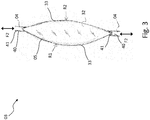
- the at least one mechanically deformable optical element 03 may be as in FIG Fig. 1 and Fig. 2 represented by at least one reflector 31 and / or as in Fig. 3 and Fig. 4 represented by at least one reversibly stretchable and / or compressible lens 32 act.
- the at least one mechanically deformable optical element 03 is at least one optical disc and / or holographic plate or a holographic film or optical disc arranged in the beam path between at least one light source 02 of the illuminant 01 and a lens of a vehicle light housing the illuminant 01 a holographic foil or the like.
- Holography can be used in particular for the guidance of light or generally electromagnetic radiation and can therefore be used in particular also in vehicle lights used.
- the mechanical deformation of the optical element 03 may provide, for example, that the optical element 03 as on in Fig. 1 and Fig. 2 represented example of a designed as a flexible reflector 31 mechanically deformable optical element 03 is reversibly bent by the action of the control element 04.
- the flexurally rigid, reversibly flexible reflector 31 undergoes a bending stress when it is deflected by the action of the control element 04 from a ground state forming, for example in Fig. 1 shown basic position in a bending state forming, for example in Fig. 2 shown mechanically bent bending position is deformed.
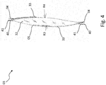
- the mechanical deformation may provide that the optical element 03 as at Fig. 3 and Fig. 4 illustrated example of a designed as a reversible stretchable and compressible lens 32 mechanically deformable optical element 03 by the action of a side of the lens 32 arranged adjusting element 04 or as in Fig. 3 and Fig. 4 shown by, for example, at two or more evenly distributed over the circumference of the lens 32 circumferentially arranged oppositely disposed adjusting elements 04 stretched and / or compressed.
- the reversibly stretchable and compressible lens 32 in this case experiences a tensile and / or a compressive load, which it encounters by slimming or thickening.
- a mechanically undeformed ground state as in Fig. 3 provided thicker shape of the lens 32 provide, whereas a mechanically deformed strain state as in Fig. 4 shown, slimmer shape of the lens 32 may provide, which the lens 32 under tensile stress by or the adjusting elements 04 occupies.
- the lens 32 assumes an undeformed ground state in an intermediate position.
- the lens 32 takes a in Fig. 3 illustrated compression state under a pressure generated by the one or more adjusting elements 04 and a pressure in Fig. 4 shown strain state under a generated by the or the adjusting elements 04 tensile stress.
- Fig. 3 and Fig. 4 each show a sectional view of an embodiment with a correspondingly reversibly stretchable and compressible lens 32, which by means of the edge of the lens 32 at two or more evenly distributed over its circumference arranged peripheral positions oppositely mounted adjusting elements 04 in shape, in particular in its thickness and thus the Curvature of their opposite, optically effective surfaces 33 can be changed.
- various curvatures may be provided on the opposite, optically effective surfaces 33 of the lens, as in FIG Fig. 3 and Fig. 4 indicated by different radii arrows R1, R2, R3, R4.
- the opposing, optically effective surfaces 33 of the lens 32 in the example in Fig. 3 illustrated ground state and / or im in Fig. 4 shown expansion state in each case the same curvatures corresponding to identical, by the arrows R1 and R2 in Fig. 3 shown radii or correspondingly identical, by the arrows R3 and R4 in Fig. 4 have shown radii.
- lens materials for such a reversibly stretchable and compressible lens 32 for example silicones can be used.
- At least one light source 02 of the light source 01 come due to the input described advantages preferably one or more LEDs 20 are used.
- At least one mechanically deformable optical element 03 of the illuminant 01 may additionally comprise an OLED 05 or be covered by an OLED 05.
- the OLED 05 in turn can contribute to the fulfillment of the same light function as the light source 02, or fulfill another light function or contribute accordingly.
- a specular surface of a flexible OLED 05 fabricated using a flexible substrate and flexible encapsulant may form a flexible reflector 32 as a mechanically deformable optical element 03, as exemplified in FIG Fig. 1 and Fig. 2 is shown.
- the metallic, reflective surfaces of OLEDs 05 with flexible substrate and flexible encapsulation can be used as reversibly flexible reflectors 31.
- the illuminant 01 consists of a flexible reflector 31 formed by a flexible OLED 05 as a mechanically deformable optical element 03, which is illuminated by a different light source 02 than the OLED 05, for example an LED 20, in the sense that the other light source 02 their light radiates into the flexible reflector 31 formed by the flexible OLED 05, which forms a variable, predetermined light distribution for this light, depending on the instantaneous deformation by at least one control element 04.
- the flexible OLED 05 used as a flexible reflector 31 can emit even light which can either contribute to a different light function or the same light function as that produced by the other light source 02, for example for the purpose of generating a dynamic light function or for highlighting in the frame an adaptive light function.
- segmented OLEDs 05 with segments which can be controlled individually for light emission, which can compensate for luminance differences on the reflector 31, for example, whereby the emission of the reflector 31 can be homogenized.
- a reflector-like arranged and provided as a flexible reflector 31 as a mechanically deformable optical element 03, flexible OLED 05 may advantageously be provided with a diffuser element, such as a scattering film and / or with a variety of micro-optics, for example on the outermost layer of an OLED 05.
- a diffuser element such as a scattering film and / or with a variety of micro-optics, for example on the outermost layer of an OLED 05.
- a transparent, flexible OLED 05 which is embodied as a reversibly deformable lens 32, may be integrated, for example, by forming its encapsulation, which is made, for example, of plastic and / or other materials, together with a first optically active surface 33 of the lens 32 forming flexible substrate of the OLED 05 a lens shape, for example, as in Fig. 3 and in Fig. 4 shown on one of the OLED 05 opposite, second optically active surface 33 of the lens 32 form.
- the color location of the light source 02 can thereby be corrected.
- the color location of the light source 02 which is preferably formed by an LED 20, changes the optical element 03, for example as in FIG Fig. 3 and Fig. 4
- the embedded OLED 05 can influence the color location of the overall emission by color mixing.
- a temperature-controlled color shift of the LED 20 taking place by the action of the operating temperature and / or the ambient temperature can be compensated for by the radiated matched OLED dominant wavelength.
- legal color locations can be maintained under certain conditions, for example.
- segmented OLEDs which, for example, can compensate for luminance differences in the lens 32, as a result of which the radiation from the lens 32 can become homogeneous.
- an OLED 05 may also be provided, in particular in conjunction with lenses and / or reflectors.
- luminous excitable material can be used on a flexible surface, such as quantum dots (QD).
- QD quantum dots
- the at least one adjusting element 04 is preferably a stroke and / or adjusting device which is controlled according to the adjusting travel along an actuating element axis and which can be shortened and which retracts an assumed extent along, for example, an actuating element axis against Direction of the actuator axis acting, in Fig. 1 and in Fig. 3 by double arrows F1, F2 indicated pressure and preferably also tensile forces holds until the at least one control element 04 driven by its actuation or actuation of the drive driven driven occupies a new extension along the actuator axis.
- an adjusting element 04 may be an electromechanical lifting cylinder or an electromechanical lifting column also called a telescopic column or telescopic drive. These have an electrical drive acting directly on the travel.
- a drive for an actuating element 04 is for example a linear drive in question.
- a linear drive refers to a drive, which leads to a translational movement in a straight line or along another predetermined course.
- Simple embodiments of linear drives are, for example, hydraulic and / or pneumatic cylinders.
- linear drives examples include ball screws, roller screws, such as roller screws with roller return or planetary roller, rack and pinion, electromechanical linear actuators, such as linear motors with electrodynamic operating principle, linear actuators with piezoelectric, electrostatic, electromagnetic, magnetorestrictive or thermoelectric operating principle.
- the at least one adjusting element 04 can alternatively or additionally be designed as a pneumatic and / or hydraulic cylinder.
- a gaseous or liquid fluid such as air or hydraulic oil, also be pressurized by means of an electrically driven pump.
- an influence on the travel is produced only indirectly via the fluid, which flows in and / or out of the valve element controlled as a pneumatic and / or hydraulic cylinder and thereby influences its travel.
- the at least one adjusting element 04 can be embodied as a hydraulic and / or pneumatic cylinder which can be pressurized on one or both sides with pressure.
- the maximum travel of the adjusting element 04 can be increased by a series connection of several linear drives, as is realized for example in telescopic columns.
- the at least one actuating element 04 acting on at least one mechanically deformable optical element 03 for purposes of influencing the light distribution of the light interacting with the optical element 03 and emitted by the light source 02 of the illuminant 01 by means of mechanical deformation is preferably a linear actuator 40.
- a piezoactuator 41 comprises a head and a foot part and a piezoelectric element arranged between the top and bottom part of a plurality of piezoelectric layers stacked one above the other and each forming a linear drive with a small travel.
- the piezoelectric element is constructed by using a material having a suitable crystal structure for the piezoelectric layers so that upon application of an external voltage, a mechanical reaction of the piezoelectric element takes place, which depending on the crystal structure and the contact areas of the electrical voltage, a pressure or a train in a predeterminable Represents direction.
- the piezoelectric element consists of a large number of stacked piezoelectric layers, between each of which an internal electrode of alternating polarity is located. On two opposite side surfaces are external electrodes via which the internal electrodes are supplied with electrical charge. Each inner electrode is connected to the respectively associated outer electrode. In order to avoid a short circuit between the outer electrodes, the inner electrodes must not occupy or cover the entire cross-sectional area of the piezoelectric element, but must maintain a certain distance from the outer electrode of the opposite polarity. In this case, the shape of the surface to be omitted depends on which regions of the circumference of the piezoelectric element are covered by the external electrodes.
- the piezoelectric actuator 41 may be at least partially surrounded by a holding body. Head and foot are on the one hand connected to the mechanically deformable optical element 03 and on the other hand with a formed for example by a conductor carrier 06 base support of the lamp 01 or, for example, a luminaire housing a lamp housing the light source connected, for example articulated, so that by applying a voltage to the piezoelectric actuator 41st For example, the mechanically deformable optical element 03 is compressed, stretched and / or bent.
- a mechanically deformable optical element 03 may alternatively be realized by a plurality of inherently rigid, relatively pivotally arranged Optikissepartien, for example, mirror parts or lens parts whose pivotal positions or their absolute and relative positions are each variable by at least one control element 04.
- the luminous means may comprise a conductor carrier 06.
- a conductor carrier 06 comes as a conductor carrier 06 a short as a printed circuit board, board or printed circuit board (PCB) referred to printed circuit board used.
- Embodiments in which the mechanically deformable optical element 03 can be fixed on one side to a conductor carrier 06 forming, for example, a base carrier of the illuminant 01 can alternatively be embodied as injection-molded circuit carriers produced in MID technology (MID technology: Molded interconnect device technology) ,
- the luminous means 01 provides for the generation of a dynamic and / or adaptive and / or active light effect by means of an optical deformation of an optical element 03 arranged in the beam path of the light emitted by a light source 02 of a luminous means 01, by actuation of an actuating element 04 which mechanical deformation is a change of the by the optical element 03 by its interaction with that of the light source 02 emitted light distribution light distribution 10, 11 entails.
- Fig. 5 shows, for example, a light distribution 10 of a mechanically deformable optical element 03 in a basic position in a mechanically undeformed ground state
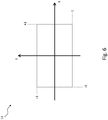
- Fig. 6 shows by way of example a light distribution 11 of a mechanically deformable optical element 03 in a deformation position in a mechanically deformed deformation state.
- X denotes the horizontal propagation of the light distribution while looking against the light propagation of the light previously interacting with the optical element 03
- Y denotes the vertical propagation of the light distribution
- the in Fig. 5 dimensionless illustrated light distribution 10 in the ground state has a much narrower spread ⁇ 1 in both the horizontal and in the vertical direction than the in Fig. 6 illustrated light distribution 11 in the deformation state, which in each axial direction in each case reaches the dimensionless value 1.
- an active light function can be realized by switching back and forth between the ground and deformation states depending on the presence of objects to be illuminated and / or shaded in the further course of the road.
- the light source 01 may, in conjunction with a vehicle lamp with a substantially of a lamp housing and a lens at least partially enclosed luminaire interior be realized.
- the light source 01 is in this case at least partially housed in the interior of the lamp.
- the light source serves to fulfill or contribute to a dynamic and / or an adaptive and / or an active light function of the vehicle light.
- the vehicle lamp may include additional bulbs, as implemented at the outset, which are provided for realizing light functions other than those at least partially fulfilled by the light source 01 with mechanically deformable optical element 03 and for this purpose can be accommodated, for example, in separate chambers formed in the interior of the lamp.
- the invention is an adaptive mirror and / or lens system in order, for example, to realize a multifunctional lighting chamber and / or to compensate for tolerances. Such compensation of tolerances can also be made on a fully assembled assembly, such as a taillight.
- the optical system can be readjusted or calibrated, for example, by comparison with an angle-dependent light intensity and / or luminance measurement.
- flexible or OLEDs 05 can additionally or alternatively be used in one or more directions, if appropriate also with a transparent property.
- such an OLED 05 may also emit light in multiple colors. This property can be realized by a so-called multiple stack, wherein several active, stimulable to light radiation layers are provided in the OLED structure, of which emit at least two light of different colors. With such a structured OLED 05 several light functions of a vehicle lamp can be operated.
- color location tolerances can also be at least partially corrected by, for example, adjusting the color mixture of the light source 02 interacting with the optical element 03, preferably embodied as LED 20, on a reflector-like OLED 05.
- the color location of a multicolor radiating OLED for example controlled by a corresponding sensor in a control circuit, could be readjusted depending on the temperature.
- advantages result from the fact that, depending on the deformation of the optical element or elements 03, light functions can be better illuminated in the sense that they fulfill, for example, a desired light distribution or multiple desired light distributions.
- the invention thus makes it possible, in addition to a complete solution of the task, to realize an adaptive and active optics for light systems used in vehicle lights.
- Adaptive and active optics are techniques that improve the quality of optical systems and at least reduce or compensate errors as much as possible. As a rule, this is done by movement or deformation of mirrors. Such measures are known above all from astronomy in the field of mirror telescopes.
- the illuminant 01 may alternatively or additionally comprise individual or a combination of several in the context of the prior art and / or in one or more of the documents mentioned in the prior art and / or features mentioned in the preceding description.
- the invention is particularly industrially applicable in the field of manufacturing vehicle lights, in particular motor vehicle lights.
Abstract
Es werden ein Leuchtmittel (01) mit mindestens einer Lichtquelle (02) und wenigstens einem im Strahlengang des von der Lichtquelle (02) abgestrahlten Lichts angeordneten, zur Ausformung einer vorgegebenen Lichtverteilung beitragenden Optikelement (03) zur Lichtlenkung und eine Fahrzeugleuchte beschrieben. Das Leuchtmittel (01) zeichnet sich dadurch aus, dass zumindest ein Optikelement (03, 31, 32) des Leuchtmittels (01) mechanisch verformbar ist, und das Leuchtmittel (01) mindestens ein auf das mindestens eine mechanisch verformbare Optikelement (03, 31, 32) einwirkendes Stellelement (04) umfasst, bei dessen Betätigung eine mechanische Verformung des Optikelements (03, 31, 32) einhergehend mit einer Veränderung der durch das betreffende Optikelement (03, 31, 32) ausgeformten Lichtverteilung (51, 52) erfolgt. Die Fahrzeugleuchte weist einen von einem Leuchtengehäuse und einer Lichtscheibe zumindest teilweise umschlossenen Leuchteninnenraum auf, der mindestens ein voranstehend beschriebenes Leuchtmittel (01) zumindest teilweise beherbergt.A luminous means (01) having at least one light source (02) and at least one optical element (03) for directing the light and a vehicle lamp which is arranged in the beam path of the light emitted by the light source (02) and which contributes to the shaping of a predetermined light distribution are described. The luminous means (01) is characterized in that at least one optical element (03, 31, 32) of the luminous means (01) is mechanically deformable, and the luminous means (01) at least one on the at least one mechanically deformable optical element (03, 31, 32) acting actuator (04), upon actuation of a mechanical deformation of the optical element (03, 31, 32), accompanied by a change in the formed by the relevant optical element (03, 31, 32) light distribution (51, 52). The vehicle lamp has a luminaire housing which is at least partially enclosed by a luminaire housing and a lens and at least partially accommodates at least one illuminant (01) described above.
Description
Die Erfindung betrifft ein Leuchtmittel gemäß dem Oberbegriff des Anspruchs 1 und eine Fahrzeugleuchte gemäß dem Oberbegriff des Anspruchs 10.The invention relates to a lighting device according to the preamble of
Insbesondere betrifft die Erfindung ein zur Erfüllung einer dynamischen und/oder einer adaptiven Lichtfunktion einer Fahrzeugleuchte vorgesehenes oder einer vorgeschriebenen Lichtverteilung einer solchen Lichtfunktion beitragendes Leuchtmittel mit mindestens einer Lichtquelle und einem in deren Strahlengang angeordneten mechanisch verformbaren Optikelement, sowie eine vermittels eines entsprechenden zur Erfüllung einer dynamischen und/oder einer adaptiven und/oder einer aktiven Lichtfunktion vorgesehenen oder hierzu beitragenden Leuchtmittels ausgerüstete Fahrzeugleuchte.In particular, the invention relates to a for providing a dynamic and / or adaptive light function of a vehicle lamp provided or a prescribed light distribution of such a light function contributing lamp with at least one light source and arranged in the beam path mechanically deformable optical element, and by means of a corresponding to fulfill a dynamic and / or a vehicle light provided with an adaptive and / or an active light function or provided for this purpose.
Eine Fahrzeugleuchte umfasst beispielsweise einen im Wesentlichen von einem Leuchtengehäuse und einer Lichtscheibe umschlossenen Leuchteninnenraum und mindestens ein gegebenenfalls zumindest zum Teil darin beherbergtes, mindestens eine Lichtquelle umfassendes Leuchtmittel für wenigstens eine Lichtfunktion der Fahrzeugleuchte.A vehicle lamp comprises, for example, a luminaire interior substantially enclosed by a luminaire housing and a lens, and at least one illuminant for at least one light function of the vehicle luminaire, comprising at least one optionally at least partially housed therein, comprising at least one light source.
Beispiele für Fahrzeugleuchten sind am Fahrzeugbug, an den Fahrzeugflanken und/oder an den Seitenspiegeln sowie am Fahrzeugheck angeordnete Wiederholblinkleuchten, Ausstiegsleuchten, beispielsweise zur Umfeldbeleuchtung, Begrenzungsleuchten, Bremsleuchten, Nebelleuchten, Rückfahrleuchten, sowie typischerweise hoch gesetzte dritte Bremsleuchten, so genannte Central, High-Mounted Braking Lights, Tagfahrleuchten, Scheinwerfer und auch als Abbiege- oder Kurvenlicht verwendete Nebelscheinwerfer, sowie Kombinationen hiervon.Examples of vehicle lights are the Fahrzeugbug, on the vehicle flanks and / or on the side mirrors and arranged at the rear of vehicle rear lights, exit lights, such as ambient lighting, marker lights, brake lights, fog lamps, reversing lights, and typically high set third brake lights, so-called Central, High-Mounted Braking lights, daytime running lights, headlamps and fog lights used as turning or cornering lights, as well as combinations thereof.
Eine solche Kombination ist beispielsweise regelmäßig in den bekannten Heckleuchten verwirklicht. In diesen kommen beispielsweise Wiederholblinkleuchten, Begrenzungsleuchten, Bremsleuchten, Nebelleuchten sowie Rückfahrleuchten zum Einsatz, um nur eine von vielen in Heckleuchten verwirklichten Kombinationen zu nennen. Weder erhebt diese Aufzählung Anspruch auf Vollständigkeit, noch bedeutet dies, dass in einer Heckleuchte alle genannten Leuchten kombiniert werden müssen. So können beispielsweise auch nur zwei oder drei der genannten oder auch anderer Leuchten in einem gemeinsamen Leuchtengehäuse einer Heckleuchte miteinander kombiniert sein.Such a combination is realized, for example, regularly in the known taillights. These include, for example, repeating flashing lights, marker lights, brake lights, fog lights and reversing lights are used to name just one of many realized in tail lights combinations. Neither does this enumeration claim to be complete, nor does this mean that in a tail light all the aforementioned lights must be combined. So For example, only two or three of the mentioned or else other luminaires can be combined with one another in a common luminaire housing of a taillight.
Jede Fahrzeugleuchte erfüllt je nach Ausgestaltung eine oder mehrere Aufgaben beziehungsweise Funktionen. Zur Erfüllung jeder Aufgabe beziehungsweise Funktion ist eine Lichtfunktion der Fahrzeugleuchte vorgesehen. Lichtfunktionen sind beispielsweise bei einer Ausgestaltung als Scheinwerfer eine die Fahrbahn ausleuchtende Funktion, oder bei einer Ausgestaltung als Signalleuchte eine Signalfunktion, wie beispielsweise eine Wiederholblinklichtfunktion zur Fahrtrichtungsanzeige oder eine Bremslichtfunktion zur Anzeige einer Bremstätigkeit, oder z.B. einer Begrenzungslichtfunktion, wie etwa einer Rücklichtfunktion, zur Sicherstellung einer Sichtbarkeit des Fahrzeugs bei Tag und/oder Nacht, wie etwa bei einer Ausgestaltung als Heckleuchte oder Tagfahrleuchte.Depending on the design, each vehicle lamp fulfills one or more tasks or functions. To fulfill each task or function, a light function of the vehicle lamp is provided. Light functions are, for example, in a configuration as a headlamp a function illuminating the road surface, or in a configuration as a signal light, a signal function, such as a Wiederblinklichtfunktion to the direction indicator or a brake light function to indicate a braking action, or. a limiting light function, such as a taillight function, to ensure visibility of the vehicle during the day and / or night, such as in a taillight or daytime running light configuration.
Jede Lichtfunktion muss dabei eine beispielsweise gesetzlich vorgegebene Lichtverteilung erfüllen. Die Lichtverteilung legt dabei mindestens einzuhaltende, umgangssprachlich als Helligkeit bezeichnete Lichtströme in zumindest einzuhaltenden Raumwinkelbereichen fest. Je höher dabei die Helligkeit ist, um so weiter trägt die Lichtfunktion beziehungsweise um so größer ist die kurz als Sichtweite bezeichnete Entfernung, aus der sie wahrgenommen werden kann.Each light function must fulfill an example prescribed by law light distribution. The light distribution sets at least to be observed, colloquially known as brightness luminous flux in at least to be observed solid angle ranges. The higher the brightness, the farther the light function contributes, or the greater is the distance, briefly called the range of sight, from which it can be perceived.
Für die einzelnen Lichtfunktionen sind zum Teil unterschiedliche, Helligkeiten beziehungsweise Sichtweiten festlegende Lichtstärken sowie zum Teil unterschiedliche Lichtfarben und Leuchtflächengrößen vorgegeben.For the individual lighting functions, in some cases different light intensities, determining brightnesses or visibility, as well as, in part, different light colors and luminous surface sizes are specified.
Aufgrund ihres hohen Wirkungsgrads bei der Umwandlung von elektrischem Strom in für das menschliche Auge sichtbares Licht kommen als Lichtquellen von Leuchtmitteln für Fahrzeugleuchten vermehrt Halbleiterlichtquellen zum Einsatz, allen voran anorganische Leuchtdioden sowie in wenigen Fahrzeugmodellen auch bereits organische Leuchtdioden.Due to their high efficiency in the conversion of electric current in visible to the human eye light come as light sources of bulbs for vehicle lights increasingly semiconductor light sources used, especially inorganic light emitting diodes and in a few vehicle models already organic light-emitting diodes.
Anorganische Leuchtdioden bestehen aus mindestens einem Lichtemittierende-Diode-Halbleiter-Chip, kurz LED-Chip, sowie wenigstens einer beispielsweise durch Spritzgießen angeformten, den mindestens einen LED-Chip ganz oder teilweise umhüllenden Primäroptik. Auch sind Fahrzeugleuchten bekannt, in denen reine LED-Chips ohne angeformte Primäroptiken zum Einsatz kommen.Inorganic light emitting diodes consist of at least one light emitting diode semiconductor chip, short LED chip, and at least one, for example, molded by injection molding, the at least one LED chip completely or partially enveloping primary optics. Vehicle lights are also known in which pure LED chips are used without molded primary optics.
Im Folgenden wird deshalb der Einfachheit halber nicht mehr zwischen anorganischer Leuchtdiode und LED-Chip unterschieden und statt dessen einheitlich der Begriff LED stellvertretend für beides verwendet, es sei denn, es ist explizit etwas anderes erwähnt.In the following, therefore, for the sake of simplicity, no distinction is made between inorganic light-emitting diode and LED chip and instead the term LED is used uniformly for both, unless explicitly stated otherwise.
Eine kurz als OLED (Organic Light Emitting Diode; OLED) bezeichnete organische Leuchtdiode ist ein leuchtendes Dünnschichtbauelement aus organischen halbleitenden Materialien mit mindestens einer zwischen elektrisch leitenden, beispielsweise metallischen Schichten für Anode und Kathode eingeschlossen Emitterschicht. Die Stärke oder anders ausgedrückt Dicke der Schichten liegt in einer Größenordnung von etwa 100 nm. Typischerweise beträgt sie je nach Aufbau 100 nm bis 500 nm.An organic light-emitting diode (OLED) is a luminous thin-film component made of organic semiconducting materials with at least one emitter layer enclosed between electrically conductive, for example metallic layers for anode and cathode. The thickness or, in other words, the thickness of the layers is on the order of about 100 nm. Typically, depending on the structure, it is 100 nm to 500 nm.
Die Schichten einer OLED sind nacheinander auf ein Substrat aufgebracht, welches gemeinsam mit einer auf die oberste Schicht aufgebrachten Verkapselung die Schichten der OLED gegen Wasser, Sauerstoff sowie gegen andere Umwelteinflüsse, wie etwa Kratzbeschädigung und/oder Druckbelastung schützt.The layers of an OLED are successively applied to a substrate which, together with an encapsulation applied to the uppermost layer, protects the layers of the OLED against water, oxygen and against other environmental influences, such as scratch damage and / or pressure loading.
Im Unterschied zu anorganischen Leuchtdioden benötigen OLEDs keine einkristallinen Materialien. Im Vergleich zu LEDs lassen sich OLEDs daher in kostengünstiger Dünnschichttechnik herstellen. OLEDs ermöglichen dadurch die Herstellung flächiger Lichtquellen, die einerseits sehr dünn und andererseits als durch die Lichtscheibe einer Fahrzeugleuchte hindurch sichtbare leuchtende Fläche eingesetzt einen besonders homogenes Erscheinungsbild aufweisen.In contrast to inorganic light-emitting diodes, OLEDs do not require monocrystalline materials. Compared to LEDs, OLEDs can therefore be produced using inexpensive thin-film technology. As a result, OLEDs make it possible to produce flat light sources which on the one hand have a very thin appearance and, on the other hand, have a particularly homogeneous appearance when used as a luminous surface visible through the lens of a vehicle lamp.
Allen Halbleiterlichtquellen ist deren schnelles Ansprechen mit dem Beginn eines Stromdurchflusses in Durchlassrichtung gemein, entsprechend deren im Gegensatz beispielsweise zu als Lichtquellen von Leuchtmitteln in Fahrzeugleuchten ebenfalls eingesetzten Glühlampen und Gasentladungslampen quasi verzögerungsfreier, sofortiger Lichtabstrahlung. Darüber hinaus erfolgt die Lichtabstrahlung von Halbleiterlichtquellen quasi sofort in voller Leuchtstärke, wohingegen die Lichtabstrahlung der erwähnten konventionellen Lichtquellen Zeit benötigt, um ihre volle Leuchtstärke vom lichtabstrahlungsfreien Kaltzustand aus zu erreichen. Bei Glühlampen beträgt die Zeit, bis diese ihre volle Leuchtstärke erreichen typischerweise 100ms bis 500ms.All semiconductor light sources whose fast response with the beginning of a current flow in the forward direction common, according to their in contrast, for example, as light sources of bulbs in vehicle lights also used incandescent and gas discharge lamps quasi delay-free, immediate light emission. In addition, the light emission of semiconductor light sources takes place almost immediately in full luminosity, whereas the light emission of the mentioned conventional light sources takes time to reach their full luminosity from the light emission-free cold state. For incandescent lamps, the time until they reach their full luminosity is typically 100ms to 500ms.
Um die Wahrnehmbarkeit beziehungsweise Wahrnehmungskraft von Lichtfunktionen einer Fahrzeugleuchte für andere Verkehrsteilnehmer zu erhöhen ist bekannt, diese innerhalb der gesetzlich zugelassenen Grenzen für einen visuell auffallenden Effekt durch eine gezielte Ansteuerung zu animieren und dadurch aufleben zu lassen, wodurch die entsprechende Lichtfunktion und damit deren Signalwirkung durch andere Verkehrsteilnehmer schneller wahrgenommen wird.In order to increase the perceptibility or perceptual power of light functions of a vehicle lamp for other road users is known to animate within the legally permitted limits for a visually striking effect by a targeted control and thereby revive, creating the corresponding light function and thus their signal effect by others Road users is perceived faster.
Ein bekanntes Beispiel sind so genannte dynamische Lichtfunktionen, bei denen die vom Gesetzgeber eingeräumte Zeit, die eine Glühlampe als eine gesetzlich erlaubte Lichtquelle eines zur Erfüllung einer Lichtfunktion vorgesehenen Leuchtmittels benötigt, um ihre volle Leuchtstärke zu erreichen, genutzt wird, um einen visuellen Effekt zu erzielen.A well-known example is so-called dynamic lighting functions, in which the time allowed by law, which requires an incandescent lamp as a legally permitted light source of a light intended to fulfill a light function to reach its full luminosity, is used to achieve a visual effect ,
Ein Beispiel eines solchen visuellen Effekts ist das Wischen in Richtung der Richtung einer beabsichtigten Fahrtrichtungsanzeige bei einer Wiederholblinklichtfunktion eines Fahrtrichtungsanzeigers.An example of such a visual effect is the wiping in the direction of the direction of an intended turn signal in a re-turn light function of a turn signal.
Eine solche dynamische Lichtfunktion wird beispielsweise durch ein Leuchtmittel mit mehreren, nacheinander der Reihe nach angehenden LEDs als Lichtquellen verwirklicht.Such a dynamic light function is realized, for example, by means of a light source with a plurality of successive successive LEDs as light sources.
Untersuchungen haben gezeigt, dass hierdurch die Verkehrssicherheit erhöht wird, da durch das Wischen bereits mit Beginn der Wahrnehmung der Lichtfunktion durch andere Verkehrsteilnehmer die durch die Lichtfunktion angezeigte beabsichtigte Fahrtrichtungsänderung erkannt wird.Investigations have shown that this increases the traffic safety, since by wiping already at the beginning of the perception of the light function by other road users the intended change of direction indicated by the light function is detected.
Ferner ist bekannt, dass Leuchtanzeigen, beispielsweise in einem Armaturenbrett eines Fahrzeugs angezeigte Warnanzeigen, die mit ihrem Aufleuchten dem Betrachter entgegen zu springen scheinen, durch ihre scheinbare Bewegung auf den Betrachter zu von diesem besonders gut wahrgenommen werden und diesen alarmieren, auch wenn dessen Blick nicht unmittelbar auf einen Bereich gerichtet ist, in dem die Warnanzeige angezeigt wird. Sie haben daher eine erhöhte Wahrnehmungskraft zur Folge.Furthermore, it is known that illuminated displays, for example, warning displays displayed in a dashboard of a vehicle that seem to jump towards the viewer with their illumination are perceived by its apparent movement to the viewer of this particularly well and alert him, even if his view is not is aimed directly at an area in which the warning display is displayed. They therefore result in an increased power of perception.
Um die Wahrnehmbarkeit beziehungsweise Wahrnehmungskraft von Lichtfunktionen einer Fahrzeugleuchte für andere Verkehrsteilnehmer zu erhöhen ist darüber hinaus bekannt, diese situationsbezogen hervorzuheben.In order to increase the perceptibility or perceptual power of light functions of a vehicle lamp for other road users is also known to emphasize this situation.
Eine solche situationsbezogene Hervorhebung ist insbesondere bei Heckleuchten in Form so genannter adaptiver Lichtfunktionen anzutreffen.Such situation-related emphasis is found especially in tail lights in the form of so-called adaptive lighting functions.
Eine adaptive Lichtfunktion erfüllt eine über deren vorgesehene, normale Funktion der Lichtfunktion hinausgehende, gegebenenfalls zusätzliche, die vorgesehene, normale Funktion hervorhebende und/oder ergänzende Funktion.An adaptive light function fulfills a function which goes beyond its intended, normal function of the light function and, if necessary, additionally emphasizes and / or supplements the intended, normal function and / or supplementary function.
Ein prominentes Beispiel ist eine von einzelnen Herstellern auch aktives Bremslicht oder dynamisches Bremslicht genannte adaptive Bremslichtfunktion.A prominent example is one of individual manufacturers also active brake light or dynamic brake light called adaptive brake light function.
Adaptiv ist in diesem Zusammenhang als in mindestens zwei Eskalationsstufen anpassungsfähig zu verstehen, im Fall einer Bremslichtfunktion meistens zweistufig.In this context, adaptive is to be understood as adaptable in at least two escalation stages, in most cases two-stage in the case of a brake light function.
Deren über die normale Funktion eines bestimmungsgemäßen Aufleuchtens der Bremslichtfunktion bei Betätigung der Betriebsbremse hinausgehende Funktion liegt in einer Information nachfolgender Verkehrsteilnehmer über die Stärke der vom vorausfahrenden Fahrzeug ausgeführten Bremsung durch zusätzliche Hervorhebung der Bremslichtfunktion. Dabei wird die adaptive Bremslichtfunktion nicht nur verwendet, um eine Bereitschaft oder Betätigung der Betriebsbremse anzuzeigen, was wie bei einer herkömmlichen Bremslichtfunktion durch deren bestimmungsgemäßes Aufleuchten ab einem leichten Niederdrücken des Bremspedals erfolgt, sondern zusätzlich, um den nachfolgenden Verkehr über die Stärke und/oder Plötzlichkeit der Bremsung zu informieren, was beispielsweise durch Hinzufügen zusätzlicher Leuchtflächen und damit einhergehend Vergrößerung der bei aktiver Bremslichtfunktion aufleuchtenden Leuchtfläche beispielsweise oberhalb eines Schwellenwerts des vermittels des Bremspedals aufgebrachten Bremsdrucks und/oder beispielsweise oberhalb eines Schwellenwerts der Betätigungsgeschwindigkeit des Bremspedals erfolgen kann. Eine solche adaptive Bremslichtfunktion unterscheidet nicht zwischen einer normalen Betätigung der Betriebsbremse und einer Notbremsung, sondern lediglich zwischen leichter und starker Betätigung der Betriebsbremse. Bei letzterer muss es sich demnach nicht unbedingt um eine Notbremsung handeln. Bei normaler Betätigung der Betriebsbremse leuchtet eine Leuchtfläche einer Heckleuchte je Seite des Fahrzeugs auf. Bei einer starken und/oder plötzlichen Betätigung der Betriebsbremse leuchten je zwei Leuchtflächen einer Heckleuchte je Seite des Fahrzeugs auf. Dabei handelt es sich typischerweise um die bei Erfüllung der normalen Bremslichtfunktion aufleuchtende Leuchtfläche sowie um eine zusätzliche Leuchtfläche, beispielsweise zusätzlich um die Leuchtfläche der Nebelschlusslichtfunktion an beiden Seiten. Alternativ oder zusätzlich können alle in einer höchsten Eskalationsstufe einer adaptiven Bremslichtfunktion aktiven Leuchtflächen deutlich heller als bei einer normalen Betätigung der Betriebsbremse leuchten.Whose beyond the normal function of a proper lighting of the brake light function when operating the service brake function is in an information subsequent traffic participants on the strength of the executed by the vehicle ahead braking by additional emphasis of the brake light function. In this case, the adaptive brake light function is not only used to indicate a readiness or actuation of the service brake, which is done as in a conventional brake light function by their intended lighting from a slight depression of the brake pedal, but in addition to the subsequent traffic on the strength and / or suddenness to inform the brake, which can be done for example by adding additional luminous surfaces and concomitantly increase the illuminating when the brake light function illuminated area, for example, above a threshold of the means of the brake pedal applied brake pressure and / or for example above a threshold value of the operating speed of the brake pedal. Such an adaptive brake light function does not distinguish between a normal operation of the service brake and an emergency brake, but only between light and strong operation of the service brake. The latter does not necessarily mean emergency braking. During normal operation of the service brake, a lighting area of a tail light lights up on each side of the vehicle. In the event of a strong and / or sudden actuation of the service brake, two lighting surfaces of one tail light illuminate on each side of the vehicle. These are typically the illuminating surface that lights up when the normal brake light function is fulfilled, and an additional luminous area, for example, the additional one Illuminated area of the rear fog light function on both sides. Alternatively or additionally, all luminous surfaces which are active in a highest escalation stage of an adaptive brake light function can shine much brighter than in the case of a normal actuation of the service brake.
Zur Verwirklichung einer adaptiven Bremslichtfumktion mit Notbremsungserkennung ist beispielsweise bekannt, anhand des Bremsdrucks, der Betätigungsgeschwindigkeit des Bremspedals, der Fahrgeschwindigkeit, dem Vergleich der vermittels eines Beschleunigungssensors ermittelten tatsächlichen und der anhand eines Bremsdrucksensors ermittelten gewünschten Verzögerung, der Haftreibung zwischen Reifen und Fahrbahn, der Aktivierung von Bremsassistenzfunktionen, wie etwa einem Antiblockiersystem (ABS), einem elektronischen Stabilitätsprogramm (ESP) und/oder einem umgebungsüberwachenden Notbremssystem, eine Gefahrensituation zu erkennen und im Fall deren Auftretens eine Aktivierung der Bremslichtfunktion sowie zusätzlich oder alternativ bei bereits aktiver Bremslichtfunktion deren Hervorhebung zu veranlassen.To realize an adaptive Bremslichtfumktion with emergency braking detection is known, for example, based on the brake pressure, the operating speed of the brake pedal, the vehicle speed, the comparison of the determined by means of an acceleration sensor actual and determined using a brake pressure sensor desired delay, the friction between tires and road, the activation of Brake assist functions, such as an anti-lock braking system (ABS), an electronic stability program (ESP) and / or an environment-monitoring emergency braking system to detect a dangerous situation and to cause their activation an activation of the brake light function and additionally or alternatively with already active brake light function their emphasis.
Dabei gibt es verschiedene Arten der Hervorhebung von adaptiven Bremslichtfunktionen beziehungsweise Notbremsanzeigen.There are different ways of highlighting adaptive brake light functions or emergency brake displays.
Bei einer adaptiven Bremslichtfunktion mit Notbremserkennung leuchtet die Bremslichtfunktion bei einer normalen Betätigung der Betriebsbremse wie bei jedem anderen Kraftfahrzeug auf. Bei einer Notbremsung können die Bremslichter allerdings mehrmals pro Sekunde blinken. Dadurch wird der nachfolgende Verkehr gewarnt und die Reaktionszeit laut einer Studie verkürzt. Wird bis zum Stillstand gebremst, kann sich anschließend die Warnblinkanlage einschalten, indem an allen am Fahrzeug zur Erfüllung der Wiederholblinklichtfunktion verbauten Fahrzeugleuchten die Wiederholblinklichtfunktion aktiviert wird. Eine Deaktivierung der Warnblinkanlage kann automatisch durch Fortsetzen der Fahrt oder manuell durch Betätigen der Warnblinktaste erfolgen.In an adaptive brake light function with emergency brake detection, the brake light function lights up during normal operation of the service brake as with any other motor vehicle. In emergency braking, however, the brake lights may flash several times per second. As a result, the following traffic is warned and the reaction time is shortened according to a study. If it is braked to a standstill, the hazard warning lights can then turn on by activating the repeatable flashing light function on all the vehicle lights installed on the vehicle to fulfill the repeatable flashing light function. A deactivation of the hazard warning lights can be done automatically by continuing the journey or manually by pressing the warning flash button.
Zusammengefasst ziehen sowohl dynamische Lichtfunktionen, als auch adaptive Lichtfunktionen die Aufmerksamkeit anderer Verkehrsteilnehmer an, sei es durch ein Auflebenlassen anhand einer gezielten Ansteuerung beispielsweise mehrerer Lichtquellen nacheinander, oder durch eine Hervorhebung bestimmungsgemäß verwirklichter Lichtfunktionen. Hierdurch tragen sie einer Verbesserung der Sicht- und Wahrnehmbarkeit von Lichtfunktionen einer Fahrzeugleuchte bei, einhergehend mit einer Steigerung der Verkehrssicherheit.In summary, both dynamic light functions and adaptive light functions attract the attention of other road users, either by being set up by means of targeted activation of, for example, several light sources one after the other, or by highlighting intended light functions. As a result, they contribute to an improvement of the visual and Perceptibility of light functions of a vehicle lamp, along with an increase in traffic safety.
Von Fahrzeugscheinwerfern ist darüber hinaus zur Steigerung der Verkehrssicherheit eine aktive Lichtfunktion zur situationsangepassten Ausleuchtung der Fahrbahn bekannt. Die aktive Lichtfunktion weist eine variable Lichtverteilung auf, die sich den Verkehrs- und Umgebungsbedingungen anpasst, beispielsweise um Objekte im weiteren Fahrbahnverlauf gezielt anzuleuchten,um den Fahrer des eigenen Fahrzeugs auf deren Anwesenheit aufmerksam zu machen, und/oder andere Verkehrsteilnehmer von einer Anstrahlung zur Vermeidung deren Blendung auszunehmen.From vehicle headlamps is also known to increase traffic safety, an active light function for situation-adapted illumination of the road. The active light function has a variable light distribution, which adapts to the traffic and environmental conditions, for example to illuminate objects in the further course of the road specifically to make the driver of the own vehicle aware of their presence, and / or other road users of a radiation to avoid to remove their glare.
Aktive Lichtfunktionen können beispielsweise in einem Fahrzeugscheinwerfer dazu genutzt werden unterschiedliche Ausleuchtungen zu verwirklichen, wie etwa eine Kurvenlichtfunktion, eine Autobahnlichtfunktion, eine blendfreie Fernlichtfunktion oder dergleichen.Active light functions can be used, for example, in a vehicle headlamp to realize different illuminations, such as a cornering light function, a motorway light function, a glare-free high beam function or the like.
Aktive Lichtfunktionen sind bislang durch Leuchtmittel mit einer Vielzahl von einzeln ansteuerbaren, jeweils zu einem anderen Teil zur vorgeschriebenen Lichtverteilung insbesondere einer Abblendlichtfunktion beitragenden Lichtquellen verwirklicht.Active light functions have hitherto been realized by means of light sources having a multiplicity of individually controllable light sources each contributing to a different part to the prescribed light distribution, in particular a dimming light function.
Eine der Erfindung zu Grunde liegende Aufgabe ist die Bereitstellung eines zur Erfüllung wenigstens einer Lichtfunktion einer Fahrzeugleuchte vorgesehenen oder einer vorgeschriebenen Lichtverteilung einer solchen Lichtfunktion beitragenden Leuchtmittels mit zumindest einer Lichtquelle, sowie einer mit einem solchen Leuchtmittel ausgestatteten Fahrzeugleuchte, welche einer erhöhten Verkehrssicherheit beitragen.One object of the invention is to provide a light source for illuminating at least one light function of a vehicle lamp or contributing to a prescribed light distribution of such a light function with at least one light source and a vehicle light equipped with such a light source, which contribute to increased traffic safety.
Die Aufgabe wird jeweils gelöst durch die Merkmale der unabhängigen Ansprüche. Vorteilhafte Ausführungsformen sind in den Ansprüchen, den Zeichnungen sowie in der nachfolgenden Beschreibung, einschließlich der zu den Zeichnungen zugehörigen, wiedergegeben.The object is achieved in each case by the features of the independent claims. Advantageous embodiments are set forth in the claims, the drawings and the following description, including those associated with the drawings.
Ein erster Gegenstand der Erfindung betrifft demnach ein Leuchtmittel zur Erfüllung oder zumindest zum Beitrag zu wenigstens einer vorgeschriebenen Lichtverteilung einer beispielsweise dynamischen und/oder adaptiven und/oder aktiven Lichtfunktion einer Fahrzeugleuchte.A first subject of the invention accordingly relates to a luminous means for fulfilling or at least contributing to at least one prescribed light distribution of, for example, a dynamic and / or adaptive and / or active light function of a vehicle lamp.
Das Leuchtmittel umfasst wenigstens eine Lichtquelle.The lighting means comprises at least one light source.
Wenigstens einer Lichtquelle des Leuchtmittels ist ein oder sind mehrere zur Ausformung einer Lichtverteilung beitragende Optikelemente zur Lichtlenkung zugeordnet.At least one light source of the luminous means is associated with one or more optical elements contributing to the formation of a light distribution for directing the light.
Das oder die Optikelemente sind im Strahlengang des von mindestens einer Lichtquelle des Leuchtmittels abgestrahlten Lichts angeordnet.The one or more optical elements are arranged in the beam path of the light emitted by at least one light source of the light source.
Zumindest ein Optikelement des mindestens einen Optikelements ist mechanisch verformbar.At least one optical element of the at least one optical element is mechanically deformable.
Das Leuchtmittel umfasst darüber hinaus mindestens ein auf das mindestens eine mechanisch verformbare Optikelement einwirkendes Stellelement. Bei einer Betätigung des mindestens einen Stellelements erfolgt eine mechanische Verformung des Optikelements einhergehend mit einer Veränderung der durch das betreffende Optikelement ausgeformten Lichtverteilung.The lighting means further comprises at least one acting on the at least one mechanically deformable optical element actuator. Upon actuation of the at least one actuating element, a mechanical deformation of the optical element takes place accompanied by a change in the light distribution formed by the relevant optical element.
Das Leuchtmittel zeichnet sich demnach dadurch aus, dass mindestens ein im Strahlengang des von wenigstens einer Lichtquelle des Leuchtmittels abgestrahlten Lichts angeordnetes Optikelement mittels zumindest eines Stellelements mechanisch verformbar ist, wodurch dieses eine andere Lichtverteilung ausformt. Die mechanische Verformung hat demnach eine Änderung der Lichtverteilung des mit dem Optikelement 03 wechselwirkenden, beispielsweise durch das Optikelement 03 hindurchtretenden und/oder vermittels des Optikelements 03 umgelenkten Lichts zur Folge.The luminous means is accordingly distinguished by the fact that at least one optical element arranged in the beam path of the light emitted by at least one light source of the luminous means is mechanically deformable by means of at least one adjusting element, whereby this forms a different light distribution. The mechanical deformation accordingly results in a change in the light distribution of the light interacting with the
Die mechanische Verformung sieht beispielsweise vor, dass das Optikelement gestaucht, gedehnt und/oder gebogen wird.The mechanical deformation provides, for example, that the optical element is compressed, stretched and / or bent.
Bei den erwähnten Optikelementen kann es sich um wenigstens einen Reflektor und/oder um mindestens eine Linse und/oder um eine oder mehrere im Strahlengang zwischen wenigstens einer Lichtquelle des Leuchtmittels und einer Lichtscheibe einer das Leuchtmittel beherbergenden Fahrzeugleuchte angeordnete Optikscheiben und/oder holografischen Platten beziehungsweise Filmen beziehungsweise Folien oder dergleichen handeln. Holografie kann insbesondere zur Lenkung von Licht beziehungsweise allgemein elektromagnetischer Strahlung eingesetzt werden und kann daher insbesondere auch in Fahrzeugleuchten zum Einsatz gebracht werden.The optical elements mentioned may be at least one reflector and / or at least one lens and / or one or more optical disks and / or holographic plates or films arranged in the beam path between at least one light source of the luminous means and a lens of a vehicle light housing the luminous means or films or the like act. Holography can be used in particular for the guidance of light or generally electromagnetic radiation and can therefore be used in particular also in vehicle lights used.
Als auf das mindestens eine Optikelement zu Zwecken dessen mechanischer Verformung einwirkende Stellelemente kommen bevorzugt Linearaktoren zum Einsatz.Linear actuators are preferably used as actuating elements acting on the at least one optical element for purposes of its mechanical deformation.
Aufgrund deren linearer Betätigungsrichtung, deren hoher Betätigungsgeschwindigkeit und deren hoher erzielbarer Betätigungsfrequenz sowie deren zwischenzeitlich erprobter, hoher Lebensdauer kommen wegen ihres Aufbaus frei von komplexen beweglichen Bauteilen besonders bevorzugt Piezoaktoren zum Einsatz.Due to their linear actuation direction, their high actuation speed and their high achievable actuation frequency as well as their interim proven, long life come due to their structure free of complex moving components particularly preferred piezo actuators used.
Ein Piezoaktor umfasst ein Kopf- und ein Fußteil sowie ein zwischen Kopf- und Fußteil angeordnetes Piezoelement aus mehreren übereinander gestapelten Piezolagen. Das Piezoelement ist unter Verwendung eines Materials mit einer geeigneten Kristallstruktur für die Piezolagen so aufgebaut, dass bei Anlage einer äußeren Spannung eine mechanische Reaktion des Piezoelements erfolgt, die in Abhängigkeit von der Kristallstruktur und der Anlagebereiche der elektrischen Spannung einen Druck oder einen Zug in eine vorgebbare Richtung darstellt.A piezoelectric actuator comprises a head and a foot part and a piezoelectric element arranged between the top and bottom part and comprising a plurality of piezoelectric layers stacked one above the other. The piezoelectric element is constructed by using a material having a suitable crystal structure for the piezoelectric layers so that upon application of an external voltage, a mechanical reaction of the piezoelectric element takes place, which depending on the crystal structure and the contact areas of the electrical voltage, a pressure or a train in a predeterminable Represents direction.
Das Piezoelement besteht aus einer großen Anzahl von übereinander gestapelten Piezolagen, zwischen denen sich jeweils eine Innenelektrode abwechselnder Polarität befindet. An zwei gegenüberliegenden Seitenflächen befinden sich Außenelektroden über welche die Innenelektroden mit elektrischer Ladung versorgt werden. Jede Innenelektrode ist mit der jeweils zugehörigen Außenelektrode verbunden. Um einen Kurzschluss zwischen den Außenelektroden zu vermeiden, dürfen die Innenelektroden nicht die komplette Querschnittsfläche des Piezoelements einnehmen oder überdecken, sondern müssen von der Außenelektrode der jeweils entgegen gesetzten Polarität einen gewissen Abstand einhalten. Dabei hängt die Form der auszusparenden Fläche davon ab, welche Bereiche des Umfangs des Piezoelements von den Außenelektroden überdeckt sind.The piezoelectric element consists of a large number of stacked piezoelectric layers, between each of which an internal electrode of alternating polarity is located. On two opposite side surfaces are external electrodes via which the internal electrodes are supplied with electrical charge. Each inner electrode is connected to the respectively associated outer electrode. In order to avoid a short circuit between the outer electrodes, the inner electrodes may not occupy or cover the entire cross-sectional area of the piezoelectric element, but must maintain a certain distance from the outer electrode of the respectively opposite polarity. In this case, the shape of the surface to be omitted depends on which regions of the circumference of the piezoelectric element are covered by the external electrodes.
Der Piezoaktor kann zumindest teilweise von einem Haltekörper umgeben sein. Kopf- und Fußteil sind einerseits mit dem mechanisch verformbaren Optikelement und andererseits mit einem Grundträger des Leuchtmittels oder beispielsweise einem Leuchtengehäuse einer das Leuchtmittel beherbergenden Fahrzeugleuchte verbunden, beispielsweise gelenkig festgelegt, so dass durch Anlegen einer Spannung am Piezoaktor das mechanisch verformbare Optikelement beispielsweise gestaucht, gedehnt und/oder gebogen wird.The piezoelectric actuator may be at least partially surrounded by a holding body. Head and foot are on the one hand connected to the mechanically deformable optical element and on the other hand with a base support of the bulb or, for example, a lamp housing a lamp housing the light source, for example hinged, so that compressed by applying a voltage on the piezoelectric actuator, the mechanically deformable optical element, for example, stretched and / or is bent.
Das mechanisch verformbare Optikelement, wie etwa ein Reflektor oder eine Linse, kann eine OLED umfassen, die wiederum der Lichtfunktion beitragen oder eine andere Lichtfunktion erfüllen kann.The mechanically deformable optical element, such as a reflector or a lens, may comprise an OLED, which in turn may contribute to the light function or perform another light function.
So können beispielsweise die metallischen, spiegelnden Oberflächen von OLEDs mit flexiblem Substrat und flexibler Verkapselung als flexible Reflektoren verwendet werden. Somit besteht das Leuchtmittel aus einem durch eine flexible OLED gebildeten, flexiblen Reflektor als mechanisch verformbares Optikelement, der von einer anderen Lichtquelle als der OLED, beispielsweise einer LED, in dem Sinne beleuchtet wird, dass die andere Lichtquelle ihr Licht in den durch die flexible OLED gebildeten flexiblen Reflektor einstrahlt, welcher je nach momentaner Verformung durch das Stellelement eine veränderbare, vorgegebene Lichtverteilung für dieses Licht ausformt. Darüber hinaus kann die als flexibler Reflektor eingesetzte flexible OLED selbst Licht abstrahlen, welches entweder einer anderen Lichtfunktion, oder der selben Lichtfunktion, wie der durch die andere Lichtquelle erzeugten, beitragen kann, beispielsweise zwecks Erzeugung einer dynamischen Lichtfunktion oder zur Hervorhebung im Rahmen einer adaptiven Lichtfunktion.For example, the metallic reflective surfaces of OLEDs with flexible substrate and flexible encapsulation can be used as flexible reflectors. Thus, the luminous means consists of a flexible reflector formed by a flexible OLED as a mechanically deformable optical element which is illuminated by a light source other than the OLED, such as an LED, in the sense that the other light source their light in the through the flexible OLED formed flexible reflector which forms depending on instantaneous deformation by the actuator a variable, predetermined light distribution for this light. In addition, the flexible OLED used as a flexible reflector can emit even light which can either contribute to a different light function or the same light function as that produced by the other light source, for example for the purpose of generating a dynamic light function or for highlighting in the context of an adaptive light function ,
Wichtig ist hervorzuheben, dass eine reflektorartig angeordnete, flexible OLED mit einem Diffuserelement, wie etwa einer Streufolie versehen sein kann, wodurch die Abstrahlung sowohl der OLED, als auch der anderen Lichtquelle homogenisiert wird.It is important to emphasize that a reflector-type, flexible OLED can be provided with a diffuser element, such as a scattering film, whereby the radiation of both the OLED and the other light source is homogenized.
Grundsätzlich kann ein mechanisch verformbares Optikelement auch durch einen oder mehrere beispielsweise in sich starre, schwenkbar angeordnete Spiegel verwirklicht sein, dessen Schwenklage beziehungsweise deren Schwenklagen jeweils durch mindestens ein Stellelement veränderbar sind.In principle, a mechanically deformable optical element can also be realized by one or more, for example, inherently rigid, pivotably arranged mirrors whose pivotal position or their pivotal positions can be changed by at least one adjusting element.
Es ist ersichtlich, dass zumindest der erste Gegenstand der vorliegenden Erfindung eine Erzeugung eines dynamischen und/oder eines adaptiven und/oder eines aktiven Lichteffekts anhand einer vermittels Betätigung eines Stellelements erfolgender mechanischen Verformung eines im Strahlengang des von einer Lichtquelle eines Leuchtmittels abgestrahlten Lichts angeordneten Optikelements vorsieht, welche mechanische Verformung eine Veränderung der durch das Optikelement ausgeformten Lichtverteilung nach sich zieht.It can be seen that at least the first subject of the present invention provides a generation of a dynamic and / or an adaptive and / or an active light effect by means of an actuation of an actuating element resulting mechanical deformation of an arranged in the beam path of the light emitted by a light source of a light optical element which mechanical deformation causes a change in the light distribution formed by the optical element.
Ein zweiter Gegenstand der Erfindung betrifft eine Fahrzeugleuchte mit einem im Wesentlichen von einem Leuchtengehäuse und einer Lichtscheibe zumindest teilweise umschlossenen Leuchteninnenraum und mit mindestens einem darin beherbergten, mindestens eine Lichtquelle umfassenden Leuchtmittel für wenigstens eine Lichtfunktion der Fahrzeugleuchte.A second subject matter of the invention relates to a vehicle lamp with a lamp interior which is essentially at least partially enclosed by a lamp housing and a lens, and with at least one illuminating means housed therein and comprising at least one light source for at least one light function of the vehicle lamp.
Die Fahrzeugleuchte zeichnet sich durch wenigstens ein zuvor beschriebenes Leuchtmittel gemäß dem ersten Gegenstand der Erfindung aus.The vehicle lamp is characterized by at least one previously described lamp according to the first subject of the invention.
Die Lichtscheibe ist durch eine bevorzugt aus einem Kunststoff hergestellte, transparente, zumindest teilweise klare und/oder wenigstens teils gegen einen Durchblick eingetrübte, farbneutrale und/oder mindestens teilweise eingefärbte Abdeckung gebildet, welche den Leuchteninnenraum abschließt und die darin beherbergten Bauteile, wie etwa ein oder mehrere Leuchtmittel, Reflektoren sowie alternativ oder zusätzlich vorgesehene Optikelemente gegen Witterungseinflüsse schützt.The lens is formed by a preferably made of a plastic, transparent, at least partially clear and / or at least partially clouded against a view, color neutral and / or at least partially colored cover which closes the lamp interior and housed therein components such as a or protects several lamps, reflectors and alternatively or additionally provided optical elements against the weather.
Das Leuchtengehäuse beziehungsweise der Leuchteninnenraum kann in mehrere Kammern mit jeweils eigenen Lichtquellen und/oder Leuchtmitteln und/oder Optikelementen sowie gegebenenfalls Lichtscheiben und/oder Optikscheiben unterteilt sein, von denen mehrere Kammern gleiche Lichtfunktionen und/oder jede Kammer eine andere Lichtfunktion erfüllen kann.The luminaire housing or the interior of the luminaire can be subdivided into a plurality of chambers, each with its own light sources and / or illuminants and / or optical elements and optionally light disks and / or optical disks, of which several chambers can perform the same light functions and / or each chamber a different light function.
Beispielsweise kann in dem Leuchteninnenraum mindestens ein hinter wenigstens einer Lichtquelle zumindest eines Leuchtmittels angeordneter Reflektor untergebracht sein. Der Reflektor kann zumindest zum Teil durch ein separates Bauteil und/oder durch wenigstens einen Teil des Leuchtengehäuses selbst gebildet sein, beispielsweise vermittels einer zumindest teilweisen, reflektierenden Beschichtung.For example, at least one reflector arranged behind at least one light source of at least one luminous means can be accommodated in the luminaire interior. The reflector may be formed at least in part by a separate component and / or by at least one part of the luminaire housing itself, for example by means of an at least partially reflective coating.
Die Lichtscheibe selbst kann alternativ oder zusätzlich als ein Optikelement ausgebildet sein, beispielsweise indem sie vorzugsweise an deren Innenseite mit einer zur Erzeugung einer oder mehrerer zuvor erwähnter Lichtverteilungen beitragenden optischen Struktur versehen ist. Hierdurch kann gegebenenfalls auf eine Optikscheibe verzichtet werden.The lens itself may alternatively or additionally be formed as an optical element, for example by being preferably provided on the inside with an optical structure contributing to the production of one or more light distributions mentioned above. This may possibly be dispensed with an optical disk.
Das Leuchtmittel kann einzelne oder eine Kombination der zuvor und/oder nachfolgend in Verbindung mit der Fahrzeugleuchte beschriebene Merkmale aufweisen, ebenso wie die Fahrzeugleuchte einzelne oder eine Kombination mehrerer zuvor und/oder nachfolgend in Verbindung mit dem Leuchtmittel beschriebene Merkmale aufweisen kann.The lighting means may comprise individual or a combination of the features described above and / or subsequently in connection with the vehicle lamp, as well as the vehicle lamp may have individual or a combination of several previously and / or subsequently described in connection with the light source features.
Sowohl die Fahrzeugleuchte, als auch das Leuchtmittel können alternativ oder zusätzlich gemeinsam oder unabhängig voneinander einzelne oder eine Kombination mehrerer einleitend in Verbindung mit dem Stand der Technik und/oder in einem oder mehreren der zum Stand der Technik erwähnten Dokumente und/oder in der nachfolgenden Beschreibung zu den in den Zeichnungen dargestellten Ausführungsbeispielen beschriebene Merkmale aufweisen.Both the vehicle lamp and the illuminant may alternatively or additionally be used together or independently of one another, or a combination of several in connection with the prior art and / or in one or more of the documents mentioned in the prior art and / or in the following description Having the features described in the drawings illustrated embodiments.
Zusammengefasst schlägt die Erfindung eine Steigerung der Verkehrssicherheit durch ein zur Erfüllung einer dynamischen und/oder einer adaptiven und/oder einer aktiven Lichtfunktion einer Fahrzeugleuchte vorgesehenes oder einer vorgeschriebenen Lichtverteilung einer solchen Lichtfunktion beitragendes Leuchtmittel mit mindestens einer Lichtquelle und einem mittels eines Stellelements mechanisch verformbaren Optikelement im Strahlengang der mindestens einen Lichtquelle vor.In summary, the invention proposes an increase in traffic safety by means of a luminous means provided for the fulfillment of a dynamic and / or an adaptive and / or an active light function of a vehicle lamp or a prescribed light distribution of such a light function with at least one light source and an optical element mechanically deformable by means of an actuator Beam path of at least one light source.
Technische Vorteile ergeben sich durch eine Verbesserung der Sichtbarkeit einer derartig verwirklichten dynamischen und/oder adaptiven und/oder aktiven Lichtfunktion.Technical advantages result from an improvement in the visibility of such a realized dynamic and / or adaptive and / or active light function.
Bei beispielsweise durch eine oder mehrere an einem Fahrzeug angeordneten Fahrzeugleuchten gebildeten Lichtsystemen stellt sich häufig die Frage, wie sowohl mechanische und thermische Toleranzen, als auch Toleranzen hinsichtlich Farbort zumindest teilweise kompensiert und/oder Lichtsysteme individuell kalibriert werden können.In lighting systems formed, for example, by one or more vehicle lights arranged on a vehicle, the question frequently arises of how to compensate at least partially for mechanical and thermal tolerances as well as tolerances with regard to color location and / or to calibrate lighting systems individually.
Um Toleranzen von Lichtsystemen insbesondere am Fahrzeug zumindest teilweise zu kompensieren werden erhebliche Anstrengungen durch einen hohen Aufwand bezüglich Fertigungsgenauigkeit, Thermomanagement, etc. unternommen.In order to at least partially compensate for tolerances of lighting systems, in particular on the vehicle, considerable efforts are made by a high outlay with regard to production accuracy, thermal management, etc.
Eine individuelle Kalibrierung von Lichtsystemen wird - außer bei der Einstellung der Hell-Dunkel-Grenze beim Scheinwerfer - bislang nicht durchgeführt.An individual calibration of lighting systems is - except when setting the cut-off point for the headlight - so far not performed.
Ein sich über eine vollständige Lösung der gestellten Aufgabe überraschend ergebender Vorteil der Erfindung ist, dass durch das Leuchtmittel die Möglichkeit geschaffen wird, Toleranzen von Lichtsystemen zumindest teilweise zu kompensieren und/oder Lichtsysteme individuell zu kalibrieren.An over a complete solution of the problem surprisingly resulting advantage of the invention is that the possibility of the bulbs is created, at least partially compensate for tolerances of lighting systems and / or to calibrate lighting systems individually.
Auch sind mit diesem System - wie nachfolgend noch beschrieben - Farbkorrekturen möglich.Also, with this system - as described below - color corrections possible.
Zusätzliche, über die vollständige Lösung der gestellten Aufgabe und/oder über die voran zu den einzelnen Merkmalen genannten Vorteile hinausgehende Vorteile gegenüber dem Stand der Technik sind nachfolgend aufgeführt.Additional advantages over the prior art that go beyond the complete solution of the problem set and / or the advantages mentioned above for the individual features are listed below.
Die Erfindung wird nachfolgend anhand von in der Zeichnung dargestellter Ausführungsbeispiele näher erläutert. Die Größenverhältnisse der einzelnen Elemente zueinander in den Figuren entsprechen nicht immer den realen Größenverhältnissen, da einige Formen vereinfacht und andere Formen zur besseren Veranschaulichung vergrößert im Verhältnis zu anderen Elementen dargestellt sind. Für gleiche oder gleich wirkende Elemente der Erfindung werden identische Bezugszeichen verwendet. Ferner werden der Übersicht halber nur Bezugszeichen in den einzelnen Figuren dargestellt, die für die Beschreibung der jeweiligen Figur erforderlich sind. Die dargestellten Ausführungsformen stellen lediglich Beispiele dar, wie die Erfindung ausgestaltet sein kann und stellen keine abschließende Begrenzung dar. Es zeigen in schematischer Darstellung:
- Fig. 1
- ein Ausführungsbeispiel eines Leuchtmittels mit einem im Strahlengang des von einer Lichtquelle des Leuchtmittels abgestrahlten Lichts angeordneten, flexiblen Reflektor als mechanisch verformbares Optikelement in einem ersten, mechanisch unverformten Grundzustand in einem Querschnitt.
- Fig. 2
- das Leuchtmittel aus
Fig. 1 mit dem im Strahlengang des von der Lichtquelle des Leuchtmittels abgestrahlten Lichts angeordneten, flexiblen Reflektor als mechanisch verformbares Optikelement in einem zweiten, mechanisch verformten Biegungszustand in einem Querschnitt. - Fig. 3
- ein Ausführungsbeispiel eines eine Linse umfassenden mechanisch verformbaren Optikelements in einem ersten, mechanisch unverformten Grundzustand in einem Querschnitt.
- Fig. 4
- das mechanisch verformbare Optikelement aus
Fig. 3 in einem zweiten, mechanisch verformten Dehnungszustand in einem Querschnitt. - Fig. 5
- ein Ausführungsbeispiel einer Lichtverteilung eines Leuchtmittels mit einem im Strahlengang des von einer Lichtquelle des Leuchtmittels abgestrahlten Lichts angeordneten mechanisch verformbaren Optikelement in einem ersten, mechanisch unverformten Grundzustand.
- Fig. 6
- ein Ausführungsbeispiel einer Lichtverteilung eines Leuchtmittels mit einem im Strahlengang des von einer Lichtquelle des Leuchtmittels abgestrahlten Lichts angeordneten mechanisch verformbaren Optikelement in einem zweiten, mechanisch verformten Verformungszustand.
- Fig. 1
- an embodiment of a luminous means with a arranged in the beam path of the light emitted by a light source of the light source, flexible reflector as a mechanically deformable optical element in a first, mechanically undeformed ground state in a cross section.
- Fig. 2
- the bulb off
Fig. 1 arranged with the in the beam path of the light emitted by the light source of the light source, the flexible reflector as a mechanically deformable optical element in a second, mechanically deformed bending state in a cross section. - Fig. 3
- an embodiment of a lens comprising a mechanically deformable optical element in a first, mechanically undeformed ground state in a cross section.
- Fig. 4
- the mechanically deformable optical element
Fig. 3 in a second, mechanically deformed strain state in a cross section. - Fig. 5
- An embodiment of a light distribution of a light source having a mechanically deformable optical element arranged in the beam path of the light emitted by a light source of the light source in a first, mechanically undeformed ground state.
- Fig. 6
- an embodiment of a light distribution of a light source having a mechanically deformable optical element arranged in the beam path of the light emitted by a light source of the light source in a second, mechanically deformed deformation state.
Ein in
mindestens eine Lichtquelle 02 und- wenigstens ein im Strahlengang des
von der Lichtquelle 02 abgestrahlten Lichts angeordnetes, zur Ausformung einer vorgegebenen Lichtverteilung beitragendes Optikelement 03 zur Lichtlenkung.
- at least one
light source 02 and - at least one in the beam path of the radiated light from the
light source 02, contributing to the formation of a predetermined light distributionoptical element 03 for directing light.
Das Leuchtmittel 01 zeichnet sich dadurch aus, dass zumindest ein Optikelement 03 des Leuchtmittel mechanisch verformbar ist einhergehend mit einer Veränderung der durch das betreffende Optikelement 03 ausgeformten Lichtverteilung.The light-emitting
Das Leuchtmittel 01 zeichnet sich ferner aus durch mindestens ein auf das mindestens eine mechanisch verformbare Optikelement 03 einwirkendes Stellelement 04, bei dessen Betätigung eine mechanische Verformung des Optikelements 03 erfolgt.The light-emitting
Das Leuchtmittel 01 ist demnach dadurch gekennzeichnet, dass mindestens ein im Strahlengang des von wenigstens einer Lichtquelle 02 des Leuchtmittels 01 abgestrahlten Lichts angeordnetes Optikelement 03 mittels zumindest eines Stellelements 04 mechanisch verformbar ist, wodurch dieses eine andere Lichtverteilung ausformt. Die mechanische Verformung hat demnach eine Änderung der Lichtverteilung des mit dem Optikelement 03 wechselwirkenden, beispielsweise durch das Optikelement 03 hindurchtretenden und/oder vermittels des Optikelements 03 umgelenkten Lichts zur Folge.Accordingly, the
Durch ein oder mehrere Stellelemente 04 können das oder die Optikelemente 03 in ihrer Form verändert werden.By one or
Alternativ oder zusätzlich zu einer Verwirklichung einer beispielsweise dynamischen und/oder adaptiven und/oder aktiven Lichtfunktion einer Fahrzeugleuchte können mit der Erfindung insbesondere mechanische Toleranzen aufgrund unterschiedlicher Einflüsse korrigiert werden. Hierzu kann beispielsweise am Ende der Leuchtenproduktion das Optiksystem auf die gewünschte Lichtverteilung hin optimiert und kalibriert werden.As an alternative or in addition to a realization of, for example, a dynamic and / or adaptive and / or active light function of a vehicle lamp, mechanical tolerances due to different influences can be corrected with the invention. For this purpose, for example, at the end of the luminaire production, the optical system can be optimized and calibrated to the desired light distribution.
Bei dem mindestens einen mechanisch verformbaren Optikelement 03 kann es sich wie in
Grundsätzlich ist alternativ denkbar, dass es sich bei dem mindestens einen mechanisch verformbaren Optikelement 03 um mindestens eine im Strahlengang zwischen wenigstens einer Lichtquelle 02 des Leuchtmittels 01 und einer Lichtscheibe einer das Leuchtmittel 01 beherbergenden Fahrzeugleuchte angeordnete Optikscheibe und/oder holografische Platte beziehungsweise einen holografischen Film oder eine holografische Folie oder dergleichen handelt.In principle, it is alternatively conceivable that the at least one mechanically deformable
Holografie kann insbesondere zur Lenkung von Licht beziehungsweise allgemein elektromagnetischer Strahlung eingesetzt werden und kann daher insbesondere auch in Fahrzeugleuchten zum Einsatz gebracht werden.Holography can be used in particular for the guidance of light or generally electromagnetic radiation and can therefore be used in particular also in vehicle lights used.
Die mechanische Verformung des Optikelements 03 kann beispielsweise vorsehen, dass das Optikelement 03 wie am in
Grundsätzlich kann auch der in
Ebenfalls ist möglich, dass der Grundzustand einer Stellung des flexiblen Reflektors 31 in einer zwischen den in
Die mechanische Verformung kann alternativ vorsehen, dass das Optikelement 03 wie am in
Dabei kann ein mechanisch unverformter Grundzustand eine wie in
Ebenfalls ist möglich, umgekehrte Zustände vorzusehen, wobei ein mechanisch verformter Stauchzustand eine wie in
Darüber hinaus ist möglich, dass die Linse 32 einen unverformten Grundzustand in einer Zwischenstellung einnimmt. Hierbei nimmt die Linse 32 einen in
Dabei gilt beispielsweise für die in
Grundsätzlich können die gegenüberliegenden, optisch wirksamen Oberflächen 33 der Linse 32 im beispielsweise in
Als geeignete Linsenmaterialien für eine derartige reversibel dehn- und stauchbare Linse 32 können beispielsweise Silikone eingesetzt werden.As suitable lens materials for such a reversibly stretchable and
Als mindestens eine Lichtquelle 02 des Leuchtmittels 01 kommen aufgrund der Eingangs geschilderten Vorteile bevorzugt eine oder mehrere LEDs 20 zum Einsatz.As at least one
Zumindest ein mechanisch verformbares Optikelement 03 des Leuchtmittels 01, wie etwa ein vorzugsweise reversibel flexibler Reflektor 31 oder eine Linse 32, kann zusätzlich eine OLED 05 umfassen oder von einer OLED 05 umfasst sein. Die OLED 05 kann wiederum der Erfüllung der selben Lichtfunktion beitragen, wie die Lichtquelle 02, oder eine andere Lichtfunktion erfüllen oder entsprechend beitragen.At least one mechanically deformable
So kann beispielsweise eine spiegelnde Oberfläche einer durch Verwendung eines flexiblen Substrats und einer flexiblen Verkapselung hergestellten flexiblen OLED 05 einen flexiblen Reflektor 32 als ein mechanisch verformbares Optikelement 03 bilden, wie dies beispielhaft in
Demnach können beispielsweise die metallischen, spiegelnden Oberflächen von OLEDs 05 mit flexiblem Substrat und flexibler Verkapselung als reversibel flexible Reflektoren 31 verwendet werden. Somit besteht das Leuchtmittel 01 aus einem durch eine flexible OLED 05 gebildeten, flexiblen Reflektor 31 als mechanisch verformbares Optikelement 03, der von einer anderen Lichtquelle 02 als der OLED 05, beispielsweise einer LED 20, in dem Sinne beleuchtet wird, dass die andere Lichtquelle 02 ihr Licht in den durch die flexible OLED 05 gebildeten flexiblen Reflektor 31 einstrahlt, welcher je nach momentaner Verformung durch mindestens ein Stellelement 04 eine veränderbare, vorgegebene Lichtverteilung für dieses Licht ausformt. Darüber hinaus kann die als flexibler Reflektor 31 eingesetzte flexible OLED 05 selbst Licht abstrahlen, welches entweder einer anderen Lichtfunktion, oder der selben Lichtfunktion, wie der durch die andere Lichtquelle 02 erzeugten, beitragen kann, beispielsweise zwecks Erzeugung einer dynamischen Lichtfunktion oder zur Hervorhebung im Rahmen einer adaptiven Lichtfunktion.Accordingly, for example, the metallic, reflective surfaces of
Darüber hinaus können auch segmentierte OLEDs 05 mit einzeln zur Lichtemission ansteuerbaren Segmenten eingesetzt werden, die beispielsweise Leuchtdichteunterschiede auf dem Reflektor 31 ausgleichen können, wodurch die Abstrahlung des Reflektors 31 homogenisiert werden kann.In addition, it is also possible to use
Eine reflektorartig angeordnete und als ein flexibler Reflektor 31 als mechanisch verformbares Optikelement 03 vorgesehene, flexible OLED 05 kann vorteilhaft mit einem Diffuserelement, wie etwa einer Streufolie und/oder mit einer Vielzahl von Mikrooptiken versehen sein, beispielsweise auf der äußersten Lage einer OLED 05. Denkbar ist beispielsweise, die Mikrooptiken direkt in die Verkapselung der OLED 05 einzuarbeiten oder ein mit den Mikrooptiken versehenes transparentes Element direkt auf der Verkapselung der OLED 05 anzuordnen. Hierdurch wird die Abstrahlung sowohl der OLED 05, als auch der anderen Lichtquelle 02, im Strahlengang deren Lichts das durch den die flexible OLED 05 umfassenden oder von dieser umfassten flexiblen Reflektor 31 gebildete mechanisch verformbare Optikelement 03 angeordnet ist, homogenisiert wird.A reflector-like arranged and provided as a
Bei dem in
Darüber hinaus kann hierdurch der Farbort der Lichtquelle 02 korrigiert werden. Ändert sich der Farbort der vorzugsweise durch eine LED 20 gebildeten Lichtquelle 02, die das Optikelement 03, beispielsweise wie in
Darüber hinaus können auch segmentierte OLEDs eingesetzt werden, die beispielsweise Leuchtdichteunterschiede in der Linse 32 ausgleichen können, wodurch die Abstrahlung aus der Linse 32 homogen werden kann.In addition, it is also possible to use segmented OLEDs which, for example, can compensate for luminance differences in the
Grundsätzlich können anstelle der Integration einer OLED 05 in ein mechanisch verformbares Optikelement 03 auch andere Lichtquellen vorgesehen werden, insbesondere in Verbindung mit Linsen und/oder Reflektoren. So kann beispielsweise zum Leuchten anregbares Material auf einer flexiblen Oberfläche verwendet werden, wie beispielsweise Quantenpunkte (quantum dots, QD). Hierdurch können in Verbindung mit einer spiegelnden Oberfläche reversibel flexible Reflektoren 31 oder auch in Verbindung mit einer Oberfläche eines linsenförmig ausgestalteten, transparenten, reversibel flexibel verformbaren Materials Linsen 32 verwirklicht werden.In principle, instead of the integration of an
Bei dem mindestens einen Stellelement 04 handelt es sich vorzugsweise um eine entsprechend dem Stellweg entlang einer Stellelementachse gesteuert angetrieben verlänger- und wieder verkürzbare Hub- und/oder Verstelleinrichtung, welche eine eingenommene Erstreckung entlang beispielsweise einer Stellelementachse gegen in Richtung der Stellelementachse wirkende, in
Beispielsweise kann es sich bei einem Stellelement 04 um einen elektromechanischen Hubzylinder oder um eine auch Teleskopsäule oder Teleskopantrieb genannte, elektromechanische Hubsäule handeln. Diese verfügen über einen unmittelbar auf den Stellweg einwirkenden elektrischen Antrieb.For example, an adjusting
Als Antrieb für ein Stellelement 04 kommt beispielsweise ein Linearantrieb in Frage.As a drive for an
Ein Linearantrieb bezeichnet dabei einen Antrieb, welcher zu einer translatorischen Bewegung in gerader Linie oder entlang eines anderen, vorgegebenen Verlaufs führt. Einfache Ausgestaltungen von Linearantrieben sind beispielsweise Hydraulik- und/oder Pneumatikzylinder.A linear drive refers to a drive, which leads to a translational movement in a straight line or along another predetermined course. Simple embodiments of linear drives are, for example, hydraulic and / or pneumatic cylinders.
Beispiele für weitere Linearantriebe sind Kugelgewindetriebe, Rollengewindetriebe, wie etwa Rollengewindetriebe mit Rollenrückführung oder Planetenrollengewindetriebe, Zahnstangentriebe, elektromechanische Linearantriebe, wie etwa Linearmotoren mit elektrodynamischen Wirkprinzip, Linearaktoren mit piezoelektrischem, elektrostatischem, elektromagnetischem, magnetorestriktivem oder thermoelektrischem Wirkprinzip.Examples of other linear drives are ball screws, roller screws, such as roller screws with roller return or planetary roller, rack and pinion, electromechanical linear actuators, such as linear motors with electrodynamic operating principle, linear actuators with piezoelectric, electrostatic, electromagnetic, magnetorestrictive or thermoelectric operating principle.
Das mindestens eine Stellelement 04 kann wie bereits erwähnt alternativ oder zusätzlich als ein Pneumatik- und/oder Hydraulikzylinder ausgeführt sein. Bei diesen kann ein gasförmiges oder flüssiges Fluid, beispielsweise Luft oder Hydrauliköl, ebenfalls vermittels einer elektrisch angetriebenen Pumpe unter Druck gesetzt werden. Ein Einfluss auf den Stellweg wird hierbei allerdings nur indirekt über das Fluid hergestellt, das ventilgesteuert in und/oder aus dem als ein Pneumatik- und/oder Hydraulikzylinder ausgeführten Stellelement ein- und/oder ausströmt und dadurch dessen Stellweg beeinflusst.As already mentioned, the at least one adjusting
Beispielsweise kann das mindestens eine Stellelement 04 als ein ein- oder beidseitig mit Druck beaufschlagbarer, hydraulischer und/oder pneumatischer Zylinder ausgeführt sein.For example, the at least one adjusting
Der maximale Stellweg des Stellelements 04 kann durch eine Reihenschaltung mehrerer Linearantriebe vergrößert werden, wie dies beispielsweise bei Teleskopsäulen verwirklicht wird.The maximum travel of the adjusting
Bei dem mindestens einen auf mindestens ein mechanisch verformbares Optikelement 03 zu Zwecken einer Beeinflussung der Lichtverteilung des mit dem Optikelement 03 wechselwirkenden, von der Lichtquelle 02 des Leuchtmittels 01 abgestrahlten Lichts anhand mechanischer Verformung einwirkenden Stellelement 04 handelt es sich bevorzugt um eine Linearaktor 40.The at least one
Aufgrund deren linearer Betätigungsrichtung, deren hoher Betätigungsgeschwindigkeit und deren hoher erzielbarer Betätigungsfrequenz sowie deren zwischenzeitlich erprobter, hoher Lebensdauer kommen wegen ihres Aufbaus frei von komplexen beweglichen Bauteilen besonders bevorzugt Piezoaktoren 41 als Linearaktoren 40 zum Einsatz.Because of their linear actuation direction, their high actuation speed and their high achievable actuation frequency as well as their time-proven, long life come due to their structure free of complex moving components particularly preferred
Ein Piezoaktor 41 umfasst ein Kopf- und ein Fußteil sowie ein zwischen Kopf- und Fußteil angeordnetes Piezoelement aus mehreren übereinander gestapelten, jeweils einen Linearantrieb mit kleinem Stellweg bildenden Piezolagen. Das Piezoelement ist unter Verwendung eines Materials mit einer geeigneten Kristallstruktur für die Piezolagen so aufgebaut, dass bei Anlage einer äußeren Spannung eine mechanische Reaktion des Piezoelements erfolgt, die in Abhängigkeit von der Kristallstruktur und der Anlagebereiche der elektrischen Spannung einen Druck oder einen Zug in eine vorgebbare Richtung darstellt.A
Das Piezoelement besteht aus einer großen Anzahl von übereinander gestapelten Piezolagen, zwischen denen sich jeweils eine Innenelektrode abwechselnder Polarität befindet. An zwei gegenüberliegenden Seitenflächen befinden sich Außenelektroden über welche die Innenelektroden mit elektrischer Ladung versorgt werden. Jede Innenelektrode ist mit der jeweils zugehörigen Außenelektrode verbunden. Um einen Kurzschluss zwischen den Außenelektroden zu vermeiden, dürfen die Innenelektroden nicht die komplette Querschnittsfläche des Piezoelements einnehmen oder überdecken, sondern müssen von der Außenelektrode der jeweils entgegen gesetzten Polarität einen gewissen Abstand einhalten. Dabei hängt die Form der auszusparenden Fläche davon ab, welche Bereiche des Umfangs des Piezoelements von den Außenelektroden überdeckt sind.The piezoelectric element consists of a large number of stacked piezoelectric layers, between each of which an internal electrode of alternating polarity is located. On two opposite side surfaces are external electrodes via which the internal electrodes are supplied with electrical charge. Each inner electrode is connected to the respectively associated outer electrode. In order to avoid a short circuit between the outer electrodes, the inner electrodes must not occupy or cover the entire cross-sectional area of the piezoelectric element, but must maintain a certain distance from the outer electrode of the opposite polarity. In this case, the shape of the surface to be omitted depends on which regions of the circumference of the piezoelectric element are covered by the external electrodes.
Der Piezoaktor 41 kann zumindest teilweise von einem Haltekörper umgeben sein. Kopf- und Fußteil sind einerseits mit dem mechanisch verformbaren Optikelement 03 und andererseits mit einem beispielsweise durch einen Leiterbahnträger 06 gebildeten Grundträger des Leuchtmittels 01 oder beispielsweise einem Leuchtengehäuse einer das Leuchtmittel beherbergenden Fahrzeugleuchte verbunden, beispielsweise gelenkig verbunden, so dass durch Anlegen einer Spannung am Piezoaktor 41 das mechanisch verformbare Optikelement 03 beispielsweise gestaucht, gedehnt und/oder gebogen wird.The
Wichtig ist hervorzuheben, dass ein mechanisch verformbares Optikelement 03 alternativ durch mehrere in sich starre, relativ zueinander schwenkbar angeordnete Optikelementepartien, beispielsweise Spiegelpartien oder Linsenpartien verwirklicht sein kann, deren Schwenklagen beziehungsweise deren Absolut- und Relativpositionen jeweils durch mindestens ein Stellelement 04 veränderbar sind.It is important to emphasize that a mechanically deformable
Das Leuchtmittel kann darüber hinaus wie bereits angedeutet einen Leiterbahnträger 06 umfassen. Beispielsweise kommt als Leiterbahnträger 06 eine kurz als Leiterkarte, Platine oder gedruckte Schaltung (printed circuit board, PCB) bezeichnete Leiterplatte zum Einsatz.In addition, as already indicated, the luminous means may comprise a
Ausgestaltungen, bei denen das mechanisch verformbare Optikelement 03 einseitig an einem beispielsweise einen Grundträger des Leuchtmittels 01 bildenden Leiterbahnträger 06 festgelegt sein kann, können alternativ als in MID-Technik (MID-Technik: Molded-Interconnect-Device-Technik) hergestellte spritzgegossene Schaltungsträger ausgeführt sein.Embodiments in which the mechanically deformable
Es ist ersichtlich, dass das Leuchtmittel 01 eine Erzeugung eines dynamischen und/oder eines adaptiven und/oder eines aktiven Lichteffekts anhand einer vermittels Betätigung eines Stellelements 04 erfolgender mechanischen Verformung eines im Strahlengang des von einer Lichtquelle 02 eines Leuchtmittels 01 abgestrahlten Lichts angeordneten Optikelements 03 vorsieht, welche mechanische Verformung eine Veränderung der durch das Optikelement 03 durch dessen Wechselwirkung mit dem von der Lichtquelle 02 abgestrahlten Licht ausgeformten Lichtverteilung 10, 11 nach sich zieht.It can be seen that the luminous means 01 provides for the generation of a dynamic and / or adaptive and / or active light effect by means of an optical deformation of an
X bezeichnet hierbei beim Blick entgegen der Lichtausbreitung des zuvor mit dem Optikelement 03 wechselwirkenden Lichts die Horizontalausbreitung der Lichtverteilung, wohingegen Y die Vertikalausbreitung der Lichtverteilung bezeichnet.In this case, X denotes the horizontal propagation of the light distribution while looking against the light propagation of the light previously interacting with the
Dabei ist ersichtlich, dass die in
Dies lässt sich beispielsweise nutzen, um etwa durch einen Übergang vom Grund- in den Verformungszustand eine dynamische Lichtfunktion zu verwirklichen, welche durch Verbreiterung ihrer Lichtverteilung gegebenenfalls einhergehend unter Erhöhung der Leuchtdichte die Aufmerksamkeit anderer Verkehrsteilnehmer verstärkt auf sich lenkt.This can be used, for example, to realize a dynamic light function, for example, by a transition from the basic state to the deformation state, which, if necessary, increases the attention of other road users by broadening its light distribution while increasing the luminance.
Ebenfalls denkbar ist eine Nutzung, wobei während die mindestens eine Lichtquelle 02 aktiv ist, zwischen Grund- und Verformungszustand mehrmals hin und her geschaltet wird, beispielsweise zur Verwirklichung einer adaptiven Lichtfunktion.Also conceivable is a use, wherein while the at least one
Darüber hinaus kann durch Beeinflussung der Lichtverteilung eine aktive Lichtfunktion verwirklicht werden, indem zwischen Grund- und Verformungszustand abhängig von der Anwesenheit von anzuleuchtenden und/oder abzuschattenden Objekten im weiteren Fahrbahnverlauf hin und her geschaltet wird.In addition, by influencing the light distribution, an active light function can be realized by switching back and forth between the ground and deformation states depending on the presence of objects to be illuminated and / or shaded in the further course of the road.
Das Leuchtmittel 01 kann in Verbindung mit einer Fahrzeugleuchte mit einem im Wesentlichen von einem Leuchtengehäuse und einer Lichtscheibe zumindest teilweise umschlossenen Leuchteninnenraum verwirklicht sein. Das Leuchtmittel 01 ist hierbei zumindest zum Teil in dem Leuchteninnenraum beherbergt angeordnet.The
Das Leuchtmittel dient einer Erfüllung oder einem Beitrag zu einer dynamischen und/oder einer adaptiven und/oder einer aktiven Lichtfunktion der Fahrzeugleuchte.The light source serves to fulfill or contribute to a dynamic and / or an adaptive and / or an active light function of the vehicle light.
Die Fahrzeugleuchte kann wie Eingangs ausgeführt zusätzliche Leuchtmittel umfassen, welche zur Verwirklichung anderer Lichtfunktionen, als der durch das Leuchtmittel 01 mit mechanisch verformbaren Optikelement 03 zumindest zum Teil erfüllten, vorgesehen und hierzu beispielsweise in eigenen, im Leuchteninnenraum ausgebildeten Kammern beherbergt sein können.The vehicle lamp may include additional bulbs, as implemented at the outset, which are provided for realizing light functions other than those at least partially fulfilled by the
Zusammengefasst handelt es sich bei der Erfindung um ein adaptives Spiegel- und/oder Linsensystem, um beispielsweise eine multifunktionale Leuchtenkammer zu verwirklichen und/oder Toleranzen zu kompensieren. Eine solche Kompensation von Toleranzen kann auch an einer fertig montierten Baugruppe, wie etwa einer Heckleuchte, vorgenommen werden. Hierbei kann das Optiksystem beispielsweise durch einen Vergleich mit einer winkelabhängigen Lichtstärke- und/oder Leuchtdichtemessung nachjustiert beziehungsweise kalibriert werden.In summary, the invention is an adaptive mirror and / or lens system in order, for example, to realize a multifunctional lighting chamber and / or to compensate for tolerances. Such compensation of tolerances can also be made on a fully assembled assembly, such as a taillight. In this case, the optical system can be readjusted or calibrated, for example, by comparison with an angle-dependent light intensity and / or luminance measurement.
Für die Erfindung können zusätzlich oder alternativ in einer oder mehreren Richtungen flexible OLEDs 05 eingesetzt werden, gegebenenfalls auch zusätzlich mit transparenter Eigenschaft. Eine solche OLED 05 kann gegebenenfalls darüber hinaus Licht in mehreren Farben abstrahlen. Diese Eigenschaft kann durch einen so genannten Mehrfach-Stack verwirklicht sein, wobei mehrere aktive, zur Lichtabstrahlung anregbare Schichten im OLED-Aufbau vorgesehen sind, von denen wenigstens zwei Licht unterschiedlicher Farbe emittieren. Mit einer derart aufgebauten OLED 05 können mehrere Lichtfunktionen einer Fahrzeugleuchte bedient werden.For the invention, flexible or OLEDs 05 can additionally or alternatively be used in one or more directions, if appropriate also with a transparent property. Optionally, such an
Darüber hinaus können auch Farborttoleranzen mindestens teilweise korrigiert werden, indem beispielsweise die Farbmischung der mit dem Optikelement 03 wechselwirkenden, bevorzugt als LED 20 ausgeführten Lichtquelle 02 auf einer reflektorartig angeordneten und abstrahlende OLED 05 angepasst wird. Hierzu könnte der Farbort einer mehrfarbig abstrahlenden OLED, beispielsweise anhand eines entsprechenden Sensors in einem Ansteuerregelkreis gesteuert, temperaturabhängig nachgeregelt werden.In addition, color location tolerances can also be at least partially corrected by, for example, adjusting the color mixture of the
Vorteile ergeben sich unter anderem dadurch, dass abhängig von der Verformung des oder der Optikelemente 03 Lichtfunktionen in dem Sinne besser ausgeleuchtet werden können, dass diese beispielsweise eine gewünschte Lichtverteilung oder mehrere gewünschte Lichtverteilungen erfüllen.Among other things, advantages result from the fact that, depending on the deformation of the optical element or
Die Erfindung ermöglicht es demnach, neben einer vollständigen Lösung der gestellten Aufgabe, eine adaptive und aktive Optik für in Fahrzeugleuchten verwendete Lichtsysteme zu verwirklichen. Bei adaptiver und aktiver Optik handelt es sich um Techniken, die die Qualität optischer Systeme verbessert und Fehler zumindest bestmöglich reduziert oder kompensiert. In der Regel erfolgt dies durch Bewegung oder Verformung von Spiegeln. Bekannt sind solche Maßnahmen vor allem aus der Astronomie im Bereich der Spiegelteleskope.The invention thus makes it possible, in addition to a complete solution of the task, to realize an adaptive and active optics for light systems used in vehicle lights. Adaptive and active optics are techniques that improve the quality of optical systems and at least reduce or compensate errors as much as possible. As a rule, this is done by movement or deformation of mirrors. Such measures are known above all from astronomy in the field of mirror telescopes.
Dort gelingt es durch eine adaptive Optik bei neuen Geräten in zunehmenden Maße das höhere Auflösungsvermögen großer Optiken dennoch zu nutzen. Dabei wird entweder ein bekanntes punktförmiges Objekt wie zum Beispiel ein heller Stern als Referenz benutzt oder es wird mittels eines Lasers Natrium, das von Mikrometeoriten stammt, die in der Erdatmosphäre verglühen, in der oberen Erdatmosphäre in ungefähr 90km Höhe zum Leuchten angeregt und somit ein künstlicher Leitstern mit bekannter Form erzeugt. Computerprogramme werten dann das vom Teleskop erzeugte Bild dieses Leitsterns teilweise über 1000-mal pro Sekunde Sekunde aus und verbiegen einen zusätzlichen Korrekturspiegel mit regelbaren Stellelementen so lange, bis die Verzerrungen durch die Luft praktisch ausgeglichen sind. Dadurch werden die zu beobachtenden Objekte in derselben Region ebenfalls bis an die theoretische Auflösungsgrenze scharf abgebildet.With adaptive optics, new devices are increasingly able to use the higher resolving power of large optics. Either a known point-like object such as a bright star is used as a reference, or it is excited by a laser sodium, which originates from micrometeorites that burn up in the earth's atmosphere, in the upper earth's atmosphere at a height of about 90km to illuminate and thus an artificial Leitstern generated with a known shape. Computer programs then partially evaluate the telescope-generated image of this guide star over 1000 times per second second and bend an additional correction mirror with adjustable actuators until the airborne distortion is virtually balanced. As a result, the objects to be observed in the same region are also sharply imaged up to the theoretical resolution limit.
Dies trägt ebenso wie die Verwirklichung dynamischer, adaptiver oder aktiver Lichtfunktionen zu einer Steigerung der Verkehrssicherheit von am Straßenverkehr teilnehmenden Fahrzeugen die mit entsprechenden Leuchtmitteln 01 ausgestatteten Fahrzeugleuchten aufweisen bei, insbesondere wenn berücksichtigt wird, dass alleine im Jahr 2016 in der Europäischen Union 25.500 Personen bei Verkehrsunfällen getötet und 135.000 zumeist lebensverändernd schwer verletzt. Ein großer Anteil dieser Unfälle wurde infolge von Informationsmangel durch schlechte Sichtverhältnisse verursacht. Die Analyse von statistischen Angaben zeigt, dass sich bei Nacht das Risiko, durch einen Verkehrsunfall getötet zu werden, verdoppelt.This contributes as well as the realization of dynamic, adaptive or active lighting functions to increase the traffic safety of vehicles participating in road vehicles equipped with
Das Leuchtmittel 01 kann ebenso wie die Fahrzeugleuchte alternativ oder zusätzlich einzelne oder eine Kombination mehrerer einleitend in Verbindung mit dem Stand der Technik und/oder in einem oder mehreren der zum Stand der Technik erwähnten Dokumente und/oder in der voranstehenden Beschreibung erwähnte Merkmale aufweisen.The
Die Erfindung ist nicht durch die Beschreibung anhand der Ausführungsbeispiele beschränkt. Vielmehr umfasst die Erfindung jedes neue Merkmal sowie jede Kombination von Merkmalen, was insbesondere jede Kombination von Merkmalen in den Ansprüchen beinhaltet, auch wenn dieses Merkmal oder diese Kombination selbst nicht explizit in den Ansprüchen oder Ausführungsbeispielen angegeben ist.The invention is not limited by the description with reference to the embodiments. Rather, the invention encompasses any novel feature as well as any combination of features, including in particular any combination of features in the claims, even if that feature or combination itself is not explicitly stated in the claims or embodiments.
Die Erfindung ist insbesondere im Bereich der Herstellung von Fahrzeugleuchten, insbesondere Kraftfahrzeugleuchten gewerblich anwendbar.The invention is particularly industrially applicable in the field of manufacturing vehicle lights, in particular motor vehicle lights.
Die Erfindung wurde unter Bezugnahme auf bevorzugte Ausführungsformen beschrieben. Es ist jedoch für einen Fachmann vorstellbar, dass Abwandlungen oder Änderungen der Erfindung gemacht werden können, ohne dabei den Schutzbereich der nachstehenden Ansprüche zu verlassen.The invention has been described with reference to preferred embodiments. However, it will be apparent to those skilled in the art that modifications or changes may be made to the invention without departing from the scope of the following claims.
- 0101
- LeuchtmittelLamp
- 0202
- Lichtquellelight source
- 0303
- mechanisch verformbares Optikelementmechanically deformable optical element
- 0404
- Stellelementactuator
- 0505
- OLEDOLED
- 0606
- LeiterbahnträgerConductor carrier
- 1010
- Lichtverteilung im GrundzustandLight distribution in the ground state
- 1111
- Lichtverteilung im VerfomungszustandLight distribution in the state of disposition
- 2020
- LEDLED
- 3131
- Reflektorreflector
- 3232
- Linselens
- 3333
-
optisch wirksame Oberfläche der Linse 32optically effective surface of the
lens 32
- 4040
- LinearaktorLinear Actuator
- 4141
- Piezoaktorpiezo actuator
- F1F1
- Doppelpfeildouble arrow
- F2F2
- Doppelpfeildouble arrow
- R1R1
-
Radius der Wölbung einer optisch wirksame Oberfläche 33 der Linse 32Radius of the curvature of an optically
effective surface 33 of thelens 32 - R2R2
-
Radius der Wölbung einer optisch wirksame Oberfläche 33 der Linse 32Radius of the curvature of an optically
effective surface 33 of thelens 32 - R3R3
-
Radius der Wölbung einer optisch wirksame Oberfläche 33 der Linse 32Radius of the curvature of an optically
effective surface 33 of thelens 32 - R4R4
-
Radius der Wölbung einer optisch wirksame Oberfläche 33 der Linse 32Radius of the curvature of an optically
effective surface 33 of thelens 32
- XX
- Horizontalausbreitung der LichtverteilungHorizontal propagation of the light distribution
- YY
- Vertikalausbreitung der LichtverteilungVertical propagation of the light distribution
Claims (12)
dadurch gekennzeichnet, dass
characterized in that
Priority Applications (1)
| Application Number | Priority Date | Filing Date | Title |
|---|---|---|---|
| EP17165713.3A EP3388731A1 (en) | 2017-04-10 | 2017-04-10 | Light module and motor vehicle light equipped with the same |
Applications Claiming Priority (1)
| Application Number | Priority Date | Filing Date | Title |
|---|---|---|---|
| EP17165713.3A EP3388731A1 (en) | 2017-04-10 | 2017-04-10 | Light module and motor vehicle light equipped with the same |
Publications (1)
| Publication Number | Publication Date |
|---|---|
| EP3388731A1 true EP3388731A1 (en) | 2018-10-17 |
Family
ID=58530441
Family Applications (1)
| Application Number | Title | Priority Date | Filing Date |
|---|---|---|---|
| EP17165713.3A Withdrawn EP3388731A1 (en) | 2017-04-10 | 2017-04-10 | Light module and motor vehicle light equipped with the same |
Country Status (1)
| Country | Link |
|---|---|
| EP (1) | EP3388731A1 (en) |
Cited By (1)
| Publication number | Priority date | Publication date | Assignee | Title |
|---|---|---|---|---|
| DE102018129972A1 (en) * | 2018-11-27 | 2020-05-28 | Sick Ag | Optoelectronic sensor and method for detecting objects |
Citations (6)
| Publication number | Priority date | Publication date | Assignee | Title |
|---|---|---|---|---|
| DE4436620A1 (en) * | 1994-10-13 | 1996-04-18 | Bosch Gmbh Robert | Motor vehicle headlamp with reflector, light source and light permeable element |
| EP1312967A1 (en) * | 2001-11-15 | 2003-05-21 | Du Pont-Toray Company, Ltd. | Lighting reflection apparatus |
| WO2011107904A1 (en) * | 2010-03-03 | 2011-09-09 | Koninklijke Philips Electronics N.V. | Lighting device with lamp and oled |
| DE102012004759A1 (en) * | 2012-03-08 | 2013-09-12 | GM Global Technology Operations LLC (n.d. Ges. d. Staates Delaware) | Tail lamp arrangement of motor car, has display surface portion that is arranged with several distributed luminous elements for forming and independently controlling different light patterns |
| KR20140079962A (en) * | 2012-12-20 | 2014-06-30 | 에스엘 주식회사 | Module for controlling specular surface, vehicle lamp applied to the same |
| DE102015114275A1 (en) * | 2015-08-27 | 2017-03-02 | Osram Oled Gmbh | Lighting device, method for operating a lighting device and system for lighting a vehicle |
-
2017
- 2017-04-10 EP EP17165713.3A patent/EP3388731A1/en not_active Withdrawn
Patent Citations (6)
| Publication number | Priority date | Publication date | Assignee | Title |
|---|---|---|---|---|
| DE4436620A1 (en) * | 1994-10-13 | 1996-04-18 | Bosch Gmbh Robert | Motor vehicle headlamp with reflector, light source and light permeable element |
| EP1312967A1 (en) * | 2001-11-15 | 2003-05-21 | Du Pont-Toray Company, Ltd. | Lighting reflection apparatus |
| WO2011107904A1 (en) * | 2010-03-03 | 2011-09-09 | Koninklijke Philips Electronics N.V. | Lighting device with lamp and oled |
| DE102012004759A1 (en) * | 2012-03-08 | 2013-09-12 | GM Global Technology Operations LLC (n.d. Ges. d. Staates Delaware) | Tail lamp arrangement of motor car, has display surface portion that is arranged with several distributed luminous elements for forming and independently controlling different light patterns |
| KR20140079962A (en) * | 2012-12-20 | 2014-06-30 | 에스엘 주식회사 | Module for controlling specular surface, vehicle lamp applied to the same |
| DE102015114275A1 (en) * | 2015-08-27 | 2017-03-02 | Osram Oled Gmbh | Lighting device, method for operating a lighting device and system for lighting a vehicle |
Non-Patent Citations (1)
| Title |
|---|
| JAHR, 2016 |
Cited By (1)
| Publication number | Priority date | Publication date | Assignee | Title |
|---|---|---|---|---|
| DE102018129972A1 (en) * | 2018-11-27 | 2020-05-28 | Sick Ag | Optoelectronic sensor and method for detecting objects |
Similar Documents
| Publication | Publication Date | Title |
|---|---|---|
| EP3330597B1 (en) | Primary lens, secondary lens, module, arrangement, vehicle headlamp and headlamp system | |
| EP2041483B1 (en) | Illuminating system of flexible shape | |
| DE102013223717B4 (en) | Motor vehicle lighting device with two or more OLEDs radiating in the same direction and arranged one after the other in the main light exit direction | |
| DE202013105597U1 (en) | Lamp and vehicle light equipped therewith | |
| EP3355664A1 (en) | Illuminant with fluorescent element and colour filter and light equipped with same | |
| DE102007021865A1 (en) | Lighting device for vehicle, especially motor vehicle, has cover frame with organic light emitting diodes visible from outside through cover panel and that emit light to implement at least some lighting functions when activated | |
| DE202015100207U1 (en) | Lamp and vehicle light equipped therewith | |
| EP2407347A1 (en) | Display in the mirror glass and process for production | |
| DE202013103655U1 (en) | Motor vehicle light | |
| DE202014101538U1 (en) | Motor vehicle light | |
| WO2021052661A1 (en) | Optical assembly, headlamp, vehicle and method | |
| DE202018106219U1 (en) | Optical element arrangement, light-emitting means comprising such an optical element arrangement, as well as vehicle light equipped with a corresponding light-emitting means | |
| DE102018125758A1 (en) | Optical element with wavelength-selective coating and vehicle light equipped therewith | |
| DE102017114513A1 (en) | Vehicle light assembly with OLED backlight | |
| DE102015116382A1 (en) | Motor vehicle light | |
| EP2955063A1 (en) | Motor vehicle light | |
| EP3388731A1 (en) | Light module and motor vehicle light equipped with the same | |
| DE102017222649A1 (en) | LIGHT MODULE, ARRANGEMENT, HEADLIGHTS AND METHOD | |
| DE102017214407A1 (en) | LIGHTING SYSTEM AND HEADLIGHTS | |
| WO2020104126A1 (en) | Luminaire for a motor vehicle | |
| DE102014200606A1 (en) | Illuminated window element | |
| DE202013105487U1 (en) | Motor vehicle light | |
| DE202017101252U1 (en) | Lamp and vehicle light equipped therewith | |
| EP2565527A1 (en) | Signal lamp for motor vehicles | |
| EP2722578A1 (en) | Low-profile light guiding element, illuminant and motor vehicle light |
Legal Events
| Date | Code | Title | Description |
|---|---|---|---|
| PUAI | Public reference made under article 153(3) epc to a published international application that has entered the european phase |
Free format text: ORIGINAL CODE: 0009012 |
|
| AK | Designated contracting states |
Kind code of ref document: A1 Designated state(s): AL AT BE BG CH CY CZ DE DK EE ES FI FR GB GR HR HU IE IS IT LI LT LU LV MC MK MT NL NO PL PT RO RS SE SI SK SM TR |
|
| AX | Request for extension of the european patent |
Extension state: BA ME |
|
| STAA | Information on the status of an ep patent application or granted ep patent |
Free format text: STATUS: THE APPLICATION IS DEEMED TO BE WITHDRAWN |
|
| 18D | Application deemed to be withdrawn |
Effective date: 20190418 |