EP3388697A1 - Abreissbarer befestigungsbolzen und verfahren zum einspannen elektrischer drähte sowie elektrischer verbinder mit einem abreissbaren bolzen ohne vorsprung - Google Patents
Abreissbarer befestigungsbolzen und verfahren zum einspannen elektrischer drähte sowie elektrischer verbinder mit einem abreissbaren bolzen ohne vorsprung Download PDFInfo
- Publication number
- EP3388697A1 EP3388697A1 EP17305443.8A EP17305443A EP3388697A1 EP 3388697 A1 EP3388697 A1 EP 3388697A1 EP 17305443 A EP17305443 A EP 17305443A EP 3388697 A1 EP3388697 A1 EP 3388697A1
- Authority
- EP
- European Patent Office
- Prior art keywords
- section
- thread
- nut part
- fastener bolt
- bolt
- Prior art date
- Legal status (The legal status is an assumption and is not a legal conclusion. Google has not performed a legal analysis and makes no representation as to the accuracy of the status listed.)
- Granted
Links
- 238000000034 method Methods 0.000 title claims abstract description 7
- 238000010008 shearing Methods 0.000 claims abstract description 20
- 239000011295 pitch Substances 0.000 claims description 28
- 230000000284 resting effect Effects 0.000 claims description 18
- 230000006378 damage Effects 0.000 abstract description 3
- 230000000295 complement effect Effects 0.000 description 4
- 230000000694 effects Effects 0.000 description 4
- 230000002829 reductive effect Effects 0.000 description 4
- 230000001681 protective effect Effects 0.000 description 2
- 230000004888 barrier function Effects 0.000 description 1
- 230000003247 decreasing effect Effects 0.000 description 1
- 238000009413 insulation Methods 0.000 description 1
- 239000000463 material Substances 0.000 description 1
- 239000011347 resin Substances 0.000 description 1
- 229920005989 resin Polymers 0.000 description 1
- 238000004088 simulation Methods 0.000 description 1
- 239000007779 soft material Substances 0.000 description 1
- 230000003313 weakening effect Effects 0.000 description 1
Images


Classifications
-
- F—MECHANICAL ENGINEERING; LIGHTING; HEATING; WEAPONS; BLASTING
- F16—ENGINEERING ELEMENTS AND UNITS; GENERAL MEASURES FOR PRODUCING AND MAINTAINING EFFECTIVE FUNCTIONING OF MACHINES OR INSTALLATIONS; THERMAL INSULATION IN GENERAL
- F16B—DEVICES FOR FASTENING OR SECURING CONSTRUCTIONAL ELEMENTS OR MACHINE PARTS TOGETHER, e.g. NAILS, BOLTS, CIRCLIPS, CLAMPS, CLIPS OR WEDGES; JOINTS OR JOINTING
- F16B31/00—Screwed connections specially modified in view of tensile load; Break-bolts
- F16B31/02—Screwed connections specially modified in view of tensile load; Break-bolts for indicating the attainment of a particular tensile load or limiting tensile load
- F16B31/021—Screwed connections specially modified in view of tensile load; Break-bolts for indicating the attainment of a particular tensile load or limiting tensile load by means of a frangible part
-
- F—MECHANICAL ENGINEERING; LIGHTING; HEATING; WEAPONS; BLASTING
- F16—ENGINEERING ELEMENTS AND UNITS; GENERAL MEASURES FOR PRODUCING AND MAINTAINING EFFECTIVE FUNCTIONING OF MACHINES OR INSTALLATIONS; THERMAL INSULATION IN GENERAL
- F16B—DEVICES FOR FASTENING OR SECURING CONSTRUCTIONAL ELEMENTS OR MACHINE PARTS TOGETHER, e.g. NAILS, BOLTS, CIRCLIPS, CLAMPS, CLIPS OR WEDGES; JOINTS OR JOINTING
- F16B35/00—Screw-bolts; Stay-bolts; Screw-threaded studs; Screws; Set screws
- F16B35/005—Set screws; Locking means therefor
-
- H—ELECTRICITY
- H01—ELECTRIC ELEMENTS
- H01R—ELECTRICALLY-CONDUCTIVE CONNECTIONS; STRUCTURAL ASSOCIATIONS OF A PLURALITY OF MUTUALLY-INSULATED ELECTRICAL CONNECTING ELEMENTS; COUPLING DEVICES; CURRENT COLLECTORS
- H01R4/00—Electrically-conductive connections between two or more conductive members in direct contact, i.e. touching one another; Means for effecting or maintaining such contact; Electrically-conductive connections having two or more spaced connecting locations for conductors and using contact members penetrating insulation
- H01R4/28—Clamped connections, spring connections
- H01R4/30—Clamped connections, spring connections utilising a screw or nut clamping member
- H01R4/36—Conductive members located under tip of screw
-
- F—MECHANICAL ENGINEERING; LIGHTING; HEATING; WEAPONS; BLASTING
- F16—ENGINEERING ELEMENTS AND UNITS; GENERAL MEASURES FOR PRODUCING AND MAINTAINING EFFECTIVE FUNCTIONING OF MACHINES OR INSTALLATIONS; THERMAL INSULATION IN GENERAL
- F16B—DEVICES FOR FASTENING OR SECURING CONSTRUCTIONAL ELEMENTS OR MACHINE PARTS TOGETHER, e.g. NAILS, BOLTS, CIRCLIPS, CLAMPS, CLIPS OR WEDGES; JOINTS OR JOINTING
- F16B33/00—Features common to bolt and nut
- F16B33/02—Shape of thread; Special thread-forms
- F16B2033/025—Shape of thread; Special thread-forms with left-hand thread
-
- F—MECHANICAL ENGINEERING; LIGHTING; HEATING; WEAPONS; BLASTING
- F16—ENGINEERING ELEMENTS AND UNITS; GENERAL MEASURES FOR PRODUCING AND MAINTAINING EFFECTIVE FUNCTIONING OF MACHINES OR INSTALLATIONS; THERMAL INSULATION IN GENERAL
- F16B—DEVICES FOR FASTENING OR SECURING CONSTRUCTIONAL ELEMENTS OR MACHINE PARTS TOGETHER, e.g. NAILS, BOLTS, CIRCLIPS, CLAMPS, CLIPS OR WEDGES; JOINTS OR JOINTING
- F16B2200/00—Constructional details of connections not covered for in other groups of this subclass
- F16B2200/93—Fastener comprising feature for establishing a good electrical connection, e.g. electrostatic discharge or insulation feature
Definitions
- the invention relates to a fastener bolt, an electric connector and a method for clamping a wire.
- the fastener bolts are shearable, i.e. designed to break if a predetermined fastening torque that is applied to a drive section of the fastener bolt, is exceeded.
- One part of the broken fastener bolt remains in the threaded hole and continues to contact and hold the electric wire strands. The other part, including the head of the fastener bolt, is removed.
- the shearable design of the fastener bolt serves two purposes. First, the design prevents that the tightening torque becomes too high or too low. If the fastening torque becomes too high, the wire and/or the connector may be damaged. If the tightening torque is too low, a bad contact between the electric wire strands and the connector, and insufficient fixation of the wire in the connector may be the result. Second, the breaking of the fastener bolt prevents that the fastener bolt protrudes from the connector, so that heat shrink tubing may be applied without being torn or damaged. Ideally, the broken fastener bolt only protrudes over a very short length from the connector.
- the present invention aims to provide a solution for both a shearable fastener bolt, an electric connector and a method for clamping an electric wire that does not have these drawbacks.
- a shearable fastener bolt in particular for clamping electric wires, comprising a bolt part and a nut part, the bolt part having a head section and a thread section which are joined by a weakened shearing portion, the weakened shearing portion being configured to break if a predetermined torque is exceeded, the nut part being configured to be screwed onto the thread section, wherein the thread section is hollow and has a predetermined tensile break strength.
- the method according to the invention comprises the steps of screwing a nut onto a fastener bolt, screwing a nut part onto a shearable fastener bold having a head section, screwing the fastener bolt into a threaded hole and tightening the fastener bolt against the electric wire by applying a fastening torque to the head section, automatically shearing off the head section when the fastening torque exceeds a predetermined fastening torque, tightening the nut part against a wall surrounding the threaded hole by applying a fastening torque to the nut part and automatically breaking the bolt between the threaded hole and the nut part when a predetermined tensile breaking strength of the thread section is exceeded due to the fastening torque acting on the nut part.
- This solution provides a safe breaking off of the threaded section of the fastening bolt just above the threaded hole as this is the section where tensile stresses are strongest if the nut is tightened against the wall.
- the location of the break is immediately above the threaded hole so that part of the fastener bolt which remains in the threaded hole, barely protrudes from the threaded hole.
- both the shearable bolt part and the nut part i.e. by providing two breaking locations, it is possible to first exert a predetermined force onto the at least one strand to ensure a tight electric connection with a predetermined pressing force. Once this pressing force is reached, the head section of the bolt part is sheared off automatically. This gives access to the nut part which is tightened to introduce a tensile force in the bolt section. If the fastening torque acting on the nut part is increased, the tensile stress within the bolt section will build up until, at a predetermined fastening torque, the predetermined tensile break strength of the thread section has been reached. At this, the thread section of the fastener bolt breaks. As tensile stress is maximum in the area of the threaded section just above the threaded hole, between the threaded hole and the nut, breakage will occur there.
- the invention can be further improved by the following additional features, which can be combined independently of one another and which all have technical effects which are independent of one another.
- the thread section may be penetrated by a blind hole which may be open at the head section or at a bottom of the thread section of the fastener bolt, respectively, and which in particular may be coaxial to the thread section. If the blind hole is open at the head section, the blind hole penetrates the head section. If the blind hole opens to the bottom of the fastener bolt, it penetrates the bottom.
- the blind hole reduces the wall thickness in the thread section and thus tensile strength.
- the wall thickness in the thread section may be configured to provide the predetermined tensile break strength. Calibration of the wall thickness can be done empirically by running tests on a variety of fastener bolts having different wall thicknesses or by numerical simulations.
- the wall thickness in the thread section may vary in the axial direction, in particular linearly. This can be obtained by having a conical through or blind hole.
- the shearing portion may comprise at least one groove, which preferably is continuous in the circumferential direction.
- the material thickness of the bolt part may be reduced in the radial direction beneath the bottom of the groove as compared to the immediate neighborhood of the groove.
- the groove may be aligned with a bottom surface of the head section, in particular, the bottom surface of the head section may continue preferably seamlessly as one wall of the groove, the wall facing in the axial direction towards the thread section.
- the bottom of the head section is preferably planar and oriented perpendicular to the axial direction towards the thread section.
- a shoulder may be arranged, which has an outer diameter which is at least as large as the outer diameter, e.g. the major diameter, of the thread section. Beneath the shoulder, the wall thickness of the bolt section is increased with respect to at least one of the thread section and the area beneath the groove in the radial direction.
- the head section and the nut part preferably have an identical drive section with the drive shape being located preferably on the external circumferential, i.e. radially facing, face of both the head section and the nut part.
- the drive section can e.g. be an external hex, square or any other external shape adapted to transfer the fastening torque applied to the head and/or the nut onto the thread section.
- fastener bolt is tightened using a tool against the at least one wire strand, it is preferred that tool engages the nut pat and the head section simultaneously. This configuration allows reducing the height of the fastener bolt as no extra length is needed for keeping the nut part at a distance from the head section in order not to interfere with the tightening of the fastener bolt.
- the drive portion of the head section and of the nut part may be aligned if the nut part rests against the head section.
- the thread section may have a defined thread cut which, in each of a plurality of fastener screws, starts at the same angular position with respect to the drive portion of the head section.
- the nut part may have a protrusion protruding axially from a bottom of the nut part i.e. facing away from the head section, when the nut part is screwed onto the thread section.
- the protrusion may in particular be a ring-like collar. At its inner side, the protrusion may be threaded. In particular, the inner thread of the protrusion may continue the inner thread of the remaining nut section.
- the outer diameter of the protrusion is preferably smaller than the outer diameter of the nut part. If the nut part is tightened against the wall of the connector on the thread section of the bolt part, it may thus rest on the protrusion and not on the bottom surface. If the footprint of the protrusion is smaller than the footprint of the nut part, the wall section does not need to provide a large resting area. This allows designing a compact connector. The reduced resting area further lowers friction so that the forces needed to break the fastener bolt at the thread section are reduced.
- the bolt section may, in another embodiment, be provided with at least one breakage line that is slanted with respect to both the thread pitch and the axial direction.
- the breakage line may be located on an interior or exterior wall of the threaded section. If it is located on an interior wall of the thread section, the breakage line may be located on the wall of the through or blind hole.
- the at least one breakage line may in particular comprise at least one groove on the outside of the thread.
- the groove may only extend through the crests of the thread, its bottom being aligned with the bottom of the roots of the thread.
- the groove may also extend in the roots of the thread or the groove may have smaller depth than the roots of the thread. All these forms can be combined in a single breakage line.
- the breakage line may, in one embodiment, a series of linearly aligned grooved.
- the at least one breakage line may helically wind around the thread section, preferably extending over the whole length of the thread section.
- the breakage line can also be limited to only a part of the thread section.
- two or more breakage lines cross a given cross-section of the thread section.
- the at least one breakage line serves to define the direction of the break resulting from the tensile force exerted by the nut section. In almost all instances, the break will initially follow the root of the thread, as, there, wall thickness is lowest and stress is concentrated. In order to complete the break, however, the breakage line has to cross the crest of the thread and return to the crest where the break initiated. The breakage line guides the break through the crest of the thread and thus determines the angle at which the break passes the crest. If the angle is shallow, sharp edges can be avoided.
- the helix of the breakage line is wound in the opposite direction to the thread, i.e. the handedness of the at least one breakage line is opposite to the handedness of the thread in the thread section. If the thread is left-handed, the breakage line winds in a right-handed direction around the thread section, and vice versa.
- the pitch of the breakage line may be larger than the thread pitch.
- the at least one breakage line and a thread may cross in an angle which is preferably less than 50°, more preferably less than 30°, wherein the angle is located in the quadrant of the intersection which facing in the screw-in direction and facing towards the head section.
- the invention further relates to an electric connector comprising a receptacle for receiving at least one strand of an electric wire, a threaded hole in a wall which opens into the receptacle and reaches through the wall.
- the electric connector further comprises a fastener bolt according to one of the embodiments described above. The threads of the fastener bolts and the hole are compatible, so that the fastener bolt may be screwed into the hole.
- the wall may be located adjacent the receptacle and in particular may form a cylindrical sleeve.
- the threaded hole may terminate in an unthreaded section on the side facing away from the receptacle, the unthreaded section having a height of at least one pitch in the axial direction.
- the height of the unthreaded section may be at most 1.5 to 2 pitches.
- a preferably planar and preferably annular resting area may be provided at the wall facing away from the receptacle.
- the resting area may surround the threaded hole and extend perpendicular to the axial direction.
- the shape of the rest area is preferably complementary to the protrusion of the nut part, so that the protrusion may rest on the resting area when the nut part is tightened.
- the rest area may have a width in the radial direction which may correspond to the wall thickness of the thread section and be in the range of 1 mm to 3 mm.
- the resting area may be surrounded by a preferably unthreaded and preferably ring-like shoulder.
- the inner diameter of the shoulder preferably is larger than the outer deamter of the protrusion, so that the protrusion of the nut part can be accommodated when the nut part is tightened against the wall.
- the shoulder serves as a protective barrier which shields the break of the remaining thread section from access from the outside once the fastener bolt is broken above the threaded hole.
- the breakage line typically follows the root of the thread for no more than one turn.
- no sharp edges from the break will protrude radially outwardly beyond the shoulder. This allows applying e.g. heat shrinks without any risk that the heat shrinks are damaged by sharp edges of the break.
- the threaded hole and/or the rest area may be sunk in a trough-like depression having a larger diameter than the hole, the depression being shaped preferably complementary to the bottom of the nut section.
- the depression may surround the unthreaded section as described above. The depression allows a snug fit of the nut and the connector when the nut part is tightened against the connector to break the remaining thread section of the already sheared-off bolt part. This reduces the surface pressure and allows using soft materials for the connector.
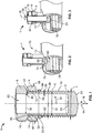
- the fastener bolt 1 comprises two different parts, namely a bolt part 2 and a nut part 4.
- the nut part 4 can be screwed onto a thread section 6 of the bolt part, until the nut part 4 rests against a head section 8 of the bolt part 2.
- the thread section 6 is provided with an external thread 10, the nut part 4 with an internal thread 12 which matches the external thread 10.
- the nut part 4 is provided with an external drive section 14, such as an external hex or square.
- the head section 8 is preferably also provided with an external drive section 16 which preferably is identical to the external drive section 14 of the nut part 4.
- the drive sections 14, 16 are preferably aligned. This is achieved by a matching start of the thread 10 which considers the dimensions of the nut part 4.
- the bolt part 2 is provided with a blind hole 20.
- the blind hole 20 may extend through the head section 8 into the thread section 6 coaxially to the axial direction 18.
- a bottom 22 of the blind hole 20 is located between one and five thread pitches in the axial direction spaced apart from a bottom 24 of the thread section 6 opposite the head section 8.
- the bottom 24 of the thread section 6 may be convex, i.e. having a dome shape and may, generally, have any appropriate shape depending on the particular application.
- the blind hole 20 may extend through the bottom 24 of the thread section 6, so that its bottom is located in or close to the head section 8.
- the bolt 1 may be completely hollow, i.e. sleeve-like. In this case a through hole 20 (not shown) is provided.
- the blind hole 20 leaves a wall thickness 26 in the thread section 6 which is configured to withstand a predetermined tensile breaking stress.
- the thread section 6 has a tensile break strength which is determined by the wall thickness 26.
- the predetermined tensile break strength is obtained within given tolerances.
- the wall thickness 26 is measured in a radial direction 34 and determined by the diameter 36 of the blind hole 20.
- the bolt part 2 is further provided with a shearing section 40, which may be a groove 42 which is continuous in a circumferential direction 44 around the axial direction 18.
- a wall thickness 46 of the bolt part 2 underneath a bottom of the groove 42 in the radial direction 34 is smaller than the wall thickness 26 in the thread section 6.
- the shearing section 40 breaking resistance of the bolt part 2 against shear stress is reduced as compared to its immediate surroundings.
- the shearing section 40 is preferably arranged between the thread section 6 and the head section 8.
- a bottom surface 48 of the head section 8 facing towards the thread section 6 in the axial direction 18 may continue preferably seamlessly as a wall of the groove 42.
- the shoulder 50 does not have a thread and preferably has a diameter which is larger than the minor diameter 30 of the thread 10.
- the shearing section 40 is designed to have a predetermined shear breaking strength. If the shear breaking strength is exceeded, the bolt part 2 will break at the shearing section. This will happen if a fastening torque which is applied to the drive section 16 of the head section 8 exceeds a predetermined value.
- the nut part 4 may comprise a protrusion 52 which protrudes from a bottom surface in the axial direction.
- An outer diameter 56 of the protrusion 52 is preferably smaller than an outer diameter 58 of the drive section 14.
- the protrusion 52 may be a ring-shaped collar 60.
- the internal thread 12 of the nut part 4 may continue on the protrusion 52.
- a bottom 62 facing in the axial direction 18 away from the head section 8 is preferably planar and perpendicular to the axial direction 18.
- an electric connector 70 which comprises the fastener bolt 1 as described above.
- the fastener bolt 1 is screwed into a threaded hole 72 in a wall 74 of the connector 70.
- the connector 70 further comprises a receptacle 76 for receiving at least one or, as shown, a plurality of wire strands 78 of a stranded electric wire 80 from which electric insulation has been removed.
- the receptacle 76 may be a circular opening which is surrounded by the wall 74.
- the receptacle 76 may have a polygonal and/or generally rounded cross-section.
- a separate wall (not shown) may be situated opposite the wall 74.
- the fastener bolt 1 is used to be tightened against the at least one wire strand 78 so that both a tight mechanical and tight electric connection between the wire strand 78 and the connector 70 is generated. How this is done is further explained with reference to Fig. 3 .
- the threads 10, 12 as well as an internal thread 82 of the threaded hole 72 are not shown for simplicity.
- a fastening torque 84 is generated around the axial direction by e.g. a tool which engages the drive section 16 of the head section 8, preferably both the drive section 16 and the drive section 14 of the nut part 4.
- the fastening torque 84 drives the fastening bolt 1 into the receptacle 76 against the at least one wire strand 78. Once the bottom 24 of the fastener bolt 1 rests against the at least one wire strand 78, pressure exerted on the at least one wire strand 78 is increased by increasing the fastening torque 84. If more than one wire strand 78 is provided, increasing the pressure compresses the single wire strand and eliminates gaps between the individual strands, thus decreasing any transitional electric resistances and effecting tighter mechanical connection.
- the fastening torque 84 works against the resistance both in the threaded hole 72 as well as the resistance of the at least one wire strand 78 against elastic and plastic deformation.
- the predetermined fastening torque and the predetermined shear breaking strength at the shearing section 40 will be exceeded. If this happens, the head section 8 separates from the thread section 6 along the shearing section 40.
- the nut part 4 remains on the thread section 6. This is shown in Fig. 4 .
- the nut part 4 is tightened against the wall 74.
- the protrusion 52 thereby comes to rest against a resting area 86 which surrounds the threaded hole 72 on the side of the wall 74 facing away from the receptacle 76 and/or facing the fastener bolt 1.
- the resting area 86 may at least be one of planar and annular. In particular the resting area 86 is shaped complementary to the bottom 62 of the protrusion.
- the threaded hole 72 and/or the resting area 86 may be surrounded by a depression 88 which can be trough-like and have a concave cross-section in a cut parallel to the axial direction 18.
- tensile stresses are generated in the small gap 90 between the internal thread 82 of the threaded hole 72 and the internal thread 12 of the nut part 4.
- the tensile stresses are symbolically shown as arrows 92 in Fig. 5 . If the tensile stress 92 in the gap 90 exceeds the predetermined tensile breaking strength of the thread section 6, the thread section 6 will break. The break occurs in the gap 90, i.e. just above the threaded hole 70, in a root of the thread 10., A part of the thread section 6 remains in the threaded hole 72 and still presses against the at least one wire strand 78. This is shown in Fig. 6 .
- a cap (not shown) made from rubber or resin may be inserted into the blind hole to seal it.
- the break 94 follows the pitch of the thread 10, and as the gap 90 preferably has a maximum length in the axial direction 18 of less than one pitch of the thread 10, the break 94 will not protrude in the axial direction 18 for more than two thread pitches. This height may be covered by the depression 88 so that heat shrink tubes will not be damaged by any potentially sharp edges of the break 94. Further, injuries due to any sharp edges may also be prevented.
- Fig. 8 shows a detail of one embodiment of the threaded hole 72 where, again, the internal thread 82 is not shown for simplicity.
- the annular resting area 86 which is shaped complementary to the bottom 62 of the protrusion 52 can be seen clearly.
- the resting area 86 is preferably surrounded by a ring-like shoulder 96 which protrudes away from the threaded hole 72 in the axial direction 18.
- a height 98 of the shoulder 96 in the axial direction 18 is at least one thread pitch, preferably less than two thread pitches, most preferably around 1.5 thread pitches. This ensures that the break 94 is shielded radially by the shoulder 96 which forms a protective wall around the break 94.
- the trough-like depression 88 may surround the resting area 86 and the shoulder 96.
- the depression 88 can be shallow so that the connector 70 may remain compact. Further, by having only a small contact surface between the nut part 4 and the wall 74, frictional forces are low and thus, the fastening torque 84 is efficiently translated into tensile stress 92. This allows breaking the thread section 6 without the need of excessive manual force.
- one of the bottom surface of the nut and the resting area may be provided with one or more axial protrusions which extend over only a part of the circumference of the threaded hole 72 or the nut part 4 to further reduce the contact area.
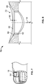
- the break 94 will follow the pitch of the thread 10.
- the break 94 will be generated in a root 100, i.e. valley of the thread 10. It will then follow the root for about one complete turn and then cross the crest 102 of the thread 10 to join with the starting point of the break in the root which is axially adjacent to the break.
- the crossing of the crest 102 has a high likelihood of generating a sharp edge and thus should take place at a shallow angle.
- the breakage line 104 is preferably slanted both with respect to the pitch of the thread 10 and with respect to the axial direction 18.
- the breakage line 104 is a line-like weakening of the tensile break strength of the thread section 6.
- the breakage line is preferably limited to the crest 102.
- the breakage line 104 may be a groove which extends across the crest 102 from one neighboring root 100 to the axially adjacent root 100.
- the breakage line 104 may in particular be a groove or a series of aligned grooves.
- the depth of the grooves may correspond to the depth of the root 100 of the thread 10, so that the wall thickness 26 of the thread section 6 is the same in the breakage line 104 as in the roots 100.
- the breakage line 104 may also be shallower than a root 100 or deeper.
- the at least one breakage line 104 may be helical.
- the handedness of the helix of the breakage line 104 may be opposite to the handedness of the thread 10.
- An angle 106 between the breakage line 104 and a crest 102 may in particular be less than 50°. The angle 106 is measured at the crossing of the breakage line 104 and a crest 102 in the quadrant facing in the turning sense of the screw-in direction and situation towards the head section 8 of the fastener bolt 1.
- breakage line 104 For every 360° turn of a crest 102, there are at least two crossings of a breakage line 104.
- two or more helical breakage lines may be provided.
- the pitch of the breakage line 104 is higher by an integer factor than the pitch of the thread 10.
- the fastener bolt 1 of Fig. 10 differs from the one shown in Fig. 9 in that the at least one breakage line 104 is located on an inner wall 108 of the thread section 6.
- the inner wall may be formed by the through or blind hole 20.
- the layout of the at least one breakage line 104 may be the same as the layout of the breakage line 104 of Fig. 9 , i.e. the breakage line 104 may wind helically around the inner wall 108 and have a handedness which is opposite to the handedness of the external thread 10.
- the pitch of the breakage line 104 may be larger than the pitch of the external thread 6.
- the pitch of the breakage line 104 in any embodiment may be between two and five times the pitch of the external thread 6, for example, as shown in Fig. 10 , three times the pitch of the external thread 6.
- the breakage line 104 is located on the inner wall 108, it is preferably configured as a continuous groove having a V-shaped cross-section.
Priority Applications (6)
| Application Number | Priority Date | Filing Date | Title |
|---|---|---|---|
| EP17305443.8A EP3388697B1 (de) | 2017-04-13 | 2017-04-13 | Abreissbarer befestigungsbolzen und verfahren zum einspannen elektrischer drähte sowie elektrischer verbinder mit einem abreissbaren bolzen ohne vorsprung |
| JP2020505530A JP6858306B2 (ja) | 2017-04-13 | 2018-04-12 | 剪断可能なファスナボルトおよび電線を圧着する方法、ならびに突出のない剪断可能なファスナを備える電気コネクタ |
| CN201880024553.7A CN110537031B (zh) | 2017-04-13 | 2018-04-12 | 可剪切的紧固件螺栓和夹紧电线的方法,以及包括零凸出部可剪切的紧固件的电连接器 |
| PCT/EP2018/059467 WO2018189339A1 (en) | 2017-04-13 | 2018-04-12 | Shearable fastener bolt and method for clamping electric wires, and electric connector comprising a zero-protrusion shearable fastener |
| US16/599,743 US11092185B2 (en) | 2017-04-13 | 2019-10-11 | Shearable fastener bolt and method for clamping electric wires, and electrical connector comprising a zero-protrusion shearable fastener |
| US17/380,572 US20210348637A1 (en) | 2017-04-13 | 2021-07-20 | Shearable Fastener Bolt And Method For Clamping Electric Wires, And Electrical Connector Comprising A Zero-Protrusion Shearable Fastener |
Applications Claiming Priority (1)
| Application Number | Priority Date | Filing Date | Title |
|---|---|---|---|
| EP17305443.8A EP3388697B1 (de) | 2017-04-13 | 2017-04-13 | Abreissbarer befestigungsbolzen und verfahren zum einspannen elektrischer drähte sowie elektrischer verbinder mit einem abreissbaren bolzen ohne vorsprung |
Publications (2)
| Publication Number | Publication Date |
|---|---|
| EP3388697A1 true EP3388697A1 (de) | 2018-10-17 |
| EP3388697B1 EP3388697B1 (de) | 2021-12-01 |
Family
ID=58606222
Family Applications (1)
| Application Number | Title | Priority Date | Filing Date |
|---|---|---|---|
| EP17305443.8A Active EP3388697B1 (de) | 2017-04-13 | 2017-04-13 | Abreissbarer befestigungsbolzen und verfahren zum einspannen elektrischer drähte sowie elektrischer verbinder mit einem abreissbaren bolzen ohne vorsprung |
Country Status (5)
| Country | Link |
|---|---|
| US (2) | US11092185B2 (de) |
| EP (1) | EP3388697B1 (de) |
| JP (1) | JP6858306B2 (de) |
| CN (1) | CN110537031B (de) |
| WO (1) | WO2018189339A1 (de) |
Families Citing this family (3)
| Publication number | Priority date | Publication date | Assignee | Title |
|---|---|---|---|---|
| FI127656B (en) * | 2017-11-29 | 2018-11-30 | Ensto Oy | CUTTING SCREW |
| EP3771838B1 (de) * | 2019-07-30 | 2022-03-02 | Tyco Electronics-Simel | Abreissschraube mit drehmomentbegrenzungsabschnitt |
| FR3108861B1 (fr) * | 2020-04-07 | 2022-06-24 | Aptar France Sas | Distributeur de produit fluide |
Citations (8)
| Publication number | Priority date | Publication date | Assignee | Title |
|---|---|---|---|---|
| GB2299640A (en) * | 1995-04-07 | 1996-10-09 | B & H Ltd | Shearable fastener |
| EP1460278A1 (de) * | 2003-03-17 | 2004-09-22 | Pfisterer Kontaktsysteme GmbH & Co. KG | Befestigungsmittel, insbesondere Abreissschraube, und zugehörige Schraubverbindungsklemme |
| EP1911981A2 (de) | 2006-10-10 | 2008-04-16 | Pfisterer Kontaktsysteme GmbH & Co. KG | Befestigungsmittel, insbesondere Abreißschraube, mit abtrennbarem Klemmabschnitt |
| EP2322816A1 (de) * | 2009-11-17 | 2011-05-18 | Nexans | Klemmschraube |
| US20120202393A1 (en) * | 2011-02-08 | 2012-08-09 | Gert Stauch | Arrangement with a clamp of metal constructed as a pipe piece |
| EP2498339A1 (de) * | 2011-03-11 | 2012-09-12 | Nexans | Klemmschraube |
| EP2657548A2 (de) * | 2012-04-26 | 2013-10-30 | Arcus Elektrotechnik Alois Schiffmann GmbH | Abreißschraube |
| EP2846052A1 (de) * | 2013-09-06 | 2015-03-11 | Thomas & Betts International, LLC | Drehmomentsteuerungs-Brechschraube |
Family Cites Families (16)
| Publication number | Priority date | Publication date | Assignee | Title |
|---|---|---|---|---|
| US3444775A (en) * | 1968-02-16 | 1969-05-20 | Lockheed Aircraft Corp | Nut formed with multiple torque-off collars |
| GB9404979D0 (en) * | 1994-03-15 | 1994-04-27 | Sicame Electrical Dev Ltd | Improvements relating to clamping screws |
| DE59800512D1 (de) * | 1998-08-18 | 2001-04-12 | Gerhard Petri Gmbh & Co Kg | Abreisskopfschraube |
| US6071145A (en) * | 1999-02-01 | 2000-06-06 | Toly; Elde V. | Contact housing for electrical connector |
| GB0202710D0 (en) | 2002-02-06 | 2002-03-20 | Tyco Electronics Ltd Uk | Fastener |
| DK2071201T3 (da) * | 2007-12-11 | 2010-07-05 | Nexans | Afklipningsskrue |
| US7658657B1 (en) * | 2009-02-26 | 2010-02-09 | Hubbell Incorporated | Single-pole electrical connector having a steel retaining spring |
| AU2012200645A1 (en) * | 2011-02-08 | 2012-08-23 | Nexans | Arrangement with a Clamp of Metal Constructed as a Pipe Piece |
| PL2498338T3 (pl) | 2011-03-11 | 2014-05-30 | Nexans | Zestaw z zaciskiem z metalu zrealizowanym w postaci kształtki rurowej i z co najmniej jedną śrubą zaciskową |
| CN102760978B (zh) * | 2011-04-27 | 2015-04-01 | 泰科电子(上海)有限公司 | 电连接装置 |
| US9203191B2 (en) * | 2012-02-17 | 2015-12-01 | Integro Llc | Portable power connector |
| US8747170B2 (en) * | 2012-05-02 | 2014-06-10 | Tyco Electronics Corporation | Connector assemblies and systems and methods for forming disconnectable joint assemblies |
| DE102012013176A1 (de) * | 2012-06-29 | 2014-01-02 | Pfisterer Kontaktsysteme Gmbh | Abreißschraube, zugehöriges System sowie Vorrichtung zum Schraubklemmen elektrischer Leiter mit einer solchen Abreißschraube |
| EP2999053B1 (de) * | 2014-09-22 | 2017-11-08 | Tyco Electronics Simel S.A.S. | Drahtverbindungsanordnung mit teleskopischer Klemmschraube |
| US11193522B2 (en) * | 2016-11-30 | 2021-12-07 | 3M Innovative Properties Company | Shear bolt |
| FI127656B (en) * | 2017-11-29 | 2018-11-30 | Ensto Oy | CUTTING SCREW |
-
2017
- 2017-04-13 EP EP17305443.8A patent/EP3388697B1/de active Active
-
2018
- 2018-04-12 WO PCT/EP2018/059467 patent/WO2018189339A1/en active Application Filing
- 2018-04-12 JP JP2020505530A patent/JP6858306B2/ja active Active
- 2018-04-12 CN CN201880024553.7A patent/CN110537031B/zh active Active
-
2019
- 2019-10-11 US US16/599,743 patent/US11092185B2/en active Active
-
2021
- 2021-07-20 US US17/380,572 patent/US20210348637A1/en active Pending
Patent Citations (8)
| Publication number | Priority date | Publication date | Assignee | Title |
|---|---|---|---|---|
| GB2299640A (en) * | 1995-04-07 | 1996-10-09 | B & H Ltd | Shearable fastener |
| EP1460278A1 (de) * | 2003-03-17 | 2004-09-22 | Pfisterer Kontaktsysteme GmbH & Co. KG | Befestigungsmittel, insbesondere Abreissschraube, und zugehörige Schraubverbindungsklemme |
| EP1911981A2 (de) | 2006-10-10 | 2008-04-16 | Pfisterer Kontaktsysteme GmbH & Co. KG | Befestigungsmittel, insbesondere Abreißschraube, mit abtrennbarem Klemmabschnitt |
| EP2322816A1 (de) * | 2009-11-17 | 2011-05-18 | Nexans | Klemmschraube |
| US20120202393A1 (en) * | 2011-02-08 | 2012-08-09 | Gert Stauch | Arrangement with a clamp of metal constructed as a pipe piece |
| EP2498339A1 (de) * | 2011-03-11 | 2012-09-12 | Nexans | Klemmschraube |
| EP2657548A2 (de) * | 2012-04-26 | 2013-10-30 | Arcus Elektrotechnik Alois Schiffmann GmbH | Abreißschraube |
| EP2846052A1 (de) * | 2013-09-06 | 2015-03-11 | Thomas & Betts International, LLC | Drehmomentsteuerungs-Brechschraube |
Also Published As
| Publication number | Publication date |
|---|---|
| JP2020516831A (ja) | 2020-06-11 |
| CN110537031B (zh) | 2022-01-11 |
| EP3388697B1 (de) | 2021-12-01 |
| JP6858306B2 (ja) | 2021-04-14 |
| US11092185B2 (en) | 2021-08-17 |
| US20200040930A1 (en) | 2020-02-06 |
| CN110537031A (zh) | 2019-12-03 |
| US20210348637A1 (en) | 2021-11-11 |
| WO2018189339A1 (en) | 2018-10-18 |
Similar Documents
| Publication | Publication Date | Title |
|---|---|---|
| US20210348637A1 (en) | Shearable Fastener Bolt And Method For Clamping Electric Wires, And Electrical Connector Comprising A Zero-Protrusion Shearable Fastener | |
| EP2679835B1 (de) | Befestigungselement mit Gewinde | |
| RU2042056C1 (ru) | Винт для изготовления гладких или резьбовых отверстий | |
| EP3354912B1 (de) | Schraube | |
| US20160327081A1 (en) | Screw, fastening arrangement and use of a screw | |
| EP2999053B1 (de) | Drahtverbindungsanordnung mit teleskopischer Klemmschraube | |
| US4827756A (en) | Fastener fabrication method | |
| US20220145923A1 (en) | Break-Off Bolt with Torque-Limiting Section | |
| EP2999054B1 (de) | Klemmschraube für eine Drahtverbindungsanordnung und Drahtverbindungsanordnung | |
| FI127657B (en) | CUTTING SCREW | |
| CA2771001C (en) | Threaded sleeves | |
| EP3388696B1 (de) | Abreissschraube für eine drahtverbindungsanordnung und drahtverbindungsanordnung | |
| EP3792509B1 (de) | Drehmomentbegrenzungsmutter für einen abreissbolzen | |
| JP2010255775A (ja) | 管継手、管接続構造及び管接続方法 | |
| EP3454421B1 (de) | Scherschraube und anwendung davon | |
| EP2395252A1 (de) | Verbindungsanordnung und Verfahren zur Befestigung einer Schraube | |
| JP2020035601A (ja) | 電線接続用コネクタ、及び、せん断ボルト | |
| RU2054584C1 (ru) | Заклепка |
Legal Events
| Date | Code | Title | Description |
|---|---|---|---|
| PUAI | Public reference made under article 153(3) epc to a published international application that has entered the european phase |
Free format text: ORIGINAL CODE: 0009012 |
|
| STAA | Information on the status of an ep patent application or granted ep patent |
Free format text: STATUS: THE APPLICATION HAS BEEN PUBLISHED |
|
| AK | Designated contracting states |
Kind code of ref document: A1 Designated state(s): AL AT BE BG CH CY CZ DE DK EE ES FI FR GB GR HR HU IE IS IT LI LT LU LV MC MK MT NL NO PL PT RO RS SE SI SK SM TR |
|
| AX | Request for extension of the european patent |
Extension state: BA ME |
|
| STAA | Information on the status of an ep patent application or granted ep patent |
Free format text: STATUS: REQUEST FOR EXAMINATION WAS MADE |
|
| 17P | Request for examination filed |
Effective date: 20190417 |
|
| RBV | Designated contracting states (corrected) |
Designated state(s): AL AT BE BG CH CY CZ DE DK EE ES FI FR GB GR HR HU IE IS IT LI LT LU LV MC MK MT NL NO PL PT RO RS SE SI SK SM TR |
|
| GRAP | Despatch of communication of intention to grant a patent |
Free format text: ORIGINAL CODE: EPIDOSNIGR1 |
|
| STAA | Information on the status of an ep patent application or granted ep patent |
Free format text: STATUS: GRANT OF PATENT IS INTENDED |
|
| INTG | Intention to grant announced |
Effective date: 20210622 |
|
| GRAS | Grant fee paid |
Free format text: ORIGINAL CODE: EPIDOSNIGR3 |
|
| GRAA | (expected) grant |
Free format text: ORIGINAL CODE: 0009210 |
|
| STAA | Information on the status of an ep patent application or granted ep patent |
Free format text: STATUS: THE PATENT HAS BEEN GRANTED |
|
| AK | Designated contracting states |
Kind code of ref document: B1 Designated state(s): AL AT BE BG CH CY CZ DE DK EE ES FI FR GB GR HR HU IE IS IT LI LT LU LV MC MK MT NL NO PL PT RO RS SE SI SK SM TR |
|
| REG | Reference to a national code |
Ref country code: GB Ref legal event code: FG4D |
|
| REG | Reference to a national code |
Ref country code: AT Ref legal event code: REF Ref document number: 1452029 Country of ref document: AT Kind code of ref document: T Effective date: 20211215 Ref country code: CH Ref legal event code: EP |
|
| REG | Reference to a national code |
Ref country code: IE Ref legal event code: FG4D |
|
| REG | Reference to a national code |
Ref country code: DE Ref legal event code: R096 Ref document number: 602017050120 Country of ref document: DE |
|
| REG | Reference to a national code |
Ref country code: NO Ref legal event code: T2 Effective date: 20211201 |
|
| REG | Reference to a national code |
Ref country code: FI Ref legal event code: FGE |
|
| REG | Reference to a national code |
Ref country code: NL Ref legal event code: FP |
|
| REG | Reference to a national code |
Ref country code: SE Ref legal event code: TRGR |
|
| REG | Reference to a national code |
Ref country code: LT Ref legal event code: MG9D |
|
| REG | Reference to a national code |
Ref country code: AT Ref legal event code: MK05 Ref document number: 1452029 Country of ref document: AT Kind code of ref document: T Effective date: 20211201 |
|
| PG25 | Lapsed in a contracting state [announced via postgrant information from national office to epo] |
Ref country code: RS Free format text: LAPSE BECAUSE OF FAILURE TO SUBMIT A TRANSLATION OF THE DESCRIPTION OR TO PAY THE FEE WITHIN THE PRESCRIBED TIME-LIMIT Effective date: 20211201 Ref country code: LT Free format text: LAPSE BECAUSE OF FAILURE TO SUBMIT A TRANSLATION OF THE DESCRIPTION OR TO PAY THE FEE WITHIN THE PRESCRIBED TIME-LIMIT Effective date: 20211201 Ref country code: BG Free format text: LAPSE BECAUSE OF FAILURE TO SUBMIT A TRANSLATION OF THE DESCRIPTION OR TO PAY THE FEE WITHIN THE PRESCRIBED TIME-LIMIT Effective date: 20220301 Ref country code: AT Free format text: LAPSE BECAUSE OF FAILURE TO SUBMIT A TRANSLATION OF THE DESCRIPTION OR TO PAY THE FEE WITHIN THE PRESCRIBED TIME-LIMIT Effective date: 20211201 |
|
| PG25 | Lapsed in a contracting state [announced via postgrant information from national office to epo] |
Ref country code: PL Free format text: LAPSE BECAUSE OF FAILURE TO SUBMIT A TRANSLATION OF THE DESCRIPTION OR TO PAY THE FEE WITHIN THE PRESCRIBED TIME-LIMIT Effective date: 20211201 Ref country code: LV Free format text: LAPSE BECAUSE OF FAILURE TO SUBMIT A TRANSLATION OF THE DESCRIPTION OR TO PAY THE FEE WITHIN THE PRESCRIBED TIME-LIMIT Effective date: 20211201 Ref country code: HR Free format text: LAPSE BECAUSE OF FAILURE TO SUBMIT A TRANSLATION OF THE DESCRIPTION OR TO PAY THE FEE WITHIN THE PRESCRIBED TIME-LIMIT Effective date: 20211201 Ref country code: GR Free format text: LAPSE BECAUSE OF FAILURE TO SUBMIT A TRANSLATION OF THE DESCRIPTION OR TO PAY THE FEE WITHIN THE PRESCRIBED TIME-LIMIT Effective date: 20220302 Ref country code: ES Free format text: LAPSE BECAUSE OF FAILURE TO SUBMIT A TRANSLATION OF THE DESCRIPTION OR TO PAY THE FEE WITHIN THE PRESCRIBED TIME-LIMIT Effective date: 20211201 |
|
| PG25 | Lapsed in a contracting state [announced via postgrant information from national office to epo] |
Ref country code: SM Free format text: LAPSE BECAUSE OF FAILURE TO SUBMIT A TRANSLATION OF THE DESCRIPTION OR TO PAY THE FEE WITHIN THE PRESCRIBED TIME-LIMIT Effective date: 20211201 Ref country code: SK Free format text: LAPSE BECAUSE OF FAILURE TO SUBMIT A TRANSLATION OF THE DESCRIPTION OR TO PAY THE FEE WITHIN THE PRESCRIBED TIME-LIMIT Effective date: 20211201 Ref country code: RO Free format text: LAPSE BECAUSE OF FAILURE TO SUBMIT A TRANSLATION OF THE DESCRIPTION OR TO PAY THE FEE WITHIN THE PRESCRIBED TIME-LIMIT Effective date: 20211201 Ref country code: PT Free format text: LAPSE BECAUSE OF FAILURE TO SUBMIT A TRANSLATION OF THE DESCRIPTION OR TO PAY THE FEE WITHIN THE PRESCRIBED TIME-LIMIT Effective date: 20220401 Ref country code: EE Free format text: LAPSE BECAUSE OF FAILURE TO SUBMIT A TRANSLATION OF THE DESCRIPTION OR TO PAY THE FEE WITHIN THE PRESCRIBED TIME-LIMIT Effective date: 20211201 Ref country code: CZ Free format text: LAPSE BECAUSE OF FAILURE TO SUBMIT A TRANSLATION OF THE DESCRIPTION OR TO PAY THE FEE WITHIN THE PRESCRIBED TIME-LIMIT Effective date: 20211201 |
|
| REG | Reference to a national code |
Ref country code: DE Ref legal event code: R026 Ref document number: 602017050120 Country of ref document: DE |
|
| PLBI | Opposition filed |
Free format text: ORIGINAL CODE: 0009260 |
|
| PLAB | Opposition data, opponent's data or that of the opponent's representative modified |
Free format text: ORIGINAL CODE: 0009299OPPO |
|
| PLAF | Information modified related to communication of a notice of opposition and request to file observations + time limit |
Free format text: ORIGINAL CODE: EPIDOSCOBS2 |
|
| PLAX | Notice of opposition and request to file observation + time limit sent |
Free format text: ORIGINAL CODE: EPIDOSNOBS2 |
|
| REG | Reference to a national code |
Ref country code: FI Ref legal event code: MDE Opponent name: ERHARDT, MARTIN |
|
| 26 | Opposition filed |
Opponent name: ERHARDT, MARTIN Effective date: 20220825 |
|
| PG25 | Lapsed in a contracting state [announced via postgrant information from national office to epo] |
Ref country code: IS Free format text: LAPSE BECAUSE OF FAILURE TO SUBMIT A TRANSLATION OF THE DESCRIPTION OR TO PAY THE FEE WITHIN THE PRESCRIBED TIME-LIMIT Effective date: 20220401 |
|
| R26 | Opposition filed (corrected) |
Opponent name: ERHARDT, MARTIN Effective date: 20220825 |
|
| PG25 | Lapsed in a contracting state [announced via postgrant information from national office to epo] |
Ref country code: DK Free format text: LAPSE BECAUSE OF FAILURE TO SUBMIT A TRANSLATION OF THE DESCRIPTION OR TO PAY THE FEE WITHIN THE PRESCRIBED TIME-LIMIT Effective date: 20211201 Ref country code: AL Free format text: LAPSE BECAUSE OF FAILURE TO SUBMIT A TRANSLATION OF THE DESCRIPTION OR TO PAY THE FEE WITHIN THE PRESCRIBED TIME-LIMIT Effective date: 20211201 |
|
| PG25 | Lapsed in a contracting state [announced via postgrant information from national office to epo] |
Ref country code: SI Free format text: LAPSE BECAUSE OF FAILURE TO SUBMIT A TRANSLATION OF THE DESCRIPTION OR TO PAY THE FEE WITHIN THE PRESCRIBED TIME-LIMIT Effective date: 20211201 |
|
| REG | Reference to a national code |
Ref country code: CH Ref legal event code: PL |
|
| REG | Reference to a national code |
Ref country code: BE Ref legal event code: MM Effective date: 20220430 |
|
| PLBB | Reply of patent proprietor to notice(s) of opposition received |
Free format text: ORIGINAL CODE: EPIDOSNOBS3 |
|
| PG25 | Lapsed in a contracting state [announced via postgrant information from national office to epo] |
Ref country code: MC Free format text: LAPSE BECAUSE OF FAILURE TO SUBMIT A TRANSLATION OF THE DESCRIPTION OR TO PAY THE FEE WITHIN THE PRESCRIBED TIME-LIMIT Effective date: 20211201 Ref country code: LU Free format text: LAPSE BECAUSE OF NON-PAYMENT OF DUE FEES Effective date: 20220413 Ref country code: LI Free format text: LAPSE BECAUSE OF NON-PAYMENT OF DUE FEES Effective date: 20220430 Ref country code: CH Free format text: LAPSE BECAUSE OF NON-PAYMENT OF DUE FEES Effective date: 20220430 |
|
| PG25 | Lapsed in a contracting state [announced via postgrant information from national office to epo] |
Ref country code: BE Free format text: LAPSE BECAUSE OF NON-PAYMENT OF DUE FEES Effective date: 20220430 |
|
| PG25 | Lapsed in a contracting state [announced via postgrant information from national office to epo] |
Ref country code: IE Free format text: LAPSE BECAUSE OF NON-PAYMENT OF DUE FEES Effective date: 20220413 |
|
| PGFP | Annual fee paid to national office [announced via postgrant information from national office to epo] |
Ref country code: FR Payment date: 20230309 Year of fee payment: 7 |
|
| PG25 | Lapsed in a contracting state [announced via postgrant information from national office to epo] |
Ref country code: IT Free format text: LAPSE BECAUSE OF FAILURE TO SUBMIT A TRANSLATION OF THE DESCRIPTION OR TO PAY THE FEE WITHIN THE PRESCRIBED TIME-LIMIT Effective date: 20211201 |
|
| PGFP | Annual fee paid to national office [announced via postgrant information from national office to epo] |
Ref country code: SE Payment date: 20230310 Year of fee payment: 7 Ref country code: GB Payment date: 20230302 Year of fee payment: 7 |
|
| PGFP | Annual fee paid to national office [announced via postgrant information from national office to epo] |
Ref country code: NO Payment date: 20230412 Year of fee payment: 7 Ref country code: DE Payment date: 20230307 Year of fee payment: 7 |
|
| PGFP | Annual fee paid to national office [announced via postgrant information from national office to epo] |
Ref country code: FI Payment date: 20230411 Year of fee payment: 7 |
|
| PG25 | Lapsed in a contracting state [announced via postgrant information from national office to epo] |
Ref country code: HU Free format text: LAPSE BECAUSE OF FAILURE TO SUBMIT A TRANSLATION OF THE DESCRIPTION OR TO PAY THE FEE WITHIN THE PRESCRIBED TIME-LIMIT; INVALID AB INITIO Effective date: 20170413 |
|
| PGFP | Annual fee paid to national office [announced via postgrant information from national office to epo] |
Ref country code: NL Payment date: 20240315 Year of fee payment: 8 |
|
| PG25 | Lapsed in a contracting state [announced via postgrant information from national office to epo] |
Ref country code: MK Free format text: LAPSE BECAUSE OF FAILURE TO SUBMIT A TRANSLATION OF THE DESCRIPTION OR TO PAY THE FEE WITHIN THE PRESCRIBED TIME-LIMIT Effective date: 20211201 Ref country code: CY Free format text: LAPSE BECAUSE OF FAILURE TO SUBMIT A TRANSLATION OF THE DESCRIPTION OR TO PAY THE FEE WITHIN THE PRESCRIBED TIME-LIMIT Effective date: 20211201 |
|
| PGFP | Annual fee paid to national office [announced via postgrant information from national office to epo] |
Ref country code: GB Payment date: 20240229 Year of fee payment: 8 |