EP3388200B1 - Dispositif de remise en état de chaînes - Google Patents
Dispositif de remise en état de chaînes Download PDFInfo
- Publication number
- EP3388200B1 EP3388200B1 EP18166933.4A EP18166933A EP3388200B1 EP 3388200 B1 EP3388200 B1 EP 3388200B1 EP 18166933 A EP18166933 A EP 18166933A EP 3388200 B1 EP3388200 B1 EP 3388200B1
- Authority
- EP
- European Patent Office
- Prior art keywords
- track
- chain
- crawler belt
- crawler
- servicing apparatus
- Prior art date
- Legal status (The legal status is an assumption and is not a legal conclusion. Google has not performed a legal analysis and makes no representation as to the accuracy of the status listed.)
- Active
Links
- 238000003825 pressing Methods 0.000 claims description 16
- 230000007246 mechanism Effects 0.000 claims description 6
- 238000012545 processing Methods 0.000 claims description 5
- 230000005484 gravity Effects 0.000 claims description 4
- 238000007790 scraping Methods 0.000 claims 14
- 230000003247 decreasing effect Effects 0.000 claims 1
- 238000006073 displacement reaction Methods 0.000 claims 1
- 230000002441 reversible effect Effects 0.000 claims 1
- 230000008439 repair process Effects 0.000 description 54
- 238000000034 method Methods 0.000 description 23
- 230000008569 process Effects 0.000 description 23
- 238000000605 extraction Methods 0.000 description 13
- 230000032258 transport Effects 0.000 description 8
- 230000006978 adaptation Effects 0.000 description 4
- 238000004804 winding Methods 0.000 description 3
- 230000008859 change Effects 0.000 description 2
- 210000000078 claw Anatomy 0.000 description 2
- 238000010276 construction Methods 0.000 description 2
- 230000000694 effects Effects 0.000 description 2
- 239000011295 pitch Substances 0.000 description 2
- 125000006850 spacer group Chemical group 0.000 description 2
- 230000001419 dependent effect Effects 0.000 description 1
- 238000011161 development Methods 0.000 description 1
- 230000018109 developmental process Effects 0.000 description 1
- 230000003370 grooming effect Effects 0.000 description 1
- 238000003780 insertion Methods 0.000 description 1
- 230000037431 insertion Effects 0.000 description 1
- 230000003993 interaction Effects 0.000 description 1
- JEIPFZHSYJVQDO-UHFFFAOYSA-N iron(III) oxide Inorganic materials O=[Fe]O[Fe]=O JEIPFZHSYJVQDO-UHFFFAOYSA-N 0.000 description 1
- 238000012423 maintenance Methods 0.000 description 1
- 239000002184 metal Substances 0.000 description 1
- 238000005065 mining Methods 0.000 description 1
- 238000012986 modification Methods 0.000 description 1
- 230000004048 modification Effects 0.000 description 1
- 230000008092 positive effect Effects 0.000 description 1
- 230000036316 preload Effects 0.000 description 1
- 230000000717 retained effect Effects 0.000 description 1
- 230000007704 transition Effects 0.000 description 1
- 230000001960 triggered effect Effects 0.000 description 1
- 238000003466 welding Methods 0.000 description 1
Images


Classifications
-
- B—PERFORMING OPERATIONS; TRANSPORTING
- B25—HAND TOOLS; PORTABLE POWER-DRIVEN TOOLS; MANIPULATORS
- B25B—TOOLS OR BENCH DEVICES NOT OTHERWISE PROVIDED FOR, FOR FASTENING, CONNECTING, DISENGAGING OR HOLDING
- B25B27/00—Hand tools, specially adapted for fitting together or separating parts or objects whether or not involving some deformation, not otherwise provided for
- B25B27/14—Hand tools, specially adapted for fitting together or separating parts or objects whether or not involving some deformation, not otherwise provided for for assembling objects other than by press fit or detaching same
- B25B27/22—Hand tools, specially adapted for fitting together or separating parts or objects whether or not involving some deformation, not otherwise provided for for assembling objects other than by press fit or detaching same positioning sprocket chains, endless tracks, antiskid chains
-
- B—PERFORMING OPERATIONS; TRANSPORTING
- B62—LAND VEHICLES FOR TRAVELLING OTHERWISE THAN ON RAILS
- B62D—MOTOR VEHICLES; TRAILERS
- B62D55/00—Endless track vehicles
- B62D55/32—Assembly, disassembly, repair or servicing of endless-track systems
Definitions
- the invention relates to a chain repair device for processing crawler tracks.
- Crawler chains are an integral part of the chassis of a tracked vehicle and are used to drive and steer such vehicles. They are built up modularly from many identical chain links, chain links arranged next to one another being connected by inner and outer chain connectors. In the closed state, crawlers form a revolving belt which is driven by rotating drive wheels engaging in the spaces between the individual chain links.
- crawler tracks can also have chain pads on the individual chain links.
- Another characteristic property of crawler tracks is their high traction, which prevents sliding on the mountain, so that crawler tracks are suitable for use on vehicles or machines for work on slopes.
- Other possible uses are bulldozers on construction sites or snow groomers for grooming ski slopes.
- Crawler chains of particularly large dimensions are also used in mining for conveyor bridges.
- crawler tracks are preferred for large and heavy vehicles and machines.
- the suitable crawler tracks also have large dimensions and a high weight. Due to the enormous dimensions of a crawler belt, repairing it is associated with considerable effort.
- the crawler belt is usually dismantled with hand-held tools and broken down into individual links in order to enable the individual components, such as the chain cushions, to be exchanged.
- the disadvantage is that both the dismantling of the crawler belt and the subsequent assembly of the individual crawler belt elements and the subsequent assembly of the crawler belt to the crawler vehicle take a lot of time and require a great deal of effort.
- DE 80 25 249 U1 a device for pulling out chain cushions from crawlers is described.
- the pull-out device which has two connected claws that can be moved relative to one another via a spindle, is positioned on the chain pads of the crawler belt from two sides, one of the claws having a pin for unlocking the chain pad.
- the extractor can be driven, for example, with an impact wrench.
- a problem with the assembly of the crawler belt on the tracked vehicle is caused by the pretensioning of the crawler belt.
- a crawler belt spread out on the floor straightens up a certain distance at the end areas, which makes the chain assembly difficult. Due to the high weight, great forces are also necessary to overcome the given preload.
- a mounting aid for a caterpillar chain is known from the prior art, those in the DE 601 01 513 T2 is described.
- the assembly aid supports the assembly of a ready-to-use crawler belt by pressing the end of the crawler belt down so that the tracked vehicle can retract.
- a chain repair device is also known. With this device, the chain has to be brought into the processing position in a complex manner.
- the object of the invention is to provide a device with which an efficient and economical repair of large and heavy tracks can be realized.
- the object is achieved by a chain repair device according to the invention which is suitable for processing crawler tracks.
- the chain repair device comprises a passive upper roller conveyor and a passive lower roller conveyor arranged below it as well as a first deflection device for deflecting the crawler belt from the lower roller conveyor to the upper roller conveyor and vice versa with an associated drive unit and a second deflection device for deflecting the crawler belt from the upper roller conveyor to the lower roller conveyor and vice versa with an associated drive unit.
- the chain repair device comprises a loading and unloading area for the crawler belt, which extends the lower roller conveyor, with an associated drive unit.
- the upper and the lower roller conveyor together with the deflection devices form a caterpillar conveyor circuit and there is at least one workstation for assembling and disassembling components of the crawler belt within this caterpillar conveyor circuit.
- the task and delivery area expanding the lower roller conveyor is one
- the side is designed to be open, so that the crawler belt can be fed into the crawler belt conveying circuit. This area is also known as the feed area.
- the caterpillar chain can be led out of the caterpillar conveyor circuit via the open side of the loading and unloading area.
- the caterpillar chain is moved within the caterpillar conveyor circuit by the active drive units on the passive roller conveyor so that the various crawler elements can be processed, including the dismantling and reassembly of individual elements of the crawler belt, at the workstations arranged on the roller conveyor, whereby every section of the caterpillar can be led to all workplaces
- a caterpillar conveyor circuit in the sense of the invention is a closed track on which the caterpillar chain can be conveyed in such a way that it passes the same points again and again when it is transported without changing direction, i.e. is again at the same point in the circuit after one revolution.
- This caterpillar conveyor circuit is formed from the upper and the lower roller conveyor and the two deflection devices.
- a roller conveyor is a passive conveying device which, in a friction-reducing manner, for example by means of rotatably mounted rollers, supports or enables the transport of an object, such as a crawler belt, by active drive units.
- the crawler belt After passing through a first deflection device, the crawler belt lies on the upper roller conveyor, rotated by 180 ° compared to the position of the crawler belt on the lower roller conveyor.
- the upper side of the crawler belt becomes the lower side of the crawler belt when the crawler belt changes from the lower to the upper roller conveyor.
- the elements that are placed on the lower roller conveyor at the lower edge of the crawler belt are positioned on the upper roller conveyor at the upper edge of the crawler belt.
- the second deflection device can be switched between two modes, so that either in a zero position the crawler belt can be guided under the second deflection device or in a circulating position, which can also be referred to as circulating mode, along the crawler belt a swivel arm arranged on the deflection device can change from the upper to the lower roller conveyor or vice versa.
- a swivel arm is rotatably mounted about a swivel axis.
- the center of gravity of the swivel arm is preferably balanced in such a way that the swivel arm is designed to be reversibly and automatically foldable due to the weight of the crawler belt to switch between the two modes.
- the swivel arm and thus the deflection device changes between the zero position for retracting and extending the crawler belt and the circulating position for changing the crawler belt between the upper and lower roller conveyor.
- the weight of the crawler belt causes the swivel arm to fold downwards, whereby the swivel arm folds back again without the influence of weight, i.e. after the crawler belt has been pushed back onto the upper roller conveyor.
- the process of folding the swivel arm back into the zero position in the event that the weight of the crawler belt no longer acts on the swivel arm is preferably supported by the spring force of a tension spring attached to the swivel arm.
- several workplaces for processing the crawler belt can be arranged from different sides on the conveying device.
- the different sides are preferably the top and bottom of the track, but such a track can also be machined from both long sides by means of the chain repair device.
- the active drive unit is designed in such a way that it has a pinion drum with drive wheels arranged thereon.
- Two identical drive wheels are preferably arranged at a distance from each other on the pinion drum within the active drive unit.
- the two identical drive wheels are designed so that they can be engaged in the crawler belt, that when the drive wheels engage in the crawler belt, a rotation of the drive wheels causes the crawler belt to move.
- the pair of gears is arranged symmetrically to the center on the pinion so that the two gears have the same distance from the plane of symmetry of the pinion, the plane of symmetry described here being oriented perpendicular to the pinion axis.
- several pairs of drive wheels of different sizes are arranged on the drive unit symmetrically to the center of the pinion drum and spaced apart from one another on the pinion drum, the diameter of the drive wheels increasing from the inside outwards.
- the chain repair device is advantageously universally suitable for different types of track chains, since the drive units can be adapted to different types of track chains.
- a plurality of pairs of drive wheels of different sizes are preferably mounted in a drive unit, so that a change between different crawler tracks is possible without having to re-assemble drive wheels.
- the tooth geometry and the tooth root geometry of the drive wheels are adapted to the outer chain connectors of the respective track chain.
- the root diameter of the smaller, internal drive wheels has at least a size that corresponds to the drum diameter plus twice the chain pin height, in order to enable the meshing of the internal drive wheels and thus ensure the functionality of the internal drive wheels.
- the diameters of the drive wheels are preferably selected so that the tip diameter of the smaller, inner drive wheels is smaller than or equal to the root diameter of the larger, outer drive wheels.
- the distance between the drive wheels is adapted to the widths of the respective crawler tracks so that the teeth of the drive wheels can grip between the outer chain connectors.
- the distance between the outer drive wheels is advantageously at least the width of the narrower crawler belt plus sufficient play of about 30 mm.
- the drive wheels are aligned symmetrically to the center of the pinion drum.
- the absolute width of the roller conveyor below the drive units including the screw head is preferably designed in such a way that it is smaller than the distance between the larger, outer drive wheels. This makes it possible to lower the outer drive wheels next to the roller conveyor when a narrow track is driven by the inner drive wheels.
- the pinion drums of the drive units and thus also the drive wheels arranged on them are designed to be height-adjustable for adaptation to different types of track chains, so that the height can be set for the respective track widths.
- the height adjustment enables an adaptation to the respective degree of wear of the chain cushions and the resulting different remaining thickness of the chain cushions.
- the setting of the height of the pinion drum is implemented in a special variant by means of a handwheel arranged on the drive units.
- the drive wheels of the drive units of the chain repair device are divided into two parts in a special embodiment and can therefore be replaced quickly and easily without the entire drive unit having to be dismantled.
- the drive wheels of the drive unit which is assigned to the loading and unloading area, are driven by means of a geared motor and a chain wheel via a roller chain.
- the pinion drums of the drive units which the deflection devices are assigned, preferably have drum motors.
- These pinion drums of the drive units assigned to the deflection devices are preferably designed to be height-adjustable in such a way that the drive wheels arranged on the pinion drum engage in an upper position from below into the crawler belt positioned on the upper roller conveyor and in a lower position from above into the crawler belt positioned on the lower roller conveyor can.
- Two drive units are thus able to transport the crawler belt from four points in the crawler belt conveying circuit, since they can intervene in the crawler belt at four different points.
- the distance between the upper roller conveyor including the screw head is advantageously chosen such that it is smaller than the absolute distance between the flange plates of the drum including the screw head, with sufficient play also to be taken into account.
- the horizontal girders of the pinion drum mounts must be at a sufficient distance from the pinion drum so that the distance between the underside of the horizontal girder and the rollers of the upper roller conveyor, in the lowest position of the drive drum, is at least equal to the height of the crawler belt plus sufficient play or free space.
- the drive wheels of the drive units of the chain repair device are preferably designed to be rotatable in two opposite directions.
- the effect here is that a rotation of the drive wheels of the drive units assigned to the deflection devices in a first direction also transports the crawler belt within the crawler belt transport circuit in a first direction.
- these drive wheels rotate in a second direction opposite to the first, the crawler belt is thus also conveyed in a direction opposite to the first direction.
- the drive wheels convey the crawler belt into the chain repair device when rotating in a first direction and out of the chain repairing device when rotating in the opposite direction.
- the chain repair device has a work station at which a drawer is integrated into the roller conveyor in such a way that an element of the crawler belt that is detached from the crawler belt can be received by the drawer. It can then be pulled out from under the crawler using the drawer.
- This workstation is preferably arranged on the lower roller conveyor and can then be used to dismantle the inner chain connector. The lock nut of the inner chain connector is loosened and removed so that the upper part of the inner chain connector can be removed and the lower part of the inner chain connector falls into the drawer.
- a motor-driven pulling tool is arranged at a workstation for pulling the outer chain connectors off the track and for pushing or pressing the outer chain connectors onto the track again.
- the motor-driven extractor has a tool slide with two parallel rod-shaped push bolts arranged on the tool slide and aligned horizontally in the extraction direction, as well as a vertically aligned rod-shaped extraction bolt that can be fastened to the tool slide.
- the push bolts are connected to the tool slide in such a force-transmitting manner via a motor that the push bolts move in the axial direction due to the work of the motor and the horizontal distance between the two push bolts and the pulling bolt is thereby reduced.
- the push bolts are positioned in front of the lateral openings of the outer chain connector on the locating bolts.
- the vertically aligned pulling bolt is inserted vertically through the upper opening of the outer chain connector and attached to the tool slide.
- the hydraulic system When the hydraulic system is operated, the distance between the push bolt and the pulling bolt is reduced. Since the push bolts are fixed in the horizontal direction, the pulling bolt with the outer chain connector fixed to it moves in the pulling direction.
- the locating pins then engage from the side into the side openings of the outer chain connector.
- a press-in adapter which has two through openings, can advantageously be pushed onto the push bolts of the pulling tool by means of the through openings in such a way that the outer chain connectors can be pushed onto the locating pins of the crawler belt by means of the pulling tool.
- the extraction tool is rigidly connected to a fixed frame which is arranged at the workstation.
- the extraction mechanism is preferably mounted on the compact tool slide and the tool slide is preferably movably supported within a sliding guide.
- the tool assembly of the extractor has a horizontal and a vertical slide guide, which is made possible by means of an additional tool guide. With this tool guide, the pulling tool is adjusted to the respective height and width of the track.
- the tool slide of the pulling tool is adjustable in height. The height adjustment takes place, for example, by means of a handwheel and a threaded spindle or by means of a linear drive.
- One variant of the extraction tool consists of a tool slide into which a hydraulic cylinder is screwed, a plate with attached push bolts, the plate being screwed onto the piston rod of the hydraulic cylinder, and a extraction bolt that is secured to the tool slide by means of a split pin.
- the plate with the push bolts can advantageously be exchanged without great effort in order to adapt the pulling tool to the corresponding track.
- the geometry and the center distance of the two push bolts are adapted to the geometry and the hole spacing or the center distance of the outer chain connector. Chamfering the ends of the bolts creates a certain amount of leeway and thus a greater tolerance in the positioning of the tool is achieved.
- front bores are designed as elongated holes.
- the geometry of the pulling bolt and the push bolts used are adapted to the respective chain connectors of the different chain types. Due to the selected position of the elongated holes and the exact positioning of the hydraulic cylinder, the distance from the beginning of the bolt to the bore axis is defined as 25 mm, which corresponds to exactly half the width of the chain connector.
- the holes in the tool slide on the side facing away from the crawler belt are used to lock the tool assembly horizontally. Bolts are positioned in these holes so that the tool slide is locked on a horizontal guide.
- the entire workplace at which the extraction tool is arranged and which is also referred to as the second workplace is preferably connected to self-positioning slide shafts via an extremely stable sliding bearing. A certain distance is left in a bearing between the sliding shaft and an associated frame sleeve.
- the second workstation can be continuously shifted in two directions by 40 mm from the zero position, i.e. finely adjusted, by a linear drive.
- To pull off the outer chain connector the screw of the outer chain connector to be removed is loosened using a high-torque screwdriver and then removed.
- the crawler belt is positioned with the help of the active drive units so that the chain connector to be removed is roughly at the second workstation.
- the second workstation is now fine-tuned using a linear drive that works axially to the chain so that the pulling tool is in a suitable position for the outer chain connector to be removed.
- the tool assembly is loaded via the Height adjustment set so that the pins of the pulling tool are exactly at the level of the axes of the chain links, which are also referred to as locating pins.
- the tool assembly is pushed over the outer chain connector and the associated pulling bolt is inserted both through the pulling tool and into the upper through opening of the chain connector.
- the hydraulic cylinder By extending the hydraulic cylinder, the chain connector is now pulled from the axes of the two adjacent chain links.
- the tool assembly remains loose in the horizontal guide throughout the process. As soon as the connector is removed, the extension of the hydraulic cylinder is stopped and it automatically retracts.
- the pulling bolt is removed and the chain connector can be removed.
- the crawler belt is positioned over the drive units in such a way that the joint of the two chain links to be connected is approximately at the second workstation.
- the second workstation is now fine-tuned using the linear drive working axially to the crawler belt, so that the pulling tool is in a suitable position for the joint.
- the tool assembly is then adjusted using the height adjustment so that the push bolts of the extractor are exactly at the height of the axes of the chain links.
- the press-in adapters are pushed onto the push bolts on both sides of the second workstation.
- the new outer chain connector to be installed is inserted and the tool slides are pushed as far as possible onto the chain.
- the tool slides are locked horizontally with the tool guides using the safety bolts so that they are fixed in their position.
- the hydraulic cylinder is extended, the outer chain connector is now pressed onto the locating pins of the chain links, with the opposite side of the second work station functioning as a counter bearing.
- the chain repair device has a workstation at which a vertically aligned pull-off element is arranged for pulling off the chain cushions.
- the pulling element is so force-transmitting connected to a rod-shaped counterpart aligned horizontally in the direction of the pulling process that the horizontal distance between the pulling element and the counterpart can be reduced by the operation of a motor.
- two pull-off elements which cooperate with two counterparts arranged on both sides of the crawler belt, are arranged at the work station in order to remove the chain pads from both sides of the crawler belt.
- a single puller element is designed to be connectable to different counterparts in such a way that one puller element can act in both directions.
- the chain cushions and the outer chain connectors are pulled off the track chain in the pulling direction and the outer chain connectors and the chain cushions are pushed or pressed onto the crawler track in the pressing direction.
- the direction of the pull-off process or also the pull-off direction is, in the context of the invention, a direction which is defined in relation to the crawler belt.
- a direction which runs horizontally and is aligned perpendicular to the running direction of the crawler belt represents the pulling direction in the context of the invention, the pulling direction pointing away from the center of the crawler belt.
- the opposite direction from the outside towards the center of the crawler belt is called the pressing direction.
- a vertically oriented press-on element is arranged at a work station for pressing the chain cushions on again.
- the press-on element is connected to a rod-shaped counterpart horizontally opposite to the direction of the pulling-off process and thus in the press-on direction in such a way that the distance between the press-on element and the counterpart can be reduced by the operation of a motor.
- the mode of operation of the press-on element in connection with a counterpart essentially corresponds to that of the pull-off element.
- the counterpart during the pressing process is on the chain cushion to be pressed on arranged opposite side, while the counterpart, which cooperates with the puller element is arranged on the side of the crawler belt to which the chain cushion is to be pulled off.
- Two press-on elements which cooperate with two counterparts arranged on both sides of the crawler belt, are preferably arranged at the work station in order to push or press the chain cushions onto the crawler belt from both sides of the crawler belt.
- a single press-on element is designed to be connectable to different counterparts in such a way that the one press-on element can act in both directions.
- the motor or motors that are used to pull off and push back on the outer chain connector and also the motor or motors that are used to dismantle and assemble the chain cushions are preferably hydraulic motors.
- a preferred embodiment using a hydraulic motor provides that the counterpart is a piston, the puller element being rigidly connected to a hydraulic cylinder cooperating with the piston is that a movement of the hydraulic cylinder with respect to the piston due to the force hydraulically generated in the hydraulic cylinder causes a movement of the extraction element in the direction of the piston.
- a preferred variant at the workstation that is provided for pressing on the chain cushions, using a hydraulic motor provides that the counterpart is a piston.
- the press-on element is rigidly connected to a hydraulic cylinder cooperating with the piston in such a way that a movement of the hydraulic cylinder causes the press-on element to move in the direction of the piston due to the force hydraulically generated in the hydraulic cylinder.
- this third workstation has a specially designed tool slides on certain positions of the tool holders.
- the geometry of the tool holders is designed so that the tools can only be used in one specific direction.
- the height of the hydraulic cylinder is set in such a way that the piston rod or the piston rod extension can press exactly on the base body of the chain links, but the opening for releasing the locking mechanism of the cushions is not covered by the piston rod and the piston rod extension or the cushion itself is not hindered during the removal process .
- the piston rod extension can be screwed on and has different lengths, depending on the different track widths.
- a special variant of the specially designed puller element can be used universally for different types of chain cushions and crawler belts and can be gradually adjusted in height using locking bolts in the tool holders.
- the force of the hydraulic cylinders during the work process acts within the tool slide and the tool guides.
- the fine adjustment of the tool unit, that is to say of the tool slide and the tool guide, is carried out via an axially arranged linear drive which can preferably vary up to 100 mm from the zero position.
- Various tool holders are arranged near the third workstation.
- a position holder or a pressing cheek with a tension spring mechanism for pressing the bulge of the chain end generated by the chain pretension is arranged at the third workstation.
- the locking mechanism of the chain cushion to be removed is advantageously first released by manually hammering in a wedge.
- the manual hammering in of the wedge to release the locking device can also be replaced by the use of hydraulic cylinders with a non-rotating piston rod and a piston rod extension with an integrated wedge.
- the crawler belt is positioned over the drive units in such a way that the chain cushion to be removed is located approximately at the third workstation.
- the puller element is inserted into the tool holder in the tool slide and the tool unit is fine-tuned using the linear drive axially to the crawler belt and the manual movement of the tool slide across the crawler belt so that the puller tool slides into a pocket of the chain cushion to be removed.
- the hydraulic cylinder is extended, the piston rod moves from the outside, between the chain connectors, against the base body of the chain link and the pull-off element moves away from the center of the crawler belt, so that the chain cushion is pulled out of the base body.
- the crawler belt is preferably positioned via the drive units in such a way that the chain link to be cushioned is approximately at the third workstation.
- the tool unit is fine-tuned using the axially arranged linear drive and the manual movement of the tool slide across the crawler belt so that the piston rod or piston rod extension fits between the adjacent chain connector.
- the springs of the chain cushion to be pressed in are placed in the grooves of the base body and the chain cushion is pushed in manually as far as possible.
- the press-on element is inserted into the tool holder in the tool slide.
- a hold-down device is arranged on the feed and discharge area for the crawler belt that extends the lower roller conveyor.
- the hold-down acts as a spatial limitation of the caterpillar upwards, so that the freedom of movement of the caterpillar is restricted. Due to the fact that the crawler belt has a strong pre-tension, it arches upwards in the unwound state. In a position in which the chain cushions point downwards, it does not lie horizontally on the floor, but the end pieces stand up in the vertical direction. After the crawler belt has been threaded under the hold-down device, it prevents the upward curvature and thus considerably simplifies the process of inserting the crawler belt into the chain repair device.
- a crawler belt can be guided to various workplaces within the chain repair device without being dismantled, where it can be processed.
- Several active drive units engage with their drive wheels at different locations in the crawler belt and convey it through a crawler belt conveyor circuit, which consists of two passive roller conveyors arranged one above the other and two deflection devices.
- the crawler belt is brought from the lower to the upper roller conveyor or vice versa.
- the caterpillar rotates so that the top becomes the bottom and vice versa.
- On the lower roller conveyor there is also a loading and unloading area that is open on one side and through which the crawler belt can be fed into and out of the chain repair device.
- the caterpillar chain into the chain repair device, it is brought to the roller conveyor, for example in the form of a chain lap, which can be transported on a suitable winding device, and placed or placed on the roller conveyor.
- the end of the chain is preferably positioned in such a way and pushed into the guide and under the hold-down device until the drive wheels of the first drive unit engage completely in the crawler belt.
- the height of the drive units is suitably set according to the type of track chain and taking into account the degree of wear of the chain pads. For example, by operating a remote control the drive units are controlled and the crawler belt is pulled into the system, the crawler belt being unwound, for example, from a suitable winding device.
- the crawler belt After the crawler belt has been repaired, it is moved out of the chain repair device and can be automatically rolled up into a chain coil in a winding device.
- crawler tracks are carried out much more economically with the chain repair device, since when repair is carried out using the chain repair device, fewer personnel can carry out the repair significantly faster.
- the crawler tracks are handled mechanically and automatically, which means that certain work steps, such as dismantling and reassembling the crawler belt, which is due after the repair, are no longer necessary. Since the physical strain on the repair staff is greatly reduced, the chain repair device has very positive effects in terms of ergonomics and work safety.
- the chain repair device advantageously has various setting options in order to enable adaptation to different crawler tracks with different chain widths and pitches as well as varying degrees of wear quickly and without time-consuming modifications.
- a chain repair device 1 is shown.
- Such a chain repair device 1 is used for the maintenance and repair of, in Fig. 2 shown, tracks 2 used.
- the crawler belt 2 is conveyed on a roller conveyor 3 through the chain repair device 1, the crawler belt 2 being driven by drive units 4.
- the drive units 4 are designed in such a way that they engage in the crawler belt 2 and can actively drive or move it.
- Several drive units 4 are on arranged at different points along the roller conveyor 3, so that the transport of the crawler belt 2 takes place simultaneously, depending on its position in the chain repair device 1, by a drive unit or by several drive units 4.
- the roller conveyor consists of a lower roller conveyor 3.1 and an upper roller conveyor 3.2, which are connected by means of two deflection devices 5.1, 5.2.
- the crawler belt 2 is first transported on the lower roller conveyor 3.1 from the unilaterally open task and delivery area to the lower part of the chain repair device 1, the crawler belt 2 being driven by a first drive unit 4.1.
- the crawler chain 2 arrives at a second drive unit 4.2, from which the crawler belt 2 is brought on to a first deflection device 5.1.
- the crawler chain 2 conveyed further by the second drive unit 4.2 is deflected upwards from a horizontal position and deflected back into a horizontal direction during further conveyance, the crawler belt 2 being conveyed onto the upper roller conveyor 3.2.
- the basic tension of the crawler belt 2 is used, which causes the front part of the crawler belt 2 to tend not to lie on the ground, but to protrude or roll up in the vertical direction.
- the crawler belt 2 After passing the deflection device 5.1, the crawler belt 2 rests on the upper roller conveyor 3.2 rotated by 180 °, which means that the part of the crawler chain 2, which was the underside on the lower roller conveyor 3.1, now faces away from the upper roller conveyor 3.2 , located on the top. Accordingly, the part of the crawler belt 2 which forms the upper side of the crawler belt 2 on the lower roller conveyor 3.1 rests on the upper roller conveyor 3.2 as the underside of the roller conveyor 3.2.
- the crawler belt 2 also passes the third drive unit 4.3, which is height adjustable in such a way that it can either be engaged in one on the upper one or one on the lower one Roller conveyor 3.1, 3.2 overlying crawler belt is possible.
- the crawler belt 2 arrives at the second deflection device 5.2 by means of which the crawler chain 2 can be guided from the upper to the lower roller conveyor 3.2, 3.1.
- the front part of the crawler belt 2 is directed onto the lower roller conveyor 3.1, the crawler belt 2 being deflected from a horizontal position downwards into a vertical position and then back into a horizontal position.
- the crawler belt 2 can be conveyed as if in a circuit and thus each section of the crawler belt 2 reaches workplaces 6 arranged on the chain repair device 1.
- the drive units 4 can be operated in two directions, so that the crawler belt 2 can be carried out again in the opposite direction to the insertion process.
- the crawler belt 2 After the crawler belt 2 has passed the first drive unit 4.1, the crawler belt 2 is brought to a first workstation 6.1 by further transport. After passing through the lower roller conveyor 3.1 and the first deflection device 5.1, the crawler belt 2 arrives at the upper roller conveyor 3.2, where three further workplaces 6.2, 6.3, 6.4 are arranged next to one another or one after the other in the direction of the transport of the crawler belt 2.
- the track 2 is pushed back again by means of the drive units 4, which can be operated in two directions. The chain is then pushed out of the chain repair device 1 in the opposite direction and pulled out.
- the section of the crawler belt 2 that first entered the chain repair device 1 when it was pushed in is the last to be pulled out.
- the drive unit 4.1 makes it the first workstation 6.1 spent on which the inner chain connector 8c, shown in Figure 2b removed. Then, after passing the first deflection device 5.1 on the upper roller conveyor 3.2, the crawler chain 2 arrives at the second workstation 6.2, where the outer chain connectors 8a, shown in FIG Fig. 2a are shown, are deducted. In addition, the outer chain connectors 8a can be pushed on and locked again at this workstation 6.2.
- the crawler belt is braked.
- two brakes 7.1 which are preferably designed as pneumatic brakes, are arranged above the upper roller conveyor 3.2. If the caterpillar 2 is not to be moved, the brakes 7.1 on the upper roller conveyor 3.2 exert pressure from above on the crawler chain 2 to prevent the weight of the crawler belt 2 from pulling it back down onto the lower roller conveyor 3.1.
- the crawler belt 2 To improve the manageability of the crawler belt 2 when it is inserted into the chain repair device 1, it comprises a hold-down device 7.2, which is arranged in the feed area of the chain repair device 1 above the lower roller conveyor 3.1.
- the crawler belt 2 is threaded under the hold-down device 7.2, that is to say pushed into the hold-down device 7.2 until the crawler belt 2 can be conveyed by the first drive unit 4.
- the hold-down 7.2 has the effect that the front end of the crawler belt 2 does not move can bend upwards as desired, but is pressed downwards by the hold-down device 7.2 and threaded into the chain repair device 1.
- the threaded track 2 passes shortly after the hold-down 7.2 the first drive unit 4.1, which engages the track 2 from above and then conveys it into the chain repair device 1.
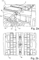
- a crawler belt 2 is shown at the second workstation 6.2, at which the outer chain connectors 8a are pulled off the crawler belt 2.
- two lateral openings 8.1 and an upper through opening 8.2 of the outer chain connector 8a are used.
- the chain cushions 8b are shown, which only on, in the Figures 7 and 8th shown, third workplace 6.3 are deducted.
- the outer chain connectors 8a are mounted on the crawler belt 2 on locating pins 9a which are attached to the base body 9b of the crawler belt 2.
- the inner chain connectors 8c and the outer chain connectors 8a are shown in FIG Figure 2b shown.
- the inner chain connectors 8c are already released and dismantled at the first workstation 6.1, which is arranged on the lower roller conveyor 3.1.
- the illustrated inner chain connector 8c is fixed to the crawler belt 2 by means of a force-fitting and / or form-fitting connection element. After releasing the connecting element, the section of the inner chain connector 8c located on the upper side of the crawler belt 2 can be removed.
- the section of the inner chain connector 8c arranged on the underside of the crawler belt 2 falls into a compartment provided for this purpose, which is arranged below the lower roller conveyor 3.1 and can be pulled out like a drawer.
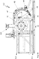
- the drive units 4 are in the Figures 3 to 5 pictured. In the Figures 3 and 4th are the drive units 4.2, 4.3 and in assigned to the deflection devices 5.1, 5.2 Fig. 5 the drive unit 4.1 assigned to the feed area is shown.
- FIG Fig. 3 A representation from the side of a drive unit 4 for moving the crawler belt 2 over the roller conveyor 3 is shown in FIG Fig. 3 pictured.
- a drive unit 4 corresponds to the second and third drive units 4.2, 4.3 in this exemplary embodiment.
- the core piece here is a pinion drum 10 on which two outer drive wheels 11 and two inner drive wheels 12 are mounted.
- the drive wheels 11, 12 can be engaged in the crawler belt 2 and move the crawler chain 2 over the rollably mounted rollers of the roller conveyor 3.
- the outer drive wheels 11 have a larger diameter than the inner drive wheels 12.
- the drive unit 4.2, 4.3 is for two different types configured of crawler tracks 2 without having to dismantle and reassemble the drive wheels 11, 12 when another type of crawler belt 2 is to be conveyed.
- the pinion drum 10 is lowered sufficiently so that the inner drive wheels 12 engage in the crawler belt 2.
- the outer drive wheels 11 then lower down next to the lower roller conveyor 3.1, so that the outer drive wheels 11 do not hinder the transport of the crawler belt 2.
- the pinion drum 10 is raised accordingly so that the outer drive wheels 11 engage in the crawler belt 2 and drive it.
- the inner drive wheels 12 are then located above the crawler belt 2 so that the crawler belt drive is not disturbed.
- the pinion drum 10 is attached to vertical supports 13 which are mounted on a horizontal support 14. By means of the vertical support 13, the pinion drum 10 hangs below the horizontal support 14, which is attached within a frame of the drive unit 15.
- the horizontal support 14 is arranged here between two vertically extending columns of the frame 15. Between the frame 15 and the vertical support 13, at the level of the pinion drum 10 on each side, there is a spacer plate 16 to secure the position of the pinion drum 10 and thus the outer and inner drive wheels 11, 12, whereby an even conveyance of the crawler belt 2 is achieved.
- the height adjustment of the outer and inner drive wheels 11, 12 for adaptation to different types of track chains is achieved by adjusting the height of the horizontal beam 14, which is connected to the frame 15 of the drive unit 4.2, 4.3 via a threaded rod 17.
- a hand wheel 18 with which the corresponding height can be set is arranged on the threaded rod, so that the threaded rod 17 is rotated up or down about its axis.
- the associated horizontal support 14 and the attached pinion drum 10 with the outer and inner drive wheels 11, 12 thus move up or down.
- the handwheel 18 By operating the handwheel 18, the height of the drive wheels 11, 12 of the drive unit 4.2, 4.3 can be adjusted in accordance with the crawler belt 2 to be transported.
- FIG. 3 is a perspective view of the embodiment of FIG Fig. 3 illustrated drive unit 4.2, 4.3.
- a footboard 19 is arranged on the frame of the drive unit 15 for better accessibility of the handwheel 18.
- Inside the pinion drum 10 is a drum motor which provides the power to move the crawler belt 2 by means of the drive wheels 11, 12.
- FIG Fig. 5 A perspective view of the drive unit 4.1, which is arranged at the feed area, with a unit for driving the pinion drum is shown in FIG Fig. 5 shown.
- a gear motor 20 is used to drive a chain wheel 21 and a roller chain 22 rotating around the chain wheel 21.
- the drive wheels 11, 12 are driven by the gear motor 20 via a chain wheel 21 and a roller chain 22.
- a footboard 19 is arranged on the frame of the drive unit 15, whereby the handwheel 18 is more easily reached.
- the outer chain connectors 8a are pulled off the crawler belt 2.
- an in Figure 6a shown puller 23 is used.
- the extraction tool 23 has a tool slide 24 which forms the frame for receiving the exchangeable parts of the extraction tool 23.
- a hydraulic cylinder 25 is attached below the tool slide 24 and provides the thrust for the interaction of a pulling bolt 26 and two thrust bolts 27.
- the push bolts 27 are fastened on a plate 28.
- the appropriate pulling bolt 26 and the suitable plate 28 with pre-assembled pushing bolts 27 are locked on the tool slide 24 of the pulling tool 23.
- the plate 28 is screwed to the tool slide 24 and the pulling bolt 26 is secured to the tool slide 24 with the aid of a split pin.
- the pull-off bolt 26 is inserted into the upper through-opening 8.2 of the outer chain connector 8a and locked on the puller 23 by means of the split pin.
- the push bolts 27 are then to the in the Fig.
- the removal tool 23 is movably supported horizontally along the axis of the push bolts 27 or along the direction of the removal process in a sliding guide.
- the thrust of the push bolts 27 after actuation of the hydraulic cylinder 25 generates a force which reduces the distance between the plate 28 and the pulling bolt 26. Since the position of the push bolts 27 in a horizontal direction due to the stuck Locating bolt 9a is limited, the existing thrust ensures that the outer chain connector 8a is pulled off the track 2 by means of the pulling bolt 26.
- the pulling tool 23 is also suitable for mounting an outer chain link 8a.
- the pulling tool 23 is used for the process of sliding a, for example, into Fig. 2a
- the outer chain connector 8a shown is fixed in the horizontal direction.
- the pulling tool 23 is secured on the sliding guide in a recess 29 of the tool slide 24 by means of a split pin.
- the tool slide is then fixed horizontally.
- the selection of one of the recesses 29 depends on the width of the crawler belt 2.
- the press-in adapter 30 shown is arranged on the pulling tool 23 in such a way that the push bolts 27 engage in the openings of the press-in adapter 30.
- the outer chain connector 8a to be mounted is arranged in front of the crawler belt 2 so that it is located with the lateral openings 8.1 in front of the locating pins 9a of the crawler belt 2 on which it is to be installed.
- the piston rod pushes the plate 28, the press-in adapter 30 mounted in front of it and the outer chain connector 8a positioned in front of the press-in adapter 20 in the direction of the crawler belt 2.
- the outer chain connector 8a is thereby pushed onto the locating pins 9a of the crawler belt 2 and can then be a fastening element, which is guided through the upper through opening 8.2, can be fastened to the crawler belt 2.
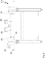
- Fig. 7 a possible configuration of the third work station 6.3 is shown, to which the chain cushions 8b can be dismantled and mounted, that is, the chain cushions 8b are pulled off the crawler belt 2 and pushed back onto it.
- a structure 32 is mounted on a frame 31, which is used to hold tools.
- the force for pulling off or pushing on the chain pads 8b is determined by one of two Hydraulic cylinders 33, each with an assigned piston 34, are made available, which are arranged on the structure 32 for the tool holder.
- a tool holding plate 35 and a bolt holding plate 36 are located on the structure 32, on which the elements or tools that are not required are advantageously stored in an easily accessible manner directly at the third work station 6.3.
- a position holder 37 is preferably also attached to the structure 32 for the tool holder.
- the position holder 37 spatially limits the end area of the crawler belt 2 upwards and thus prevents the end area from straightening up too much in the vertical direction.
- This position holder 37 thus acts from above on the bulge generated because of the chain pretensioning at the ends of the crawler belt 2 and holds the crawler belt 2 below.
- the aforementioned hydraulic cylinders 33 with pistons 34 are fastened to a tool slide 38, which is also arranged on the structure 32 for holding the tool, in such a way that the tool slide 38 can also be moved by means of the hydraulic system.
- a pull-off element 39 and a press-on element 40 are fixed on the tool slide.
- the pulling element 39 engages on the side of the chain cushion 8b to be pulled off opposite the pulling direction, i.e. between the two opposing chain cushions 8b, so that the pulling element 39 forces the unlocked chain cushions 8b in the pulling direction from the track 2 can slide down.
- a piston rod connected to the piston 34 lies on the base body 9b, which is shown in FIG Fig. 2a is shown, so on a fixed section of the crawler belt 2. Due to a hydraulic force, the tool slide 38 connected to the hydraulic cylinder 33 moves together with the puller element 39 in the direction of the piston rod in such a way that the horizontal distance between the piston rod and the puller element 39 is reduced.
- the horizontal distance is a distance that is independent of the height difference between the two objects. If the horizontal distance is reduced, the height difference, i.e. the vertical distance, is retained.
- the tool carriage 38 moves together with the pulling element 39 in the pulling direction towards the piston 34 and the piston rod and pulls the chain pad 8b off the crawler chain 2.
- FIG. 8 A representation of the third work station 6.3 from the side is in Fig. 8 shown.
- the tool slide 38 is integrated into the structure 32 in such a way that it is covered by the structure in this figure.
- the removal element 39 which is arranged on the side of the chain cushion 8b to be removed, cooperates with the piston 34 on the same side.
- the principle of pushing on the chain pads 8b largely corresponds to that of the removal process.
- the press-on element 40 which is arranged on the side of the chain cushion 8b to be pressed on, interacts with the piston 34 on the opposite side.
- the press-on element 40 is arranged next to a chain cushion 8b that is to be slid on in such a way that the press-on element 40 is pulled in the direction of the actuated opposite hydraulic cylinder 33 when the hydraulic system is actuated and the chain cushion 8b is pressed onto the crawler belt 2.
- the opposite piston 34 is on the opposite side of the in Fig. 2a illustrated base body 9b of the crawler belt 2.
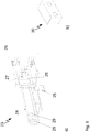
- the area of the chain repair device 1 is shown in which the second deflection device 5.2 is arranged.
- the special feature of the second deflection device 5.2 is a switching mechanism by means of a swivel arm 41, which allows to switch between two modes.
- the crawler belt 2 In the so-called “zero position”, which in Fig. 9 is shown, the crawler belt 2, not shown here, can be guided on the lower roller conveyor 3.1 under the second deflection device 5.2, whereas in the so-called “Circulation mode", which is in Fig. 10 it is shown that the crawler belt 2 can be guided from the upper roller conveyor 3.2 to the lower roller conveyor 3.1 and vice versa along the crawler belt direction of rotation 42.
- the path under the second circulating device 5.2 In the circulating mode, the path under the second circulating device 5.2 is blocked by the swivel arm 41, which is why it is necessary to switch the deflecting device 5.2 to the zero position in order to insert a crawler belt 2 into the chain repair
- the pivot arm 41 is rotatably mounted about a pivot axis 43 in such a way that the center of gravity of the pivot arm is arranged in the pivot axis 43. Accordingly, the heavy assembly can be moved by means of a tension spring 44 with little effort.
- the tension spring 44 is in the mode of FIG Fig. 9 "Zero position" shown, in which the crawler belt 2 can be moved over the lower roller conveyor 3.1 in the retraction direction 45 into the chain repair device 1 and in the extension direction 46 out of the chain repair device 1, relaxed. Since the pivot arm 41 has its center of gravity in the pivot axis 43, the pivot arm 41 folds down under the weight of the crawler belt 2 pushed into the second deflection device 5.2 by the upper roller conveyor 3.2.
- the track 2 is conveyed by means of the third drive unit 4.3 arranged next to the second deflection device 5.2.
- Drive wheels 11 for engaging in the crawler belt 2 are arranged on the third drive unit 4.3.
Landscapes
- Engineering & Computer Science (AREA)
- Mechanical Engineering (AREA)
- Chemical & Material Sciences (AREA)
- Combustion & Propulsion (AREA)
- Transportation (AREA)
- Chain Conveyers (AREA)
- Automobile Manufacture Line, Endless Track Vehicle, Trailer (AREA)
- Hand Tools For Fitting Together And Separating, Or Other Hand Tools (AREA)
Claims (15)
- Dispositif de remise en état de chaînes (1) pour l'usinage de chenilles (2), comprenant- un transporteur à rouleaux supérieur passif (3.2) et un transporteur à rouleaux inférieur passif (3.1) disposé en dessous de lui,- un premier dispositif de renvoi (5.1) pour le renvoi de la chenille (2) du transporteur à rouleaux inférieur (3.1) au transporteur à rouleaux supérieur (3.2) et inversement avec module d'entraînement associé (4.2),- un second dispositif de renvoi (5.2) pour le renvoi de la chenille (2) du transporteur à rouleaux supérieur (3.2) au transporteur à rouleaux inférieur (3.1) et inversement avec module d'entraînement associé (4.3),- dans lequel les transporteurs à rouleaux supérieur et inférieur (3.2, 3.1) sont réalisés en formant un circuit d'acheminement de chenilles avec les dispositifs de renvoi (5.1, 5.2) et que- au moins un poste de travail (6.2) pour le montage et démontage de constituants de la chenille (2) est disposé au sein du circuit d'acheminement de chenilles,caractérisé en ce que
une région d'alimentation et de jetée élargissant le transporteur à rouleaux inférieur (3.1) pour la chenille (2) avec un module d'entraînement associé (4.1) est intégrée dans le dispositif de remise en état de chaînes. - Dispositif de remise en état de chaînes (1) selon la revendication 1, caractérisé en ce que le module d'entraînement actif (4.1, 4.2, 4.3) est réalisé à partir d'un tambour à pignon (10) avec des roues d'entraînement (11, 12) disposées sur lui.
- Dispositif de remise en état de chaînes (1) selon la revendication 2, caractérisé en ce que deux roues d'entraînement identiques (11) sont à chaque fois disposées de manière écartée au sein du module d'entraînement actif (4.1, 4.2, 4.3) sur le tambour à pignon (10), lesquelles sont réalisées de manière à pouvoir être engrenées dans la chenille (2) de telle sorte que lors d'un engrènement des roues d'entraînement (11) dans la chenille (2), une rotation des roues d'entraînement (11) entraîne un coulissement de la chenille (2).
- Dispositif de remise en état de chaînes (1) selon une des revendications 2 ou 3, caractérisé en ce que sur le module d'entraînement (4.1, 4.2, 4.3), plusieurs paires de roues d'entraînement (11, 12) de taille différente sont disposées sur le tambour à pignon de manière écartée l'une de l'autre, symétriquement par rapport au milieu du tambour à pignon (10), dans lequel le diamètre des roues d'entraînement (11, 12) croît de l'intérieur vers l'extérieur.
- Dispositif de remise en état de chaînes (1) selon une des revendications 2 à 4, caractérisé en ce que les tambours à pignon (10) des modules d'entraînement (4.1, 4.2, 4.3) sont réalisés de manière réglable en hauteur pour l'adaptation à différents types de chenilles.
- Dispositif de remise en état de chaînes (1) selon une des revendications 2 à 5, caractérisé en ce que les tambours à pignon (10) des modules d'entraînement (4.2, 4.3) associés aux dispositifs de renvoi (5.1, 5.2) sont réalisés de manière réglable en hauteur de telle sorte que les roues d'entraînement (11, 12) disposées sur le tambour à pignon (10) s'engrènent dans une position supérieure dans la chenille (2) positionnée sur le transporteur à rouleaux supérieur (3.2) et dans une position inférieure dans la chenille (2) positionnée sur le transporteur à rouleaux inférieur (3.1).
- Dispositif de remise en état de chaînes (1) selon une des revendications 2 à 6, caractérisé en ce que les roues d'entraînement (11, 12) des modules d'entraînement (4.1, 4.2, 4.3) sont réalisées de manière rotative dans deux directions opposées.
- Dispositif de remise en état de chaînes (1) selon une des revendications 1 à 7, caractérisé en ce qu'un outil de retrait motorisé (23) pour le retrait des connecteurs de chaîne extérieurs (8a) de la chenille (2) et pour le nouvel enfilement des connecteurs de chaîne extérieurs (8a) sur la chenille (2) est disposé à un poste de travail (6.2).
- Dispositif de remise en état de chaînes (1) selon la revendication 8, caractérisé en ce que l'outil de retrait motorisé (23) présente un chariot porte-outil (24) avec deux boulons de poussée parallèles (27) en forme de barre, disposés sur le chariot porte-outil (24), orientés horizontalement dans la direction de retrait ainsi qu'un boulon de retrait (26) en forme de barre, pouvant être fixé au chariot porte-outil (24), orienté verticalement, dans lequel les boulons de poussée (27) sont connectés par le biais d'un moteur au chariot porte-outil (24) avec transmission de force de telle sorte que les boulons de poussée (27) se déplacent en direction axiale en raison du travail du moteur et l'écart horizontal entre les deux boulons de poussée (27) et le boulon de retrait (26) se réduit de ce fait.
- Dispositif de remise en état de chaînes (1) selon une des revendications 1 à 9, caractérisé en ce qu'un élément de retrait orienté verticalement (39) pour le retrait des rembourrages de chaîne (8b) est disposé à un poste de travail (6.3), dans lequel l'élément de retrait (39) est connecté à un pendant (34) en forme de barre, orienté horizontalement dans la direction du processus de retrait avec transmission de force de telle sorte que l'écart horizontal entre l'élément de retrait (39) et le pendant (34) peut être réduit par le travail d'un moteur.
- Dispositif de remise en état de chaînes (1) selon une des revendications 1 à 10, caractérisé en ce qu'un élément d'engagement par pression (40) orienté verticalement pour l'engagement par pression des rembourrages de chaîne (8b) est disposé à un poste de travail (6.3), dans lequel l'élément d'engagement par pression (40) est connecté à un pendant (34) en forme de barre, orienté horizontalement, à l'encontre de la direction du processus de retrait avec transmission de force de telle sorte que l'écart entre l'élément d'engagement par pression (40) et le pendant (34) peut être réduit par le travail d'un moteur.
- Dispositif de remise en état de chaînes (1) selon la revendication 10, caractérisé en ce que le moteur est un moteur hydraulique et le pendant (34) est un piston (34), dans lequel l'élément de retrait (39) est connecté de manière rigide à un cylindre hydraulique (33) coopérant avec le piston (34) de telle sorte qu'un déplacement du cylindre hydraulique (33) par rapport au piston (34) provoque en raison de la force générée par voie hydraulique dans le cylindre hydraulique (33) un déplacement de l'élément de retrait (39) en direction du piston (34).
- Dispositif de remise en état de chaînes (1) selon la revendication 11, caractérisé en ce que le moteur est un moteur hydraulique et le pendant (34) est un piston (34), dans lequel l'élément d'engagement par pression (40) est connecté de manière rigide à un cylindre hydraulique (33) coopérant avec le piston (34) de telle sorte qu'un déplacement du cylindre hydraulique (33) provoque en raison de la force générée par voie hydraulique dans le cylindre hydraulique (33) un déplacement de l'élément d'engagement par pression (40) en direction du piston (34).
- Dispositif de remise en état de chaînes (1) selon une des revendications 1 à 13, caractérisé en ce que le second dispositif de renvoi (5.2) présente un bras pivotant (41) dont le centre de gravité peut être équilibré de telle sorte que le bras pivotant (41) est réalisé de manière à pouvoir être rabattu automatiquement de manière réversible par le poids de la chenille (2) pour le changement entre une position neutre et une position de rotation.
- Dispositif de remise en état de chaînes (1) selon la revendication 14, caractérisé en ce que le mécanisme de rabattement du bras pivotant (41) de la position de rotation de retour à la position neutre est assisté au moyen de la résilience d'un ressort de traction (44) fixé au bras pivotant (41).
Applications Claiming Priority (1)
| Application Number | Priority Date | Filing Date | Title |
|---|---|---|---|
| DE202017102228.5U DE202017102228U1 (de) | 2017-04-13 | 2017-04-13 | Ketteninstandsetzungsvorrichtung |
Publications (2)
| Publication Number | Publication Date |
|---|---|
| EP3388200A1 EP3388200A1 (fr) | 2018-10-17 |
| EP3388200B1 true EP3388200B1 (fr) | 2021-01-20 |
Family
ID=59522576
Family Applications (1)
| Application Number | Title | Priority Date | Filing Date |
|---|---|---|---|
| EP18166933.4A Active EP3388200B1 (fr) | 2017-04-13 | 2018-04-12 | Dispositif de remise en état de chaînes |
Country Status (2)
| Country | Link |
|---|---|
| EP (1) | EP3388200B1 (fr) |
| DE (1) | DE202017102228U1 (fr) |
Families Citing this family (1)
| Publication number | Priority date | Publication date | Assignee | Title |
|---|---|---|---|---|
| CN112009587A (zh) * | 2020-09-15 | 2020-12-01 | 贺超 | 一种便于使用的机动车履带拆卸工具 |
Family Cites Families (5)
| Publication number | Priority date | Publication date | Assignee | Title |
|---|---|---|---|---|
| GB779523A (en) * | 1953-10-06 | 1957-07-24 | Maltby S Engineers Ltd | Method of grinding the components of the endless tracks of tracked vehicles and a machine for carrying out the method |
| US4167058A (en) * | 1977-10-31 | 1979-09-11 | Wolff Manufacturing Company | Conveyor and shoe lifting assembly for tractor tracks |
| DE8025249U1 (de) | 1980-09-20 | 1980-12-18 | Krauss-Maffei Ag, 8000 Muenchen | Vorrichtung zum ausziehen von kettenpolstern aus gleisketten |
| FR2811283B1 (fr) | 2000-07-07 | 2002-10-11 | Giat Ind Sa | Dispositif d'aide au chenillage |
| FR3022521B1 (fr) * | 2014-06-20 | 2017-10-13 | Nexter Systems | Dispositif de manutention pour une chenille de vehicule, dispositif et procede de changement de semelles de chenille mettant en oeuvre un tel dispositif de manutention. |
-
2017
- 2017-04-13 DE DE202017102228.5U patent/DE202017102228U1/de active Active
-
2018
- 2018-04-12 EP EP18166933.4A patent/EP3388200B1/fr active Active
Non-Patent Citations (1)
| Title |
|---|
| None * |
Also Published As
| Publication number | Publication date |
|---|---|
| DE202017102228U1 (de) | 2017-07-13 |
| EP3388200A1 (fr) | 2018-10-17 |
Similar Documents
| Publication | Publication Date | Title |
|---|---|---|
| DE102007008480A1 (de) | Bearbeitungslinie | |
| EP2881187B1 (fr) | Planeuse à cylindres et procédé d'inspection, de maintenance et de remise en état d'une planeuse à cylindres | |
| EP3388200B1 (fr) | Dispositif de remise en état de chaînes | |
| EP3406362A1 (fr) | Machine à étirer à chenilles et procédé d'étirage | |
| DE10216258B4 (de) | Triebwerkstand | |
| WO2017202532A1 (fr) | Machine à dresser à cylindres comprenant des cylindres à dresser supérieurs et inférieurs et procédé permettant de simplifier et d'accélérer l'inspection, la maintenance et l'entretien des cylindres à dresser supérieurs d'une machine à dresser à cylindres | |
| DE2805635C2 (de) | Vorrichtung zum seitlichen Ausscheren von Kraftfahrzeugen | |
| EP1572386B1 (fr) | Laminoir comprenant des moyens pour le changement des cylindres | |
| EP1201350B1 (fr) | Presse pour jeu de roues pour monter ou démonter par pressage de roues, disques de frein ou similaires sur des essieux de véhicules ferroviaires | |
| DE2021820C3 (de) | Unterflur-Radsatzdrehmaschine | |
| EP1212153B1 (fr) | Cage de laminoir | |
| EP3548206B1 (fr) | Système de serrage permettant de fixer un bloc réfrigérant à un élément de support périphérique d'une machine de coulée sur chenilles et procédé de fixation ou de libération d'un bloc réfrigérant vis à vis d'un élément de support périphérique d'une machine de coulée sur chenilles | |
| WO2006045284A1 (fr) | Dispositif de changement d'outillage automatique | |
| EP0484783B1 (fr) | Dispositif pour le haubanage et l'équilibrage du porte-outil de pressage et de la boîte de manivelle d'une presse à refouler | |
| EP2563532B1 (fr) | Dispositif de manutention et/ou de transport, au moins par paires, de cylindres de soutien et/ou de cylindres de travail d'une cage de laminoir | |
| DE202016006565U1 (de) | Auf einem Gleis verfahrbare Maschine | |
| DE3132712C2 (de) | Rohrschrägwalzgerüst | |
| DE2319729C3 (de) | Vorrichtung zum Auswechseln der Arbeitswalzen eines Walzgerüstes | |
| DE8236153U1 (de) | Rahmenpresse | |
| DE19833113A1 (de) | Lagerung für einen Zylinder in einer Druckmaschine | |
| DE2823139C2 (de) | Vorrichtung zum Wechseln der Kegelwalzen eines Schrägwalzgerüstes mit Planetenantrieb | |
| AT522864B1 (de) | Seilsäge | |
| DE19632217C1 (de) | Maschine zum beidseitigen Beschleifen von Steinen oder Kunststeinen oder dgl. | |
| DE2154196C3 (de) | Vortriebsmaschine | |
| DE2834578C2 (de) | Vortriebsmaschine zum Auffahren von Tunneln, Stollen, Strecken o.dgl. |
Legal Events
| Date | Code | Title | Description |
|---|---|---|---|
| PUAI | Public reference made under article 153(3) epc to a published international application that has entered the european phase |
Free format text: ORIGINAL CODE: 0009012 |
|
| STAA | Information on the status of an ep patent application or granted ep patent |
Free format text: STATUS: THE APPLICATION HAS BEEN PUBLISHED |
|
| AK | Designated contracting states |
Kind code of ref document: A1 Designated state(s): AL AT BE BG CH CY CZ DE DK EE ES FI FR GB GR HR HU IE IS IT LI LT LU LV MC MK MT NL NO PL PT RO RS SE SI SK SM TR |
|
| AX | Request for extension of the european patent |
Extension state: BA ME |
|
| RIN1 | Information on inventor provided before grant (corrected) |
Inventor name: EXLER, STEFFEN Inventor name: BALTING, TORSTEN Inventor name: NIEMTSCHKE, GUNTER Inventor name: KLUGE, PHILIPP |
|
| STAA | Information on the status of an ep patent application or granted ep patent |
Free format text: STATUS: REQUEST FOR EXAMINATION WAS MADE |
|
| 17P | Request for examination filed |
Effective date: 20190415 |
|
| RBV | Designated contracting states (corrected) |
Designated state(s): AL AT BE BG CH CY CZ DE DK EE ES FI FR GB GR HR HU IE IS IT LI LT LU LV MC MK MT NL NO PL PT RO RS SE SI SK SM TR |
|
| RAP1 | Party data changed (applicant data changed or rights of an application transferred) |
Owner name: MWK DEFENCE GMBH |
|
| GRAP | Despatch of communication of intention to grant a patent |
Free format text: ORIGINAL CODE: EPIDOSNIGR1 |
|
| STAA | Information on the status of an ep patent application or granted ep patent |
Free format text: STATUS: GRANT OF PATENT IS INTENDED |
|
| INTG | Intention to grant announced |
Effective date: 20201021 |
|
| GRAS | Grant fee paid |
Free format text: ORIGINAL CODE: EPIDOSNIGR3 |
|
| GRAA | (expected) grant |
Free format text: ORIGINAL CODE: 0009210 |
|
| STAA | Information on the status of an ep patent application or granted ep patent |
Free format text: STATUS: THE PATENT HAS BEEN GRANTED |
|
| AK | Designated contracting states |
Kind code of ref document: B1 Designated state(s): AL AT BE BG CH CY CZ DE DK EE ES FI FR GB GR HR HU IE IS IT LI LT LU LV MC MK MT NL NO PL PT RO RS SE SI SK SM TR |
|
| REG | Reference to a national code |
Ref country code: GB Ref legal event code: FG4D Free format text: NOT ENGLISH |
|
| REG | Reference to a national code |
Ref country code: CH Ref legal event code: EP |
|
| REG | Reference to a national code |
Ref country code: DE Ref legal event code: R096 Ref document number: 502018003692 Country of ref document: DE |
|
| REG | Reference to a national code |
Ref country code: AT Ref legal event code: REF Ref document number: 1355972 Country of ref document: AT Kind code of ref document: T Effective date: 20210215 |
|
| REG | Reference to a national code |
Ref country code: IE Ref legal event code: FG4D Free format text: LANGUAGE OF EP DOCUMENT: GERMAN |
|
| REG | Reference to a national code |
Ref country code: NL Ref legal event code: MP Effective date: 20210120 |
|
| REG | Reference to a national code |
Ref country code: LT Ref legal event code: MG9D |
|
| PG25 | Lapsed in a contracting state [announced via postgrant information from national office to epo] |
Ref country code: GR Free format text: LAPSE BECAUSE OF FAILURE TO SUBMIT A TRANSLATION OF THE DESCRIPTION OR TO PAY THE FEE WITHIN THE PRESCRIBED TIME-LIMIT Effective date: 20210421 Ref country code: FI Free format text: LAPSE BECAUSE OF FAILURE TO SUBMIT A TRANSLATION OF THE DESCRIPTION OR TO PAY THE FEE WITHIN THE PRESCRIBED TIME-LIMIT Effective date: 20210120 Ref country code: HR Free format text: LAPSE BECAUSE OF FAILURE TO SUBMIT A TRANSLATION OF THE DESCRIPTION OR TO PAY THE FEE WITHIN THE PRESCRIBED TIME-LIMIT Effective date: 20210120 Ref country code: BG Free format text: LAPSE BECAUSE OF FAILURE TO SUBMIT A TRANSLATION OF THE DESCRIPTION OR TO PAY THE FEE WITHIN THE PRESCRIBED TIME-LIMIT Effective date: 20210420 Ref country code: PT Free format text: LAPSE BECAUSE OF FAILURE TO SUBMIT A TRANSLATION OF THE DESCRIPTION OR TO PAY THE FEE WITHIN THE PRESCRIBED TIME-LIMIT Effective date: 20210520 Ref country code: NO Free format text: LAPSE BECAUSE OF FAILURE TO SUBMIT A TRANSLATION OF THE DESCRIPTION OR TO PAY THE FEE WITHIN THE PRESCRIBED TIME-LIMIT Effective date: 20210420 Ref country code: LT Free format text: LAPSE BECAUSE OF FAILURE TO SUBMIT A TRANSLATION OF THE DESCRIPTION OR TO PAY THE FEE WITHIN THE PRESCRIBED TIME-LIMIT Effective date: 20210120 |
|
| PG25 | Lapsed in a contracting state [announced via postgrant information from national office to epo] |
Ref country code: SE Free format text: LAPSE BECAUSE OF FAILURE TO SUBMIT A TRANSLATION OF THE DESCRIPTION OR TO PAY THE FEE WITHIN THE PRESCRIBED TIME-LIMIT Effective date: 20210120 Ref country code: RS Free format text: LAPSE BECAUSE OF FAILURE TO SUBMIT A TRANSLATION OF THE DESCRIPTION OR TO PAY THE FEE WITHIN THE PRESCRIBED TIME-LIMIT Effective date: 20210120 Ref country code: LV Free format text: LAPSE BECAUSE OF FAILURE TO SUBMIT A TRANSLATION OF THE DESCRIPTION OR TO PAY THE FEE WITHIN THE PRESCRIBED TIME-LIMIT Effective date: 20210120 Ref country code: PL Free format text: LAPSE BECAUSE OF FAILURE TO SUBMIT A TRANSLATION OF THE DESCRIPTION OR TO PAY THE FEE WITHIN THE PRESCRIBED TIME-LIMIT Effective date: 20210120 |
|
| PG25 | Lapsed in a contracting state [announced via postgrant information from national office to epo] |
Ref country code: IS Free format text: LAPSE BECAUSE OF FAILURE TO SUBMIT A TRANSLATION OF THE DESCRIPTION OR TO PAY THE FEE WITHIN THE PRESCRIBED TIME-LIMIT Effective date: 20210520 |
|
| REG | Reference to a national code |
Ref country code: DE Ref legal event code: R097 Ref document number: 502018003692 Country of ref document: DE |
|
| PG25 | Lapsed in a contracting state [announced via postgrant information from national office to epo] |
Ref country code: EE Free format text: LAPSE BECAUSE OF FAILURE TO SUBMIT A TRANSLATION OF THE DESCRIPTION OR TO PAY THE FEE WITHIN THE PRESCRIBED TIME-LIMIT Effective date: 20210120 Ref country code: CZ Free format text: LAPSE BECAUSE OF FAILURE TO SUBMIT A TRANSLATION OF THE DESCRIPTION OR TO PAY THE FEE WITHIN THE PRESCRIBED TIME-LIMIT Effective date: 20210120 Ref country code: SM Free format text: LAPSE BECAUSE OF FAILURE TO SUBMIT A TRANSLATION OF THE DESCRIPTION OR TO PAY THE FEE WITHIN THE PRESCRIBED TIME-LIMIT Effective date: 20210120 |
|
| PLBE | No opposition filed within time limit |
Free format text: ORIGINAL CODE: 0009261 |
|
| STAA | Information on the status of an ep patent application or granted ep patent |
Free format text: STATUS: NO OPPOSITION FILED WITHIN TIME LIMIT |
|
| PG25 | Lapsed in a contracting state [announced via postgrant information from national office to epo] |
Ref country code: MC Free format text: LAPSE BECAUSE OF FAILURE TO SUBMIT A TRANSLATION OF THE DESCRIPTION OR TO PAY THE FEE WITHIN THE PRESCRIBED TIME-LIMIT Effective date: 20210120 Ref country code: RO Free format text: LAPSE BECAUSE OF FAILURE TO SUBMIT A TRANSLATION OF THE DESCRIPTION OR TO PAY THE FEE WITHIN THE PRESCRIBED TIME-LIMIT Effective date: 20210120 Ref country code: SK Free format text: LAPSE BECAUSE OF FAILURE TO SUBMIT A TRANSLATION OF THE DESCRIPTION OR TO PAY THE FEE WITHIN THE PRESCRIBED TIME-LIMIT Effective date: 20210120 Ref country code: DK Free format text: LAPSE BECAUSE OF FAILURE TO SUBMIT A TRANSLATION OF THE DESCRIPTION OR TO PAY THE FEE WITHIN THE PRESCRIBED TIME-LIMIT Effective date: 20210120 |
|
| 26N | No opposition filed |
Effective date: 20211021 |
|
| PG25 | Lapsed in a contracting state [announced via postgrant information from national office to epo] |
Ref country code: LU Free format text: LAPSE BECAUSE OF NON-PAYMENT OF DUE FEES Effective date: 20210412 |
|
| REG | Reference to a national code |
Ref country code: BE Ref legal event code: MM Effective date: 20210430 |
|
| PG25 | Lapsed in a contracting state [announced via postgrant information from national office to epo] |
Ref country code: LI Free format text: LAPSE BECAUSE OF NON-PAYMENT OF DUE FEES Effective date: 20210430 Ref country code: AL Free format text: LAPSE BECAUSE OF FAILURE TO SUBMIT A TRANSLATION OF THE DESCRIPTION OR TO PAY THE FEE WITHIN THE PRESCRIBED TIME-LIMIT Effective date: 20210120 Ref country code: CH Free format text: LAPSE BECAUSE OF NON-PAYMENT OF DUE FEES Effective date: 20210430 Ref country code: ES Free format text: LAPSE BECAUSE OF FAILURE TO SUBMIT A TRANSLATION OF THE DESCRIPTION OR TO PAY THE FEE WITHIN THE PRESCRIBED TIME-LIMIT Effective date: 20210120 Ref country code: FR Free format text: LAPSE BECAUSE OF NON-PAYMENT OF DUE FEES Effective date: 20210430 |
|
| PG25 | Lapsed in a contracting state [announced via postgrant information from national office to epo] |
Ref country code: SI Free format text: LAPSE BECAUSE OF FAILURE TO SUBMIT A TRANSLATION OF THE DESCRIPTION OR TO PAY THE FEE WITHIN THE PRESCRIBED TIME-LIMIT Effective date: 20210120 |
|
| PG25 | Lapsed in a contracting state [announced via postgrant information from national office to epo] |
Ref country code: IT Free format text: LAPSE BECAUSE OF FAILURE TO SUBMIT A TRANSLATION OF THE DESCRIPTION OR TO PAY THE FEE WITHIN THE PRESCRIBED TIME-LIMIT Effective date: 20210120 Ref country code: IE Free format text: LAPSE BECAUSE OF NON-PAYMENT OF DUE FEES Effective date: 20210412 |
|
| PG25 | Lapsed in a contracting state [announced via postgrant information from national office to epo] |
Ref country code: IS Free format text: LAPSE BECAUSE OF FAILURE TO SUBMIT A TRANSLATION OF THE DESCRIPTION OR TO PAY THE FEE WITHIN THE PRESCRIBED TIME-LIMIT Effective date: 20210520 |
|
| PG25 | Lapsed in a contracting state [announced via postgrant information from national office to epo] |
Ref country code: BE Free format text: LAPSE BECAUSE OF NON-PAYMENT OF DUE FEES Effective date: 20210430 |
|
| GBPC | Gb: european patent ceased through non-payment of renewal fee |
Effective date: 20220412 |
|
| PG25 | Lapsed in a contracting state [announced via postgrant information from national office to epo] |
Ref country code: GB Free format text: LAPSE BECAUSE OF NON-PAYMENT OF DUE FEES Effective date: 20220412 |
|
| PG25 | Lapsed in a contracting state [announced via postgrant information from national office to epo] |
Ref country code: NL Free format text: LAPSE BECAUSE OF NON-PAYMENT OF DUE FEES Effective date: 20210120 Ref country code: CY Free format text: LAPSE BECAUSE OF FAILURE TO SUBMIT A TRANSLATION OF THE DESCRIPTION OR TO PAY THE FEE WITHIN THE PRESCRIBED TIME-LIMIT Effective date: 20210120 |
|
| PG25 | Lapsed in a contracting state [announced via postgrant information from national office to epo] |
Ref country code: HU Free format text: LAPSE BECAUSE OF FAILURE TO SUBMIT A TRANSLATION OF THE DESCRIPTION OR TO PAY THE FEE WITHIN THE PRESCRIBED TIME-LIMIT; INVALID AB INITIO Effective date: 20180412 |
|
| PGFP | Annual fee paid to national office [announced via postgrant information from national office to epo] |
Ref country code: DE Payment date: 20230418 Year of fee payment: 6 |
|
| PG25 | Lapsed in a contracting state [announced via postgrant information from national office to epo] |
Ref country code: MK Free format text: LAPSE BECAUSE OF FAILURE TO SUBMIT A TRANSLATION OF THE DESCRIPTION OR TO PAY THE FEE WITHIN THE PRESCRIBED TIME-LIMIT Effective date: 20210120 |