EP3385930A1 - Verfahren und vorrichtung zur erzeugung von prognostizierten fahrzeuginformationen für fahrten auf dem fahrzeugstrassennetz - Google Patents
Verfahren und vorrichtung zur erzeugung von prognostizierten fahrzeuginformationen für fahrten auf dem fahrzeugstrassennetz Download PDFInfo
- Publication number
- EP3385930A1 EP3385930A1 EP16870593.7A EP16870593A EP3385930A1 EP 3385930 A1 EP3385930 A1 EP 3385930A1 EP 16870593 A EP16870593 A EP 16870593A EP 3385930 A1 EP3385930 A1 EP 3385930A1
- Authority
- EP
- European Patent Office
- Prior art keywords
- vehicle
- remote vehicle
- time point
- lane
- probability value
- Prior art date
- Legal status (The legal status is an assumption and is not a legal conclusion. Google has not performed a legal analysis and makes no representation as to the accuracy of the status listed.)
- Granted
Links
Images


Classifications
-
- G—PHYSICS
- G08—SIGNALLING
- G08G—TRAFFIC CONTROL SYSTEMS
- G08G1/00—Traffic control systems for road vehicles
- G08G1/01—Detecting movement of traffic to be counted or controlled
- G08G1/0104—Measuring and analyzing of parameters relative to traffic conditions
- G08G1/0137—Measuring and analyzing of parameters relative to traffic conditions for specific applications
- G08G1/0145—Measuring and analyzing of parameters relative to traffic conditions for specific applications for active traffic flow control
-
- G—PHYSICS
- G08—SIGNALLING
- G08G—TRAFFIC CONTROL SYSTEMS
- G08G1/00—Traffic control systems for road vehicles
- G08G1/16—Anti-collision systems
- G08G1/161—Decentralised systems, e.g. inter-vehicle communication
- G08G1/163—Decentralised systems, e.g. inter-vehicle communication involving continuous checking
-
- B—PERFORMING OPERATIONS; TRANSPORTING
- B60—VEHICLES IN GENERAL
- B60W—CONJOINT CONTROL OF VEHICLE SUB-UNITS OF DIFFERENT TYPE OR DIFFERENT FUNCTION; CONTROL SYSTEMS SPECIALLY ADAPTED FOR HYBRID VEHICLES; ROAD VEHICLE DRIVE CONTROL SYSTEMS FOR PURPOSES NOT RELATED TO THE CONTROL OF A PARTICULAR SUB-UNIT
- B60W30/00—Purposes of road vehicle drive control systems not related to the control of a particular sub-unit, e.g. of systems using conjoint control of vehicle sub-units
- B60W30/10—Path keeping
- B60W30/12—Lane keeping
-
- B—PERFORMING OPERATIONS; TRANSPORTING
- B60—VEHICLES IN GENERAL
- B60W—CONJOINT CONTROL OF VEHICLE SUB-UNITS OF DIFFERENT TYPE OR DIFFERENT FUNCTION; CONTROL SYSTEMS SPECIALLY ADAPTED FOR HYBRID VEHICLES; ROAD VEHICLE DRIVE CONTROL SYSTEMS FOR PURPOSES NOT RELATED TO THE CONTROL OF A PARTICULAR SUB-UNIT
- B60W30/00—Purposes of road vehicle drive control systems not related to the control of a particular sub-unit, e.g. of systems using conjoint control of vehicle sub-units
- B60W30/14—Adaptive cruise control
- B60W30/16—Control of distance between vehicles, e.g. keeping a distance to preceding vehicle
-
- B—PERFORMING OPERATIONS; TRANSPORTING
- B60—VEHICLES IN GENERAL
- B60W—CONJOINT CONTROL OF VEHICLE SUB-UNITS OF DIFFERENT TYPE OR DIFFERENT FUNCTION; CONTROL SYSTEMS SPECIALLY ADAPTED FOR HYBRID VEHICLES; ROAD VEHICLE DRIVE CONTROL SYSTEMS FOR PURPOSES NOT RELATED TO THE CONTROL OF A PARTICULAR SUB-UNIT
- B60W50/00—Details of control systems for road vehicle drive control not related to the control of a particular sub-unit, e.g. process diagnostic or vehicle driver interfaces
- B60W50/08—Interaction between the driver and the control system
- B60W50/12—Limiting control by the driver depending on vehicle state, e.g. interlocking means for the control input for preventing unsafe operation
-
- G—PHYSICS
- G01—MEASURING; TESTING
- G01S—RADIO DIRECTION-FINDING; RADIO NAVIGATION; DETERMINING DISTANCE OR VELOCITY BY USE OF RADIO WAVES; LOCATING OR PRESENCE-DETECTING BY USE OF THE REFLECTION OR RERADIATION OF RADIO WAVES; ANALOGOUS ARRANGEMENTS USING OTHER WAVES
- G01S19/00—Satellite radio beacon positioning systems; Determining position, velocity or attitude using signals transmitted by such systems
- G01S19/38—Determining a navigation solution using signals transmitted by a satellite radio beacon positioning system
- G01S19/39—Determining a navigation solution using signals transmitted by a satellite radio beacon positioning system the satellite radio beacon positioning system transmitting time-stamped messages, e.g. GPS [Global Positioning System], GLONASS [Global Orbiting Navigation Satellite System] or GALILEO
- G01S19/42—Determining position
- G01S19/50—Determining position whereby the position solution is constrained to lie upon a particular curve or surface, e.g. for locomotives on railway tracks
-
- G—PHYSICS
- G08—SIGNALLING
- G08G—TRAFFIC CONTROL SYSTEMS
- G08G1/00—Traffic control systems for road vehicles
- G08G1/01—Detecting movement of traffic to be counted or controlled
- G08G1/0104—Measuring and analyzing of parameters relative to traffic conditions
- G08G1/0108—Measuring and analyzing of parameters relative to traffic conditions based on the source of data
- G08G1/0112—Measuring and analyzing of parameters relative to traffic conditions based on the source of data from the vehicle, e.g. floating car data [FCD]
-
- G—PHYSICS
- G08—SIGNALLING
- G08G—TRAFFIC CONTROL SYSTEMS
- G08G1/00—Traffic control systems for road vehicles
- G08G1/01—Detecting movement of traffic to be counted or controlled
- G08G1/0104—Measuring and analyzing of parameters relative to traffic conditions
- G08G1/0125—Traffic data processing
- G08G1/0133—Traffic data processing for classifying traffic situation
-
- G—PHYSICS
- G08—SIGNALLING
- G08G—TRAFFIC CONTROL SYSTEMS
- G08G1/00—Traffic control systems for road vehicles
- G08G1/01—Detecting movement of traffic to be counted or controlled
- G08G1/0104—Measuring and analyzing of parameters relative to traffic conditions
- G08G1/0137—Measuring and analyzing of parameters relative to traffic conditions for specific applications
- G08G1/0141—Measuring and analyzing of parameters relative to traffic conditions for specific applications for traffic information dissemination
-
- G—PHYSICS
- G08—SIGNALLING
- G08G—TRAFFIC CONTROL SYSTEMS
- G08G1/00—Traffic control systems for road vehicles
- G08G1/07—Controlling traffic signals
-
- G—PHYSICS
- G08—SIGNALLING
- G08G—TRAFFIC CONTROL SYSTEMS
- G08G1/00—Traffic control systems for road vehicles
- G08G1/09—Arrangements for giving variable traffic instructions
-
- G—PHYSICS
- G08—SIGNALLING
- G08G—TRAFFIC CONTROL SYSTEMS
- G08G1/00—Traffic control systems for road vehicles
- G08G1/09—Arrangements for giving variable traffic instructions
- G08G1/0962—Arrangements for giving variable traffic instructions having an indicator mounted inside the vehicle, e.g. giving voice messages
- G08G1/0967—Systems involving transmission of highway information, e.g. weather, speed limits
- G08G1/096708—Systems involving transmission of highway information, e.g. weather, speed limits where the received information might be used to generate an automatic action on the vehicle control
- G08G1/096725—Systems involving transmission of highway information, e.g. weather, speed limits where the received information might be used to generate an automatic action on the vehicle control where the received information generates an automatic action on the vehicle control
-
- G—PHYSICS
- G08—SIGNALLING
- G08G—TRAFFIC CONTROL SYSTEMS
- G08G1/00—Traffic control systems for road vehicles
- G08G1/09—Arrangements for giving variable traffic instructions
- G08G1/0962—Arrangements for giving variable traffic instructions having an indicator mounted inside the vehicle, e.g. giving voice messages
- G08G1/0967—Systems involving transmission of highway information, e.g. weather, speed limits
- G08G1/096766—Systems involving transmission of highway information, e.g. weather, speed limits where the system is characterised by the origin of the information transmission
- G08G1/096775—Systems involving transmission of highway information, e.g. weather, speed limits where the system is characterised by the origin of the information transmission where the origin of the information is a central station
-
- G—PHYSICS
- G08—SIGNALLING
- G08G—TRAFFIC CONTROL SYSTEMS
- G08G1/00—Traffic control systems for road vehicles
- G08G1/09—Arrangements for giving variable traffic instructions
- G08G1/0962—Arrangements for giving variable traffic instructions having an indicator mounted inside the vehicle, e.g. giving voice messages
- G08G1/0967—Systems involving transmission of highway information, e.g. weather, speed limits
- G08G1/096766—Systems involving transmission of highway information, e.g. weather, speed limits where the system is characterised by the origin of the information transmission
- G08G1/096783—Systems involving transmission of highway information, e.g. weather, speed limits where the system is characterised by the origin of the information transmission where the origin of the information is a roadside individual element
-
- G—PHYSICS
- G08—SIGNALLING
- G08G—TRAFFIC CONTROL SYSTEMS
- G08G1/00—Traffic control systems for road vehicles
- G08G1/09—Arrangements for giving variable traffic instructions
- G08G1/0962—Arrangements for giving variable traffic instructions having an indicator mounted inside the vehicle, e.g. giving voice messages
- G08G1/0967—Systems involving transmission of highway information, e.g. weather, speed limits
- G08G1/096766—Systems involving transmission of highway information, e.g. weather, speed limits where the system is characterised by the origin of the information transmission
- G08G1/096791—Systems involving transmission of highway information, e.g. weather, speed limits where the system is characterised by the origin of the information transmission where the origin of the information is another vehicle
-
- G—PHYSICS
- G08—SIGNALLING
- G08G—TRAFFIC CONTROL SYSTEMS
- G08G1/00—Traffic control systems for road vehicles
- G08G1/16—Anti-collision systems
- G08G1/161—Decentralised systems, e.g. inter-vehicle communication
-
- G—PHYSICS
- G08—SIGNALLING
- G08G—TRAFFIC CONTROL SYSTEMS
- G08G1/00—Traffic control systems for road vehicles
- G08G1/16—Anti-collision systems
- G08G1/164—Centralised systems, e.g. external to vehicles
-
- B—PERFORMING OPERATIONS; TRANSPORTING
- B60—VEHICLES IN GENERAL
- B60W—CONJOINT CONTROL OF VEHICLE SUB-UNITS OF DIFFERENT TYPE OR DIFFERENT FUNCTION; CONTROL SYSTEMS SPECIALLY ADAPTED FOR HYBRID VEHICLES; ROAD VEHICLE DRIVE CONTROL SYSTEMS FOR PURPOSES NOT RELATED TO THE CONTROL OF A PARTICULAR SUB-UNIT
- B60W2556/00—Input parameters relating to data
-
- G—PHYSICS
- G08—SIGNALLING
- G08G—TRAFFIC CONTROL SYSTEMS
- G08G1/00—Traffic control systems for road vehicles
- G08G1/16—Anti-collision systems
- G08G1/167—Driving aids for lane monitoring, lane changing, e.g. blind spot detection
Definitions
- This disclosure relates to vehicle operation, including routing and navigation.
- a vehicle may include a control system that generates and maintains a route of travel and may control the vehicle to traverse the route of travel.
- an autonomous vehicle may be controlled autonomously, without direct human intervention, to traverse a route of travel from an origin to a destination. With both autonomous vehicles and non-autonomous vehicles, it is desirable to know where remote vehicles will be along that route.
- An aspect of the disclosed embodiments is a method of generating projected vehicle information for use in traversing a vehicle transportation network.
- the method comprises receiving, at a host vehicle, remote vehicle spatial state information for a remote vehicle, identifying vehicle transportation network information representing a portion of the vehicle transportation network based on the remote vehicle spatial state information, generating, by a processor in response to instructions stored on a non-transitory computer readable medium, at least one initial probability value based on a comparison of the remote vehicle spatial state information and the vehicle transportation network information at an initial time point, each initial probability value indicating a likelihood that the remote vehicle is following a single lane within the vehicle transportation network information, generating, for a plurality of time points including the initial time point, a deviation of the remote vehicle between adjacent values for the remote vehicle spatial state information relative to the vehicle transportation network information, updating, for each single lane and for each deviation, the likelihood that the remote vehicle is following the single lane using a new probability value based on the deviation, generating, for the remote vehicle, a trajectory using the likelihood as updated
- a host vehicle that includes a processor configured to execute instructions stored on a non-transitory computer readable medium to receive remote vehicle spatial state information for a remote vehicle, identify vehicle transportation network information representing a portion of the vehicle transportation network based on the remote vehicle spatial state information, generate at least one initial probability value based on a comparison of the remote vehicle spatial state information and the vehicle transportation network information at an initial time point, each initial probability value indicating a likelihood that the remote vehicle is following a single lane within the vehicle transportation network information, generate, for a plurality of time points including the initial time point, a deviation of the remote vehicle between adjacent values for the remote vehicle spatial state information relative to the vehicle transportation network information, update, for each single lane and for each deviation, the likelihood that the remote vehicle is following the single lane using a new probability value based on the deviation, generate, for the remote vehicle, a trajectory using the likelihood as updated, and traverse, using a host vehicle, the vehicle transportation network using the vehicle transportation network information and the trajectory for the remote vehicle.
- Yet another aspect of the disclosed embodiments is an apparatus including a non-transitory memory and a processor.
- the processor is configured to execute instructions stored on the non-transitory memory to receive remote vehicle spatial state information for a remote vehicle, identify vehicle transportation network information representing a portion of the vehicle transportation network based on the remote vehicle spatial state information, generate at least one initial probability value based on a comparison of the remote vehicle spatial state information and the vehicle transportation network information at an initial time point, each initial probability value indicating a likelihood that the remote vehicle is following a single lane within the vehicle transportation network information, generate, for a plurality of time points including the initial time point, a deviation of the remote vehicle between adjacent values for the remote vehicle spatial state information relative to the vehicle transportation network information, update, for each single lane and for each deviation, the likelihood that the remote vehicle is following the single lane using a new probability value based on the deviation, generate, for the remote vehicle, a trajectory using the likelihood as updated, and traverse, using a host vehicle, the vehicle transportation network using the vehicle transportation network information and the
- a vehicle may travel from a point of origin to a destination in a vehicle transportation network.
- the driving intention of other vehicles can be useful information.
- a driving intention helps in making informed decisions.
- the vehicle needs to be able to predict what other objects in a scene are going to do before making a driving plan (also called motion planning).
- a driving plan also called motion planning.
- an infrastructure can use predictions to make decisions about which of a number of vehicles entering an intersection has priority to pass through the intersection.
- V2V vehicle-to-vehicle
- computer or “computing device” includes any unit, or combination of units, capable of performing any method, or any portion or portions thereof, disclosed herein.
- processor indicates one or more processors, such as one or more special purpose processors, one or more digital signal processors, one or more microprocessors, one or more controllers, one or more microcontrollers, one or more application processors, one or more Application Specific Integrated Circuits, one or more Application Specific Standard Products; one or more Field Programmable Gate Arrays, any other type or combination of integrated circuits, one or more state machines, or any combination thereof.
- a memory indicates any computer-usable or computer-readable medium or device that can tangibly contain, store, communicate, or transport any signal or information that may be used by or in connection with any processor.
- a memory may be one or more read only memories (ROM), one or more random access memories (RAM), one or more registers, low power double data rate (LPDDR) memories, one or more cache memories, one or more semiconductor memory devices, one or more magnetic media, one or more optical media, one or more magneto-optical media, or any combination thereof.
- instructions may include directions or expressions for performing any method, or any portion or portions thereof, disclosed herein, and may be realized in hardware, software, or any combination thereof.
- instructions may be implemented as information, such as a computer program, stored in memory that may be executed by a processor to perform any of the respective methods, algorithms, aspects, or combinations thereof, as described herein.
- instructions, or a portion thereof may be implemented as a special purpose processor, or circuitry, that may include specialized hardware for carrying out any of the methods, algorithms, aspects, or combinations thereof, as described herein.
- portions of the instructions may be distributed across multiple processors on a single device, on multiple devices, which may communicate directly or across a network such as a local area network, a wide area network, the Internet, or a combination thereof.
- any example, embodiment, implementation, aspect, feature or element is independent of each other example, embodiment, implementation, aspect, feature or element and may be used in combination with any other example, embodiment, implementation, aspect, feature or element.
- the terminology “determine”, “identify” and “generate”, or any variations thereof includes selecting, ascertaining, computing, looking up, receiving, determining, establishing, obtaining, or otherwise identifying or determining in any manner whatsoever using one or more of the devices shown and described herein.
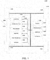
- FIG. 1 is a diagram of an example of a vehicle 1000 in which the aspects, features and elements disclosed herein may be implemented.
- the vehicle 1000 may include a chassis 1100, a powertrain 1200, a controller 1300, wheels 1400, or any other element or combination of elements of a vehicle.
- the vehicle 1000 is shown as including four wheels 1400 for simplicity, any other propulsion device or devices, such as a propeller or tread, may be used.
- the lines interconnecting elements, such as the powertrain 1200, the controller 1300 and the wheels 1400 indicate that information, such as data or control signals, power, such as electrical power or torque, or both information and power, may be communicated between the respective elements.
- the controller 1300 may receive power from the powertrain 1200 and may communicate with the powertrain 1200, the wheels 1400, or both, to control the vehicle 1000, which may include accelerating, decelerating, steering, or otherwise controlling the vehicle 1000.
- the powertrain 1200 may include a power source 1210, a transmission 1220, a steering unit 1230, an actuator 1240, or any other element or combination of elements of a powertrain, such as a suspension, a drive shaft, axles or an exhaust system. Although shown separately, the wheels 1400 may be included in the powertrain 1200.
- the power source 1210 may include an engine, a battery, or a combination thereof.
- the power source 1210 may be any device or combination of devices operative to provide energy, such as electrical energy, thermal energy, or kinetic energy.
- the power source 1210 may include an engine, such as an internal combustion engine, an electric motor, or a combination of an internal combustion engine and an electric motor, and may be operative to provide kinetic energy as a motive force to one or more of the wheels 1400.
- the power source 1210 may include a potential energy unit, such as one or more dry cell batteries, such as nickel-cadmium (NiCd), nickel-zinc (NiZn), nickel metal hydride (NiMH), lithium-ion (Li-ion); solar cells; fuel cells; or any other device capable of providing energy.
- a potential energy unit such as one or more dry cell batteries, such as nickel-cadmium (NiCd), nickel-zinc (NiZn), nickel metal hydride (NiMH), lithium-ion (Li-ion); solar cells; fuel cells; or any other device capable of providing energy.
- the transmission 1220 may receive energy, such as kinetic energy, from the power source 1210, and may transmit the energy to the wheels 1400 to provide a motive force.
- the transmission 1220 may be controlled by the control unit 1300, the actuator 1240, or both.
- the steering unit 1230 may be controlled by the control unit 1300, the actuator 1240, or both, and may control the wheels 1400 to steer the vehicle 1000.
- the vehicle actuator 1240 may receive signals from the controller 1300 and may actuate or control the power source 1210, the transmission 1220, the steering unit 1230, or any combination thereof to operate the vehicle 1000.
- the controller 1300 may include a location unit 1310, an electronic communication unit 1320, a processor 1330, a memory 1340, a user interface 1350, a sensor 1360, an electronic communication interface 1370, or any combination thereof. Although shown as a single unit, any one or more elements of the controller 1300 may be integrated into any number of separate physical units.
- the user interface 1350 and processor 1330 may be integrated in a first physical unit and the memory 1340 may be integrated in a second physical unit.
- the controller 1300 may include a power source, such as a battery.
- the location unit 1310, the electronic communication unit 1320, the processor 1330, the memory 1340, the user interface 1350, the sensor 1360, the electronic communication interface 1370, or any combination thereof, may be integrated in one or more electronic units, circuits or chips.
- the processor 1330 may include any device or combination of devices capable of manipulating or processing a signal or other information now-existing or hereafter developed, including optical processors, quantum processors, molecular processors, or a combination thereof.
- the processor 1330 may include one or more special purpose processors, one or more digital signal processors, one or more microprocessors, one or more controllers, one or more microcontrollers, one or more integrated circuits, one or more Application Specific Integrated Circuits, one or more Field Programmable Gate Array, one or more programmable logic arrays, one or more programmable logic controllers, one or more state machines, or any combination thereof.
- the processor 1330 may be operatively coupled with the location unit 1310, the memory 1340, the electronic communication interface 1370, the electronic communication unit 1320, the user interface 1350, the sensor 1360, the powertrain 1200, or any combination thereof.
- the processor may be operatively coupled with the memory 1340 via a communication bus 1380.
- the memory 1340 may include any tangible non-transitory computer-usable or computer-readable medium capable of, for example, containing, storing, communicating, or transporting machine-readable instructions, or any information associated therewith, for use by or in connection with the processor 1330.
- the memory 1340 may be, for example, one or more solid state drives, one or more memory cards, one or more removable media, one or more read only memories, one or more random access memories, one or more disks, including a hard disk, a floppy disk, an optical disk, a magnetic or optical card, or any type of non-transitory media suitable for storing electronic information, or any combination thereof.
- the communication interface 1370 may be a wireless antenna, as shown, a wired communication port, an optical communication port, or any other wired or wireless unit capable of interfacing with a wired or wireless electronic communication medium 1500.
- FIG. 1 shows the communication interface 1370 communicating via a single communication link, a communication interface 1370 may be configured to communicate via multiple communication links.
- the communication unit 1320 may be configured to transmit or receive signals via the wired or wireless medium 1500, such as via the communication interface 1370. Although not explicitly shown in FIG. 1 , the communication unit 1320 may be configured to transmit, receive, or both, via any wired or wireless communication medium, such as radio frequency (RF), ultra violet (UV), visible light, fiber optic, wire line, or a combination thereof. Although FIG. 1 shows a single communication unit 1320 and a single communication interface 1370, any number of communication units and any number of communication interfaces may be used.
- RF radio frequency
- UV ultra violet
- FIG. 1 shows a single communication unit 1320 and a single communication interface 1370, any number of communication units and any number of communication interfaces may be used.
- the location unit 1310 may determine geolocation information, such as longitude, latitude, elevation, direction of travel, or speed, of the vehicle 1000.
- the location unit may include a global positioning system (GPS) unit, such as a Wide Area Augmentation System (WAAS) enabled National Marine Electronics Association (NMEA) unit, a radio triangulation unit, or a combination thereof.
- GPS global positioning system
- WAAS Wide Area Augmentation System
- NMEA National Marine Electronics Association
- the location unit 1310 can be used to obtain information that represents, for example, a current heading of the vehicle 1000, a current position of the vehicle 1000 in two or three dimensions, a current angular orientation of the vehicle 1000, or a combination thereof.
- the user interface 1350 may include any unit capable of interfacing with a person, such as a virtual or physical keypad, a touchpad, a display, a touch display, a speaker, a microphone, a video camera, a sensor, a printer, or any combination thereof.
- the user interface 1350 may be operatively coupled with the processor 1330, as shown, or with any other element of the controller 1300.
- the user interface 1350 may include one or more physical units.
- the user interface 1350 may include an audio interface for performing audio communication with a person and/or a touch display for performing visual and touch-based communication with the person.
- the sensor 1360 often includes one or more sensors 1360, such as an array of sensors, which may be operable to provide information that may be used to control the vehicle 1000.
- the sensor 1360 may provide information regarding current operating characteristics of the vehicle.
- sensors 1360 can include, for example, a speed sensor, acceleration sensors, a steering angle sensor, traction-related sensors, braking-related sensors, or any sensor, or combination of sensors, that is operable to report information regarding some aspect of the current dynamic situation of the vehicle 1000.
- the sensors 1360 may include one or more sensors that are operable to obtain information regarding the physical environment surrounding the vehicle 1000.
- one or more sensors 1360 may detect road geometry and obstacles, such as fixed obstacles, vehicles and pedestrians.
- the sensors 1360 can be or include one or more video cameras, laser-sensing systems, infrared-sensing systems, acoustic-sensing systems, or any other suitable type of on-vehicle environmental sensing device, or combination of devices, now known or later developed.
- the sensors 1360 and the location unit 1310 may be combined.
- the vehicle 1000 may include a trajectory controller.
- the trajectory controller may be operable to obtain information describing a current state of the vehicle 1000 and a route planned for the vehicle 1000, and, based on this information, to determine and optimize a trajectory for the vehicle 1000.
- the trajectory controller may output signals operable to control the vehicle 1000 such that the vehicle 1000 follows the trajectory that is determined by the trajectory controller.
- the output of the trajectory controller can be an optimized trajectory that may be supplied to the powertrain 1200, the wheels 1400, or both.
- the optimized trajectory can be control inputs such as a set of steering angles, with each steering angle corresponding to a point in time or a position.
- the optimized trajectory can be one or more lanes, lines, curves, paths, or a combination thereof.
- the trajectory controller may be implemented, at least in part, using one or more elements of the controller 1300.
- One or more of the wheels 1400 may be a steered wheel, which may be pivoted to a steering angle under control of the steering unit 1230, a propelled wheel, which may be torqued to propel the vehicle 1000 under control of the transmission 1220, or a steered and propelled wheel that may steer and propel the vehicle 1000.
- the vehicle 1000 may include units, or elements not shown in FIG. 1 , such as an enclosure, a Bluetooth® module, a frequency modulated (FM) radio unit, a Near Field Communication (NFC) module, a liquid crystal display (LCD) display unit, an organic light-emitting diode (OLED) display unit, a speaker, or any combination thereof.
- a Bluetooth® module a frequency modulated (FM) radio unit
- NFC Near Field Communication
- LCD liquid crystal display
- OLED organic light-emitting diode
- speaker or any combination thereof.
- FIG. 2 is a diagram of an example of a portion of a vehicle transportation and communication system in which the aspects, features and elements disclosed herein may be implemented.
- the vehicle transportation and communication system 2000 may include at least two vehicles 2100/2110, each of which may be configured similarly to the vehicle 1000 shown in FIG. 1 , which travel via one or more portions of one or more vehicle transportation networks 2200, and may communicate via one or more electronic communication networks 2300.
- a vehicle may traverse an area that is not expressly or completely included in a vehicle transportation network, such as an off-road area.
- the electronic communication network 2300 may be, for example, a multiple access system and may provide for communication, such as voice communication, data communication, video communication, messaging communication, or a combination thereof, between each vehicle 2100/2110 and one or more communicating devices 2400.
- a vehicle 2100/2110 may receive information, such as information representing the vehicle transportation network 2200, from a communicating device 2400 via the network 2300.
- the electronic communication network 2300 can be used in vehicle-to-vehicle communication of the basic safety message containing location and trajectory information of the vehicle 2100.
- Each vehicle 2100/2110 may also communicate this information directly to one or more other vehicles as discussed in more detail below.
- a vehicle 2100/2110 may communicate via a wired communication link (not shown), a wireless communication link 2310/2320/2370, or a combination of any number of wired or wireless communication links.
- a vehicle 2100/2110 may communicate via a terrestrial wireless communication link 2310, via a non-terrestrial wireless communication link 2320, or via a combination thereof.
- a terrestrial wireless communication link 2310 may include an Ethernet link, a serial link, a Bluetooth link, an infrared (IR) link, an ultraviolet (UV) link, or any link capable of providing for electronic communication.
- a vehicle 2100/2110 may communicate with another vehicle 2100/2110.
- a host, or subject, vehicle (HV) 2100 may receive one or more automated inter-vehicle messages, such as the basic safety message, from a remote, or target, vehicle (RV) 2110, via a direct communication link 2370, or via the network 2300.
- the remote vehicle 2110 may broadcast the message to host vehicles within a defined broadcast range, such as 300 meters.
- the host vehicle 2100 may receive a message via a third party, such as a signal repeater (not shown) or another remote vehicle (not shown).
- a vehicle 2100/2110 may transmit one or more automated inter-vehicle messages periodically based on a defined interval, such as 100 milliseconds.
- Automated inter-vehicle messages may include vehicle identification information, spatial state information, such as longitude, latitude and/or elevation information, geospatial location accuracy information, kinematic state information, such as vehicle acceleration information, yaw rate information, speed information, vehicle heading information, braking system status information, throttle information, steering wheel angle information, or vehicle routing information, or vehicle operating state information, such as vehicle size information, headlight state information, turn signal information, wiper status information, transmission information, or any other information, or combination of information, relevant to the transmitting vehicle state.
- transmission state information may indicate whether the transmitting vehicle is in a neutral state, a parked state, a forward state or a reverse state.
- the communication unit 1320 can receive SONAR, RADAR, and/or LIDAR signals from which vehicle position, speed, acceleration and instantaneous heading can be calculated.
- the vehicle 2100 may communicate with the communications network 2300 via an access point 2330.
- the access point 2330 which may include a computing device, may be configured to communicate with a vehicle 2100, with a communication network 2300, with one or more communication devices 2400, or with a combination thereof via wired or wireless communication links 2310/2340.
- an access point 2330 may be a base station, a base transceiver station (BTS), a Node-B, an enhanced Node-B (eNode-B), a Home Node-B (HNode-B), a wireless router, a wired router, a hub, a relay, a switch, or any similar wired or wireless device.
- BTS base transceiver station
- eNode-B enhanced Node-B
- HNode-B Home Node-B
- a wireless router a wired router, a hub, a relay, a switch, or any similar wired or wireless device.
- an access point may include any number of interconnected elements
- the vehicle 2100 may communicate with the communications network 2300 via a satellite 2350, or other non-terrestrial communication device.
- the satellite 2350 which may include a computing device, may be configured to communicate with the vehicle 2100, with the communication network 2300, with one or more communication devices 2400, or with a combination thereof via one or more communication links 2320/2360.
- a satellite may include any number of interconnected elements.
- the vehicle 2110 may similarly communicate with the communications network 2300 via the access point 2330 and/or the satellite 2350.
- An electronic communication network 2300 may be any type of network configured to provide for voice, data, or any other type of electronic communication.
- the electronic communication network 2300 may include a local area network (LAN), a wide area network (WAN), a virtual private network (VPN), a mobile or cellular telephone network, the Internet, or any other electronic communication system.
- the electronic communication network 2300 may use a communication protocol, such as the transmission control protocol (TCP), the user datagram protocol (UDP), the internet protocol (IP), the real-time transport protocol (RTP) the Hyper Text Transport Protocol (HTTP), or a combination thereof.
- TCP transmission control protocol
- UDP user datagram protocol
- IP internet protocol
- RTP real-time transport protocol
- HTTP Hyper Text Transport Protocol
- a vehicle 2100 may identify a portion or condition of the vehicle transportation network 2200.
- the vehicle may include one or more on-vehicle sensors 2150, such as sensor 1360 shown in FIG. 1 , which may include a speed sensor, a wheel speed sensor, a camera, a gyroscope, an optical sensor, a laser sensor, a radar sensor, a sonic sensor, or any other sensor or device or combination thereof capable of determining or identifying a portion or condition of the vehicle transportation network 2200.
- a vehicle 2100 may traverse a portion or portions of one or more vehicle transportation networks 2200 using information communicated via the network 2300, such as information representing the vehicle transportation network 2200, information identified by one or more on-vehicle sensors 2150, or a combination thereof.
- FIG. 2 shows one vehicle transportation network 2200, one electronic communication network 2300, and one communication device 2400, any number of networks or communication devices may be used.
- the vehicle transportation and communication system 2000 may include devices, units or elements not shown in FIG. 2 .
- each vehicle 2100/2110 is shown as a single unit, a vehicle may include any number of interconnected elements.
- each vehicle 2100/2110 may communicate with the communication device 2400 via a direct communication link, such as a Bluetooth communication link.
- FIG. 3 is a flow chart of a method of generating projected vehicle information for use in traversing a vehicle transportation network according to the teachings herein.
- the method may be implemented in a vehicle, such as the vehicle 1000 shown in FIG. 1 or the vehicles 2100/2110 shown in FIG. 2 .
- the method may be implemented in whole or in part external of vehicles, such as within one or more processors of communication device 2400, with transmission of relevant information, such as a remote vehicle trajectory or a generated route, to one or more vehicles.
- the method includes receiving remote vehicle information at 3000, identifying vehicle transportation network information at 3010, generating an initial probability value for one or more lanes within the vehicle transportation network information at 3020, generating deviations in the vehicle along the lanes for subsequent time points at 3030, updating the probability values for the lanes at 3040, generating the remote vehicle trajectory over time at 3050, and traversing the vehicle transportation network using the remote vehicle trajectory as input at 3060.
- Host vehicle receives remote vehicle information while traversing a portion of a vehicle transportation network at 3000.
- Remote vehicle information received by a host vehicle at 3000 includes remote vehicle spatial state information and may include remote vehicle kinematic state information for the remote vehicle, or data from which this information may be generated.
- the remote vehicle spatial state information may include, for example, geospatial coordinates for the remote vehicle. These coordinates may be GPS coordinates for a latitude and a longitude of the remote vehicle in some embodiments.
- the remote vehicle kinematic state information may include a speed, acceleration, heading angle, etc., or information from which this information may be determined.
- remote vehicle spatial state information may be received by importing the information from one or more datasets.
- the information is imported from signals sent through the wireless electronic communication medium 1500 from the location unit 1310 of FIG. 1 .
- the information may be associated with records from a single remote vehicle or multiple remote vehicles. Each record in a dataset may be associated with a vehicle identifier, and individual remote vehicles may be uniquely identified based on the vehicle identifiers.
- the records may also include date and time stamps, and may be retrieved periodically or on an as-needed basis, such as when the vehicle transportation network upon which a vehicle is traveling changes.
- remote vehicle spatial state information may be received from a location of an infrastructure device in the vehicle transportation network.
- infrastructure devices may include smart devices such as a traffic light, a road sensor, a road camera, or any other non-vehicle device associated with the vehicle transportation network and capable of detecting a vehicle.
- remote vehicle spatial state information may be received from a portable device while it is associated with a vehicle.
- a portable device such as a smartphone, carried by a passenger of the vehicle may include geographic location information, such as GPS or assisted GPS (AGPS) information and may include information associating the passenger with the vehicle.
- AGPS assisted GPS
- vehicle spatial state information is not limited to any particular technique provided that the technique can associate the vehicle spatial state information with at least one other piece of information such as time and a particular remote vehicle.
- the technique can associate the vehicle spatial state information with at least one other piece of information such as time and a particular remote vehicle.
- SONAR, RADAR, and/or LIDAR mounted on vehicles or infrastructure devices may provide input that can be used to calculate or otherwise generate vehicle spatial state information at 3000.
- Similar techniques may be used to receive remote vehicle kinematic state information. For example, when a remote vehicle remains at the same location between two measurements, it can be determined that the remote vehicle is not moving. In contrast, when the remote vehicle spatial state information is different for a remote vehicle between two measurements, the information and the amount of time between the two measurements may be used to generate a speed of the remote vehicle.
- remote vehicle information received by a host vehicle at 3000 may be in the form of the automated inter-vehicle messages described above.
- the information may be received in whole or in part through dedicated short-range communications (DSRC) in vehicle-to-vehicle (V2V) and vehicle-to-infrastructure (V21) short-range wireless communications.
- DSRC dedicated short-range communications
- V2V vehicle-to-vehicle
- V21 vehicle-to-infrastructure
- the remote vehicle information may be stored in memory of the host vehicle or elsewhere for subsequent processing and may be stored with a time stamp.
- host vehicle information may be received and stored using similar techniques.
- raw observations e.g., location and velocity
- vehicle transportation network information that represents a portion of the vehicle transportation network is identified.
- the identification may be based on the remote vehicle spatial state information, and the remote vehicle is located within the remote vehicle transportation network information.
- a vehicle transportation network may include one or more unnavigable areas, such as a building, one or more partially navigable areas, such as a parking area, one or more navigable areas, such as roads, or a combination thereof.
- the vehicle transportation network may include one or more interchanges between one or more navigable, or partially navigable, areas.
- a portion of the vehicle transportation network, such as a road may include one or more lanes, and may be associated with one or more directions of travel. Lanes can be marked or unmarked.
- a vehicle transportation network may be represented as vehicle transportation network information.
- vehicle transportation network information may be expressed as a hierarchy of elements, such as markup language elements, which may be stored in a database or file.
- the figures herein depict vehicle transportation network information representing portions of a vehicle transportation network as diagrams or maps; however, vehicle transportation network information may be expressed in any computer-usable form capable of representing a vehicle transportation network, or a portion thereof.
- the vehicle transportation network information may include vehicle transportation network control information, such as direction of travel information, speed limit information, toll information, grade information, such as inclination or angle information, surface material information, aesthetic information, or a combination thereof.
- the vehicle transportation network may be associated with, or may include, a pedestrian transportation network such as a pedestrian walkway or a sidewalk or a bicycle transportation network such as one or more bicycle lanes.
- the pedestrian transportation network may correspond with a non-navigable/unnavigable area or a partially navigable area of a vehicle transportation network.
- a bicycle transportation network may correspond with a non-navigable/unnavigable area or a partially navigable area of a vehicle transportation network.
- the description here uses a motor vehicle, the teachings are applicable to other vehicles that travel along a defined lane within the vehicle transportation network such as a motorized bicycle or motorcycle.
- FIG. 4A is a diagram illustrating a remote vehicle within a portion of a vehicle transportation network at an initial time point for use in generating projected vehicle information in accordance with this disclosure.
- vehicle transportation network information that represents a portion of the vehicle transportation network may be identified based on the remote vehicle spatial state information.
- the portion may include, in addition to a current lane in which the remote vehicle is traveling, successor and predecessor lanes to the current lane and any adjacent lanes (also referred to as sibling lanes) that are near the remote vehicle.
- the portion could be a defined distance or could be variable based on the traveling speed of the remote vehicle. For example, the portion could be identified based on a radius defined by how far the remote vehicle could travel at its current speed.
- FIG. 4A shows only two lanes or lanes 4100, 4200 extending from a common lane 4000, each having no sibling lanes.
- a centerline 4210 of lane 4200 is also shown.
- the remote vehicle 4300 is located within the portion of the vehicle transportation network information at an initial time point, which location is represented as point A.
- the location on a lane may be referred to as the pose of the remote vehicle.
- the remote vehicle spatial state information and vehicle transportation network information should be identified in the same coordinate system. To this end, the coordinates of the remote vehicle spatial state information are transformed to a common coordinate system.
- the common coordinate system may be, in some embodiments, the Universal Transverse Mercator (UTM) coordinate system such that the input points are transformed to UTM coordinates in each UTM zone.
- UTM Universal Transverse Mercator
- the vehicle spatial state information identified from the datasets may be transformed to UTM coordinates according to known conversion formulas.
- Other coordinate systems are possible as long as the selected system is used consistently.
- the method proceeds to 3020 after identifying the vehicle transportation network information at 3010.
- at 3020 at least one initial probability value is generated based on a comparison of the remote vehicle spatial state information and the vehicle transportation network information at an initial time point.
- Each initial probability value indicates likelihood that the remote vehicle is following a single lane within the vehicle transportation network information. It can also be considered as the probability that the vehicle is following the orientation of a specific lane or as the driving intention state.
- the driving intention state can be to go straight, turn left, or turn right.
- the driving intention state can be to go straight, make a left lane change, or make a right lane change.
- the remote vehicle 4300 is at the location identified by point A at the initial time point (also call the first calculation point or first point).
- the first calculation point can be any point within a series of received data for the remote vehicle. It can be located at the first point at which a unique id associated with the remote vehicle is detected or assigned, for example.
- the initial probability value at the first calculation point can be generated in any number of ways. As one example, when the remote vehicle is on a lane or lane having no sibling lanes, the initial probability value is 1 as the likelihood of going straight is 100%. When the remote vehicle is at an intersection, the probabilities may be inferred based on the potential options available to the vehicle at the first calculation point. In FIG.
- the likelihoods may vary based on other variables.
- that signal often includes other data.
- a turn signal may be used to more heavily weigh one driving intention state over another. In other words, there may be situations in which the remote vehicle is in a position or other circumstances occur such that the probabilities are not evenly distributed among the possible options.
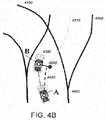
- FIG. 4B is a diagram illustrating the remote vehicle 4300 within the portion of the vehicle transportation network at a subsequent time point to the time point of FIG. 4A
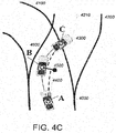
- FIG. 4C is a diagram illustrating the remote vehicle 4300 within the portion of the vehicle transportation network at a subsequent time point to the time point of FIG. 4B . That is, the remote vehicle 4300 continues to travel after it is located at first point A in FIG. 4A , and is identified by the remote vehicle spatial state information at a second point B in FIG. 4B and then at a third point C in FIG. 4C .
- the remote vehicle 4300 travels further away from the centerline 4210 of the lane 4200 when progressing from the first point A to the second point B and then travels closer to the centerline 4210 of the lane 4200 when progressing from the second point B to the third point C. Intuitively, then, the probability that the remote vehicle 4200 will follow the lane 4200 decreases at the second point B and increases at the third point C.
- a deviation of the remote vehicle 4200 between adjacent values for the remote vehicle spatial state information relative to the vehicle transportation network information can be generated and used to generate a new probability over time.
- a deviation may be generated by locating a dashed line 4400 that extends in parallel with the centerline 4210 of the lane 4200 from a Euclidean line 4500 between the second point B and the centerline 4210 of the lane 4200 to the first point A.
- the difference between the second point B and the point where the first point A is projected onto the Euclidian line 4500 by the dashed line 4400 represents the deviation in the trajectory of the remote vehicle 4300 from the first point A to the second point B.
- next deviation may be generated by locating a dashed line 4600 that extends in parallel with the centerline 4210 of the lane 4200 from the third point C to the Euclidean line 4500 between the second point B and the centerline 4210 of the lane 4200.
- the difference between the second point B and the point where the third point C is projected onto the Euclidean line 4500 by the dashed line 4600 represents the deviation in the trajectory of the remote vehicle 4300 from the second point B to the third point C.
- a Euclidean line could extend from the centerline 4210 through the third point C (similar to line 4500 through the second point B), and a parallel line could project forward from the second point B to that Euclidean line.
- the difference between the third point C and the point where the second point B is projected onto the Euclidean line by the parallel line also represents the deviation in the trajectory of the remote vehicle 4300 from the second point B to the third point C.
- These deviations may also be referred to as relative deviations.
- a new probability value based on the relative deviation between the second point B and the third point C may be a probability of deviation from the previous point.
- a value of 0.5 is used.
- the new probability value is used to divide the likelihood at the previous point because the remote vehicle 4300 is moving closer to the centerline 4210 so the updated likelihood must increase.
- FIGS. 4A-4C illustrates the use of the relative deviation in updating the likelihood that the remote vehicle is following a particular lane.
- Several functions may be used.
- the lateral distribution of points along a centerline, such as the centerline 4210 is Gaussian. Therefore, the cumulative distribution function of Gaussian is used to relate deviations to probabilities.
- ⁇ standard deviation
- FIG. 5 illustrates the calculation of a deviation between adjacent values for remote vehicle spatial state information relative to vehicle transportation network information.
- FIG. 5 uses positive values for the deviation to the left and negative values for deviation to the right as an example-which side is positive does not affect the technique.
- a single lane 5000 is shown that has a left lane boundary 5010, a right lane boundary 5020 and a centerline 5030.
- the centerline 5030 is most often not labeled or shown in conventional map data and may be defined for the purposes herein as the midpoint between the left lane boundary 5010 and the right lane boundary 5020.
- a solid line 5100 indicates the trajectory of the vehicle along the lane 5000.
- the vehicle was observed at points A, B, C, D, E, F over time (i.e., at the white dots).
- the black dots mark the point on centerline 5030 that is closest to the location of the vehicle at the instant of observation. As mentioned briefly with respect to FIGS. 4B and 4C , this defines a Euclidean line.
- the Euclidean distance between respective white and black dots is the deviation of the vehicle from the centerline 5030 at the instant of observation. However, it is the deviation between points that is of interest.
- Point A is the point at which the initial probability value for the lane 5000 is generated at 3020.
- the probability of going straight is 1.0 as only one lane is shown.
- each deviation may be calculated for a new point by extending a Euclidean line through the new point and the centerline, extending a line from the previous point to the Euclidean line, and calculating a difference between the new point and point where the previous point intersects the Euclidean line.
- the deviations are calculated in a like manner as described with respect to FIGS. 4B and 4C .
- the deviation of the vehicle from the centerline 5030 at point A 0.1
- the deviation of the vehicle from the centerline 5030 at point B 0.16.
- the probability values are updated for the lane 5000 at 3040. In some embodiments, they are updated using the probability function f ( x ) and the generated deviations. Using the values in FIG. 5 , the going straight probability (i.e., the likelihood of following lane 5000) can be calculated according to the following general rules.
- Point F represents a different situation from the analysis of the prior points as the vehicle crosses the centerline 5030.
- the vehicle first moves toward the centerline 5030 of the lane 5000 and then moves away from the centerline 5030 of the lane 5000.
- the line from point E to point F may be divided into two parts-one from point E to the centerline 5030 and the other from the centerline 5030 to point F.
- the probability of a left lane change that is, a change into the left lane
- p LLC 1 ⁇ p GS
- the vehicle is in an intersection.
- the probability values depend upon the number of lane options the vehicle has.
- p ( GS ) is calculated using a respective centerline. Because the probability or likelihood of following each lane is calculated separately, the combined values would result in a likelihood of over 100%. Accordingly, the probabilities for each option are normalized with respect to the other options so as not to exceed a probability of 1.0, for example.
- processing advances to 3050 to generate the a remote vehicle trajectory for up to N seconds.
- the trajectory is generated for up to 4 seconds.
- Other values for N may be specified by a user or operator.
- FIG. 6 is a diagram illustrating generation of the trajectory of the remote vehicle over time based on the weighted average of trajectories predicted based on velocity and map curvature.
- FIG. 6 shows one lane 6100 and the trajectory for the vehicle 6000 when it follows the lane 6100, but calculations would be similar for other driving intentions (left turn, right turn, lane change, etc.).
- the remote vehicle 6000 was most recently located at the point shown in FIG. 6 traveling in the lane 6100 from preceding lane 6200.
- the centerline 6150 of lane 6100 is also shown in FIG. 6 .
- vehicle velocity is a vector having a heading and a magnitude.
- the predicted trajectory of the vehicle 6000 based on the vehicle velocity is shown extending over time by the arrow 6300.
- the vehicle velocity may be obtained from, for example, the remote vehicle kinetic state information optionally received in the process of FIG. 3 at 3000 or may be calculated, in whole or in part, from other information received at 3000. Knowing the velocity and the position of the remote vehicle 6000, the trajectory up to K seconds can be predicted.
- FIG. 6 also illustrates a predicted trajectory that follows the curvature of the lane 6100.
- This predicted trajectory for up to K seconds shown by the arrow 6400 follows the centerline 6150 of lane 6100 using the speed of the vehicle 6000.
- the vehicle speed may be obtained from, for example, the remote vehicle kinetic state information optionally received in the process of FIG. 3 at 3000 or may be calculated, in whole or in part, from other information received at 3000.
- the arrow 6500 represents a trajectory of the vehicle 6000 that is a weighted average of the trajectory prediction based on the current velocity represented by the arrow 6300 and the trajectory prediction based on the map curvature represented by the arrow 6400.
- FIG. 7 is a diagram illustrating the weighting function that may be used for generating the trajectory of FIG. 6 .
- the numbers and lines are arbitrary to illustrate the principles involved and do not represent values within FIG. 6 .
- the numbers represent the weight given to each trajectory prediction over time.
- the weighting function is based on the assumption that, over time, the vehicle will move toward the centerline of the predicted lane as shown by the arrow 7000. That is, for example, the velocity predictions of trajectory are to the left in FIG. 7 and the map curvature predictions of trajectory are to the right in FIG. 7 .
- the maximum weight (such as 1.0) is given to the velocity prediction of the trajectory and a minimal weight (such as 0) is given to the map curvature prediction of the trajectory.
- the weighting between the two predictions change such that the maximum weight is given to the map curvature prediction of the trajectory and the minimal weight is given to the velocity prediction of the trajectory at a future point 7200 at K seconds for example.
- weighting of the two predictions is performed using a cosine function.
- the weight of the map predictions may follow the following equation: 0.5 ⁇ 0.5 ⁇ cos 2 ⁇ / 2 ⁇ InterpolationTimeLength ⁇ t ; and the weight of the velocity predictions may follow the equation: 1 ⁇ 0.5 ⁇ 0.5 ⁇ cos 2 ⁇ / 2 ⁇ InterpolationTimeLength ⁇ t .
- the variable Interpolation Time Length is equal to the length of time that the weight of map prediction changes from 0.0 to 1.0 or the weight of the velocity prediction changes from 1.0 to 0.0. This variable may be specified by a user.
- the weighted trajectory at point 7300 would be equal to: 0.345 ⁇ T M + 0.655 ⁇ T V .
- the trajectory may be calculated for up to K seconds in the future.
- the driving intention is an input into this process as seen in FIG. 8 . More specifically, as the remote vehicle traverses the vehicle transportation network, it approaches changes in the vehicle transportation network information (e.g., lane changes) that must be taken into account in the generation of the remote vehicle trajectory.
- the remote vehicle is at a current point 8000 on a single lane 8050 where the current driving intention can only be to go straight.
- An example of the trajectory for the remote vehicle is labeled 8100.
- the driving intention may be go straight or right turn due to the presence of lanes 8300 and 8400.
- the vehicle pose i.e., its position within the vehicle transportation network information
- velocity are recalculated at point 8200 so as to generate the next segment of the trajectory, such as the trajectory 8500 for the next driving intention of right turn, for another 2 seconds.
- the trajectory is generated as described above with respect to FIGS. 6 and 7 , and it is generated for each driving intention (e.g., lane).
- the remote vehicle trajectory may be used to assist a host vehicle in traversing the vehicle transportation network.
- the host vehicle 9000 and a remote vehicle 9100 are traveling within a portion of the vehicle transportation network, here an intersection 9300.
- the vehicle transportation network information includes lanes 1-8, and four stop signs, each represented by lines 9400.
- the host vehicle 9000 is located in lane 2, and will continue to lane 5 as shown by the arrow extending from the host vehicle 9000.
- the remote vehicle 9100 is lane 8, and can go straight or turn left or turn right as shown by the arrows extending from the remote vehicle 9100.
- the remote vehicle 9100 arrives at the stop sign of lane 8 before the host vehicle 9000 arrives at the stop sign of lane 2.
- a lane change in the intersection 9300 is not included as a possible driving intention.
- the host vehicle 9000 may make a decision regarding traversal of the intersection 9300, for example, based on the remote vehicle trajectory for lane and the likelihood that the remote vehicle 9100 will follow one driving intention or the other (i.e., go straight or left turn or right turn). For example, the host vehicle 9000 may decide to wait at the stop sign in lane 2 to let the remote vehicle 9100 pass the intersection 9300 if it is more likely than not that the remote vehicle 9100 will continue to lane 3, thus blocking the path of the host vehicle 9000 (e.g., the driving intention of go straight has a higher likelihood or probability than the driving intention of turn left and turn right). In contrast, the host vehicle 9000 might choose to make a brief stop and continue to go straight if it is more likely than not that the remote vehicle 9100 will turn right into lane l as the remote vehicle 9100 will not block the host vehicle 9000.
- the host vehicle 9000 might choose to make a brief stop and continue to go straight if it is more likely than not that the remote vehicle 9100 will turn right into lane
- the host vehicle 9000 may use the driving intentions and projected trajectories in any number of ways. For example, when both vehicles are traveling in the same lane on a straight road, the host vehicle 9000 may use the projected trajectory to determine if and when it will reach the remote vehicle 9100 to pass it. In another example, the remote vehicle 9100 may travel in a lane left of the host vehicle 9000 on a straight road. The host vehicle 9000 can then use the projected trajectory to determine if and when it should brake if the remote vehicle 9100 shows an intention of changing to the lane that the host vehicle 9000 is traveling in.
- the host vehicle 9000 may also indirectly use the information generated for the remote vehicle 9100 by, for example, a network infrastructure device, such as a traffic controller at an intersection, receiving or generating the (e.g., remote and host) vehicle information and directing the intersection flow through traffic lights or otherwise using the trajectories and likelihoods.
- a network infrastructure device such as a traffic controller at an intersection
- receiving or generating the (e.g., remote and host) vehicle information and directing the intersection flow through traffic lights or otherwise using the trajectories and likelihoods.
- Traversing the vehicle transportation network could involve actions such as issuing alarms to the driver of the host vehicle or taking corrective actions such as issuing braking instructions to a braking system of the host vehicle. Other corrective actions may be taken while the host vehicle is traversing the vehicle transportation network at 3060.
- the method as described by example in FIG. 3 can be repeated periodically or on demand while the host vehicle is traveling along the vehicle transportation network. It can also be repeated in whole or in part when approaching changes in the lane configuration within the vehicle transportation network information.
- the disclosure describes a single remote vehicle as the tracked object, other motorized vehicles that maintain positions within a defined lane may also be tracked. Further, more than one remote vehicle may be tracked over time.
- the above includes at most three lanes diverging from the same predecessor lane at an intersection-a straight lane, a left turn lane and a right turn lane. Further complexity is introduced into the calculations when additional lanes are introduced or when lane changes within an intersection can occur.
Landscapes
- General Physics & Mathematics (AREA)
- Physics & Mathematics (AREA)
- Engineering & Computer Science (AREA)
- Chemical & Material Sciences (AREA)
- Analytical Chemistry (AREA)
- Atmospheric Sciences (AREA)
- Life Sciences & Earth Sciences (AREA)
- Automation & Control Theory (AREA)
- Transportation (AREA)
- Mechanical Engineering (AREA)
- Remote Sensing (AREA)
- Radar, Positioning & Navigation (AREA)
- Computer Networks & Wireless Communication (AREA)
- Human Computer Interaction (AREA)
- Traffic Control Systems (AREA)
- Aviation & Aerospace Engineering (AREA)
Applications Claiming Priority (2)
| Application Number | Priority Date | Filing Date | Title |
|---|---|---|---|
| US14/954,083 US10152882B2 (en) | 2015-11-30 | Host vehicle operation using remote vehicle intention prediction | |
| PCT/JP2016/085157 WO2017094656A1 (ja) | 2015-11-30 | 2016-11-28 | 車両道路網の走行に用いられる予測車両情報の生成方法及び装置 |
Publications (3)
| Publication Number | Publication Date |
|---|---|
| EP3385930A1 true EP3385930A1 (de) | 2018-10-10 |
| EP3385930A4 EP3385930A4 (de) | 2019-01-02 |
| EP3385930B1 EP3385930B1 (de) | 2020-03-04 |
Family
ID=58777686
Family Applications (1)
| Application Number | Title | Priority Date | Filing Date |
|---|---|---|---|
| EP16870593.7A Active EP3385930B1 (de) | 2015-11-30 | 2016-11-28 | Verfahren und vorrichtung zur erzeugung von prognostizierten fahrzeuginformationen für fahrten auf dem fahrzeugstrassennetz |
Country Status (10)
| Country | Link |
|---|---|
| US (1) | US10152882B2 (de) |
| EP (1) | EP3385930B1 (de) |
| JP (1) | JP6540826B2 (de) |
| KR (1) | KR101970931B1 (de) |
| CN (1) | CN108292475B (de) |
| BR (1) | BR112018010601A2 (de) |
| CA (1) | CA3006546A1 (de) |
| MX (1) | MX368090B (de) |
| RU (1) | RU2714056C2 (de) |
| WO (1) | WO2017094656A1 (de) |
Cited By (1)
| Publication number | Priority date | Publication date | Assignee | Title |
|---|---|---|---|---|
| CN114056347A (zh) * | 2020-07-31 | 2022-02-18 | 华为技术有限公司 | 车辆运动状态识别方法及装置 |
Families Citing this family (38)
| Publication number | Priority date | Publication date | Assignee | Title |
|---|---|---|---|---|
| DE102015015944A1 (de) * | 2015-12-08 | 2017-06-08 | Audi Ag | Verfahren zur Unterstützung eines Fahrers eines Kraftfahrzeugs hinsichtlich bevorstehender Überholmanöver und Kraftfahrzeug |
| US10486707B2 (en) * | 2016-01-06 | 2019-11-26 | GM Global Technology Operations LLC | Prediction of driver intent at intersection |
| US11640168B2 (en) * | 2016-08-31 | 2023-05-02 | Faraday & Future Inc. | System and method for controlling a driving system |
| CN108082185B (zh) * | 2017-03-30 | 2021-01-01 | 长城汽车股份有限公司 | 一种车辆的行驶控制方法、装置和车辆 |
| JP6717778B2 (ja) * | 2017-05-15 | 2020-07-08 | トヨタ自動車株式会社 | 道路リンク情報更新装置及び車両制御システム |
| CN108932462B (zh) * | 2017-05-27 | 2021-07-16 | 华为技术有限公司 | 驾驶意图确定方法及装置 |
| KR20190035159A (ko) * | 2017-09-26 | 2019-04-03 | 삼성전자주식회사 | 차량 움직임 예측 방법 및 장치 |
| US10745010B2 (en) * | 2017-12-21 | 2020-08-18 | International Business Machines Corporation | Detecting anomalous vehicle behavior through automatic voting |
| EP3514494A1 (de) * | 2018-01-19 | 2019-07-24 | Zenuity AB | Erstellung und aktualisierung einer verhaltensschicht einer mehrschichtigen hochdefinierten digitalen karte eines strassennetzes |
| EP3762926A4 (de) | 2018-01-31 | 2021-06-23 | Nissan North America, Inc. | Computing-rahmen zur batch-routenführung von autonomen fahrzeugen |
| US10994748B2 (en) | 2018-02-28 | 2021-05-04 | Nissan North America, Inc. | Transportation network infrastructure for autonomous vehicle decision making |
| US11378956B2 (en) * | 2018-04-03 | 2022-07-05 | Baidu Usa Llc | Perception and planning collaboration framework for autonomous driving |
| US10745011B2 (en) | 2018-05-31 | 2020-08-18 | Nissan North America, Inc. | Predicting yield behaviors |
| JP7140849B2 (ja) * | 2018-05-31 | 2022-09-21 | ニッサン ノース アメリカ,インク | 確率的オブジェクト追跡及び予測フレームワーク |
| EP3802254B1 (de) | 2018-05-31 | 2024-07-10 | Nissan North America, Inc. | Trajektorienplanung |
| US10564643B2 (en) | 2018-05-31 | 2020-02-18 | Nissan North America, Inc. | Time-warping for autonomous driving simulation |
| US10569773B2 (en) | 2018-05-31 | 2020-02-25 | Nissan North America, Inc. | Predicting behaviors of oncoming vehicles |
| EP3640679B1 (de) * | 2018-10-15 | 2023-06-07 | Zenuity AB | Verfahren zur zuweisung eines ego-fahrzeugs zu einer fahrspur |
| DK201970148A1 (en) * | 2018-12-10 | 2020-07-06 | Aptiv Tech Ltd | Motion graph construction and lane level route planning |
| US12192947B2 (en) * | 2019-02-19 | 2025-01-07 | Qualcomm Incorporated | Systems and methods for positioning with channel measurements |
| WO2020191711A1 (en) * | 2019-03-28 | 2020-10-01 | Baidu.Com Times Technology (Beijing) Co., Ltd. | A camera-based low-cost lateral position calibration method for level-3 autonomous vehicles |
| US11934191B2 (en) * | 2019-07-05 | 2024-03-19 | Huawei Technologies Co., Ltd. | Method and system for predictive control of vehicle using digital images |
| CN112242069B (zh) * | 2019-07-17 | 2021-10-01 | 华为技术有限公司 | 一种确定车速的方法和装置 |
| WO2021174445A1 (zh) * | 2020-03-04 | 2021-09-10 | 华为技术有限公司 | 预测车辆驶出口的方法和装置 |
| CN112133089B (zh) * | 2020-07-21 | 2021-11-19 | 西安交通大学 | 一种基于周围环境与行为意图的车辆轨迹预测方法、系统及装置 |
| US11688179B2 (en) * | 2020-09-03 | 2023-06-27 | Pony Ai Inc. | Inferring intent using computer vision |
| CN112687121A (zh) * | 2020-12-21 | 2021-04-20 | 苏州挚途科技有限公司 | 行驶轨迹的预测方法、装置及自动驾驶车辆 |
| CN113129603B (zh) * | 2021-03-26 | 2022-06-17 | 深圳市跨越新科技有限公司 | 平行道路超速判定方法、装置、终端及存储介质 |
| CN113324555B (zh) * | 2021-05-31 | 2024-05-03 | 阿波罗智联(北京)科技有限公司 | 一种车辆导航路径的生成方法、装置及电子设备 |
| US12017686B1 (en) * | 2021-08-11 | 2024-06-25 | Waymo Llc | Assessing surprise for autonomous vehicles |
| JP7609102B2 (ja) * | 2022-03-15 | 2025-01-07 | トヨタ自動車株式会社 | レーンネットワーク生成装置、レーンネットワーク生成方法及びレーンネットワーク生成用コンピュータプログラム |
| US12340342B2 (en) | 2022-10-11 | 2025-06-24 | Pitt-Ohio Express, Llc | System and method for tracing a transport |
| US12298787B1 (en) * | 2023-02-24 | 2025-05-13 | John Fazio | Directing multiple targets without interference |
| TWI845208B (zh) | 2023-03-14 | 2024-06-11 | 財團法人工業技術研究院 | 提前預知之抗暈眩補償方法與系統 |
| US12503107B2 (en) * | 2023-07-05 | 2025-12-23 | Ford Global Technologies, Llc | Interaction between host vehicle and target vehicle |
| KR102907632B1 (ko) | 2023-09-25 | 2026-01-05 | 엠투클라우드 주식회사 | 물류 IoT 기기들, 기지국 및 서버 간의 통신 제어 장치 및 방법 |
| US20250313207A1 (en) * | 2024-04-05 | 2025-10-09 | Toyota Motor Engineering & Manufacturing North America, Inc. | Lane selection using connected vehicle data including lane connectivity and input uncertainty information |
| CN120902753B (zh) * | 2025-10-11 | 2026-01-27 | 赛力斯汽车有限公司 | 一种车辆轨迹预测方法、系统、设备及存储介质 |
Family Cites Families (31)
| Publication number | Priority date | Publication date | Assignee | Title |
|---|---|---|---|---|
| US7629899B2 (en) * | 1997-10-22 | 2009-12-08 | Intelligent Technologies International, Inc. | Vehicular communication arrangement and method |
| US7796081B2 (en) * | 1997-10-22 | 2010-09-14 | Intelligent Technologies International, Inc. | Combined imaging and distance monitoring for vehicular applications |
| US6581005B2 (en) * | 2000-11-30 | 2003-06-17 | Nissan Motor Co., Ltd. | Vehicle position calculation apparatus and method |
| US6882287B2 (en) * | 2001-07-31 | 2005-04-19 | Donnelly Corporation | Automotive lane change aid |
| US7102496B1 (en) * | 2002-07-30 | 2006-09-05 | Yazaki North America, Inc. | Multi-sensor integration for a vehicle |
| JP3925474B2 (ja) * | 2003-07-18 | 2007-06-06 | 日産自動車株式会社 | 車線変更支援装置 |
| DE102004027983A1 (de) * | 2003-09-23 | 2005-04-21 | Daimler Chrysler Ag | Verfahren und Vorrichtung zur Erkennung von Spurwechselvorgängen für ein Fahrzeug |
| US7729857B2 (en) * | 2005-08-18 | 2010-06-01 | Gm Global Technology Operations, Inc. | System for and method of detecting a collision and predicting a vehicle path |
| JP2007137248A (ja) | 2005-11-17 | 2007-06-07 | Toyota Motor Corp | 走行支援装置及び走行支援システム |
| US20080065328A1 (en) * | 2006-09-08 | 2008-03-13 | Andreas Eidehall | Method and system for collision avoidance |
| US20090140887A1 (en) * | 2007-11-29 | 2009-06-04 | Breed David S | Mapping Techniques Using Probe Vehicles |
| KR100947174B1 (ko) * | 2008-03-07 | 2010-03-12 | 조용성 | 구간별 교통정보 검지장치를 이용한 실시간 교통정보 제공시스템 및 그 방법 |
| JP2011192177A (ja) | 2010-03-16 | 2011-09-29 | Toyota Motor Corp | 前方状況予測装置 |
| US8538613B2 (en) * | 2010-11-15 | 2013-09-17 | GM Global Technology Operations LLC | Method for determining an estimated driving range for a vehicle |
| US8452535B2 (en) * | 2010-12-13 | 2013-05-28 | GM Global Technology Operations LLC | Systems and methods for precise sub-lane vehicle positioning |
| US8914181B2 (en) * | 2010-12-29 | 2014-12-16 | Siemens S.A.S. | System and method for active lane-changing assistance for a motor vehicle |
| EP2562060B1 (de) * | 2011-08-22 | 2014-10-01 | Honda Research Institute Europe GmbH | Verfahren und System zur Vorhersage des Bewegungsverhaltens eines Zielverkehrsobjekts |
| US8810431B2 (en) * | 2011-10-20 | 2014-08-19 | GM Global Technology Operations LLC | Highway merge assistant and control |
| US9771070B2 (en) * | 2011-12-09 | 2017-09-26 | GM Global Technology Operations LLC | Method and system for controlling a host vehicle |
| JP2013152540A (ja) | 2012-01-24 | 2013-08-08 | Toyota Motor Corp | 走行車線認識装置 |
| US8706417B2 (en) * | 2012-07-30 | 2014-04-22 | GM Global Technology Operations LLC | Anchor lane selection method using navigation input in road change scenarios |
| DE102012021282A1 (de) * | 2012-10-29 | 2014-04-30 | Audi Ag | Verfahren zur Koordination des Betriebs von vollautomatisiert fahrenden Kraftfahrzeugen |
| US8788134B1 (en) | 2013-01-04 | 2014-07-22 | GM Global Technology Operations LLC | Autonomous driving merge management system |
| US8825378B2 (en) * | 2013-01-25 | 2014-09-02 | Nissan North America, Inc. | Vehicle drift determination apparatus and method |
| KR20140126975A (ko) * | 2013-04-24 | 2014-11-03 | 주식회사 만도 | 차량의 충돌 회피 장치 및 방법 |
| KR101462519B1 (ko) * | 2013-04-30 | 2014-11-18 | 현대엠엔소프트 주식회사 | 내비게이션 및 그 경로 안내 방법 |
| US9656673B2 (en) * | 2013-12-04 | 2017-05-23 | Mobileye Vision Technologies Ltd. | Systems and methods for navigating a vehicle to a default lane |
| US9165477B2 (en) * | 2013-12-06 | 2015-10-20 | Vehicle Data Science Corporation | Systems and methods for building road models, driver models, and vehicle models and making predictions therefrom |
| US9227635B1 (en) * | 2014-09-25 | 2016-01-05 | Nissan North America, Inc. | Method and system of assisting a driver of a vehicle |
| CN104464344B (zh) * | 2014-11-07 | 2016-09-14 | 湖北大学 | 一种车辆行驶路径预测方法及系统 |
| US9443153B1 (en) * | 2015-06-12 | 2016-09-13 | Volkswagen Ag | Automatic labeling and learning of driver yield intention |
-
2015
- 2015-11-30 US US14/954,083 patent/US10152882B2/en active Active
-
2016
- 2016-11-28 CA CA3006546A patent/CA3006546A1/en not_active Abandoned
- 2016-11-28 EP EP16870593.7A patent/EP3385930B1/de active Active
- 2016-11-28 CN CN201680067253.8A patent/CN108292475B/zh active Active
- 2016-11-28 BR BR112018010601-1A patent/BR112018010601A2/pt not_active IP Right Cessation
- 2016-11-28 MX MX2018006120A patent/MX368090B/es active IP Right Grant
- 2016-11-28 JP JP2017553835A patent/JP6540826B2/ja active Active
- 2016-11-28 WO PCT/JP2016/085157 patent/WO2017094656A1/ja not_active Ceased
- 2016-11-28 KR KR1020187014643A patent/KR101970931B1/ko not_active Expired - Fee Related
- 2016-11-28 RU RU2018122451A patent/RU2714056C2/ru active
Cited By (1)
| Publication number | Priority date | Publication date | Assignee | Title |
|---|---|---|---|---|
| CN114056347A (zh) * | 2020-07-31 | 2022-02-18 | 华为技术有限公司 | 车辆运动状态识别方法及装置 |
Also Published As
| Publication number | Publication date |
|---|---|
| WO2017094656A1 (ja) | 2017-06-08 |
| KR101970931B1 (ko) | 2019-04-19 |
| US20170154529A1 (en) | 2017-06-01 |
| RU2714056C2 (ru) | 2020-02-11 |
| KR20180072801A (ko) | 2018-06-29 |
| RU2018122451A3 (de) | 2020-01-10 |
| CN108292475B (zh) | 2021-11-02 |
| RU2018122451A (ru) | 2020-01-10 |
| EP3385930B1 (de) | 2020-03-04 |
| BR112018010601A2 (pt) | 2018-11-13 |
| MX368090B (es) | 2019-09-19 |
| EP3385930A4 (de) | 2019-01-02 |
| US10152882B2 (en) | 2018-12-11 |
| CN108292475A (zh) | 2018-07-17 |
| JP6540826B2 (ja) | 2019-07-10 |
| CA3006546A1 (en) | 2017-06-08 |
| MX2018006120A (es) | 2018-08-01 |
| JPWO2017094656A1 (ja) | 2018-09-06 |
Similar Documents
| Publication | Publication Date | Title |
|---|---|---|
| EP3385930B1 (de) | Verfahren und vorrichtung zur erzeugung von prognostizierten fahrzeuginformationen für fahrten auf dem fahrzeugstrassennetz | |
| CN112368662B (zh) | 用于自主运载工具操作管理的定向调整动作 | |
| US11782438B2 (en) | Apparatus and method for post-processing a decision-making model of an autonomous vehicle using multivariate data | |
| US11215985B2 (en) | Pathfinding assistance system for teleoperation | |
| CN112868031B (zh) | 具有视觉显著性感知控制的自主运载工具操作管理 | |
| US11274936B2 (en) | Safety-assured remote driving for autonomous vehicles | |
| US9981660B2 (en) | Operation of a vehicle by classifying a preceding vehicle lane | |
| US20170247028A1 (en) | Vehicle operation based on converging time | |
| WO2025029401A1 (en) | Map and kinematic prediction | |
| WO2025053995A1 (en) | Virtual vehicle for intersection edging and virtual stop lines | |
| US20230029093A1 (en) | Computing Framework for Vehicle Decision Making and Traffic Management | |
| US10037698B2 (en) | Operation of a vehicle while suppressing fluctuating warnings | |
| US12509073B2 (en) | Prediction variance estimation | |
| US20240329633A1 (en) | Displaying an Overlay Including a Projected Path of a Vehicle | |
| US20240326849A1 (en) | Transmitting Information to Cause a Vehicle to Follow a Projected Path | |
| US12205464B2 (en) | Congestion management with cruise control | |
| US20250042435A1 (en) | Data-based Driveline Estimation and Mapping |
Legal Events
| Date | Code | Title | Description |
|---|---|---|---|
| STAA | Information on the status of an ep patent application or granted ep patent |
Free format text: STATUS: THE INTERNATIONAL PUBLICATION HAS BEEN MADE |
|
| PUAI | Public reference made under article 153(3) epc to a published international application that has entered the european phase |
Free format text: ORIGINAL CODE: 0009012 |
|
| STAA | Information on the status of an ep patent application or granted ep patent |
Free format text: STATUS: REQUEST FOR EXAMINATION WAS MADE |
|
| 17P | Request for examination filed |
Effective date: 20180628 |
|
| AK | Designated contracting states |
Kind code of ref document: A1 Designated state(s): AL AT BE BG CH CY CZ DE DK EE ES FI FR GB GR HR HU IE IS IT LI LT LU LV MC MK MT NL NO PL PT RO RS SE SI SK SM TR |
|
| AX | Request for extension of the european patent |
Extension state: BA ME |
|
| REG | Reference to a national code |
Ref country code: DE Ref legal event code: R079 Ref document number: 602016031294 Country of ref document: DE Free format text: PREVIOUS MAIN CLASS: G08G0001090000 Ipc: G08G0001160000 |
|
| A4 | Supplementary search report drawn up and despatched |
Effective date: 20181130 |
|
| RIC1 | Information provided on ipc code assigned before grant |
Ipc: G08G 1/16 20060101AFI20181126BHEP Ipc: B60W 30/12 20060101ALI20181126BHEP |
|
| DAV | Request for validation of the european patent (deleted) | ||
| DAX | Request for extension of the european patent (deleted) | ||
| GRAP | Despatch of communication of intention to grant a patent |
Free format text: ORIGINAL CODE: EPIDOSNIGR1 |
|
| STAA | Information on the status of an ep patent application or granted ep patent |
Free format text: STATUS: GRANT OF PATENT IS INTENDED |
|
| INTG | Intention to grant announced |
Effective date: 20191204 |
|
| GRAS | Grant fee paid |
Free format text: ORIGINAL CODE: EPIDOSNIGR3 |
|
| GRAA | (expected) grant |
Free format text: ORIGINAL CODE: 0009210 |
|
| STAA | Information on the status of an ep patent application or granted ep patent |
Free format text: STATUS: THE PATENT HAS BEEN GRANTED |
|
| AK | Designated contracting states |
Kind code of ref document: B1 Designated state(s): AL AT BE BG CH CY CZ DE DK EE ES FI FR GB GR HR HU IE IS IT LI LT LU LV MC MK MT NL NO PL PT RO RS SE SI SK SM TR |
|
| REG | Reference to a national code |
Ref country code: GB Ref legal event code: FG4D |
|
| REG | Reference to a national code |
Ref country code: CH Ref legal event code: EP |
|
| REG | Reference to a national code |
Ref country code: AT Ref legal event code: REF Ref document number: 1241273 Country of ref document: AT Kind code of ref document: T Effective date: 20200315 |
|
| REG | Reference to a national code |
Ref country code: DE Ref legal event code: R096 Ref document number: 602016031294 Country of ref document: DE |
|
| REG | Reference to a national code |
Ref country code: IE Ref legal event code: FG4D |
|
| PG25 | Lapsed in a contracting state [announced via postgrant information from national office to epo] |
Ref country code: RS Free format text: LAPSE BECAUSE OF FAILURE TO SUBMIT A TRANSLATION OF THE DESCRIPTION OR TO PAY THE FEE WITHIN THE PRESCRIBED TIME-LIMIT Effective date: 20200304 Ref country code: FI Free format text: LAPSE BECAUSE OF FAILURE TO SUBMIT A TRANSLATION OF THE DESCRIPTION OR TO PAY THE FEE WITHIN THE PRESCRIBED TIME-LIMIT Effective date: 20200304 Ref country code: NO Free format text: LAPSE BECAUSE OF FAILURE TO SUBMIT A TRANSLATION OF THE DESCRIPTION OR TO PAY THE FEE WITHIN THE PRESCRIBED TIME-LIMIT Effective date: 20200604 |
|
| REG | Reference to a national code |
Ref country code: NL Ref legal event code: MP Effective date: 20200304 |
|
| PG25 | Lapsed in a contracting state [announced via postgrant information from national office to epo] |
Ref country code: SE Free format text: LAPSE BECAUSE OF FAILURE TO SUBMIT A TRANSLATION OF THE DESCRIPTION OR TO PAY THE FEE WITHIN THE PRESCRIBED TIME-LIMIT Effective date: 20200304 Ref country code: LV Free format text: LAPSE BECAUSE OF FAILURE TO SUBMIT A TRANSLATION OF THE DESCRIPTION OR TO PAY THE FEE WITHIN THE PRESCRIBED TIME-LIMIT Effective date: 20200304 Ref country code: GR Free format text: LAPSE BECAUSE OF FAILURE TO SUBMIT A TRANSLATION OF THE DESCRIPTION OR TO PAY THE FEE WITHIN THE PRESCRIBED TIME-LIMIT Effective date: 20200605 Ref country code: BG Free format text: LAPSE BECAUSE OF FAILURE TO SUBMIT A TRANSLATION OF THE DESCRIPTION OR TO PAY THE FEE WITHIN THE PRESCRIBED TIME-LIMIT Effective date: 20200604 Ref country code: HR Free format text: LAPSE BECAUSE OF FAILURE TO SUBMIT A TRANSLATION OF THE DESCRIPTION OR TO PAY THE FEE WITHIN THE PRESCRIBED TIME-LIMIT Effective date: 20200304 |
|
| REG | Reference to a national code |
Ref country code: LT Ref legal event code: MG4D |
|
| PG25 | Lapsed in a contracting state [announced via postgrant information from national office to epo] |
Ref country code: NL Free format text: LAPSE BECAUSE OF FAILURE TO SUBMIT A TRANSLATION OF THE DESCRIPTION OR TO PAY THE FEE WITHIN THE PRESCRIBED TIME-LIMIT Effective date: 20200304 |
|
| PG25 | Lapsed in a contracting state [announced via postgrant information from national office to epo] |
Ref country code: SM Free format text: LAPSE BECAUSE OF FAILURE TO SUBMIT A TRANSLATION OF THE DESCRIPTION OR TO PAY THE FEE WITHIN THE PRESCRIBED TIME-LIMIT Effective date: 20200304 Ref country code: LT Free format text: LAPSE BECAUSE OF FAILURE TO SUBMIT A TRANSLATION OF THE DESCRIPTION OR TO PAY THE FEE WITHIN THE PRESCRIBED TIME-LIMIT Effective date: 20200304 Ref country code: SK Free format text: LAPSE BECAUSE OF FAILURE TO SUBMIT A TRANSLATION OF THE DESCRIPTION OR TO PAY THE FEE WITHIN THE PRESCRIBED TIME-LIMIT Effective date: 20200304 Ref country code: IS Free format text: LAPSE BECAUSE OF FAILURE TO SUBMIT A TRANSLATION OF THE DESCRIPTION OR TO PAY THE FEE WITHIN THE PRESCRIBED TIME-LIMIT Effective date: 20200704 Ref country code: ES Free format text: LAPSE BECAUSE OF FAILURE TO SUBMIT A TRANSLATION OF THE DESCRIPTION OR TO PAY THE FEE WITHIN THE PRESCRIBED TIME-LIMIT Effective date: 20200304 Ref country code: CZ Free format text: LAPSE BECAUSE OF FAILURE TO SUBMIT A TRANSLATION OF THE DESCRIPTION OR TO PAY THE FEE WITHIN THE PRESCRIBED TIME-LIMIT Effective date: 20200304 Ref country code: RO Free format text: LAPSE BECAUSE OF FAILURE TO SUBMIT A TRANSLATION OF THE DESCRIPTION OR TO PAY THE FEE WITHIN THE PRESCRIBED TIME-LIMIT Effective date: 20200304 Ref country code: EE Free format text: LAPSE BECAUSE OF FAILURE TO SUBMIT A TRANSLATION OF THE DESCRIPTION OR TO PAY THE FEE WITHIN THE PRESCRIBED TIME-LIMIT Effective date: 20200304 Ref country code: PT Free format text: LAPSE BECAUSE OF FAILURE TO SUBMIT A TRANSLATION OF THE DESCRIPTION OR TO PAY THE FEE WITHIN THE PRESCRIBED TIME-LIMIT Effective date: 20200729 |
|
| REG | Reference to a national code |
Ref country code: AT Ref legal event code: MK05 Ref document number: 1241273 Country of ref document: AT Kind code of ref document: T Effective date: 20200304 |
|
| REG | Reference to a national code |
Ref country code: DE Ref legal event code: R097 Ref document number: 602016031294 Country of ref document: DE |
|
| PLBE | No opposition filed within time limit |
Free format text: ORIGINAL CODE: 0009261 |
|
| STAA | Information on the status of an ep patent application or granted ep patent |
Free format text: STATUS: NO OPPOSITION FILED WITHIN TIME LIMIT |
|
| PG25 | Lapsed in a contracting state [announced via postgrant information from national office to epo] |
Ref country code: DK Free format text: LAPSE BECAUSE OF FAILURE TO SUBMIT A TRANSLATION OF THE DESCRIPTION OR TO PAY THE FEE WITHIN THE PRESCRIBED TIME-LIMIT Effective date: 20200304 Ref country code: IT Free format text: LAPSE BECAUSE OF FAILURE TO SUBMIT A TRANSLATION OF THE DESCRIPTION OR TO PAY THE FEE WITHIN THE PRESCRIBED TIME-LIMIT Effective date: 20200304 Ref country code: AT Free format text: LAPSE BECAUSE OF FAILURE TO SUBMIT A TRANSLATION OF THE DESCRIPTION OR TO PAY THE FEE WITHIN THE PRESCRIBED TIME-LIMIT Effective date: 20200304 |
|
| 26N | No opposition filed |
Effective date: 20201207 |
|
| PG25 | Lapsed in a contracting state [announced via postgrant information from national office to epo] |
Ref country code: SI Free format text: LAPSE BECAUSE OF FAILURE TO SUBMIT A TRANSLATION OF THE DESCRIPTION OR TO PAY THE FEE WITHIN THE PRESCRIBED TIME-LIMIT Effective date: 20200304 Ref country code: PL Free format text: LAPSE BECAUSE OF FAILURE TO SUBMIT A TRANSLATION OF THE DESCRIPTION OR TO PAY THE FEE WITHIN THE PRESCRIBED TIME-LIMIT Effective date: 20200304 |
|
| PG25 | Lapsed in a contracting state [announced via postgrant information from national office to epo] |
Ref country code: MC Free format text: LAPSE BECAUSE OF FAILURE TO SUBMIT A TRANSLATION OF THE DESCRIPTION OR TO PAY THE FEE WITHIN THE PRESCRIBED TIME-LIMIT Effective date: 20200304 |
|
| REG | Reference to a national code |
Ref country code: CH Ref legal event code: PL |
|
| PG25 | Lapsed in a contracting state [announced via postgrant information from national office to epo] |
Ref country code: LU Free format text: LAPSE BECAUSE OF NON-PAYMENT OF DUE FEES Effective date: 20201128 |
|
| REG | Reference to a national code |
Ref country code: BE Ref legal event code: MM Effective date: 20201130 |
|
| PG25 | Lapsed in a contracting state [announced via postgrant information from national office to epo] |
Ref country code: CH Free format text: LAPSE BECAUSE OF NON-PAYMENT OF DUE FEES Effective date: 20201130 Ref country code: LI Free format text: LAPSE BECAUSE OF NON-PAYMENT OF DUE FEES Effective date: 20201130 |
|
| PG25 | Lapsed in a contracting state [announced via postgrant information from national office to epo] |
Ref country code: IE Free format text: LAPSE BECAUSE OF NON-PAYMENT OF DUE FEES Effective date: 20201128 |
|
| PG25 | Lapsed in a contracting state [announced via postgrant information from national office to epo] |
Ref country code: TR Free format text: LAPSE BECAUSE OF FAILURE TO SUBMIT A TRANSLATION OF THE DESCRIPTION OR TO PAY THE FEE WITHIN THE PRESCRIBED TIME-LIMIT Effective date: 20200304 Ref country code: MT Free format text: LAPSE BECAUSE OF FAILURE TO SUBMIT A TRANSLATION OF THE DESCRIPTION OR TO PAY THE FEE WITHIN THE PRESCRIBED TIME-LIMIT Effective date: 20200304 Ref country code: CY Free format text: LAPSE BECAUSE OF FAILURE TO SUBMIT A TRANSLATION OF THE DESCRIPTION OR TO PAY THE FEE WITHIN THE PRESCRIBED TIME-LIMIT Effective date: 20200304 |
|
| PG25 | Lapsed in a contracting state [announced via postgrant information from national office to epo] |
Ref country code: MK Free format text: LAPSE BECAUSE OF FAILURE TO SUBMIT A TRANSLATION OF THE DESCRIPTION OR TO PAY THE FEE WITHIN THE PRESCRIBED TIME-LIMIT Effective date: 20200304 Ref country code: AL Free format text: LAPSE BECAUSE OF FAILURE TO SUBMIT A TRANSLATION OF THE DESCRIPTION OR TO PAY THE FEE WITHIN THE PRESCRIBED TIME-LIMIT Effective date: 20200304 |
|
| PG25 | Lapsed in a contracting state [announced via postgrant information from national office to epo] |
Ref country code: BE Free format text: LAPSE BECAUSE OF NON-PAYMENT OF DUE FEES Effective date: 20201130 |
|
| PGFP | Annual fee paid to national office [announced via postgrant information from national office to epo] |
Ref country code: DE Payment date: 20251022 Year of fee payment: 10 |
|
| PGFP | Annual fee paid to national office [announced via postgrant information from national office to epo] |
Ref country code: GB Payment date: 20251023 Year of fee payment: 10 |
|
| PGFP | Annual fee paid to national office [announced via postgrant information from national office to epo] |
Ref country code: FR Payment date: 20251022 Year of fee payment: 10 |