EP3385918A1 - Système et procédé d'identification de véhicule - Google Patents
Système et procédé d'identification de véhicule Download PDFInfo
- Publication number
- EP3385918A1 EP3385918A1 EP17165144.1A EP17165144A EP3385918A1 EP 3385918 A1 EP3385918 A1 EP 3385918A1 EP 17165144 A EP17165144 A EP 17165144A EP 3385918 A1 EP3385918 A1 EP 3385918A1
- Authority
- EP
- European Patent Office
- Prior art keywords
- protocol
- tid
- message
- tag
- unit
- Prior art date
- Legal status (The legal status is an assumption and is not a legal conclusion. Google has not performed a legal analysis and makes no representation as to the accuracy of the status listed.)
- Granted
Links
- 238000000034 method Methods 0.000 title claims abstract description 14
- 238000013507 mapping Methods 0.000 claims abstract description 67
- 238000004891 communication Methods 0.000 description 4
- 230000002596 correlated effect Effects 0.000 description 3
- 230000006870 function Effects 0.000 description 3
- 230000008901 benefit Effects 0.000 description 2
- 230000001360 synchronised effect Effects 0.000 description 2
- 238000013459 approach Methods 0.000 description 1
- 230000008859 change Effects 0.000 description 1
- 125000004122 cyclic group Chemical group 0.000 description 1
- 238000010586 diagram Methods 0.000 description 1
- 230000000694 effects Effects 0.000 description 1
- 238000005516 engineering process Methods 0.000 description 1
- 230000003993 interaction Effects 0.000 description 1
- 238000012986 modification Methods 0.000 description 1
- 230000004048 modification Effects 0.000 description 1
- 230000004044 response Effects 0.000 description 1
- 230000002441 reversible effect Effects 0.000 description 1
Images

Classifications
-
- G—PHYSICS
- G08—SIGNALLING
- G08G—TRAFFIC CONTROL SYSTEMS
- G08G1/00—Traffic control systems for road vehicles
- G08G1/01—Detecting movement of traffic to be counted or controlled
- G08G1/017—Detecting movement of traffic to be counted or controlled identifying vehicles
-
- G—PHYSICS
- G06—COMPUTING; CALCULATING OR COUNTING
- G06K—GRAPHICAL DATA READING; PRESENTATION OF DATA; RECORD CARRIERS; HANDLING RECORD CARRIERS
- G06K7/00—Methods or arrangements for sensing record carriers, e.g. for reading patterns
- G06K7/10—Methods or arrangements for sensing record carriers, e.g. for reading patterns by electromagnetic radiation, e.g. optical sensing; by corpuscular radiation
- G06K7/10009—Methods or arrangements for sensing record carriers, e.g. for reading patterns by electromagnetic radiation, e.g. optical sensing; by corpuscular radiation sensing by radiation using wavelengths larger than 0.1 mm, e.g. radio-waves or microwaves
- G06K7/10366—Methods or arrangements for sensing record carriers, e.g. for reading patterns by electromagnetic radiation, e.g. optical sensing; by corpuscular radiation sensing by radiation using wavelengths larger than 0.1 mm, e.g. radio-waves or microwaves the interrogation device being adapted for miscellaneous applications
- G06K7/10415—Methods or arrangements for sensing record carriers, e.g. for reading patterns by electromagnetic radiation, e.g. optical sensing; by corpuscular radiation sensing by radiation using wavelengths larger than 0.1 mm, e.g. radio-waves or microwaves the interrogation device being adapted for miscellaneous applications the interrogation device being fixed in its position, such as an access control device for reading wireless access cards, or a wireless ATM
- G06K7/10425—Methods or arrangements for sensing record carriers, e.g. for reading patterns by electromagnetic radiation, e.g. optical sensing; by corpuscular radiation sensing by radiation using wavelengths larger than 0.1 mm, e.g. radio-waves or microwaves the interrogation device being adapted for miscellaneous applications the interrogation device being fixed in its position, such as an access control device for reading wireless access cards, or a wireless ATM the interrogation device being arranged for interrogation of record carriers passing by the interrogation device
-
- G—PHYSICS
- G07—CHECKING-DEVICES
- G07B—TICKET-ISSUING APPARATUS; FARE-REGISTERING APPARATUS; FRANKING APPARATUS
- G07B15/00—Arrangements or apparatus for collecting fares, tolls or entrance fees at one or more control points
- G07B15/06—Arrangements for road pricing or congestion charging of vehicles or vehicle users, e.g. automatic toll systems
- G07B15/063—Arrangements for road pricing or congestion charging of vehicles or vehicle users, e.g. automatic toll systems using wireless information transmission between the vehicle and a fixed station
-
- H—ELECTRICITY
- H04—ELECTRIC COMMUNICATION TECHNIQUE
- H04L—TRANSMISSION OF DIGITAL INFORMATION, e.g. TELEGRAPHIC COMMUNICATION
- H04L69/00—Network arrangements, protocols or services independent of the application payload and not provided for in the other groups of this subclass
- H04L69/08—Protocols for interworking; Protocol conversion
-
- H—ELECTRICITY
- H04—ELECTRIC COMMUNICATION TECHNIQUE
- H04W—WIRELESS COMMUNICATION NETWORKS
- H04W4/00—Services specially adapted for wireless communication networks; Facilities therefor
- H04W4/30—Services specially adapted for particular environments, situations or purposes
- H04W4/40—Services specially adapted for particular environments, situations or purposes for vehicles, e.g. vehicle-to-pedestrians [V2P]
- H04W4/44—Services specially adapted for particular environments, situations or purposes for vehicles, e.g. vehicle-to-pedestrians [V2P] for communication between vehicles and infrastructures, e.g. vehicle-to-cloud [V2C] or vehicle-to-home [V2H]
Definitions
- the invention relates to a vehicle identification system comprising a central station and a roadside reader for wirelessly communicating with radio tags carried by vehicles, wherein a first tag is configured to wirelessly transmit messages according to a first protocol to the reader, each message comprising a unique first-protocol identification of the tag, and wherein a second tag is configured to wirelessly transmit messages according to a second protocol to the reader, each message comprising a unique second-protocol identification of the tag.
- the invention further relates to a method for identifying a vehicle in such a system.
- radio tags In road toll systems, vehicles are equipped with radio tags according to a wireless communication standard such as RFID, NFC, WiFi, Bluetooth, et cet. so that they can be wirelessly identified during their travel within the road toll system.
- a wireless communication standard such as RFID, NFC, WiFi, Bluetooth, et cet.
- Multiple radio roadside readers are distributed over the road toll system that can detect a passing tag. Depending on the radio technology used, this can be achieved in that the readers continuously emit polling messages and await responses from the tags. By means of such readers, the route travelled by vehicles in the road toll system can be tracked.
- tags may respond to readers with different message structures or may not respond at all when polled with the wrong protocol.
- the invention provides for a vehicle identification system comprising a central station, a roadside reader for wirelessly communicating with radio tags carried by vehicles, a mapping unit connected to the reader, and a correlation unit connected to the mapping unit; wherein a first tag is configured to wirelessly transmit messages according to a first protocol to the reader, each message comprising a unique first-protocol identification of the tag; wherein a second tag is configured to wirelessly transmit messages according to a second protocol to the reader, each message comprising a unique second-protocol identification of the tag; wherein the correlation unit is configured to correlate second-protocol tag identifications to first-protocol tag identifications from a reserved subset of first-protocol tag identifications; wherein the reader is configured to forward second-protocol messages to the mapping unit; wherein the mapping unit is configured to generate a new first-protocol message upon receiving a second-protocol message from the reader by
- the advantage of such a system is that for each toll system operator joining the already present group of toll system operators, only the correlation unit has to be updated. There is no need to include additional interfaces in lane controllers or the central station, thus making the need for hardware upgrades obsolete. By reserving subsets of unique tag identifications, possible upgrades for additional toll system operators in the future can be handled in advance. Furthermore, the central station only needs a single interface to receive messages since all messages are received according to a single protocol.
- the mapping is preferably unique such that it is clear that a mapping has occurred and so that it is reversible. This serves the purpose to re-create the original messages in later stages of the vehicle identification system.
- the central station is also connected to said correlation unit or is connected to a further correlation unit having the same content; wherein the central unit is configured to detect which received messages are new first-protocol messages by looking-up in the correlation unit or further correlation unit, respectively, if the tag identification of a received message is included in the reserved subset of first-protocol tag identifications; and wherein the central station is further configured to forward a new first-protocol message detected in this way to a further central station.
- the central station can identify vehicles for which it is not responsible, e.g., for which no toll should be collected since they belong (are "subscribed") to a different toll system operator.
- the correlation unit thus serves two purposes, firstly to be able to map messages to a different protocol and secondly to identify messages that have been mapped.
- the dual-purpose correlation unit thus alleviates the distribution of messages to the different toll system operators.
- a further mapping unit is interposed between the central unit and the further central unit and is configured to reconstruct the second-protocol message upon receiving said detected new first-protocol message from the central station by
- the correlation unit is a database. Thereby, all correlations between tag identifications can be arbitrarily pre-defined and tag identifications can be added to the database on an individual basis.
- the correlation unit is a computing unit configured to execute a pre-defined algorithm. Thereby, correlations can be computed "on the fly” such that no extended storage is needed. Also, new tags can join the group of already existing tags if their tag identifications are comprised by the computing range of the algorithm.
- the invention in a second aspect, relates to a method for identifying a vehicle in a system comprising a central station, a roadside reader for wirelessly communicating with radio tags carried by vehicles, a mapping unit connected to the reader, and a correlation unit connected to the mapping unit, the method comprising:
- the central station is also connected to said correlation unit or is connected to a further correlation unit having the same content, and the method comprises:
- a further mapping unit is interposed between the central unit and the further central unit, and the method comprises:
- the correlation unit is a database.
- the correlation unit is a computing unit executing a pre-defined algorithm.
- Fig. 1 shows a road toll system 1 with roads 2 on which vehicles 3 travel.
- the vehicles 3 carry tags 4, for example in form of onboard units, by means of which the vehicles 3 can be identified in the road toll system 1.
- the identification of vehicles 3 in the road toll system 1 can for example serve to impose toll on certain roads 2.
- roadside readers 5 are installed on certain sections of the roads 2.
- the roadside readers 5 can be mounted on gantries 6, e.g., overhead gantries.
- the readers 5 and the tags 4 wirelessly communicate with each other according to a wireless communication standard such as RFID, NFC, WiFi, Bluetooth, or the like.
- the readers 5 can, e.g., continuously emit polling messages, to which the tags 4 respond with a message 7, or vice versa.
- the messages 7 from the tags 4 typically contain a unique identification of the tag 4, data relating to the type of the tag 4, and content of a memory of the tag 4 relating to, for example, previous reader passages, personal information of the vehicle owner, or information relating to the vehicle 3.
- each central station 8 i is responsible for a distinct geographical region 9 i . All readers 5 in this geographical region 9 i are connected to the central station 8 i in which the respective reader 5 is deployed, i.e., each reader 5 is assigned to one central station 8 i . For this reason the readers 5 will from now on be denoted as readers 5 i , wherein the index i indicates the affiliation to the central station 8 i with the same index i.
- the geographical regions 9 i are not mutually exclusive but can overlap such that mixed areas, in which readers 5 i from different groups i both report messages 7 i back to different central stations 8 i , are created.
- the tags 4 may be handed out to the customers of a toll operator operating a central station 8 i for a specific geographical region 9 i such that these tags 4 are affiliated to the central station 8 i with the index i, too. Thus, they are denoted as tags 4 i in the following.
- messages 7 between the tags 4 i , readers 5 i , and the central station 8 i of a single toll operator are performed according to a pre-defined protocol 10 i .
- messages 7 can also be denoted as messages 7 i .
- Messages 7 i according to different protocols 10 i here means that the messages 7 i use a different structure of the data or information contained therein, as will be discussed later in detail with reference to Fig. 3 .
- Exemplary protocols 10 i used in the road toll system 1 are E-ZPass TDM (Time Division Multiplexing), NIOP TDM, 6C by the Toll Operators Coalition, and the like.
- Each group i of tags 4 i may use its own pool of tag identifications TID i such that each tag identification TID i is unique within each group, meaning that a tag 4 i can have a tag identification TID i of, e.g., "12345", and this tag identification "12345" is only present once within a group i.
- this tag identification "12345” could be used in a different group i+1, for example, if this group i+1 uses a different protocol 10 i+1 .
- tag identifications TID i can have different lengths between different groups i, i+1, for example group i can use 30-bit tag identifications TID i while the group i+1 uses 40-bit tag identifications TID i+1 .
- the readers 5 i and back offices 8 i should to be configured to deal with tags 4 i of different toll operators.
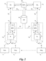
- Fig. 2 when the tag 4 1 communicates a message 7 1 according to the first protocol 10 1 to its "native" reader 5 1 , this first-protocol message 7 1 is present in the "correct" protocol 10 1 at an output 11 of the reader 5 1 .
- the reader 5 1 may be part or member of a lane controller 12 1 , which has an interface 13, which is connected to the output 11 of the reader 5 1 .
- the interface 13 of the lane controller 12 1 is in turn connected to an input 14 of the central station 8 1 responsible for the region 9 1 via a connection 15 1 .
- the reader 5 i is a "multi-protocol" reader meaning that it can receive messages 7 i according to at least two protocols 10 i , 10 i+1 as detailed below, for the central station 8 1 all messages conveyed via the connection 15 1 are present as first-protocol messages 7 1 , so that the central station 8 i needs to and can only parse messages according to its native protocol 10 1 .
- the multi-protocol reader 5 1 detects that a message was received according to the second protocol 10 2 by means of, e.g., the structure of the message 7 2 , and outputs it at an output 16 to the input of a mapping unit 17 1 .
- the mapping unit 17 1 has the task to generate a "new" first-protocol message 7 1 ' upon receiving such a second-protocol message 7 2 , which second protocol 10 2 is not "native" to the region 9 i in which the reader 5 1 is deployed.
- the mapping unit 17 i is connected to a correlation unit 19 via a connection 20.
- the correlation unit 19 can be embodied as a database DB as shown or alternatively as a computing unit executing a pre-defined algorithm. While the following example refers specifically to embodiments using the database DB, the computing unit can be used as the correlation unit 19 to the same effect.
- the mapping unit 17 1 ⁇ After generating such a new first-protocol message 7 1 ' out of a second-protocol message 7 2 , the mapping unit 17 1 ⁇ outputs the new first-protocol message 7 1 ' at an output 18 to the interface 13, from where it is fed to the input 14 of the central station 8 1 via the connection 15. In this way, between the interface 13 of the lane controller 12 1 and the input 14 of the central station 8 1 and within the central station 8 1 , only first-protocol messages 7 1 , 7 1 ' need to be transmitted and processed, regardless of the protocol 10 i of a message 7 i received by the reader 5 1 .
- Figs. 3 and 4 show an exemplary way of generating a new first-protocol message 7 1 ' by means of the mapping unit 17 1 .
- Fig. 3 depicts a predetermined mapping 21 which is used by the mapping unit 17 1 ⁇ to generate a first-protocol message 7 1 ' out of a second-protocol message 7 2 .
- a header 22 is mapped from the beginning of the second-protocol message 7 2 to a new header 22' at the beginning of the new first-protocol message 7 1 '.
- the tag identification TID i is mapped from, e.g., the middle of the second-protocol message 7 2 to, for example, a second data field of the new first-protocol message 7 1 '.
- the second-protocol tag identification TID 2 is replaced by a new first-protocol tag identification TID 1 ' as will be described below by means of Fig. 4 in detail.
- a class data value 23, an HOV (high occupancy vehicle) data value 24, and a version data value 25 are mapped from the second-protocol message 7 2 to a new class data value 23', a new HOV data value 24', and a new version data value 25', e.g., from data fields before the tag identification TID 2 to data fields after the new tag identification TID 1 '.
- the last data field of the second-protocol message 7 2 is, in this case, a CRC (cyclic redundancy check) value 26 of the second-protocol message 7 2 that is validated before mapping.
- a new CRC value 26' is computed as part of generating the new first-protocol message 7 1 ' and added as a last data field to the new first-protocol message 7 1 '. In this way, a new first-protocol message 7 1 ' can be computed out of the second-protocol message 7 2 .
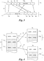
- Fig. 4 shows the content of the database DB used as the correlation unit 19, wherein unique tag identifications TID i of three protocols 10 1 , 10 2 , 10 3 are shown.
- "actual" tag identifications ranging from “00000” to “19999” are shown, which are assigned to tags 4 1 that operate according to the first protocol 10 1 .
- two reserved subsets s 2 , s 3 ranging from "20000” to "29999” and "30000” to "34999", respectively, of the unique tag identifiers TID 1 of the first protocol 10 1 are depicted.
- These reserved subsets s 2 , s 3 contain "virtual" tag identifications TID 1 ' that are not used for tags 4 i deployed in vehicles 3.
- unique tag identifications TID 2 of a second protocol 10 2 are shown, which are again split up into actual and virtual tag identifications TID 2 , TID 2 '.
- unique tag identifications TID 3 of a third protocol 10 3 are shown split up into actual and virtual tag identifications TID 3 , TID 3 '.
- the algorithm could also include if-statements to account for different lengths of tag identifications.
- each actual second-protocol tag identification TID 2 is correlated to one virtual first-protocol tag identification TID 1 '.
- the database DB can store such correlations 27 from the actual tag identifications TID 1 of the first protocol 10 1 to a respective subset s 1 of the second-protocol tag identifications TID 2 and to a respective subset s 1 of third-protocol tag identifications TID 3 (shown in dotted lines), and all other possible correlations (not shown).
- the mapping unit 17 1 generates a new first-protocol message 7 1 ' upon receiving a second-protocol message 7 2 from the reader 5 1 by means of three steps: Firstly, the second-protocol tag identification TID 2 is extracted from the second-protocol message 7 2 . Secondly, that first-protocol tag identification TID 1 that correlates to the extracted second-protocol tag identification TID 2 is retrieved from the database DB according to the correlation 27 in the database DB ( Fig. 4 ).
- said new first-protocol message 7 1 ' is generated by copying information from said second-protocol message 7 2 according to the predetermined mapping 21 between the second protocol 10 2 and the first protocol 10 1 while replacing the second-protocol tag identification TID 2 by the retrieved first-protocol tag identification TID 1 ( Fig. 3 ).
- the vehicles 3 can be identified by means of these messages, in particular by the actual or virtual tag identifications TID 1 , TID 1 ' therein. Identified vehicles 3 can then be tolled on the basis of their locations and/or used roads 2.
- the central station 8 i can detect whether a message 7 i , 7 i ' was mapped by means of the mapping unit 17 i by accessing the database DB via a connection 28. The central station 8 i then checks whether the tag identification TID i stored in a message 7 i , 7 i ' is present in a reserved subset s i as shown in Fig. 4 .
- the central station 8 i can forward this message 7 i ', which was apparently mapped by means of the mapping unit 17 i , to that central station 8 i (here: the "further" central station 8 2 ), which belongs to that reserved subset s i in which the tag identification TID i was found.
- this message can also be mapped back to the protocol 10 i in which it was originally received in the reader 5 i .
- a further mapping unit 29 is located downstream of the central station 8 i , e.g., interposed between the central station 8 1 and the further central station 8 2 .
- the further mapping unit 29 reconstructs the second-protocol message 7 2 as follows.
- the first-protocol tag identification TID 1 is extracted from said detected new first-protocol message 7 1 '.
- the further mapping unit 29 retrieves that second-protocol tag identification TID 2 that correlates (27) to the extracted first-protocol tag identification TID 1 from the database DB.
- said second-protocol message 7 2 is reconstructed by copying information from said new first-protocol message 7 1 ' according to the predetermined mapping 21 between the first protocol 10 1 and the second protocol 10 2 while replacing the first-protocol tag identification TID 1 by the retrieved second-protocol tag identification TID 2 .
- the further mapping unit 29 is connected to the correlation unit 19 via a connection 30.
- the further mapping unit 29 could also be arranged in the central station 8 i that forwards the message 7 1 ', or in that central station 8 1 that receives the message 7 1 '.
- the connection 28 and the connection 30 can be embodied as one.
- the correlation unit 19 could, instead of being a central correlation unit that is connected to each element, be embodied within each central station 8 i or mapping unit 17 i . In the example of Fig. 2 , this would mean that the correlation unit 19 would be present five times in the system, embodied in the mapping units 17 1 , 17 2 , 29 and in the central stations 8 1 , 8 2 .
- Such multiple correlation units 19 embodied as databases DB would then have substantially the same content. In case of any changes, such databases DB could be updated or synchronised, e.g., on a regular basis. If, on the other hand, computing units are used as such multiple correlation units 19, they would then use the same algorithm. In case of any changes, the algorithms of computing units could be updated or synchronised, e.g., on a regular basis.
Landscapes
- Engineering & Computer Science (AREA)
- Physics & Mathematics (AREA)
- Computer Networks & Wireless Communication (AREA)
- General Physics & Mathematics (AREA)
- Signal Processing (AREA)
- Toxicology (AREA)
- Health & Medical Sciences (AREA)
- Business, Economics & Management (AREA)
- Finance (AREA)
- Electromagnetism (AREA)
- General Health & Medical Sciences (AREA)
- Artificial Intelligence (AREA)
- Computer Vision & Pattern Recognition (AREA)
- Theoretical Computer Science (AREA)
- Computer Security & Cryptography (AREA)
- Devices For Checking Fares Or Tickets At Control Points (AREA)
- Mobile Radio Communication Systems (AREA)
Priority Applications (3)
| Application Number | Priority Date | Filing Date | Title |
|---|---|---|---|
| EP17165144.1A EP3385918B1 (fr) | 2017-04-06 | 2017-04-06 | Système et procédé d'identification de véhicule |
| US15/946,363 US10157540B2 (en) | 2017-04-06 | 2018-04-05 | Vehicle identification system and method |
| CA3000384A CA3000384A1 (fr) | 2017-04-06 | 2018-04-05 | Systeme et procede d'identification de vehicule |
Applications Claiming Priority (1)
| Application Number | Priority Date | Filing Date | Title |
|---|---|---|---|
| EP17165144.1A EP3385918B1 (fr) | 2017-04-06 | 2017-04-06 | Système et procédé d'identification de véhicule |
Publications (3)
| Publication Number | Publication Date |
|---|---|
| EP3385918A1 true EP3385918A1 (fr) | 2018-10-10 |
| EP3385918C0 EP3385918C0 (fr) | 2024-03-06 |
| EP3385918B1 EP3385918B1 (fr) | 2024-03-06 |
Family
ID=58709198
Family Applications (1)
| Application Number | Title | Priority Date | Filing Date |
|---|---|---|---|
| EP17165144.1A Active EP3385918B1 (fr) | 2017-04-06 | 2017-04-06 | Système et procédé d'identification de véhicule |
Country Status (3)
| Country | Link |
|---|---|
| US (1) | US10157540B2 (fr) |
| EP (1) | EP3385918B1 (fr) |
| CA (1) | CA3000384A1 (fr) |
Cited By (1)
| Publication number | Priority date | Publication date | Assignee | Title |
|---|---|---|---|---|
| CN110349279A (zh) * | 2019-05-22 | 2019-10-18 | 陈新 | 一种车载电子标签 |
Citations (4)
| Publication number | Priority date | Publication date | Assignee | Title |
|---|---|---|---|---|
| US4808803A (en) * | 1987-08-24 | 1989-02-28 | Figgi International, Inc. | Security system |
| US20030109223A1 (en) * | 2001-11-26 | 2003-06-12 | Kazumasa Toyama | Electronic toll collection system adapted to plural types of protocols employed by various on-vehicle units |
| US20060106671A1 (en) * | 2001-01-31 | 2006-05-18 | Werner Biet | Road roll collection system |
| US20160234313A1 (en) * | 2015-02-09 | 2016-08-11 | General Electric Company | Protocol conversion system and method for a vehicle system |
Family Cites Families (19)
| Publication number | Priority date | Publication date | Assignee | Title |
|---|---|---|---|---|
| FI107501B (fi) * | 1997-01-31 | 2001-08-15 | Nokia Mobile Phones Ltd | Menetelmä käyttäjätunnuksen varaamiseksi |
| US6452915B1 (en) * | 1998-07-10 | 2002-09-17 | Malibu Networks, Inc. | IP-flow classification in a wireless point to multi-point (PTMP) transmission system |
| US7512236B1 (en) * | 2004-08-06 | 2009-03-31 | Mark Iv Industries Corporation | System and method for secure mobile commerce |
| US7966012B2 (en) * | 2004-09-09 | 2011-06-21 | Parkervision, Inc. | Wireless protocol converter |
| DE602005016830D1 (de) * | 2004-11-19 | 2009-11-05 | Sensormatic Electronics Corp | Verfahren und hardware zur kommunikation mit rückstreuungs-rfid-lesern |
| US8322608B2 (en) * | 2005-08-15 | 2012-12-04 | Assa Abloy Ab | Using promiscuous and non-promiscuous data to verify card and reader identity |
| US8967476B2 (en) * | 2005-09-09 | 2015-03-03 | Assa Abloy Ab | Synchronization techniques in multi-technology/multi-frequency RFID reader arrays |
| US8917178B2 (en) * | 2006-06-09 | 2014-12-23 | Dominic M. Kotab | RFID system and method for storing information related to a vehicle or an owner of the vehicle |
| US8751092B2 (en) * | 2011-01-13 | 2014-06-10 | Continental Automotive Systems, Inc. | Protocol protection |
| US9097614B2 (en) * | 2012-01-18 | 2015-08-04 | Xerox Corporation | Vehicle emissions testing and toll collection system |
| WO2014085617A1 (fr) * | 2012-11-27 | 2014-06-05 | Geist Wyatt D | Procédé et appareil pour fournir un service de péage et dispositif de péage flexible |
| US9635146B2 (en) * | 2014-06-19 | 2017-04-25 | Cavium, Inc. | Method of using bit vectors to allow expansion and collapse of header layers within packets for enabling flexible modifications and an apparatus thereof |
| US9429436B2 (en) * | 2015-01-13 | 2016-08-30 | Toyota Motor Engineering & Manufacturing North America, Inc. | Estimated time of arrival for vehicle navigation |
| CN108136963B (zh) * | 2015-10-22 | 2021-04-27 | 金泰克斯公司 | 集成车辆通信系统和方法 |
| US9786109B2 (en) * | 2015-12-17 | 2017-10-10 | Nxp B.V. | Use of a biphase code matched filter to receive protocols with code violations |
| US20180012196A1 (en) * | 2016-07-07 | 2018-01-11 | NextEv USA, Inc. | Vehicle maintenance manager |
| US20180025551A1 (en) * | 2016-07-21 | 2018-01-25 | Highway Toll Administration, Llc | Vehicle toll usage tracking system and method |
| US10078950B2 (en) * | 2016-07-25 | 2018-09-18 | Symbol Technologies, Llc | Remotely configurable location tracking tags |
| US9922473B1 (en) * | 2017-01-23 | 2018-03-20 | UScontracting, Inc. | Systems and methods for location-based automated authentication |
-
2017
- 2017-04-06 EP EP17165144.1A patent/EP3385918B1/fr active Active
-
2018
- 2018-04-05 US US15/946,363 patent/US10157540B2/en active Active
- 2018-04-05 CA CA3000384A patent/CA3000384A1/fr active Pending
Patent Citations (4)
| Publication number | Priority date | Publication date | Assignee | Title |
|---|---|---|---|---|
| US4808803A (en) * | 1987-08-24 | 1989-02-28 | Figgi International, Inc. | Security system |
| US20060106671A1 (en) * | 2001-01-31 | 2006-05-18 | Werner Biet | Road roll collection system |
| US20030109223A1 (en) * | 2001-11-26 | 2003-06-12 | Kazumasa Toyama | Electronic toll collection system adapted to plural types of protocols employed by various on-vehicle units |
| US20160234313A1 (en) * | 2015-02-09 | 2016-08-11 | General Electric Company | Protocol conversion system and method for a vehicle system |
Cited By (2)
| Publication number | Priority date | Publication date | Assignee | Title |
|---|---|---|---|---|
| CN110349279A (zh) * | 2019-05-22 | 2019-10-18 | 陈新 | 一种车载电子标签 |
| CN110349279B (zh) * | 2019-05-22 | 2021-06-11 | 蔡欧 | 一种车载电子标签 |
Also Published As
| Publication number | Publication date |
|---|---|
| EP3385918C0 (fr) | 2024-03-06 |
| EP3385918B1 (fr) | 2024-03-06 |
| CA3000384A1 (fr) | 2018-10-06 |
| US20180293882A1 (en) | 2018-10-11 |
| US10157540B2 (en) | 2018-12-18 |
Similar Documents
| Publication | Publication Date | Title |
|---|---|---|
| CN107145980B (zh) | 无人车配送方法、系统和控制服务器 | |
| CN108382329B (zh) | 先进的v2x事件传播 | |
| CN103890823B (zh) | 传输用于交通远程信息处理的路线数据的方法及处理单元 | |
| CN105318889A (zh) | 出发地与目的地提取装置、出发地与目的地提取方法 | |
| US20200260239A1 (en) | Method and apparatus for vehicle-to-vehicle message service | |
| CN109788515B (zh) | 一种数据协同方法、mec设备以及服务器 | |
| CN105070089A (zh) | 一种人车路协同的个性化交通信息服务系统及方法 | |
| JP2008046820A (ja) | 運行管理システム及び隊列走行装置 | |
| US10157540B2 (en) | Vehicle identification system and method | |
| CN115376339A (zh) | 一种交通预警方法和系统 | |
| KR101651752B1 (ko) | 열차 자동 등록을 수행하는 통신기반 열차 제어 시스템 및 그 등록 방법 | |
| KR102149527B1 (ko) | 다수 차량의 군집 주행을 위한 운행정보 제공장치 및 그 방법 | |
| CN108778891A (zh) | 集成火车控制和司机咨询系统 | |
| CN104380281A (zh) | 使用项目序列表作为标识符的方法和装置 | |
| EP3082099A1 (fr) | Systeme de prestations de service de voyage intermodal pour la communication avec une pluralite de prestataires de service de transport et de voyage | |
| KR100924829B1 (ko) | 노선 안내시스템 및 방법 | |
| US20210166175A1 (en) | Determining at least one schedule for at least one transport from a plurality of transport | |
| CN111212133A (zh) | 车辆远程交互事件跟踪系统 | |
| US20230038375A1 (en) | Itinerary Generation Apparatus, Itinerary Generation System, Itinerary Generation Method and Computer Program Product | |
| KR101283358B1 (ko) | 순서표의 항목 순서를 식별자로 이용하는 방법 및 장치 | |
| CN108289200A (zh) | 一种用于交通事故处理的智能处理方法 | |
| KR101983798B1 (ko) | 차량간 메시지 서비스 방법 및 장치 | |
| DE102016124007A1 (de) | Verfahren zur Übertragung einer Nachricht | |
| EP4358055A1 (fr) | Procédé d'interaction et appareil d'interaction | |
| US20220261719A1 (en) | Sharing management device, terminal, sharing management method, and recording medium |
Legal Events
| Date | Code | Title | Description |
|---|---|---|---|
| PUAI | Public reference made under article 153(3) epc to a published international application that has entered the european phase |
Free format text: ORIGINAL CODE: 0009012 |
|
| STAA | Information on the status of an ep patent application or granted ep patent |
Free format text: STATUS: THE APPLICATION HAS BEEN PUBLISHED |
|
| AK | Designated contracting states |
Kind code of ref document: A1 Designated state(s): AL AT BE BG CH CY CZ DE DK EE ES FI FR GB GR HR HU IE IS IT LI LT LU LV MC MK MT NL NO PL PT RO RS SE SI SK SM TR |
|
| AX | Request for extension of the european patent |
Extension state: BA ME |
|
| STAA | Information on the status of an ep patent application or granted ep patent |
Free format text: STATUS: REQUEST FOR EXAMINATION WAS MADE |
|
| 17P | Request for examination filed |
Effective date: 20181010 |
|
| RBV | Designated contracting states (corrected) |
Designated state(s): AL AT BE BG CH CY CZ DE DK EE ES FI FR GB GR HR HU IE IS IT LI LT LU LV MC MK MT NL NO PL PT RO RS SE SI SK SM TR |
|
| STAA | Information on the status of an ep patent application or granted ep patent |
Free format text: STATUS: EXAMINATION IS IN PROGRESS |
|
| 17Q | First examination report despatched |
Effective date: 20200909 |
|
| STAA | Information on the status of an ep patent application or granted ep patent |
Free format text: STATUS: EXAMINATION IS IN PROGRESS |
|
| GRAP | Despatch of communication of intention to grant a patent |
Free format text: ORIGINAL CODE: EPIDOSNIGR1 |
|
| STAA | Information on the status of an ep patent application or granted ep patent |
Free format text: STATUS: GRANT OF PATENT IS INTENDED |
|
| RIC1 | Information provided on ipc code assigned before grant |
Ipc: H04W 4/44 20180101ALI20230925BHEP Ipc: G08G 1/017 20060101ALI20230925BHEP Ipc: G07B 15/06 20110101AFI20230925BHEP |
|
| INTG | Intention to grant announced |
Effective date: 20231016 |
|
| GRAS | Grant fee paid |
Free format text: ORIGINAL CODE: EPIDOSNIGR3 |
|
| GRAA | (expected) grant |
Free format text: ORIGINAL CODE: 0009210 |
|
| STAA | Information on the status of an ep patent application or granted ep patent |
Free format text: STATUS: THE PATENT HAS BEEN GRANTED |
|
| AK | Designated contracting states |
Kind code of ref document: B1 Designated state(s): AL AT BE BG CH CY CZ DE DK EE ES FI FR GB GR HR HU IE IS IT LI LT LU LV MC MK MT NL NO PL PT RO RS SE SI SK SM TR |
|
| REG | Reference to a national code |
Ref country code: GB Ref legal event code: FG4D |
|
| REG | Reference to a national code |
Ref country code: CH Ref legal event code: EP |
|
| REG | Reference to a national code |
Ref country code: DE Ref legal event code: R096 Ref document number: 602017079713 Country of ref document: DE |
|
| REG | Reference to a national code |
Ref country code: IE Ref legal event code: FG4D |
|
| U01 | Request for unitary effect filed |
Effective date: 20240320 |
|
| U07 | Unitary effect registered |
Designated state(s): AT BE BG DE DK EE FI FR IT LT LU LV MT NL PT SE SI Effective date: 20240328 |