EP3385185B1 - Couvercle de boîte métallique - Google Patents
Couvercle de boîte métallique Download PDFInfo
- Publication number
- EP3385185B1 EP3385185B1 EP17165040.1A EP17165040A EP3385185B1 EP 3385185 B1 EP3385185 B1 EP 3385185B1 EP 17165040 A EP17165040 A EP 17165040A EP 3385185 B1 EP3385185 B1 EP 3385185B1
- Authority
- EP
- European Patent Office
- Prior art keywords
- lid
- region
- opening
- accordance
- film
- Prior art date
- Legal status (The legal status is an assumption and is not a legal conclusion. Google has not performed a legal analysis and makes no representation as to the accuracy of the status listed.)
- Active
Links
- 238000007789 sealing Methods 0.000 claims description 52
- 239000000463 material Substances 0.000 claims description 42
- 229910052751 metal Inorganic materials 0.000 claims description 30
- 239000002184 metal Substances 0.000 claims description 30
- 238000000034 method Methods 0.000 claims description 30
- 239000000853 adhesive Substances 0.000 claims description 25
- 230000001070 adhesive effect Effects 0.000 claims description 25
- 230000008569 process Effects 0.000 claims description 23
- 239000004922 lacquer Substances 0.000 claims description 21
- 239000004033 plastic Substances 0.000 claims description 21
- 239000002131 composite material Substances 0.000 claims description 14
- 229910000838 Al alloy Inorganic materials 0.000 claims description 9
- 229910052782 aluminium Inorganic materials 0.000 claims description 9
- XAGFODPZIPBFFR-UHFFFAOYSA-N aluminium Chemical compound [Al] XAGFODPZIPBFFR-UHFFFAOYSA-N 0.000 claims description 9
- 239000007769 metal material Substances 0.000 claims description 9
- 238000004519 manufacturing process Methods 0.000 claims description 8
- 238000004080 punching Methods 0.000 claims description 7
- 239000000314 lubricant Substances 0.000 claims description 6
- 230000002093 peripheral effect Effects 0.000 claims description 6
- 230000003313 weakening effect Effects 0.000 claims description 6
- 235000013361 beverage Nutrition 0.000 claims description 5
- 235000013305 food Nutrition 0.000 claims description 5
- 239000007788 liquid Substances 0.000 claims description 4
- 230000009467 reduction Effects 0.000 claims description 4
- 239000005028 tinplate Substances 0.000 claims description 4
- 229910045601 alloy Inorganic materials 0.000 claims description 3
- 239000000956 alloy Substances 0.000 claims description 3
- 238000005260 corrosion Methods 0.000 claims description 3
- 230000007797 corrosion Effects 0.000 claims description 3
- 239000003566 sealing material Substances 0.000 claims description 3
- 230000000295 complement effect Effects 0.000 claims description 2
- 239000012943 hotmelt Substances 0.000 claims description 2
- 230000001050 lubricating effect Effects 0.000 claims description 2
- 235000011837 pasties Nutrition 0.000 claims description 2
- 239000012265 solid product Substances 0.000 claims description 2
- 239000011324 bead Substances 0.000 claims 1
- 238000004023 plastic welding Methods 0.000 claims 1
- 239000002985 plastic film Substances 0.000 description 7
- 229920006255 plastic film Polymers 0.000 description 7
- 230000008901 benefit Effects 0.000 description 6
- 239000004743 Polypropylene Substances 0.000 description 4
- 239000011859 microparticle Substances 0.000 description 4
- -1 polypropylene Polymers 0.000 description 4
- 229920001155 polypropylene Polymers 0.000 description 4
- 230000003993 interaction Effects 0.000 description 3
- 239000002966 varnish Substances 0.000 description 3
- 230000015572 biosynthetic process Effects 0.000 description 2
- 238000010276 construction Methods 0.000 description 2
- 239000006223 plastic coating Substances 0.000 description 2
- 239000002318 adhesion promoter Substances 0.000 description 1
- 238000004873 anchoring Methods 0.000 description 1
- 238000004140 cleaning Methods 0.000 description 1
- 239000000356 contaminant Substances 0.000 description 1
- 230000008878 coupling Effects 0.000 description 1
- 238000010168 coupling process Methods 0.000 description 1
- 238000005859 coupling reaction Methods 0.000 description 1
- 230000000694 effects Effects 0.000 description 1
- 238000005516 engineering process Methods 0.000 description 1
- 230000036541 health Effects 0.000 description 1
- 239000012535 impurity Substances 0.000 description 1
- 230000007246 mechanism Effects 0.000 description 1
- 239000002991 molded plastic Substances 0.000 description 1
- 238000010137 moulding (plastic) Methods 0.000 description 1
- 238000005457 optimization Methods 0.000 description 1
- 238000004806 packaging method and process Methods 0.000 description 1
- 238000003825 pressing Methods 0.000 description 1
- 239000000047 product Substances 0.000 description 1
- 238000000926 separation method Methods 0.000 description 1
Images


Classifications
-
- B—PERFORMING OPERATIONS; TRANSPORTING
- B65—CONVEYING; PACKING; STORING; HANDLING THIN OR FILAMENTARY MATERIAL
- B65D—CONTAINERS FOR STORAGE OR TRANSPORT OF ARTICLES OR MATERIALS, e.g. BAGS, BARRELS, BOTTLES, BOXES, CANS, CARTONS, CRATES, DRUMS, JARS, TANKS, HOPPERS, FORWARDING CONTAINERS; ACCESSORIES, CLOSURES, OR FITTINGS THEREFOR; PACKAGING ELEMENTS; PACKAGES
- B65D17/00—Rigid or semi-rigid containers specially constructed to be opened by cutting or piercing, or by tearing of frangible members or portions
- B65D17/28—Rigid or semi-rigid containers specially constructed to be opened by cutting or piercing, or by tearing of frangible members or portions at lines or points of weakness
- B65D17/401—Rigid or semi-rigid containers specially constructed to be opened by cutting or piercing, or by tearing of frangible members or portions at lines or points of weakness characterised by having the line of weakness provided in an end wall
- B65D17/4012—Rigid or semi-rigid containers specially constructed to be opened by cutting or piercing, or by tearing of frangible members or portions at lines or points of weakness characterised by having the line of weakness provided in an end wall for opening partially by means of a tearing tab
- B65D17/4014—Rigid or semi-rigid containers specially constructed to be opened by cutting or piercing, or by tearing of frangible members or portions at lines or points of weakness characterised by having the line of weakness provided in an end wall for opening partially by means of a tearing tab and provided with attached means for reclosing or resealing
-
- B—PERFORMING OPERATIONS; TRANSPORTING
- B23—MACHINE TOOLS; METAL-WORKING NOT OTHERWISE PROVIDED FOR
- B23P—METAL-WORKING NOT OTHERWISE PROVIDED FOR; COMBINED OPERATIONS; UNIVERSAL MACHINE TOOLS
- B23P15/00—Making specific metal objects by operations not covered by a single other subclass or a group in this subclass
-
- B—PERFORMING OPERATIONS; TRANSPORTING
- B65—CONVEYING; PACKING; STORING; HANDLING THIN OR FILAMENTARY MATERIAL
- B65D—CONTAINERS FOR STORAGE OR TRANSPORT OF ARTICLES OR MATERIALS, e.g. BAGS, BARRELS, BOTTLES, BOXES, CANS, CARTONS, CRATES, DRUMS, JARS, TANKS, HOPPERS, FORWARDING CONTAINERS; ACCESSORIES, CLOSURES, OR FITTINGS THEREFOR; PACKAGING ELEMENTS; PACKAGES
- B65D2517/00—Containers specially constructed to be opened by cutting, piercing or tearing of wall portions, e.g. preserving cans or tins
- B65D2517/0001—Details
- B65D2517/001—Action for opening container
- B65D2517/0013—Action for opening container pull-out tear panel, e.g. by means of a tear-tab
-
- B—PERFORMING OPERATIONS; TRANSPORTING
- B65—CONVEYING; PACKING; STORING; HANDLING THIN OR FILAMENTARY MATERIAL
- B65D—CONTAINERS FOR STORAGE OR TRANSPORT OF ARTICLES OR MATERIALS, e.g. BAGS, BARRELS, BOTTLES, BOXES, CANS, CARTONS, CRATES, DRUMS, JARS, TANKS, HOPPERS, FORWARDING CONTAINERS; ACCESSORIES, CLOSURES, OR FITTINGS THEREFOR; PACKAGING ELEMENTS; PACKAGES
- B65D2517/00—Containers specially constructed to be opened by cutting, piercing or tearing of wall portions, e.g. preserving cans or tins
- B65D2517/0001—Details
- B65D2517/0031—Reclosable openings
- B65D2517/0038—Reclosable openings the plug being reinsertable into the opening
-
- B—PERFORMING OPERATIONS; TRANSPORTING
- B65—CONVEYING; PACKING; STORING; HANDLING THIN OR FILAMENTARY MATERIAL
- B65D—CONTAINERS FOR STORAGE OR TRANSPORT OF ARTICLES OR MATERIALS, e.g. BAGS, BARRELS, BOTTLES, BOXES, CANS, CARTONS, CRATES, DRUMS, JARS, TANKS, HOPPERS, FORWARDING CONTAINERS; ACCESSORIES, CLOSURES, OR FITTINGS THEREFOR; PACKAGING ELEMENTS; PACKAGES
- B65D2517/00—Containers specially constructed to be opened by cutting, piercing or tearing of wall portions, e.g. preserving cans or tins
- B65D2517/0001—Details
- B65D2517/0031—Reclosable openings
- B65D2517/0046—Unusual reclosable openings
-
- B—PERFORMING OPERATIONS; TRANSPORTING
- B65—CONVEYING; PACKING; STORING; HANDLING THIN OR FILAMENTARY MATERIAL
- B65D—CONTAINERS FOR STORAGE OR TRANSPORT OF ARTICLES OR MATERIALS, e.g. BAGS, BARRELS, BOTTLES, BOXES, CANS, CARTONS, CRATES, DRUMS, JARS, TANKS, HOPPERS, FORWARDING CONTAINERS; ACCESSORIES, CLOSURES, OR FITTINGS THEREFOR; PACKAGING ELEMENTS; PACKAGES
- B65D2517/00—Containers specially constructed to be opened by cutting, piercing or tearing of wall portions, e.g. preserving cans or tins
- B65D2517/50—Non-integral frangible members applied to, or inserted in, a preformed opening
- B65D2517/5002—Details of flexible tape or foil-like material
- B65D2517/5024—Material
- B65D2517/5027—Single layer
-
- B—PERFORMING OPERATIONS; TRANSPORTING
- B65—CONVEYING; PACKING; STORING; HANDLING THIN OR FILAMENTARY MATERIAL
- B65D—CONTAINERS FOR STORAGE OR TRANSPORT OF ARTICLES OR MATERIALS, e.g. BAGS, BARRELS, BOTTLES, BOXES, CANS, CARTONS, CRATES, DRUMS, JARS, TANKS, HOPPERS, FORWARDING CONTAINERS; ACCESSORIES, CLOSURES, OR FITTINGS THEREFOR; PACKAGING ELEMENTS; PACKAGES
- B65D2517/00—Containers specially constructed to be opened by cutting, piercing or tearing of wall portions, e.g. preserving cans or tins
- B65D2517/50—Non-integral frangible members applied to, or inserted in, a preformed opening
- B65D2517/5072—Details of hand grip, tear- or lift-tab
- B65D2517/5075—Hand grip with finger opening
- B65D2517/5078—Hand grip with finger opening finger opening edge rolled or folded over
Definitions
- the present invention relates to a metallic can lid with a reclosable opening, in particular for beverage cans and for containers for storing food and other liquid, pasty, powdery and / or solid products.
- the plastic closure part comprises a base part to be connected to the flanged edge of the can opening, in which base part an opening is formed which is closed by a flat plug.
- the flat plug is connected to the opening edge via a plastic tear seam, so that the flat plug connected to a pull tab can be released from the plastic base part by pulling on the pull tab and pivoted into an opening point.
- the opening can be temporarily closed again by pressing in the flat plug, which is preferably conical on its underside.
- Resealable can lids are also for example in the DE 10 2010 013 531 A1 and the EP 2 354 022 B1 described.
- the object of the invention is therefore to design the known reclosable can lid in such a way that its manufacture is possible in an even more economical manner, the construction is simplified, material savings can be achieved and at the same time the function is improved.
- a metallic can lid with a micro-gap provided in the metallic lid surface, through a circumferential micro-gap sealed by a film with a notch in the film adjacent to it, a sealing frame made of plastic material connected to the fixed lid surface and enclosing the opening area , a sealing unit made of plastic material connected to the swiveling metallic lid area located within the micro-gap, which is pivotably attached to the fixed lid surface and diametrically opposite the pivot bearing area is provided with a tear-open element, the sealing frame and the closing unit interacting via sealing and locking ribs and associated receiving grooves and the metallic lid area located within the annular micro-gap, in particular in a form-fitting and non-positive manner and in particular without teeth, in the opening ungs range of the lid is received and held, and wherein the provided on the inside of the lid, the micro-gap covering film consists of a molded part, in particular a deep-drawn molded part, which reproduces the
- the interaction of the individual features of the can lid according to the invention makes it possible to accommodate and fasten both the sealing frame and the closing unit in a space-saving manner and preferably in a recess in the can lid surface on the top of the can lid, and thus to avoid the openings of the can lid surface required in known constructions.
- This also brings advantages in terms of hygiene, in particular in connection with the further special feature of the invention, which consists in the fact that the closure unit has a sealing apron on its entire outer circumference which extends to the fixed cover surface and which is preferably integrally connected to the fixed cover surface via the adhesive lacquer layer is.
- the underside of the metallic can lid located on the inside of the can which is formed by a practically continuous metal surface that only contains the micro-gap, is in turn cohesively connected to the plastic film molded part that ensures the sealing of the micro-gap, whereby it is important that none to the sealing unit or Plastic parts belonging to the sealing frame extend through the metallic cover material and accordingly only two components on the underside of the cover, namely the metallic cover on the one hand and the molded plastic part on the other hand, have to come into contact with one another and have to be connected.
- a further advantage is the preferred use of a toothing or undercut-free assembly of the swiveling lid area that was initially punched out of the lid area and then pushed back into the lid area, the knowledge being used that the punching out process can be designed in such a way that a conical widening can be achieved in the cover material over a partial area of the material thickness, which allows a positive and / or non-positive connection between the fixed cover surface and the punched-out cover area while forming the desired micro-gap.
- the integral connection can in particular consist of a plastic welded connection, the adhesive lacquer serving to promote adhesion between plastic and metal, or a so-called hot-melt connection.
- the sealing frame, the closing unit and the molded film part are exactly aligned with one another with respect to the metallic cover surface by means of preferably punctiform positioning knobs and associated, in particular cup-shaped depressions.
- knobs for the plastic parts positioned on the outside of the can lid are preferably formed on this plastic part
- the cup-shaped recesses for receiving the knobs of the sealing frame on the underside or inside of the lid simultaneously act as knobs for positioning the plastic molding, which is correspondingly complementary Has depressions.
- the finished can lid preferably consists of a composite material in the form of a sheet metal layer coated on both sides with an adhesive varnish and internally connected to the film molded part via the adhesive varnish layer, in particular from aluminum or tinplate, the mechanical strength of the film component in the composite material being expediently chosen such that while ensuring the required total strength of the composite material, the material thickness of the metallic component can be reduced compared to a film-free component, in particular can be reduced by at least 1%.
- the film molded part of the composite material extends into the flange edge provided for connecting the lid to a can and acts there as a sealing material and corrosion protection.
- the measure according to the invention can in turn achieve a practically relevant saving and cost reduction.
- the swivel bearing area formed on the closing unit has between its fastening area and the swiveling part a bracket area which is closed on the lid side, which extends on both sides in a gusset manner and acts as a toggle spring and which enables bistable positioning of the closing unit.
- This arrangement ensures that when an opening angle of approximately 90 ° is exceeded, the closing unit is moved to an opening angle of more than 130 ° and is kept open in this position, while when the angle falls below an angle of approximately 90 ° from the open position, the closing unit opens snaps back an opening angle position of less than 30 °. From this position, the closing unit can be pressed into the sealing closed position again without any problems. This process can be carried out reversibly several times in both directions.
- sealing frame and sealing unit are of particular importance for the function of the reclosable can lid according to the invention.
- Sealing frame and closing unit work together via an internal sealing rib and an external locking rib, which engage in corresponding receiving grooves. Between the sealing rib and a wall of the associated receiving groove, a predeterminable inclined surface / sealing pair is provided, the choice of the incline depending on which internal pressure of the can must be withstood after the can has been resealed, while at the same time it must be taken into account that the opening process is not disturbing is difficult.
- the locking rib is provided with a short inclined surface approach, which cooperates with a counter-locking of the associated receiving groove, with a predetermined play being provided between the two interacting surfaces when the can opening is closed.
- This slight play can be used to enable overpressure relief during the opening movement of the closing unit, without the cover already being opened so far in this phase that there is a risk of liquid being sprayed out.
- a further special feature of the invention which is important with regard to the always desired reduction in the manufacturing costs of can lids, is that the can lid consists at least essentially of the same aluminum alloy as the container part connected to it and the metallic material thickness of the can lid is essentially equal to the material thickness of the Part of the container is and preferably does not exceed at least twice the material thickness of the container part, the material thickness of the container part being in the range of approximately 0.1 mm and less.
- Known cans in particular beverage cans, consist of aluminum alloys, it being customary to use an aluminum alloy of the 3000 series for the cylindrical can part and an aluminum alloy of the 5000 series for the lid part in order to take into account the different technical requirements with regard to the can part and the lid part.
- series 3000 aluminum alloy which is cheaper than series 5000 aluminum alloy, which is usually used as a lid material.
- the wall thickness of the lid material must be at least twice as large as the material thickness of the can wall in order to ensure the necessary pressure resistance of the can despite the notch to be formed in the lid material in known lids to create a tear-open groove.
- This notch has a depth that is typically about half the material thickness of the can lid.
- the invention relates to a method according to claim 14, for producing a tight, tearable or compressible and preferably reclosable opening in a can lid, which is designed to be reclosable, in which the opening area can either be torn open or can be pressed into the interior of the can.
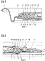
- FIG. 1 shows a can lid 1 intended in particular for a beverage can, in the lid surface of which a reclosable opening system is integrated.
- a lid area 10 is provided in the can lid, which can be opened and pivoted up by means of a tear-open element 17 by means still to be described and described in detail, specifically via a pivot bearing area, the fixed part 19 of which is fastened to the can lid.
- a toggle spring section 21 is provided between this fixed part 19 and a closing unit 11 firmly connected to the metallic cover area 10, which allows the closing unit 11 to be opened when an opening angle of approx. 90 ° is exceeded to more than 130 °, i.e. to snap the capping unit into its final opening position. If the closing unit falls below an opening angle of approx.
- the closing unit snaps back to an opening angle of less than 30 °, and from this partial opening position the closing unit can be manually pushed back into the sealing closed position without any problems.
- This process can be carried out reversibly several times in both directions.
- the can lid 1 is preferably connected to the associated container via a flange 3.
- FIG. 1 The side view of the can lid 1 after Fig. 1 illustrates that the closure and opening system according to the invention is of such a flat design that it is completely accommodated within the depth of the lid part and that no parts protrude beyond the lid contour in the closed position.
- Fig. 3 shows a section through the lid Fig. 1 corresponding to section line AA, the areas of detail which are particularly important for structure and function being identified by B and C, which are explained in detail below.
- the detail D shown shows in a greatly enlarged manner the structural structure of a main component of the can lid in the form of a composite material.
- This main component of the can lid consists of a suitably shaped sheet metal layer 5 made of aluminum or tinplate, and this sheet metal layer is provided on both sides with an adhesive lacquer layer 7, which serves as an adhesion promoter and enables a high-strength and permanent material connection between metal, in particular aluminum and the preferably to ensure the polypropylene plastic of the film 6, that is on the underside of the lid, ie is provided on the inside of the can and is suitable for food.
- the mutual connection of the individual components of the composite material is preferably carried out in a so-called hot-sealing process, in which the plastic is melted, so that there is a material connection with the metal.
- the material thickness of the metal can lid part can already be reduced due to the use of the micro-gap technology already described in the introduction in contrast to can lids with a tearable scoring line, it is advantageous to use the described composite material, since the composite material allows it without sacrificing the required strength values To further reduce the material thickness of the sheet metal layer and thereby achieve significant material and cost savings in practice.
- Fig. 4 shows the area B enlarged Fig. 3 , ie the area to which the tear-open member 17 is fastened to the cover part which can be swung open, specifically on the outer edge thereof, so that when the cover part is pulled up also due to the Elasticity of the lid material in particular results in a lever effect, which favors the opening of the lid part.
- the molded part contour of the plastic film 6 which is integrally connected to the sheet metal layer 5 via the adhesive lacquer layer 7 corresponds to the contour of the underside of the sheet metal cover part 5 and preferably extends into the flared area 3, where it can simultaneously act as a seal and corrosion protection.
- pivoted lid area 10 is provided, which according to the invention is not limited by a material weakening, as in the usual prior art, but rather by a micro-gap 8.
- This circumferential micro-gap 8 is preferably formed by punching the lid area 10 out of the sheet metal material and then pushing it back into the opening and holding it by clamping, so that again a flat metal surface is present and the metallic lid, which is provided with an adhesive lacquer layer on both sides, is again a uniform one Part can be handled.
- the micro-gap 8 which is preferably formed by a straight or curved and toothless line, is underside, i.e. Covered on the inside of the cover by the plastic film and thus sealed.
- the plastic film which preferably consists of food-grade polypropylene, has a notch 9 adjacent to the micro-gap, which notch can have the same or possibly different depth all round and ensures that only a comparatively small force is required to open the lid.
- the distance between the micro gap 8 and the notch 9 is preferably about twice the film thickness, that is to say, for example, 3 to 4 tenths of a millimeter.
- the opening force required depends not only on the force required to separate the connection between the sheet metal layer 5 and the plastic film 6 in the area of the micro-gap 8, but also on the pair of seals which is realized in the interaction of the sealing frame 14 and the closing unit 11.
- the sealing frame 14 made of plastic material, in particular polypropylene, surrounds the opening area and is, preferably in a recess in the sheet metal layer 5, firmly connected to the metallic cover material via the adhesive lacquer layer 7 already mentioned. It is possible to provide this fixed connection only in the bottom area of the recess.
- the sealing frame 14 has two receiving grooves 15, 16 separated from one another by a central web 20 for a locking rib 12 and a sealing rib 13, which are provided on the closing unit 11.
- This closure unit 11, which is also made of plastic material, preferably polypropylene, is firmly connected to the metallic lid analogously to the sealing frame 14, but not to the stationary lid surface 2, but rather to the hinged lid region 10.
- the hinged lid part is thus separated from the one by the micro-gap 8 limited metallic lid area 10 and the edge thereof attached closing unit 11 is formed, on which the tear member 17 is integrally formed.
- This tear-open member 17, which is connected to the outer edge of the closing unit 11, is provided with a holding or fixing element 22, which extends towards the cover part and is fixed there in an easily detachable manner, so that the integrity of the respective packaging can be easily checked on the basis of this connection.
- a diametrically opposed opening member 17 has a pivot bearing region 18 formed on this frame on the closing unit 11, which is firmly connected to the cover surface located outside the cover part which can be pivoted open, which is also shown in FIG Fig. 5 is explained.
- Fig. 5 shows the detail area C in an enlarged view Fig. 3 , ie the swivel bearing area 18 diametrically opposite the tear-open member 17 in connection with the sealing frame and closing unit 11, which in the closed state of the can lid are engaged with one another in the manner shown and form a tight snap-snap connection.
- the rib 13 received in the receiving groove 16 and the rib 12 received in the receiving groove 15 are different, that is to say there are at least partially separate functions, which enables an optimization of the interaction of the sealing frame 14 and the closing unit 11.
- the closing unit 11 is connected to the fixed part of the pivot bearing via an integrated, bistable toggle spring section 21. This keeps the lid part, consisting of the metallic lid area 10, the fastening unit 11 attached to it and the tear-open member 17 open when exceeding approximately 90 ° to more than 130 °, so that the interior of the respective container is optimally accessible.
- the cover part snaps back to an opening angle of less than 30 °. From this open position it can Cover part can be transferred or pressed back into the sealing closed position. This process can be carried out reversibly several times in both directions.
- the pivot bearing area 18 represents a practically closed area, i.e. the gaps and openings which are frequently present, especially in the tilting spring area in known solutions, are avoided.
- the closure unit 11 is provided on its entire outer circumference with a sealing apron 26 which extends to the fixed cover surface 2 and which is preferably integrally connected to the cover surface 2 via the adhesive lacquer layer. In this way, it is safely prevented that any contaminants, moisture and the like can get under the plastic elements, i.e. In terms of hygiene, an optimum is achieved which is not the case with conventional reclosable can lids of this type. This connection is disconnected the first time it is opened.
- sealing rib 13 forms a pair of sealing surfaces 23 with the receiving groove 16. This pair of sealing surfaces 23 contributes to the snap-in process during the closing process and holds the closing unit in a defined position in the closed state.
- the opening resistance can also be set, ie an inclined surface pairing can be selected which ensures that, on the one hand, the internal pressure that occurs occurs and, on the other hand, the opening process is not made too difficult.
- the locking rib 12 and the associated receiving groove 15 also have short, interacting inclined surfaces which, on the one hand, secure the locking snap, but on the other hand also enable a small free relative movement in the form of play 25 between the counter-locking element 24 and the short inclined surface provided on the locking rib 12.
- This free mobility can be used to allow a small initial opening movement when the can lid is opened repeatedly, in which case any internal pressure is released without the lid already being opened so far that liquid could escape in a potentially disruptive manner.
- the schematic representation after Fig. 7 illustrates a preferably used process of punching the lid area 10 out of the sheet metal layer 5 and then or later inserting the punched area into the opening formed.
- the specially selected punching process that is to say the special choice of stamp and die, means that the circumferential contour of the punched-out area, viewed over its thickness, has a smooth-cut section and an oblique-cut section, which make it possible or easier to remove the punched-out sheet-metal layer area immediately or at a later point in time again in the punched-out opening, in such a way that the punched-out area is held in the opening with sufficient clamping for further processing.
- the punch and die are preferably selected such that the resulting smooth cut section extends over less than 50% of the material thickness and the remaining bevel cut section widens essentially conically. As a result, a sufficient frictional connection is achieved when the punched-out part is inserted or pressed back into the sheet-metal layer, and it is no longer necessary to provide special toothing or undercuts between the punched-out part and the sheet-metal layer in order to achieve the necessary holding forces.
- the reclosable can lid according to the invention is also advantageous because the tear-open member 17, which is preferably designed as a ring tab, is easily accessible, can be easily gripped and enables the respective can to be opened via a convenient pulling movement.
- the advantage of reclosing is that the complete reclosing can preferably be felt by the snap-in connection and is also acoustically perceptible.
- the can lid according to the invention can be used for all types of containers which are to be reclosable, the tight connection of the can lid with the respective container not only via a flanged edge, but especially in the case of non-metallic containers also via adhesive connections, welded connections and the like.
- the invention is also directed to a method for producing a dense, tearable or compressible and preferably reclosable opening in a sheet metal material, in particular in a can lid, as described in detail in claims 14 to 18.
- This manufacturing process which works with a sheet metal layer which is preferably coated on both sides with a food-grade adhesive lacquer layer, is suitable both for the production of can lids of the type described in the context of this invention and also for the production of standard can lids.
- a two-armed lever member is provided for opening the respective opening area, which is firmly connected to the lid material.
- the opening area is designed as a tongue tab, which is separated from the lid surface by a micro-gap extending over the tab periphery, the tongue tab base connected to the lid surface forming a kink bearing that becomes effective during the opening process.
- the underside of the metal cover is laminated or laminated with a plastic film.
- This film is weakened adjacent to the micro-gap to ensure problem-free opening of the respective can. If the arrangement is such that the tongue flap is pivoted into the interior of the can during the opening process together with the partial area of the plastic coating that covers it on the underside and delimits the weakening line, the weakening line is located outside the micro-gap.
- the weakening line is located within the micro-gap. Details of such standard can lids are in the German patent application DE 10 2015 122 548.4 described.
- the method according to the invention can be designed in connection with reclosable can lids of the type described in such a way that the punched-out lid part is pressed directly into the sheet metal layer by spring force in the course of the return stroke and is held there non-positively, but it is also possible to separately feed the sheet metal layer on the one hand and the punched-out partial area on the other hand, in which they are connected to the plastic elements required for realizing the reclosable opening, and then to join the two components and permanently connect them to one another in the manner already described above, whereby then the functional resealable can lid is obtained.
Landscapes
- Engineering & Computer Science (AREA)
- Mechanical Engineering (AREA)
- Containers Opened By Tearing Frangible Portions (AREA)
- Closures For Containers (AREA)
- Laminated Bodies (AREA)
- Pressure Vessels And Lids Thereof (AREA)
- Pressure Welding/Diffusion-Bonding (AREA)
- Filling Or Discharging Of Gas Storage Vessels (AREA)
- Lining Or Joining Of Plastics Or The Like (AREA)
Claims (18)
- Couvercle de boîte (1) métallique présentant une ouverture refermable, en particulier pour des canettes de boissons et pour des récipients destinés à conserver des produits alimentaires et d'autres produits liquides, pâteux, pulvérulents et/ou solides,
présentant une micro-fente périphérique (8) prévue dans la surface métallique du couvercle et étanchée par une feuille (6) du côté intérieur du couvercle, et ayant une encoche (9) prévue dans la feuille et adjacente à ladite micro-fente,
un cadre d'étanchéité (14) en matière plastique relié à la surface de couverture fixe (2) et enfermant la zone d'ouverture, une unité de fermeture (11) en matière plastique reliée à la zone de couvercle métallique (10) pivotante située à l'intérieur de la micro-fente (8), unité qui est fixée de manière pivotante à la surface de couvercle fixe (2) et est munie d'un organe d'arrachage (17) diamétralement opposé à la zone d'appui pivotant (18),
dans lequel
le cadre d'étanchéité (14) et l'unité de fermeture (11) coopèrent l'un avec l'autre par l'intermédiaire de nervures d'étanchéité et d'enclenchement (12, 13) et de rainures de réception associées (15, 16), et la zone de couvercle métallique (10) située à l'intérieur de la micro-fente annulaire (8) est reçue et maintenue dans la zone d'ouverture du couvercle, en particulier par coopération de forme et/ou de force et de préférence sans denture, et
la feuille (6) prévue sur la face intérieure du couvercle et recouvrant la micro-fente (8) est constituée d'une pièce moulée, en particulier d'une pièce moulée par emboutissage profond, qui reproduit la structure de la face inférieure du couvercle de boîte formant une surface métallique continue,
caractérisé en ce que
le cadre d'étanchéité (14) est relié à la surface de couvercle fixe (2) et l'unité de fermeture (11) est reliée à la zone de couvercle (10) métallique pivotante par coopération de matière, en particulier par un procédé thermique utilisant une couche de laque adhésive (7), de préférence de qualité alimentaire et/ou ayant des propriétés lubrifiantes. - Couvercle de boîte selon la revendication 1,
caractérisé en ce que
le cadre d'étanchéité (14), l'unité de fermeture (11) et la pièce moulée de feuille (6) sont mutuellement alignés avec précision par rapport à la surface métallique du couvercle au moyen de boutons de positionnement de préférence ponctuels et d'évidements associés, en particulier en forme de gobelet. - Couvercle de boîte selon la revendication 1,
caractérisé en ce que
le couvercle de boîte est constitué d'un matériau composite sous la forme d'une couche de tôle (5), en particulier d'aluminium ou de fer blanc, revêtue sur les deux faces d'une laque adhésive (7) et reliée du côté intérieur à la pièce moulée de feuille (6) par la couche de laque adhésive (7), et en ce que
le cadre d'étanchéité (14), l'unité de fermeture (11) et la zone d'appui pivotant (18) sont reliés de manière permanente à la couche de tôle (5) par la couche de laque adhésive (7) extérieure, en particulier par soudage de matière plastique ou par une liaison dite hot melt. - Couvercle de boîte selon la revendication 3,
caractérisé en ce que
la résistance mécanique de la composante de feuille dans le matériau composite (4) est choisie de manière à ce que, tout en assurant la résistance globale requise du matériau composite, l'épaisseur de la composante métallique puisse être réduite, en particulier d'au moins 1 %, par rapport à une composante dépourvue de feuille. - Couvercle de boîte selon l'une ou plusieurs des revendications précédentes,
caractérisé en ce que
la pièce moulée de feuille (6) du matériau composite (4) s'étend jusque dans le bord rabattu (3) prévu pour relier le couvercle à une boîte et y sert de matériau d'étanchéité et de protection contre la corrosion. - Couvercle de boîte selon l'une ou plusieurs des revendications précédentes,
caractérisé en ce que
la zone d'appui pivotant (18) conformée sur l'unité de fermeture (11) présente, entre sa zone de fixation (19) et la partie pivotante, une zone en arceau (21) fermée du côté extérieur, s'élargissant des deux côtés à la manière d'un gousset et agissant comme un ressort de basculement, qui, lors d'un dépassement d'un angle d'ouverture d'environ 90°, transfère l'unité de fermeture (11) jusque dans une position d'ouverture sous un angle de plus de 130°, et qui, lors d'un passage au-dessous d'un angle d'ouverture d'environ 90°, déplace l'unité de fermeture (11) à un angle d'ouverture inférieur à 30°, suite à quoi l'unité de fermeture peut être pressée manuellement hors de cette position jusque dans la position de fermeture étanche. - Couvercle de boîte selon l'une ou plusieurs des revendications précédentes,
caractérisé en ce que
le cadre d'étanchéité (14) présente des rainures de réception périphériques (15, 16) intérieure et extérieure, et en ce que
une nervure d'étanchéité périphérique (13) est associée à la rainure intérieure (15) et une nervure d'enclenchement périphérique (12) est associée à la rainure extérieure (16), sur l'unité de fermeture (11), et
entre la nervure d'étanchéité (13) et une paroi de la rainure de réception (15) est prévu un appariement d'étanchéité de surfaces inclinées (23) dont l'inclinaison peut être prédéfinie, et la nervure d'enclenchement (12) présente un jeu prédéfini dans la direction d'ouverture par rapport à un cran complémentaire (24) dans la rainure de réception (16), et/ou il est prévu une liaison par encliquetage/enclenchement avec rétroaction haptique et/ou acoustique. - Couvercle de boîte selon l'une ou plusieurs des revendications précédentes,
caractérisé en ce que
l'encoche (9) adjacente à la micro-fente (8) présente des épaisseurs différentes dans son allure, de sorte que, en vue de réduire une surpression dans une boîte, la zone de la feuille soumise en premier à la force d'ouverture pendant l'opération d'ouverture présente une encoche de plus grande profondeur qu'une zone partielle adjacente, en particulier courte, de moindre profondeur, qui est à son tour suivie d'une zone d'encoche ayant une profondeur qui est sensiblement égale à la profondeur de l'encoche dans la zone initiale du mouvement d'ouverture. - Couvercle de boîte selon la revendication 8,
caractérisé en ce que
la surpression est réduite pendant le mouvement d'ouverture de l'unité de fermeture (11) à l'intérieur du jeu (25) de la nervure d'enclenchement. - Couvercle de boîte selon l'une ou plusieurs des revendications précédentes,
caractérisé en ce que
le couvercle métallique de la boîte est constitué au moins sensiblement du même alliage d'aluminium que la partie de récipient qui est reliée à celui-ci, et l'alliage d'aluminium utilisé est de préférence un alliage de la série "Aluminium 3000", en particulier l'alliage 3104. - Couvercle de boîte selon la revendication 10,
caractérisé en ce que
l'épaisseur du matériau du couvercle de la boîte est sensiblement égale à l'épaisseur du matériau de la partie de récipient et, de préférence, ne dépasse pas au moins le double de l'épaisseur du matériau de la partie de récipient, l'épaisseur du matériau de la partie de récipient étant de l'ordre d'environ 0,1 mm et moins. - Couvercle de boîte selon l'une ou plusieurs des revendications précédentes,
caractérisé en ce que
l'unité de fermeture (11) possède à sa périphérique extérieure une jupe d'étanchéité (26) s'étendant jusqu'à la surface fixe (2) du couvercle, qui est reliée par coopération de matière à la surface (2) du couvercle, de préférence par l'intermédiaire de la couche de laque adhésive (7). - Boîte ou récipient en métal ou en matière plastique,
caractérisé(e) en ce que
une obturation hermétique est créée en utilisant un couvercle de boîte selon l'une ou plusieurs des revendications précédentes. - Procédé de réalisation d'une ouverture étanche, déchirable ou enfonçable et refermable dans un couvercle de boîte selon l'une ou plusieurs des revendications précédentes,
dans lequel
une zone de surface correspondant à l'ouverture est poinçonnée dans le matériau de tôle revêtu, de telle sorte que le poinçon agissant sur la face revêtue coopère avec une matrice procurant une zone de coupe lisse et une zone de coupe inclinée adjacente de la pièce poinçonnée,
la zone de surface poinçonnée, dont le contour périphérique est sensiblement complémentaire de la forme de la matrice, est réinsérée dans l'ouverture du matériau de tôle et y est maintenue par coopération de forme et/ou de force, et
la micro-fente formée entre le matériau de tôle et la zone de surface poinçonnée est recouverte sur un côté par une feuille qui est laminée ou contrecollée de façon surfacique sur le matériau de tôle et qui est pourvue d'un affaiblissement ou d'une encoche périphérique adjacent(e) à la micro-fente, caractérisé en ce que
le matériau de tôle est revêtu sur au moins une face d'une couche de laque adhésive, et le lubrifiant nécessaire à l'opération de poinçonnage est fourni exclusivement et uniquement par la couche de laque adhésive. - Procédé selon la revendication 14,
caractérisé en ce que
le matériau de tôle est pourvu sur les deux faces et en particulier sur toute la surface d'une couche de laque adhésive de qualité alimentaire. - Procédé selon la revendication 14 ou 15,
caractérisé en ce que
une feuille préformée adaptée à la forme de la couche de tôle est utilisée comme feuille et cette pièce moulée de feuille est reliée à la couche de tôle au moyen de la couche de laque adhésive. - Procédé selon la revendication 14,
caractérisé en ce que
la zone de surface poinçonnée est fixée dans l'ouverture par coopération de forme et/ou de force lors du retour du poinçon au moyen d'une force élastique. - Procédé selon la revendication 14,
caractérisé en ce que
la zone de coupe lisse sur la zone de surface poinçonnée s'étend sur moins de 50 % de l'épaisseur du matériau, et la zone de coupe inclinée s'élargit de préférence coniquement.
Priority Applications (30)
| Application Number | Priority Date | Filing Date | Title |
|---|---|---|---|
| DK17165040.1T DK3385185T3 (da) | 2017-04-05 | 2017-04-05 | Metallisk dåselåg |
| ES17165040T ES2810864T3 (es) | 2017-04-05 | 2017-04-05 | Tapa de lata metálica |
| HUE17165040A HUE050822T2 (hu) | 2017-04-05 | 2017-04-05 | Fém dobozfedél |
| PL17165040T PL3385185T3 (pl) | 2017-04-05 | 2017-04-05 | Metalowa pokrywa puszki |
| LTEP17165040.1T LT3385185T (lt) | 2017-04-05 | 2017-04-05 | Metalinis skardinės dangtelis |
| EP20155960.6A EP3680191B1 (fr) | 2017-04-05 | 2017-04-05 | Procédé d'obtention d'une ouverture dans une tôle plane |
| PT171650401T PT3385185T (pt) | 2017-04-05 | 2017-04-05 | Tampa de lata metálica |
| RS20200972A RS60692B1 (sr) | 2017-04-05 | 2017-04-05 | Metalni poklopac limenke |
| SI201730377T SI3385185T1 (sl) | 2017-04-05 | 2017-04-05 | Kovinski pokrov pločevinke |
| EP17165040.1A EP3385185B8 (fr) | 2017-04-05 | 2017-04-05 | Couvercle de boîte métallique |
| CA3058934A CA3058934C (fr) | 2017-04-05 | 2017-05-12 | Couvercle de boite metallique |
| JP2019554926A JP6870111B2 (ja) | 2017-04-05 | 2017-05-12 | 金属製缶蓋 |
| PCT/EP2017/061474 WO2018184704A1 (fr) | 2017-04-05 | 2017-05-12 | Couvercle de boîte métallique |
| AU2017408064A AU2017408064B2 (en) | 2017-04-05 | 2017-05-12 | Metallic can lid |
| US16/603,008 US11365024B2 (en) | 2017-04-05 | 2017-05-12 | Metallic can lid |
| CN201780089392.5A CN110678398B (zh) | 2017-04-05 | 2017-05-12 | 金属罐盖 |
| BR122022009298-5A BR122022009298B1 (pt) | 2017-04-05 | 2017-05-12 | Método para a produção de uma abertura vedada |
| EA201992347A EA039173B1 (ru) | 2017-04-05 | 2017-05-12 | Металлическая баночная крышка |
| KR1020197028987A KR102313435B1 (ko) | 2017-04-05 | 2017-05-12 | 금속 캔 뚜껑 |
| BR112019020920-4A BR112019020920B1 (pt) | 2017-04-05 | 2017-05-12 | Tampa de lata metálica |
| MX2017006633A MX2017006633A (es) | 2017-04-05 | 2017-05-19 | Tapa de lata metalica. |
| MX2021008637A MX2021008637A (es) | 2017-04-05 | 2017-05-19 | Tapa de lata metalica. |
| UY0001037660A UY37660A (es) | 2017-04-05 | 2018-04-03 | Tapa de lata metálica |
| ARP180100808A AR111350A1 (es) | 2017-04-05 | 2018-04-03 | Tapa de lata metálica |
| ZA2019/06343A ZA201906343B (en) | 2017-04-05 | 2019-09-26 | Metallic can lid |
| SA519410232A SA519410232B1 (ar) | 2017-04-05 | 2019-10-02 | غطاء علبة معدني |
| HRP20201033TT HRP20201033T1 (hr) | 2017-04-05 | 2020-06-30 | Metalni poklopac za limenke |
| CY20201100751T CY1123392T1 (el) | 2017-04-05 | 2020-08-12 | Μεταλλικο καπακι κουτιου |
| ARP210102947A AR123906A2 (es) | 2017-04-05 | 2021-10-25 | Procedimiento para la fabricación de una abertura estanca |
| US17/731,873 US20220250791A1 (en) | 2017-04-05 | 2022-04-28 | Metallic can lid |
Applications Claiming Priority (1)
| Application Number | Priority Date | Filing Date | Title |
|---|---|---|---|
| EP17165040.1A EP3385185B8 (fr) | 2017-04-05 | 2017-04-05 | Couvercle de boîte métallique |
Related Child Applications (2)
| Application Number | Title | Priority Date | Filing Date |
|---|---|---|---|
| EP20155960.6A Division EP3680191B1 (fr) | 2017-04-05 | 2017-04-05 | Procédé d'obtention d'une ouverture dans une tôle plane |
| EP20155960.6A Division-Into EP3680191B1 (fr) | 2017-04-05 | 2017-04-05 | Procédé d'obtention d'une ouverture dans une tôle plane |
Publications (3)
| Publication Number | Publication Date |
|---|---|
| EP3385185A1 EP3385185A1 (fr) | 2018-10-10 |
| EP3385185B1 true EP3385185B1 (fr) | 2020-05-20 |
| EP3385185B8 EP3385185B8 (fr) | 2020-07-01 |
Family
ID=58489628
Family Applications (2)
| Application Number | Title | Priority Date | Filing Date |
|---|---|---|---|
| EP17165040.1A Active EP3385185B8 (fr) | 2017-04-05 | 2017-04-05 | Couvercle de boîte métallique |
| EP20155960.6A Active EP3680191B1 (fr) | 2017-04-05 | 2017-04-05 | Procédé d'obtention d'une ouverture dans une tôle plane |
Family Applications After (1)
| Application Number | Title | Priority Date | Filing Date |
|---|---|---|---|
| EP20155960.6A Active EP3680191B1 (fr) | 2017-04-05 | 2017-04-05 | Procédé d'obtention d'une ouverture dans une tôle plane |
Country Status (25)
| Country | Link |
|---|---|
| US (2) | US11365024B2 (fr) |
| EP (2) | EP3385185B8 (fr) |
| JP (1) | JP6870111B2 (fr) |
| KR (1) | KR102313435B1 (fr) |
| CN (1) | CN110678398B (fr) |
| AR (2) | AR111350A1 (fr) |
| AU (1) | AU2017408064B2 (fr) |
| BR (2) | BR122022009298B1 (fr) |
| CA (1) | CA3058934C (fr) |
| CY (1) | CY1123392T1 (fr) |
| DK (1) | DK3385185T3 (fr) |
| EA (1) | EA039173B1 (fr) |
| ES (1) | ES2810864T3 (fr) |
| HR (1) | HRP20201033T1 (fr) |
| HU (1) | HUE050822T2 (fr) |
| LT (1) | LT3385185T (fr) |
| MX (2) | MX2021008637A (fr) |
| PL (1) | PL3385185T3 (fr) |
| PT (1) | PT3385185T (fr) |
| RS (1) | RS60692B1 (fr) |
| SA (1) | SA519410232B1 (fr) |
| SI (1) | SI3385185T1 (fr) |
| UY (1) | UY37660A (fr) |
| WO (1) | WO2018184704A1 (fr) |
| ZA (1) | ZA201906343B (fr) |
Cited By (1)
| Publication number | Priority date | Publication date | Assignee | Title |
|---|---|---|---|---|
| DE102022129193A1 (de) | 2022-11-04 | 2024-05-08 | Top Cap Holding Gmbh | Dosendeckel |
Families Citing this family (4)
| Publication number | Priority date | Publication date | Assignee | Title |
|---|---|---|---|---|
| CN110254897B (zh) * | 2019-06-12 | 2024-08-30 | 浙江理工大学 | 一种易拉罐开启装置及易拉罐 |
| DE102020128491A1 (de) * | 2020-10-29 | 2022-05-05 | Top Cap Holding Gmbh | Dosendeckel und Verfahren zum Herstellen eines Dosendeckels |
| USD1003725S1 (en) | 2021-09-03 | 2023-11-07 | Graham Packaging Company, L.P. | Container |
| USD1010454S1 (en) | 2021-09-03 | 2024-01-09 | Graham Packaging Company, L.P. | Container |
Family Cites Families (24)
| Publication number | Priority date | Publication date | Assignee | Title |
|---|---|---|---|---|
| US2122537A (en) * | 1935-10-12 | 1938-07-05 | Continental Can Co | Method of producing coated sheet metal articles |
| US3861976A (en) * | 1971-10-19 | 1975-01-21 | Aluminum Co Of America | Laminated container wall |
| BE790028A (fr) * | 1971-10-19 | 1973-04-13 | Aluminum Co Of America | Procede de fabrication d'une paroi metallique stratifiee de recipient pourvue d'un dispositif d'ouverture, et paroi metallique stratifiee de recipient fabriquee par ce procede |
| US3883035A (en) * | 1973-09-19 | 1975-05-13 | American Can Co | Easy opening container with safety edge compounds |
| US4108330A (en) * | 1977-06-08 | 1978-08-22 | Minnesota Mining And Manufacturing Company | Easy open container end assembly |
| ZA793899B (en) * | 1978-08-04 | 1980-07-30 | M Joyce | Container with releasable closure |
| US4170314A (en) * | 1978-10-11 | 1979-10-09 | The Continental Group, Inc. | Container closure |
| CH653929A5 (de) * | 1981-05-07 | 1986-01-31 | Alusuisse | Verfahren zur herstellung eines dosendeckels mit mindestens einem durch einen aufgesiegelten verschlussstreifen verschlossenen ausgiessloch. |
| DE3321572A1 (de) * | 1983-06-15 | 1984-12-20 | Robert Bosch Gmbh, 7000 Stuttgart | Behaelterdeckel mit oeffnungseinrichtung |
| JP2004043007A (ja) * | 2002-05-24 | 2004-02-12 | White:Kk | 缶蓋 |
| WO2004065241A1 (fr) | 2003-01-24 | 2004-08-05 | Toyo Seikan Kaisha, Ltd. | Couvercle de recipient facile a ouvrir refermable et son procede de production |
| JP4490847B2 (ja) * | 2005-02-23 | 2010-06-30 | サントリーホールディングス株式会社 | 缶蓋及びこれを備えた缶容器 |
| BRPI0716312A2 (pt) * | 2006-10-31 | 2014-02-25 | Crown Packaging Technology Inc | Extremo de lata combinado ,embalagem,molde de injeção,fecho, método para aplicação de um fecho refechável a um extremo de lata de metal,método para fazer um extremo de lata refechável ,método para formação de uma característica de evidência de adulteração em um fecho,e método para aplicação de um fecho refechável a um extremo de lata de metal |
| DE102008031667A1 (de) * | 2008-07-04 | 2010-01-14 | Imv Innovation Marketing Und Vertriebs Gmbh | Wieder verschließbarer Dosendeckel sowie Getränkedose |
| FR2936227B3 (fr) * | 2008-09-22 | 2011-05-06 | Scr 3L | Dispositif integre d'ouverture et de refermeture pour tous types de canettes de boisson gazeuses ou non |
| EP2354022B1 (fr) | 2010-02-02 | 2012-12-26 | Klaus Thielen | Couvercle de boîte et procédé de fabrication d'un couvercle de boîte |
| DE102010013531B4 (de) | 2010-03-31 | 2020-10-29 | Gregor Anton Piech | Dosendeckel |
| US8695832B2 (en) * | 2010-02-02 | 2014-04-15 | Klaus Thielen | Can lid and method for producing a can lid |
| MX2015010373A (es) * | 2013-02-12 | 2016-04-04 | E V D S Bvba | Elemento intermedio para volver a cerrar una lata. |
| DE102015112428A1 (de) | 2015-07-29 | 2017-02-02 | Gregor Anton Piech | Dosendeckel |
| DE102015122548A1 (de) | 2015-12-22 | 2017-06-22 | Gregor Anton Piech | Dosendeckel |
| CN105564774B (zh) * | 2016-01-21 | 2017-11-03 | 义乌市易开盖实业公司 | 啤酒瓶用易开盖 |
| DE102016103801A1 (de) * | 2016-03-03 | 2017-09-07 | Gregor Anton Piech | Dosendeckel wiederverschliessbar |
| DE102016112953A1 (de) * | 2016-07-14 | 2018-01-18 | Gregor Anton Piech | Metallische Dose und zugehöriger Dosendeckel |
-
2017
- 2017-04-05 EP EP17165040.1A patent/EP3385185B8/fr active Active
- 2017-04-05 PT PT171650401T patent/PT3385185T/pt unknown
- 2017-04-05 HU HUE17165040A patent/HUE050822T2/hu unknown
- 2017-04-05 LT LTEP17165040.1T patent/LT3385185T/lt unknown
- 2017-04-05 ES ES17165040T patent/ES2810864T3/es active Active
- 2017-04-05 SI SI201730377T patent/SI3385185T1/sl unknown
- 2017-04-05 EP EP20155960.6A patent/EP3680191B1/fr active Active
- 2017-04-05 DK DK17165040.1T patent/DK3385185T3/da active
- 2017-04-05 RS RS20200972A patent/RS60692B1/sr unknown
- 2017-04-05 PL PL17165040T patent/PL3385185T3/pl unknown
- 2017-05-12 CN CN201780089392.5A patent/CN110678398B/zh active Active
- 2017-05-12 KR KR1020197028987A patent/KR102313435B1/ko active IP Right Grant
- 2017-05-12 BR BR122022009298-5A patent/BR122022009298B1/pt active IP Right Grant
- 2017-05-12 WO PCT/EP2017/061474 patent/WO2018184704A1/fr active Application Filing
- 2017-05-12 BR BR112019020920-4A patent/BR112019020920B1/pt active IP Right Grant
- 2017-05-12 EA EA201992347A patent/EA039173B1/ru unknown
- 2017-05-12 AU AU2017408064A patent/AU2017408064B2/en active Active
- 2017-05-12 JP JP2019554926A patent/JP6870111B2/ja active Active
- 2017-05-12 US US16/603,008 patent/US11365024B2/en active Active
- 2017-05-12 CA CA3058934A patent/CA3058934C/fr active Active
- 2017-05-19 MX MX2021008637A patent/MX2021008637A/es unknown
- 2017-05-19 MX MX2017006633A patent/MX2017006633A/es unknown
-
2018
- 2018-04-03 UY UY0001037660A patent/UY37660A/es active IP Right Grant
- 2018-04-03 AR ARP180100808A patent/AR111350A1/es active IP Right Grant
-
2019
- 2019-09-26 ZA ZA2019/06343A patent/ZA201906343B/en unknown
- 2019-10-02 SA SA519410232A patent/SA519410232B1/ar unknown
-
2020
- 2020-06-30 HR HRP20201033TT patent/HRP20201033T1/hr unknown
- 2020-08-12 CY CY20201100751T patent/CY1123392T1/el unknown
-
2021
- 2021-10-25 AR ARP210102947A patent/AR123906A2/es active IP Right Grant
-
2022
- 2022-04-28 US US17/731,873 patent/US20220250791A1/en not_active Abandoned
Non-Patent Citations (1)
| Title |
|---|
| None * |
Cited By (1)
| Publication number | Priority date | Publication date | Assignee | Title |
|---|---|---|---|---|
| DE102022129193A1 (de) | 2022-11-04 | 2024-05-08 | Top Cap Holding Gmbh | Dosendeckel |
Also Published As
Similar Documents
| Publication | Publication Date | Title |
|---|---|---|
| EP3385185B1 (fr) | Couvercle de boîte métallique | |
| EP3310675B1 (fr) | Couvercle de boîte | |
| EP3377417B1 (fr) | Couvercle de boîte | |
| EP3408184B1 (fr) | Couvercle refermable de boîte métallique | |
| EP3898436B1 (fr) | Fermeture de boîte à boisson, boîte à boisson et méthode de fabrication d'une fermeture de boîte à boisson | |
| EP3385184B1 (fr) | Récipient destiné à conserver hermétiquement des produits, en particulier des produits alimentaires | |
| EP0675051B1 (fr) | Capuchon à vis avec un anneau soudé | |
| EP3484783B1 (fr) | Boîte métallique | |
| DE102010013531B4 (de) | Dosendeckel | |
| EP3929101B1 (fr) | Couvercle de boîte métallique | |
| EP3741701B1 (fr) | Procédé de fabrication d'un couvercle de boîte métallique | |
| EP4228976B1 (fr) | Couvercle de boîte et procédé de fabrication d'un couvercle de boîte | |
| EP1006053B1 (fr) | Couvercle de boíte à ouverture facile | |
| EP0401570A1 (fr) | Couvercle amovible pour recipients en tôle, papier, verre, matériau composite ou plastique, p.ex. pour récipient à vernis |
Legal Events
| Date | Code | Title | Description |
|---|---|---|---|
| PUAI | Public reference made under article 153(3) epc to a published international application that has entered the european phase |
Free format text: ORIGINAL CODE: 0009012 |
|
| STAA | Information on the status of an ep patent application or granted ep patent |
Free format text: STATUS: THE APPLICATION HAS BEEN PUBLISHED |
|
| AK | Designated contracting states |
Kind code of ref document: A1 Designated state(s): AL AT BE BG CH CY CZ DE DK EE ES FI FR GB GR HR HU IE IS IT LI LT LU LV MC MK MT NL NO PL PT RO RS SE SI SK SM TR |
|
| AX | Request for extension of the european patent |
Extension state: BA ME |
|
| STAA | Information on the status of an ep patent application or granted ep patent |
Free format text: STATUS: REQUEST FOR EXAMINATION WAS MADE |
|
| 17P | Request for examination filed |
Effective date: 20190314 |
|
| RAV | Requested validation state of the european patent: fee paid |
Extension state: MA Effective date: 20190314 |
|
| RBV | Designated contracting states (corrected) |
Designated state(s): AL AT BE BG CH CY CZ DE DK EE ES FI FR GB GR HR HU IE IS IT LI LT LU LV MC MK MT NL NO PL PT RO RS SE SI SK SM TR |
|
| RAP1 | Party data changed (applicant data changed or rights of an application transferred) |
Owner name: PIECH, GREGOR ANTON |
|
| RIN1 | Information on inventor provided before grant (corrected) |
Inventor name: PIECH, GREGOR ANTON |
|
| GRAP | Despatch of communication of intention to grant a patent |
Free format text: ORIGINAL CODE: EPIDOSNIGR1 |
|
| STAA | Information on the status of an ep patent application or granted ep patent |
Free format text: STATUS: GRANT OF PATENT IS INTENDED |
|
| INTG | Intention to grant announced |
Effective date: 20191011 |
|
| REG | Reference to a national code |
Ref country code: HK Ref legal event code: DE Ref document number: 1260418 Country of ref document: HK |
|
| GRAS | Grant fee paid |
Free format text: ORIGINAL CODE: EPIDOSNIGR3 |
|
| GRAJ | Information related to disapproval of communication of intention to grant by the applicant or resumption of examination proceedings by the epo deleted |
Free format text: ORIGINAL CODE: EPIDOSDIGR1 |
|
| GRAL | Information related to payment of fee for publishing/printing deleted |
Free format text: ORIGINAL CODE: EPIDOSDIGR3 |
|
| STAA | Information on the status of an ep patent application or granted ep patent |
Free format text: STATUS: REQUEST FOR EXAMINATION WAS MADE |
|
| GRAP | Despatch of communication of intention to grant a patent |
Free format text: ORIGINAL CODE: EPIDOSNIGR1 |
|
| STAA | Information on the status of an ep patent application or granted ep patent |
Free format text: STATUS: GRANT OF PATENT IS INTENDED |
|
| INTC | Intention to grant announced (deleted) | ||
| GRAA | (expected) grant |
Free format text: ORIGINAL CODE: 0009210 |
|
| STAA | Information on the status of an ep patent application or granted ep patent |
Free format text: STATUS: THE PATENT HAS BEEN GRANTED |
|
| INTG | Intention to grant announced |
Effective date: 20200331 |
|
| AK | Designated contracting states |
Kind code of ref document: B1 Designated state(s): AL AT BE BG CH CY CZ DE DK EE ES FI FR GB GR HR HU IE IS IT LI LT LU LV MC MK MT NL NO PL PT RO RS SE SI SK SM TR |
|
| REG | Reference to a national code |
Ref country code: GB Ref legal event code: FG4D Free format text: NOT ENGLISH |
|
| RAP2 | Party data changed (patent owner data changed or rights of a patent transferred) |
Owner name: PIECH, GREGOR ANTON |
|
| RIN2 | Information on inventor provided after grant (corrected) |
Inventor name: PIECH, GREGOR ANTON |
|
| REG | Reference to a national code |
Ref country code: CH Ref legal event code: EP |
|
| REG | Reference to a national code |
Ref country code: DE Ref legal event code: R096 Ref document number: 502017005359 Country of ref document: DE |
|
| REG | Reference to a national code |
Ref country code: AT Ref legal event code: REF Ref document number: 1272473 Country of ref document: AT Kind code of ref document: T Effective date: 20200615 Ref country code: CH Ref legal event code: PK Free format text: BERICHTIGUNG B8 |
|
| REG | Reference to a national code |
Ref country code: MA Ref legal event code: VAGR Ref document number: 45372 Country of ref document: MA Kind code of ref document: B1 Ref country code: HR Ref legal event code: TUEP Ref document number: P20201033 Country of ref document: HR Ref country code: CH Ref legal event code: NV Representative=s name: DR. GRAF AND PARTNER AG INTELLECTUAL PROPERTY, CH |
|
| REG | Reference to a national code |
Ref country code: DE Ref legal event code: R082 Ref document number: 502017005359 Country of ref document: DE Representative=s name: MANITZ FINSTERWALD PATENT- UND RECHTSANWALTSPA, DE Ref country code: DE Ref legal event code: R081 Ref document number: 502017005359 Country of ref document: DE Owner name: PIECH, GREGOR ANTON, AT Free format text: FORMER OWNER: PIECH, GREGOR ANTON, ELLMAU, AT |
|
| REG | Reference to a national code |
Ref country code: FI Ref legal event code: FGE |
|
| REG | Reference to a national code |
Ref country code: DK Ref legal event code: T3 Effective date: 20200715 |
|
| REG | Reference to a national code |
Ref country code: SE Ref legal event code: TRGR |
|
| REG | Reference to a national code |
Ref country code: NL Ref legal event code: FP |
|
| REG | Reference to a national code |
Ref country code: RO Ref legal event code: EPE Ref country code: EE Ref legal event code: FG4A Ref document number: E019319 Country of ref document: EE Effective date: 20200602 |
|
| REG | Reference to a national code |
Ref country code: PT Ref legal event code: SC4A Ref document number: 3385185 Country of ref document: PT Date of ref document: 20200818 Kind code of ref document: T Free format text: AVAILABILITY OF NATIONAL TRANSLATION Effective date: 20200804 |
|
| REG | Reference to a national code |
Ref country code: NO Ref legal event code: T2 Effective date: 20200520 |
|
| REG | Reference to a national code |
Ref country code: HR Ref legal event code: T1PR Ref document number: P20201033 Country of ref document: HR |
|
| REG | Reference to a national code |
Ref country code: GR Ref legal event code: EP Ref document number: 20200402256 Country of ref document: GR Effective date: 20201014 |
|
| REG | Reference to a national code |
Ref country code: SK Ref legal event code: T3 Ref document number: E 35124 Country of ref document: SK |
|
| REG | Reference to a national code |
Ref country code: HU Ref legal event code: AG4A Ref document number: E050822 Country of ref document: HU |
|
| PG25 | Lapsed in a contracting state [announced via postgrant information from national office to epo] |
Ref country code: SM Free format text: LAPSE BECAUSE OF FAILURE TO SUBMIT A TRANSLATION OF THE DESCRIPTION OR TO PAY THE FEE WITHIN THE PRESCRIBED TIME-LIMIT Effective date: 20200520 |
|
| REG | Reference to a national code |
Ref country code: DE Ref legal event code: R097 Ref document number: 502017005359 Country of ref document: DE |
|
| REG | Reference to a national code |
Ref country code: ES Ref legal event code: FG2A Ref document number: 2810864 Country of ref document: ES Kind code of ref document: T3 Effective date: 20210309 |
|
| PLBE | No opposition filed within time limit |
Free format text: ORIGINAL CODE: 0009261 |
|
| STAA | Information on the status of an ep patent application or granted ep patent |
Free format text: STATUS: NO OPPOSITION FILED WITHIN TIME LIMIT |
|
| REG | Reference to a national code |
Ref country code: HR Ref legal event code: ODRP Ref document number: P20201033 Country of ref document: HR Payment date: 20210331 Year of fee payment: 5 |
|
| 26N | No opposition filed |
Effective date: 20210223 |
|
| PG25 | Lapsed in a contracting state [announced via postgrant information from national office to epo] |
Ref country code: MC Free format text: LAPSE BECAUSE OF FAILURE TO SUBMIT A TRANSLATION OF THE DESCRIPTION OR TO PAY THE FEE WITHIN THE PRESCRIBED TIME-LIMIT Effective date: 20200520 |
|
| PG25 | Lapsed in a contracting state [announced via postgrant information from national office to epo] |
Ref country code: LU Free format text: LAPSE BECAUSE OF NON-PAYMENT OF DUE FEES Effective date: 20210405 |
|
| REG | Reference to a national code |
Ref country code: HR Ref legal event code: ODRP Ref document number: P20201033 Country of ref document: HR Payment date: 20220330 Year of fee payment: 6 |
|
| REG | Reference to a national code |
Ref country code: HR Ref legal event code: ODRP Ref document number: P20201033 Country of ref document: HR Payment date: 20230403 Year of fee payment: 7 |
|
| PGFP | Annual fee paid to national office [announced via postgrant information from national office to epo] |
Ref country code: AL Payment date: 20230407 Year of fee payment: 7 |
|
| PGFP | Annual fee paid to national office [announced via postgrant information from national office to epo] |
Ref country code: MK Payment date: 20230322 Year of fee payment: 7 |
|
| PGFP | Annual fee paid to national office [announced via postgrant information from national office to epo] |
Ref country code: LT Payment date: 20240327 Year of fee payment: 8 |
|
| PGFP | Annual fee paid to national office [announced via postgrant information from national office to epo] |
Ref country code: NL Payment date: 20240418 Year of fee payment: 8 |
|
| PGFP | Annual fee paid to national office [announced via postgrant information from national office to epo] |
Ref country code: TR Payment date: 20240329 Year of fee payment: 8 Ref country code: RS Payment date: 20240329 Year of fee payment: 8 Ref country code: PL Payment date: 20240329 Year of fee payment: 8 Ref country code: MT Payment date: 20240325 Year of fee payment: 8 Ref country code: LV Payment date: 20240321 Year of fee payment: 8 |
|
| PGFP | Annual fee paid to national office [announced via postgrant information from national office to epo] |
Ref country code: IS Payment date: 20240412 Year of fee payment: 8 |
|
| PGFP | Annual fee paid to national office [announced via postgrant information from national office to epo] |
Ref country code: IE Payment date: 20240419 Year of fee payment: 8 |
|
| REG | Reference to a national code |
Ref country code: HR Ref legal event code: ODRP Ref document number: P20201033 Country of ref document: HR Payment date: 20240328 Year of fee payment: 8 |
|
| PGFP | Annual fee paid to national office [announced via postgrant information from national office to epo] |
Ref country code: GB Payment date: 20240419 Year of fee payment: 8 |
|
| PGFP | Annual fee paid to national office [announced via postgrant information from national office to epo] |
Ref country code: DE Payment date: 20240626 Year of fee payment: 8 |
|
| PGFP | Annual fee paid to national office [announced via postgrant information from national office to epo] |
Ref country code: DK Payment date: 20240423 Year of fee payment: 8 |
|
| PGFP | Annual fee paid to national office [announced via postgrant information from national office to epo] |
Ref country code: GR Payment date: 20240422 Year of fee payment: 8 |
|
| PGFP | Annual fee paid to national office [announced via postgrant information from national office to epo] |
Ref country code: HR Payment date: 20240405 Year of fee payment: 8 Ref country code: CH Payment date: 20240501 Year of fee payment: 8 |
|
| PGFP | Annual fee paid to national office [announced via postgrant information from national office to epo] |
Ref country code: ES Payment date: 20240524 Year of fee payment: 8 |
|
| PGFP | Annual fee paid to national office [announced via postgrant information from national office to epo] |
Ref country code: AT Payment date: 20240419 Year of fee payment: 8 Ref country code: CZ Payment date: 20240402 Year of fee payment: 8 |
|
| PGFP | Annual fee paid to national office [announced via postgrant information from national office to epo] |
Ref country code: SK Payment date: 20240403 Year of fee payment: 8 |
|
| PGFP | Annual fee paid to national office [announced via postgrant information from national office to epo] |
Ref country code: RO Payment date: 20240401 Year of fee payment: 8 Ref country code: NO Payment date: 20240422 Year of fee payment: 8 Ref country code: IT Payment date: 20240424 Year of fee payment: 8 Ref country code: FR Payment date: 20240425 Year of fee payment: 8 Ref country code: FI Payment date: 20240425 Year of fee payment: 8 Ref country code: EE Payment date: 20240412 Year of fee payment: 8 Ref country code: CY Payment date: 20240326 Year of fee payment: 8 Ref country code: BG Payment date: 20240419 Year of fee payment: 8 Ref country code: SI Payment date: 20240328 Year of fee payment: 8 |
|
| PGFP | Annual fee paid to national office [announced via postgrant information from national office to epo] |
Ref country code: PT Payment date: 20240328 Year of fee payment: 8 |
|
| PGFP | Annual fee paid to national office [announced via postgrant information from national office to epo] |
Ref country code: SE Payment date: 20240418 Year of fee payment: 8 Ref country code: HU Payment date: 20240422 Year of fee payment: 8 Ref country code: BE Payment date: 20240418 Year of fee payment: 8 |