EP3385085B1 - Radzusatzgewicht für ein landwirtschaftliches nutzfahrzeug - Google Patents
Radzusatzgewicht für ein landwirtschaftliches nutzfahrzeug Download PDFInfo
- Publication number
- EP3385085B1 EP3385085B1 EP18163289.4A EP18163289A EP3385085B1 EP 3385085 B1 EP3385085 B1 EP 3385085B1 EP 18163289 A EP18163289 A EP 18163289A EP 3385085 B1 EP3385085 B1 EP 3385085B1
- Authority
- EP
- European Patent Office
- Prior art keywords
- additional wheel
- locking
- wheel weight
- weight according
- weight
- Prior art date
- Legal status (The legal status is an assumption and is not a legal conclusion. Google has not performed a legal analysis and makes no representation as to the accuracy of the status listed.)
- Active
Links
Images



Classifications
-
- B—PERFORMING OPERATIONS; TRANSPORTING
- B60—VEHICLES IN GENERAL
- B60B—VEHICLE WHEELS; CASTORS; AXLES FOR WHEELS OR CASTORS; INCREASING WHEEL ADHESION
- B60B15/00—Wheels or wheel attachments designed for increasing traction
- B60B15/28—Wheel-ballasting weights; Their attachment
-
- B—PERFORMING OPERATIONS; TRANSPORTING
- B62—LAND VEHICLES FOR TRAVELLING OTHERWISE THAN ON RAILS
- B62D—MOTOR VEHICLES; TRAILERS
- B62D49/00—Tractors
- B62D49/06—Tractors adapted for multi-purpose use
- B62D49/0621—Tractors adapted for multi-purpose use comprising traction increasing arrangements, e.g. all-wheel traction devices, multiple-axle traction arrangements, auxiliary traction increasing devices
- B62D49/0628—Tractors adapted for multi-purpose use comprising traction increasing arrangements, e.g. all-wheel traction devices, multiple-axle traction arrangements, auxiliary traction increasing devices using detachable weights
-
- B—PERFORMING OPERATIONS; TRANSPORTING
- B62—LAND VEHICLES FOR TRAVELLING OTHERWISE THAN ON RAILS
- B62D—MOTOR VEHICLES; TRAILERS
- B62D49/00—Tractors
- B62D49/08—Tractors having means for preventing overturning or tipping
- B62D49/085—Counterweight
-
- F—MECHANICAL ENGINEERING; LIGHTING; HEATING; WEAPONS; BLASTING
- F16—ENGINEERING ELEMENTS AND UNITS; GENERAL MEASURES FOR PRODUCING AND MAINTAINING EFFECTIVE FUNCTIONING OF MACHINES OR INSTALLATIONS; THERMAL INSULATION IN GENERAL
- F16B—DEVICES FOR FASTENING OR SECURING CONSTRUCTIONAL ELEMENTS OR MACHINE PARTS TOGETHER, e.g. NAILS, BOLTS, CIRCLIPS, CLAMPS, CLIPS OR WEDGES; JOINTS OR JOINTING
- F16B21/00—Means for preventing relative axial movement of a pin, spigot, shaft or the like and a member surrounding it; Stud-and-socket releasable fastenings
- F16B21/02—Releasable fastening devices locking by rotation
Definitions
- the invention relates to an additional wheel weight for an agricultural utility vehicle, with a weight plate and a holder that can be attached to a wheel rim for fastening the weight plate.
- Such an additional wheel weight for ballasting a drive axle of an agricultural tractor is, for example, from US2005 / 280308A1 or from the DE 10 2014 202 074 A1 known.
- the additional wheel weight comprises an adapter plate that can be fastened to a wheel rim by means of a screw ring and a weight disc that can be attached to the adapter plate.
- a weight disc that can be attached to the adapter plate.
- several interlocking conical contact surfaces or coding formations and spacer domes are provided. The final assembly is carried out using conventional screw bolts.
- the additional wheel weight for an agricultural utility vehicle has a weight plate and a bracket that can be attached to a wheel rim for fastening the weight plate.
- the weight disc includes one that can be actuated by hand and / or by external force Closure mechanism which has an axially extending guide opening for receiving a coupling element assigned to the holder and a releasable locking element for locking the coupling element within the guide opening.
- the locking mechanism can be actuated by an external force by means of an electric motor drive or the like.
- the additional wheel weight can be attached particularly safely and conveniently.
- corresponding additional wheel weights can be provided on both the front and rear wheels, in the case of a harvesting machine or a forage harvester only on the rear wheels, and there is nothing to prevent attachment to the front wheels.
- the axial alignment of the guide opening is to be understood here as that direction which corresponds to the respective axis course of the wheel rim to be equipped or equipped with the additional wheel weight.
- the locking element For locking the coupling element in a locking position, the locking element preferably has a locking contour protruding into the guide opening.
- educates the locking contour is a contact surface for the coupling element located in the guide opening, the contact surface at least partially engaging around or behind the coupling element in the removal direction when the locking element is in the locking position.
- the coupling element is, for example, a coupling ball, the locking contour having a spherical shape that corresponds to the spherical surface.
- other locking contours which are suitable for locking a mushroom-shaped coupling head or the like enclosed by the coupling element are also conceivable.
- the locking contour can be formed on a displaceable locking bolt or a locking pawl, the locking bolt or the locking pawl being urged into the locking position under the action of a return spring.
- a self-locking locking mechanism is formed which reliably excludes undesired release due to travel-related vibrations or the like.
- the locking bolt or the pawl can be brought into an unlocking position releasing the coupling element against the action of the return spring by means of an actuating lever.
- the spring constant of the return spring is dimensioned or selected in such a way that, in addition to maintaining a reliable securing effect, it is possible to pivot the actuating lever by hand without problems, namely without tools.
- the locking bolt or the pawl together with the return spring form a snap lock which can be released by means of the actuating lever for the automatic locking of the coupling element.
- the locking bolt or the pawl is shifted or pushed away when the weight disk is pushed on by the coupling element, releasing the guide opening, until it assumes its end position within the guide opening and the locking bolt or the pawl is able to return to the locking position by itself, to secure the coupling element.
- the snap lock represents an additional gain in comfort for the operator, since no additional handles are required to assemble the weight disk, in particular the weight disk does not have to be released in the unassembled state in order to attach separate securing elements such as screw bolts or the like.
- the locking contour can be formed on a pivotably mounted actuating lever.
- the coupling element can be designed as a coupling ball, the locking contour having a spherical course which is oriented around a pivot axis aligned with the center point of the coupling ball located in the guide opening.
- the spherical locking contour extends eccentrically with respect to the pivot axis of the actuating lever that the coupling ball is clamped in the locking position within the guide opening, so that tolerance-related play between the coupling ball and the guide opening can be compensated for.
- a securing element can be provided for releasably fixing the actuating lever in the locking position.
- the securing element can have a securing lug formed on the weight disk which extends through an opening formed in the actuating lever in the event that the latter is in its locking position.
- a cotter pin can be inserted through the securing lug in such a way that pivoting out of the locking position is blocked.
- a tensioning element is provided for establishing a force fit between the holder and the weight plate.
- the tensioning element can be designed in the form of a plate spring arranged between the holder and the weight disk.
- the plate spring is, for example, slipped onto a fastening base formed on the coupling ball. When the weight disc is pushed on, the disc spring is compressed in relation to the bracket, so that undesired travel-related movements between the weight disc and bracket are dampened.
- the weight disk preferably has a plurality of locking mechanisms in radially opposite positions, so that secure attachment of the weight disk to the holder is ensured. It is advantageous here if exactly two locking mechanisms are provided, since in this case a single person is able to operate or actuate them with both hands at the same time.
- the holder can also have several projections or the like that engage positively in corresponding receiving openings. Such torsional forces occur in particular when braking or accelerating due to changing wheel speeds of the agricultural utility vehicle.
- the holder has a hollow cylindrical base body as well as a circumferential fastening flange for attachment to a wheel rim.
- the hollow cylindrical base body can also serve to mechanically protect a wheel drive housing.
- a wheel drive housing with a reduction gear housed therein is provided on the front wheels of all-wheel drive agricultural tractors.
- the fastening flange can be designed as a screw ring for fastening to a mating flange of the wheel rim.
- the weight disk can have a central recess for the form-fitting reception of the holder, in particular a hollow-cylindrical base body encompassed by it.
- the entire weight of the weight plate can be used to be supported radially on the bracket, so that the occurrence of undesirable shear forces acting on the locking mechanism is prevented.
- axially extending sliding ribs can be formed on the holder along the hollow cylindrical base body. This leads to a corresponding reduction in the contact surface and thus the friction between the weight plate and the holder, so that it can be more easily positioned relative to the holder during assembly.
- the weight plate itself has a coupling element for attaching another weight plate.
- Recesses for receiving a loader fork or a cable pull can also be formed on the weight plate in order to facilitate handling.
- the weight plate is raised, for example by means of a front loader provided on an agricultural tractor or a pulley block, until the central recess provided in the weight plate is aligned with the holder and thus allows it to be pushed on without problems.
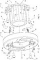
- Fig. 1 3 shows a first exemplary embodiment of the additional wheel weight according to the invention for an agricultural utility vehicle, reproduced in an exploded view, the additional wheel weight according to the invention below with reference to the two cross-sectional views in FIG Fig. 2 or 3 is described.
- the additional wheel weight 10 has a weight disk 12 and a holder 16 that can be attached to a wheel rim 14 for fastening the weight disk 12.
- the weight plate 12 comprises a manually operable first and second locking mechanism 18, each of which has an axially extending guide opening 20 for receiving a coupling element 22 assigned to the holder in the form of an exchangeable coupling ball 24 and a releasable locking element 26 for locking the coupling ball 24 within the guide opening 20 .
- the first and second locking mechanism 18 are arranged in radially opposite positions of the weight disk 12.
- FIG. Fig. 2 or 3 The design of the guide opening 20 is shown in FIG Fig. 2 or 3, which tapers conically inwards in order to simplify the centering of the coupling ball 24 with respect to the guide opening 20 when the weight disk 12 is mounted on the holder 16.
- the bracket 16 has a hollow cylindrical base body 28 and a circumferential fastening flange 30 for attachment to the wheel rim 14, the fastening flange 30 being designed as a screw ring 32 for fastening to a counter flange 34 of the wheel rim 14.
- the fastening takes place here by means of associated screw bolts 36.
- axially extending sliding ribs 38 are formed on the holder 16 along the hollow cylindrical base body 28.
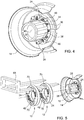
- the hollow cylindrical base body 28, when mounted on the wheel rim 14, also serves to provide mechanical protection for an in Fig. 4 illustrated wheel drive housing 40.
- the wheel drive housing 40 houses a reduction gear, as it is provided on the front wheels of all-wheel drive agricultural tractors.
- use of the additional wheel weight 10 is not restricted to agricultural tractors, but can also be used in any other agricultural utility vehicles, such as harvesting machines or forage harvesters.
- the weight disk 12 has a central recess 42 for the form-fitting reception of the holder 16, more precisely the hollow-cylindrical base body 28 encompassed by it.
- the additional wheel weight 10 is installed by axially sliding the weight disk 12 onto the bracket 16 or the hollow cylindrical base body 28 encompassed by it.
- the guide openings 20 are thereby aligned with the coupling balls 24 of the bracket by rotating the weight disk 12 16 positioned so that they can be brought into engagement with one another by being pushed on and locked by means of the locking mechanism 18.
- the holder 16 In order to relieve the locking mechanism 18 of torsional forces acting on the weight plate 12 due to travel, the holder 16 has a plurality of projections 46 which positively engage in corresponding receiving openings 44. Such torsional forces occur in particular when braking or accelerating due to changing wheel speeds of the agricultural utility vehicle.
- the locking element 26 is a locking bolt 50 displaceable within a bore 48, with a locking contour 54 being formed on the locking bolt 50 in an end region 52 facing the guide opening 20, which has a spherical shape corresponding to the spherical surface.
- the spherical locking contour 54 forms a contact surface for the coupling ball 24 located in the guide opening 20, the contact surface at least partially engages or engages behind the coupling ball 24 in the expansion direction 56, provided that the locking bolt 50 is in the in Fig. 3 locking position shown.
- the locking bolt 50 can be moved from the locking position into an unlocking position releasing the coupling ball 24 by means of an actuating lever 64 articulated via associated fastening pins 60, 62 counter to the action of a return spring 58.
- a return spring 58 is in Fig. 2 shown.
- the spring constant of the return spring 58 is dimensioned or selected in such a way that, in addition to maintaining a reliable securing effect, it is possible to pivot the actuating lever 64 by hand without problems, namely without tools.
- the actuating lever 64 in the locking position is received essentially flush in a recess 66 encompassed by the weight disk 12, the actuating lever 64 being able to be folded out of the recess 66 by hand to release the coupling ball 24.
- the locking bolt 50 together with the return spring 58, forms a snap lock that can be released by means of the actuating lever 64 for the automatic locking of the coupling ball 24.
- the locking bolt 50 is moved or pushed away when the weight disc 12 is pushed on by the coupling ball 24, releasing the guide opening 20 until this your in Fig. 2 assumes reproduced end position within the guide opening 20 and the locking bolt 50 by itself in the locking position according to Fig. 3 able to return in order to secure the coupling ball 24.
- Fig. 5 the additional wheel weight 10 is shown during the assembly of several weight disks 12 with the aid of a loading fork 68, for which purpose the weight disks 12 in turn have coupling balls 24 for attaching additional weight disks.
- the two weight disks 12 have recesses 70 for receiving the loading fork 68 or a cable pull (not shown) educated.
- the loading fork 68 is part of a front loader of an agricultural tractor (not shown). In this case, the weight disks 12 are raised until the central recesses 42 provided in the weight disks 12 are aligned with the holder 16 and thus allow a problem-free pushing on.
- the dismantling of the weight disks 12 takes place in reverse order and can also be carried out with the aid of a front loader after releasing the respectively associated locking mechanism 18.
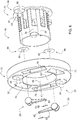
- Fig. 6 shows a second exemplary embodiment of the additional wheel weight according to the invention for an agricultural utility vehicle, reproduced in an exploded view, the additional wheel weight according to the invention below with reference to the two cross-sectional views in FIG Fig. 7 or 8 is described.
- the second exemplary embodiment differs from the first exemplary embodiment with regard to the design of the locking mechanism 18.
- the spherically running locking contour 54 is formed directly on a pivotably mounted actuating lever 72.
- the locking contour 54 is oriented around a pivot axis 74 which is aligned with the center point of the coupling ball 24 located in the guide opening 20, which is the case when the coupling ball 24 is in the position shown in FIG Fig. 7 or 8 shown end position.
- the spherical locking contour 54 extends eccentrically with respect to the pivot axis 74 of the actuating lever 72 that the coupling ball 24 is in the position shown in FIG Fig. 8 or 10 reproduced locking position within the guide opening 20 can be braced.
- a securing element 76 for releasably fixing the actuating lever 72 in the locking position.
- the securing element 76 has a securing lug 78 formed on the weight disk 12, which extends through an opening 80 formed in the actuating lever 72 in the event that it is in its locking position Fig. 8 or 10 is located.
- a split pin 82 can be inserted through the securing lug 78 in such a way that pivoting out of the locking position is blocked.
- a tensioning element 84 is used to produce a frictional connection between the holder 16 and the weight disk 12.
- the tensioning element 84 is designed in the form of a plate spring 86 arranged between the holder 16 and the weight disk 12.
- the plate spring 86 is slipped onto a fastening base 88 formed on the coupling ball 24.
- the plate spring 86 is compressed relative to the holder 16, so that undesired travel-related movements between the weight plate 12 and the holder 16 are damped.
- the locking mechanism 18 is operated in principle as in the case of the first exemplary embodiment.
Landscapes
- Engineering & Computer Science (AREA)
- Mechanical Engineering (AREA)
- Chemical & Material Sciences (AREA)
- Combustion & Propulsion (AREA)
- Transportation (AREA)
- General Engineering & Computer Science (AREA)
- Agricultural Machines (AREA)
- Steering-Linkage Mechanisms And Four-Wheel Steering (AREA)
- Harvester Elements (AREA)
Description
- Die Erfindung betrifft ein Radzusatzgewicht für ein landwirtschaftliches Nutzfahrzeug, mit einer Gewichtsscheibe und einer an einer Radfelge anbringbaren Halterung zur Befestigung der Gewichtsscheibe.
- Ein derartiges Radzusatzgewicht zur Ballastierung einer Antriebsachse eines landwirtschaftlichen Traktors ist beispielsweise aus der
US2005/280308A1 oder aus derDE 10 2014 202 074 A1 bekannt. Das Radzusatzgewicht umfasst eine an einer Radfelge mittels eines Schraubkranzes befestigbare Adapterplatte sowie eine an der Adapterplatte anbringbare Gewichtsscheibe. Um die korrekte Positionierung der Gewichtsscheibe zu vereinfachen, sind mehrere ineinandergreifende konische Anlageflächen bzw. Codierungsausformungen und Distanzdome vorgesehen. Die endgültige Montage erfolgt hierbei mittels herkömmlicher Schraubbolzen. - Es ist Aufgabe der vorliegenden Erfindung, ein Radzusatzgewicht der eingangs genannten Art hinsichtlich seiner Handhabung während der Montage weiter zu verbessern.
- Diese Aufgabe wird durch ein Radzusatzgewicht für ein landwirtschaftliches Nutzfahrzeug mit den Merkmalen des Patentanspruchs 1 gelöst.
- Das Radzusatzgewicht für ein landwirtschaftliches Nutzfahrzeug weist eine Gewichtsscheibe und eine an einer Radfelge anbringbare Halterung zur Befestigung der Gewichtsscheibe auf. Die Gewichtsscheibe umfasst einen von Hand und/oder durch Fremdkraft betätigbaren Verschlussmechanismus, der eine axial verlaufende Führungsöffnung zur Aufnahme eines der Halterung zugeordneten Kupplungselements sowie ein lösbares Verriegelungselement zur Arretierung des Kupplungselements innerhalb der Führungsöffnung aufweist. Eine Fremdkraftbetätigung des Verschlussmechanismus kann hierbei mittels eines elektromotorischen Antriebs oder dergleichen erfolgen.
- Da sich die meist mehrere 100 kg schwere Gewichtsscheibe beim Montieren bzw. Aufschieben an dem innerhalb der Führungsöffnung axial geführten Kupplungselement abstützen kann und darin mittels des Verriegelungselements zugleich arretierbar ist, ist eine besonders sichere und komfortable Anbringung des Radzusatzgewichts möglich. Im Falle eines als landwirtschaftlicher Traktor ausgebildeten landwirtschaftlichen Nutzfahrzeugs können entsprechende Radzusatzgewichte sowohl an den Vorder- als auch Hinterrädern, im Falle einer Erntemaschine oder eines Feldhäckslers ausschließlich an den Hinterrädern vorgesehen sein, wobei einer Anbringung an den Vorderrädern ebenfalls nichts entgegensteht.
- Unter der axialen Ausrichtung der Führungsöffnung ist hierbei diejenige Richtung zu verstehen, die mit dem jeweiligen Achsverlauf der mit dem Radzusatzgewicht auszustattenden bzw. ausgestatteten Radfelge korrespondiert.
- Weitere vorteilhafte Weiterbildungen des erfindungsgemäßen Radzusatzgewichts gehen aus den Unteransprüchen hervor.
- Bevorzugt weist das Verriegelungselement zur Arretierung des Kupplungselements in einer Verriegelungsposition eine in die Führungsöffnung hineinragende Sperrkontur auf. Idealerweise bildet die Sperrkontur eine Anlagefläche für das in der Führungsöffnung befindliche Kupplungselement, wobei die Anlagefläche das Kupplungselement in Ausbaurichtung zumindest teilweise umgreift bzw. hintergreift, wenn sich das Verriegelungselement in der Verriegelungsposition befindet. Bei dem Kupplungselement handelt es sich beispielsweise um eine Kupplungskugel, wobei die Sperrkontur einen mit der Kugeloberfläche korrespondierenden sphärischen Verlauf aufweist. Denkbar sind jedoch auch andere Sperrkonturen, die sich zum Arretieren eines von dem Kupplungselement umfassten pilzförmigen Kupplungskopfs oder dergleichen eignen.
- Gemäß einer ersten Ausführungsform des Radzusatzgewichts kann die Sperrkontur an einem verschiebbaren Verriegelungsbolzen bzw. einer Sperrklinke ausgebildet sein, wobei der Verriegelungsbolzen bzw. die Sperrklinke unter der Wirkung einer Rückstellfeder in die Verriegelungsposition gedrängt wird. Hierdurch ist ein selbstsichernder Verschlussmechanismus gebildet, der ein unerwünschtes Lösen aufgrund fahrtbedingter Vibrationen oder dergleichen verlässlich ausschließt.
- Insbesondere kann vorgesehen sein, dass sich der Verriegelungsbolzen bzw. die Sperrklinke entgegen der Wirkung der Rückstellfeder mittels eines Betätigungshebels in eine das Kupplungselement freigebende Entriegelungsposition verbringen lässt. Die Federkonstante der Rückstellfeder ist derart bemessen bzw. gewählt, dass neben der Aufrechterhaltung einer verlässlichen Sicherungswirkung ein problemloses, nämlich werkzeugloses Verschwenken des Betätigungshebels von Hand möglich ist.
- Darüber hinaus besteht die Möglichkeit, dass der Verriegelungsbolzen bzw. die Sperrklinke gemeinsam mit der Rückstellfeder einen mittels des Betätigungshebels lösbaren Schnappverschluss zur selbsttätigen Arretierung des Kupplungselements bilden. In diesem Fall wird der Verriegelungsbolzen bzw. die Sperrklinke beim Aufschieben der Gewichtsscheibe seitens des Kupplungselements unter Freigabe der Führungsöffnung solange mitverschoben bzw. weggeschoben, bis diese ihre Endlage innerhalb der Führungsöffnung einnimmt und der Verriegelungsbolzen bzw. die Sperrklinke von selbst in die Verriegelungsposition zurückzukehren vermag, um das Kupplungselement zu sichern. Der Schnappverschluss stellt einen zusätzlichen Komfortgewinn für den Bediener dar, da zur Montage der Gewichtsscheibe keine zusätzlichen Handgriffe erforderlich sind, die Gewichtsscheibe insbesondere nicht in unmontiertem Zustand losgelassen werden muss, um separate Sicherungselemente wie Schraubbolzen oder dergleichen anzubringen.
- Gemäß einer zweiten Ausführungsform des Radzusatzgewichts kann die Sperrkontur an einem schwenkbar gelagerten Betätigungshebel ausgeformt sein. Insbesondere kann in diesem Fall das Kupplungselement als Kupplungskugel ausgebildet sein, wobei die Sperrkontur einen sphärischen Verlauf aufweist, der um eine mit dem Mittelpunkt der in der Führungsöffnung befindlichen Kupplungskugel fluchtende Schwenkachse orientiert ist.
- Dabei besteht die Möglichkeit, dass die sphärische Sperrkontur bezüglich der Schwenkachse des Betätigungshebels derart exzentrisch verläuft, dass die Kupplungskugel in der Verriegelungsposition innerhalb der Führungsöffnung verspannt ist, sodass sich ein toleranzbedingtes Spiel zwischen Kupplungskugel und Führungsöffnung ausgleichen lässt.
- Zusätzlich oder alternativ kann ein Sicherungselement zur lösbaren Fixierung des Betätigungshebels in der Verriegelungsposition vorhanden sein. Das Sicherungselement kann eine an der Gewichtsscheibe ausgebildete Sicherungsnase aufweisen, die sich durch eine in dem Betätigungshebel ausgebildete Öffnung für den Fall hindurcherstreckt, dass sich dieser in seiner Verriegelungsposition befindet. Zur Sicherung des Betätigungshebels ist durch die Sicherungsnase ein Splint derart hindurchsteckbar, dass ein Verschwenken aus der Verriegelungsposition blockiert wird.
- Um ein ungewolltes Lösen des Verriegelungsmechanismus zu erschweren, ist es denkbar, dass der Betätigungshebel in der Verriegelungsposition im Wesentlichen flächenbündig in einer von der Gewichtsscheibe umfassten Ausnehmung aufgenommen ist, wobei sich der Betätigungshebel zur Freigabe der Kupplungskugel von Hand aus der Ausnehmung herausklappen lässt, ein unbeabsichtigtes Herausklappen aufgrund vorbeistreifenden Gestrüpps oder dergleichen hingegen weitgehend ausgeschlossen ist.
- Des Weiteren ist es möglich, dass ein Spannelement zur Herstellung eines Kraftschlusses zwischen der Halterung und der Gewichtsscheibe vorgesehen ist. Das Spannelement kann in Gestalt einer zwischen der Halterung und der Gewichtsscheibe angeordneten Tellerfeder ausgebildet sein. Die Tellerfeder ist beispielsweise auf eine an der Kupplungskugel ausgebildete Befestigungsbasis aufgesteckt. Beim Aufschieben der Gewichtsscheibe wird die Tellerfeder gegenüber der Halterung komprimiert, sodass unerwünschte fahrtbedingte Bewegungen zwischen Gewichtsscheibe und Halterung gedämpft werden.
- Bevorzugt weist die Gewichtsscheibe mehrere Verschlussmechanismen in radial gegenüberliegenden Positionen auf, sodass eine sichere Befestigung der Gewichtsscheibe an der Halterung gewährleistet ist. Hierbei ist es von Vorteil, wenn genau zwei Verschlussmechanismen vorgesehen sind, da in diesem Fall eine einzelne Person in der Lage ist, diese mit beiden Händen gleichzeitig zu bedienen bzw. zu betätigen.
- Um den Verschlussmechanismus von fahrtbedingt an der Gewichtsscheibe angreifenden Torsionskräften zu entlasten, kann die Halterung zudem mehrere, in entsprechende Aufnahmeöffnungen formschlüssig eingreifende Vorsprünge oder dergleichen aufweisen. Derartige Torsionskräfte treten insbesondere beim Bremsen oder Beschleunigen bedingt durch sich ändernde Raddrehzahlen des landwirtschaftlichen Nutzfahrzeugs auf.
- Es ist vorstellbar, dass die Halterung einen hohlzylindrischen Grundkörper sowie einen umlaufenden Befestigungsflansch zur Anbringung an einer Radfelge aufweist. Der hohlzylindrische Grundkörper kann in an der Radfelge montiertem Zustand zugleich dem mechanischen Schutz eines Radendantriebgehäuses dienen. Ein derartiges Radendantriebgehäuse mit einem darin beherbergten Untersetzungsgetriebe ist bei allradgetriebenen landwirtschaftlichen Traktoren an den Vorderrädern vorgesehen. Der Befestigungsflansch kann hierbei als Schraubkranz zur Befestigung an einem Gegenflansch der Radfelge ausgebildet sein.
- Ferner kann die Gewichtsscheibe eine zentrale Ausnehmung zur formschlüssigen Aufnahme der Halterung, insbesondere eines von dieser umfassten hohlzylindrischen Grundkörpers aufweisen. In diesem Fall vermag sich das gesamte Gewicht der Gewichtsscheibe radial an der Halterung abzustützen, sodass dem Auftreten von am Verschlussmechanismus wirkenden unerwünschten Scherkräften vorgebeugt wird.
- Hierbei können an der Halterung entlang des hohlzylindrischen Grundkörpers axial verlaufende Gleitrippen ausgebildet sein. Dies führt zu einer entsprechenden Verringerung der Kontaktfläche und damit der Reibung zwischen Gewichtsscheibe und Halterung, sodass sich diese beim Montieren gegenüber der Halterung leichter positionieren lässt.
- Ist eine zusätzliche Erhöhung des Gewichts gewünscht, so ist es möglich, dass die Gewichtsscheibe ihrerseits ein Kupplungselement zur Anbringung einer weiteren Gewichtsscheibe aufweist.
- Auch können an der Gewichtsscheibe im Sinne einer leichteren Handhabung Ausnehmungen zur Aufnahme einer Ladergabel oder eines Seilzugs ausgebildet sein. Hierbei wird die Gewichtsscheibe beispielsweise mittels eines an einem landwirtschaftlichen Traktor vorgesehenen Frontladers oder eines Flaschenzugs soweit angehoben, bis die in der Gewichtsscheibe vorgesehene zentrale Ausnehmung mit der Halterung fluchtet und so ein problemloses Aufschieben zulässt.
- Das erfindungsgemäße Radzusatzgewicht wird im Folgenden anhand der beigefügten Zeichnungen näher erläutert. Dabei sind hinsichtlich ihrer Funktion übereinstimmende bzw. vergleichbare Bauteile mit denselben Bezugszeichen gekennzeichnet. Es zeigen:
- Fig. 1
- ein in Explosionsdarstellung wiedergegebenes erstes Ausführungsbeispiel des erfindungsgemäßen Radzusatzgewichts, umfassend eine einzelne Gewichtsscheibe und eine an einer Radfelge anbringbare Halterung,
- Fig. 2
- eine Querschnittsdarstellung des in
Fig. 1 gezeigten Radzusatzgewichts während der Montage, - Fig. 3
- eine Querschnittsdarstellung des in
Fig. 1 gezeigten Radzusatzgewichts in montiertem Zustand, - Fig. 4
- eine perspektivische Ansicht des in
Fig. 3 gezeigten Radzusatzgewichts bei abgenommener Gewichtsscheibe, - Fig. 5
- das in
Fig. 1 gezeigte Radzusatzgewicht im Falle der Montage mehrerer Gewichtsscheiben unter Zuhilfenahme einer Ladergabel, - Fig. 6
- ein in Explosionsdarstellung wiedergegebenes zweites Ausführungsbeispiel des erfindungsgemäßen Radzusatzgewichts, umfassend eine einzelne Gewichtsscheibe und eine an einer Radfelge anbringbare Halterung,
- Fig. 7
- eine Querschnittsdarstellung des in
Fig. 6 gezeigten Radzusatzgewichts während der Montage, - Fig. 8
- eine Querschnittsdarstellung des in
Fig. 6 gezeigten Radzusatzgewichts in montiertem Zustand, - Fig. 9
- eine Querschnittsdarstellung eines von dem Radzusatzgewicht gemäß
Fig. 6 umfassten Verschlussmechanismus in einer Entriegelungsposition, und - Fig. 10
- eine Querschnittsdarstellung eines von dem Radzusatzgewicht gemäß
Fig. 6 umfassten Verschlussmechanismus in einer Verriegelungsposition. -
Fig. 1 zeigt ein in Explosionsdarstellung wiedergegebenes erstes Ausführungsbeispiel des erfindungsgemäßen Radzusatzgewichts für ein landwirtschaftliches Nutzfahrzeug, wobei das erfindungsgemäße Radzusatzgewicht nachfolgend unter Bezugnahme auf die beiden Querschnittsdarstellungen inFig. 2 bzw. 3 beschrieben wird. - Das Radzusatzgewicht 10 weist eine Gewichtsscheibe 12 und eine an einer Radfelge 14 anbringbare Halterung 16 zur Befestigung der Gewichtsscheibe 12 auf. Die Gewichtsscheibe 12 umfasst einen von Hand betätigbaren ersten und zweiten Verschlussmechanismus 18, der jeweils eine axial verlaufende Führungsöffnung 20 zur Aufnahme eines der Halterung zugeordneten Kupplungselements 22 in Gestalt einer austauschbaren Kupplungskugel 24 sowie ein lösbares Verriegelungselement 26 zur Arretierung der Kupplungskugel 24 innerhalb der Führungsöffnung 20 aufweist. Hierbei ist der erste und zweite Verschlussmechanismus 18 in radial gegenüber liegenden Positionen der Gewichtsscheibe 12 angeordnet.
- Die Ausgestaltung der Führungsöffnung 20 ist in
Fig. 2 bzw. 3 wiedergegeben, wobei diese sich einwärts konisch verjüngt, um das Zentrieren der Kupplungskugel 24 gegenüber der Führungsöffnung 20 beim Montieren der Gewichtsscheibe 12 an der Halterung 16 zu vereinfachen. - Die Halterung 16 weist einen hohlzylindrischen Grundköper 28 sowie einen umlaufenden Befestigungsflansch 30 zur Anbringung an der Radfelge 14 auf, wobei der Befestigungsflansch 30 als Schraubkranz 32 zur Befestigung an einem Gegenflansch 34 der Radfelge 14 ausgebildet ist. Die Befestigung erfolgt hierbei mittels zugehöriger Schraubbolzen 36.
- Zusätzlich sind an der Halterung 16 entlang des hohlzylindrischen Grundkörpers 28 axial verlaufende Gleitrippen 38 ausgebildet.
- Beispielsgemäß dient der hohlzylindrische Grundkörper 28 in an der Radfelge 14 montiertem Zustand zugleich dem mechanischen Schutz eines in
Fig. 4 veranschaulichten Radendantriebgehäuses 40. Das Radendantriebgehäuse 40 beherbergt ein Untersetzungsgetriebe, wie es bei allradgetriebenen landwirtschaftlichen Traktoren an den Vorderrädern vorgesehen ist. Hierbei sei der Vollständigkeit halber angemerkt, dass eine Verwendung des Radzusatzgewichts 10 nicht auf landwirtschaftliche Traktoren beschränkt ist, sondern auch bei beliebigen anderen landwirtschaftlichen Nutzfahrzeugen, wie Erntemaschinen oder Feldhäckslern eingesetzt werden kann. - Weiterhin weist die Gewichtsscheibe 12 eine zentrale Ausnehmung 42 zur formschlüssigen Aufnahme der Halterung 16, genauer gesagt des von dieser umfassten hohlzylindrischen Grundkörpers 28 auf.
- Die Montage des Radzusatzgewichts 10 erfolgt durch axiales Aufschieben der Gewichtsscheibe 12 auf die Halterung 16 bzw. des von dieser umfassten hohlzylindrischen Grundkörpers 28. Hierbei werden die Führungsöffnungen 20 durch Drehen der Gewichtsscheibe 12 derart fluchtend gegenüber den Kupplungskugeln 24 der Halterung 16 positioniert, dass sich diese durch weiteres Aufschieben miteinander in Eingriff bringen sowie mittels des Verriegelungsmechanismus 18 arretieren lassen.
- Zur Entlastung des Verschlussmechanismus 18 von an der Gewichtsscheibe 12 fahrtbedingt angreifenden Torsionskräften weist die Halterung 16 mehrere, in entsprechende Aufnahmeöffnungen 44 formschlüssig eingreifende Vorsprünge 46 auf. Derartige Torsionskräfte treten insbesondere beim Bremsen oder Beschleunigen bedingt durch sich ändernde Raddrehzahlen des landwirtschaftlichen Nutzfahrzeugs auf.
- Im vorliegenden Fall handelt es sich bei dem Verriegelungselement 26 um einen innerhalb einer Bohrung 48 verschiebbaren Verriegelungsbolzen 50, wobei an dem Verriegelungsbolzen 50 in einem der Führungsöffnung 20 zugewandten Endbereich 52 eine Sperrkontur 54 ausgebildet ist, die einen mit der Kugeloberfläche korrespondierenden sphärischen Verlauf aufweist.
- Wie sich
Fig. 3 entnehmen lässt, bildet die sphärisch verlaufende Sperrkontur 54 eine Anlagefläche für die in der Führungsöffnung 20 befindliche Kupplungskugel 24, wobei die Anlagefläche die Kupplungskugel 24 in Ausbaurichtung 56 zumindest teilweise umgreift bzw. hintergreift, sofern sich der Verriegelungsbolzen 50 in der inFig. 3 dargestellten Verriegelungsposition befindet. - Hierbei ist vorgesehen, dass sich der Verriegelungsbolzen 50 entgegen der Wirkung einer Rückstellfeder 58 mittels eines über zugehörige Befestigungsstifte 60, 62 angelenkten Betätigungshebels 64 aus der Verriegelungsposition in eine die Kupplungskugel 24 freigebende Entriegelungsposition verbringen lässt. Letztere ist in
Fig. 2 dargestellt. Die Federkonstante der Rückstellfeder 58 ist derart bemessen bzw. gewählt, dass neben der Aufrechterhaltung einer verlässlichen Sicherungswirkung ein problemloses, nämlich werkzeugloses Verschwenken des Betätigungshebels 64 von Hand möglich ist. - Um ein ungewolltes Lösen des Verriegelungsmechanismus 18 zu erschweren, ist der Betätigungshebel 64 in der Verriegelungsposition im Wesentlichen flächenbündig in einer von der Gewichtsscheibe 12 umfassten Ausnehmung 66 aufgenommen, wobei sich der Betätigungshebel 64 zur Freigabe der Kupplungskugel 24 von Hand aus der Ausnehmung 66 herausklappen lässt.
- Der Verriegelungsbolzen 50 bildet jeweils gemeinsam mit der Rückstellfeder 58 einen mittels des Betätigungshebels 64 lösbaren Schnappverschluss zur selbsttätigten Arretierung der Kupplungskugel 24. In diesem Fall wird der Verriegelungsbolzen 50 beim Aufschieben der Gewichtsscheibe 12 seitens der Kupplungskugel 24 unter Freigabe der Führungsöffnung 20 solange mitverschoben bzw. weggeschoben, bis diese ihre in
Fig. 2 wiedergegebene Endlage innerhalb der Führungsöffnung 20 einnimmt und der Verriegelungsbolzen 50 von selbst in die Verriegelungsposition gemäßFig. 3 zurückzukehren vermag, um die Kupplungskugel 24 zu sichern. - In
Fig. 5 ist das Radzusatzgewicht 10 bei der Montage mehrerer Gewichtsscheiben 12 unter Zuhilfenahme einer Ladergabel 68 gezeigt, wozu die Gewichtsscheiben 12 ihrerseits Kupplungskugeln 24 zur Anbringung weiterer Gewichtsscheiben aufweisen. - An den beiden Gewichtsscheiben 12 sind Ausnehmungen 70 zur Aufnahme der Ladergabel 68 oder eines nicht dargestellten Seilzugs ausgebildet. Die Ladergabel 68 ist Bestandteil eines Frontladers eines landwirtschaftlichen Traktors (nicht gezeigt). Hierbei werden die Gewichtsscheiben 12 soweit angehoben, bis die in den Gewichtsscheiben 12 vorgesehenen zentralen Ausnehmungen 42 mit der Halterung 16 fluchten und so ein problemloses Aufschieben zulassen.
- Die Demontage der Gewichtsscheiben 12 erfolgt in umgekehrter Reihenfolge und kann ebenfalls unter Zuhilfenahme eines Frontladers nach Lösen des jeweils zugehörigen Verriegelungsmechanismus 18 durchgeführt werden.
-
Fig. 6 zeigt ein in Explosionsdarstellung wiedergegebenes zweites Ausführungsbeispiel des erfindungsgemäßen Radzusatzgewichts für ein landwirtschaftliches Nutzfahrzeug, wobei das erfindungsgemäße Radzusatzgewicht nachfolgend unter Bezugnahme auf die beiden Querschnittsdarstellungen inFig. 7 bzw. 8 beschrieben wird. - Das zweite Ausführungsbeispiel unterscheidet sich von dem ersten Ausführungsbeispiel hinsichtlich der Ausgestaltung des Verschlussmechanismus 18. Bei dem insofern vorgesehenen Verriegelungselement 26 ist die sphärisch verlaufende Sperrkontur 54 unmittelbar an einem schwenkbar gelagerten Betätigungshebel 72 ausgeformt. Die Sperrkontur 54 ist um eine mit dem Mittelpunkt der in der Führungsöffnung 20 befindlichen Kupplungskugel 24 fluchtende Schwenkachse 74 orientiert, was der Fall ist, wenn sich die Kupplungskugel 24 in der in
Fig. 7 bzw. 8 dargestellten Endlage befindet. - Hierbei sind aus
Fig. 9 und 10 weitere im Querschnitt dargestellte Details hinsichtlich des Zusammenwirkens zwischen dem Betätigungshebel 72 bzw. der daran ausgebildeten Sperrkontur 54 einerseits und der Kupplungskugel 24 andererseits ersichtlich. Demgemäß folgt die Sperrkontur 54 dem sphärischen Verlauf der Kugeloberfläche und lässt sich entlang dieser um 90 Grad zwischen einer Entriegelungsposition gemäßFig. 9 und einer Verriegelungsposition gemäßFig. 10 hin- und herschwenken. Auch hier bildet die sphärisch verlaufende Sperrkontur 54 eine Anlagefläche für die in der Führungsöffnung 20 befindliche Kupplungskugel 24, wobei die Anlagefläche die Kupplungskugel 24 in Ausbaurichtung 56 zumindest teilweise umgreift bzw. hintergreift, sofern sich der Betätigungshebel 72 in der inFig. 10 dargestellten Verriegelungsposition befindet. - Optional verläuft die sphärische Sperrkontur 54 bezüglich der Schwenkachse 74 des Betätigungshebels 72 derart exzentrisch, dass die Kupplungskugel 24 in der in
Fig. 8 bzw. 10 wiedergegebenen Verriegelungsposition innerhalb der Führungsöffnung 20 verspannbar ist. - Daneben ist ein Sicherungselement 76 zur lösbaren Fixierung des Betätigungshebels 72 in der Verriegelungsposition vorhanden. Das Sicherungselement 76 weist eine an der Gewichtsscheibe 12 ausgebildete Sicherungsnase 78 auf, die sich durch eine in dem Betätigungshebel 72 ausgebildete Öffnung 80 für den Fall hindurcherstreckt, dass sich dieser in seiner Verriegelungsposition gemäß
Fig. 8 bzw. 10 befindet. Zur Sicherung des Betätigungshebels 72 ist durch die Sicherungsnase 78 ein Splint 82 derart hindurchsteckbar, dass ein Verschwenken aus der Verriegelungsposition blockiert wird. - Ein Spannelement 84 dient der Herstellung eines Kraftschlusses zwischen der Halterung 16 und der Gewichtsscheibe 12. Das Spannelement 84 ist in Gestalt einer zwischen der Halterung 16 und der Gewichtsscheibe 12 angeordneten Tellerfeder 86 ausgebildet. Die Tellerfeder 86 ist im vorliegenden Fall auf eine an der Kupplungskugel 24 ausgebildete Befestigungsbasis 88 aufgesteckt. Beim Aufschieben der Gewichtsscheibe 12 wird die Tellerfeder 86 gegenüber der Halterung 16 komprimiert, sodass unerwünschte fahrtbedingte Bewegungen zwischen Gewichtsscheibe 12 und Halterung 16 gedämpft werden.
- Bezüglich der Montage bzw. Demontage des Radzusatzgewichts 10 sei ergänzend auf die in
Fig. 5 dargestellte Vorgehensweise verwiesen. Die Bedienung des Verschlussmechanismus 18 erfolgt prinzipiell wie im Falle des ersten Ausführungsbeispiels.
Claims (17)
- Radzusatzgewicht für ein landwirtschaftliches Nutzfahrzeug, mit einer Gewichtsscheibe (12) und einer an einer Radfelge (14) anbringbaren Halterung (16) zur Befestigung der Gewichtsscheibe (12), wobei die Gewichtsscheibe (12) einen von Hand und/oder durch Fremdkraft betätigbaren Verschlussmechanismus (18) umfasst, der eine axial verlaufende Führungsöffnung (20) zur Aufnahme eines der Halterung (16) zugeordneten Kupplungselements (22) sowie ein lösbares Verriegelungselement (26) zur Arretierung des Kupplungselements (22) innerhalb der Führungsöffnung (20) aufweist.
- Radzusatzgewicht nach Anspruch 1, dadurch gekennzeichnet, dass das Verriegelungselement (26) zur Arretierung des Kupplungselements (22) in einer Verriegelungsposition eine in die Führungsöffnung (20) hineinragende Sperrkontur (54) aufweist.
- Radzusatzgewicht nach Anspruch 2, dadurch gekennzeichnet, dass die Sperrkontur (54) an einem verschiebbaren Verriegelungsbolzen (50) bzw. einer Sperrklinke ausgebildet ist, wobei der Verriegelungsbolzen (50) bzw. die Sperrklinke unter der Wirkung einer Rückstellfeder (58) in die Verriegelungsposition gedrängt wird.
- Radzusatzgewicht nach Anspruch 3, dadurch gekennzeichnet, dass sich der Verriegelungsbolzen (50) bzw. die Sperrklinke entgegen der Wirkung der Rückstellfeder (58) mittels eines Betätigungshebels (64) in eine das Kupplungselement (22) freigebende Entriegelungsposition verbringen lässt.
- Radzusatzgewicht nach Anspruch 3 oder 4, dadurch gekennzeichnet, dass der Verriegelungsbolzen (50) bzw. die Sperrklinke gemeinsam mit der Rückstellfeder (58) einen mittels des Betätigungshebels (64) lösbaren Schnappverschluss zur selbsttätigen Arretierung des Kupplungselements (22) bilden.
- Radzusatzgewicht nach Anspruch 2, dadurch gekennzeichnet, dass die Sperrkontur (54) an einem schwenkbar gelagerten Betätigungshebel (72) ausgeformt ist.
- Radzusatzgewicht nach Anspruch 6, dadurch gekennzeichnet, dass das Kupplungselement (22) als Kupplungskugel (24) ausgebildet ist, wobei die Sperrkontur (54) einen sphärischen Verlauf aufweist, der um eine mit dem Mittelpunkt der in der Führungsöffnung (20) befindlichen Kupplungskugel (24) fluchtende Schwenkachse (74) orientiert ist.
- Radzusatzgewicht nach Anspruch 7, dadurch gekennzeichnet, dass die sphärische Sperrkontur (54) bezüglich der Schwenkachse (74) des Betätigungshebels (72) derart exzentrisch verläuft, dass die Kupplungskugel (24) in der Verriegelungsposition innerhalb der Führungsöffnung (20) verspannt ist.
- Radzusatzgewicht nach Anspruch 4 oder 6, dadurch gekennzeichnet, dass ein Sicherungselement (76) zur lösbaren Fixierung des Betätigungshebels (64; 72) in der Verriegelungsposition vorhanden ist.
- Radzusatzgewicht nach Anspruch 4 oder 6, dadurch gekennzeichnet, dass der Betätigungshebel (64; 72) in der Verriegelungsposition im Wesentlichen flächenbündig in einer von der Gewichtsscheibe (12) umfassten Ausnehmung (66) aufgenommen ist.
- Radzusatzgewicht nach wenigstens einem der Ansprüche 1 bis 10, dadurch gekennzeichnet, dass ein Spannelement (84) zur Herstellung eines Kraftschlusses zwischen der Halterung (16) und der Gewichtsscheibe (12) vorgesehen ist.
- Radzusatzgewicht nach wenigstens einem der Ansprüche 1 bis 11, dadurch gekennzeichnet, dass die Gewichtsscheibe (12) mehrere Verschlussmechanismen (18) in radial gegenüberliegenden Positionen aufweist.
- Radzusatzgewicht nach wenigstens einem der Ansprüche 1 bis 12, dadurch gekennzeichnet, dass die Halterung (12) einen hohlzylindrischen Grundkörper (28) sowie einen umlaufenden Befestigungsflansch (30) zur Anbringung an einer Radfelge (14) aufweist.
- Radzusatzgewicht nach wenigstens einem der Ansprüche 1 bis 13, dadurch gekennzeichnet, dass die Gewichtsscheibe (12) eine zentrale Ausnehmung (42) zur formschlüssigen Aufnahme der Halterung (16), insbesondere eines von dieser umfassten hohlzylindrischen Grundkörpers (28), aufweist.
- Radzusatzgewicht nach Anspruch 14, dadurch gekennzeichnet, dass an der Halterung (16) entlang des hohlzylindrischen Grundkörpers (28) axial verlaufende Gleitrippen (38) ausgebildet sind.
- Radzusatzgewicht nach wenigstens einem der vorhergehenden Ansprüche 1 bis 15, dadurch gekennzeichnet, dass die Gewichtsscheibe (12) ihrerseits ein Kupplungselement (22) zur Anbringung einer weiteren Gewichtsscheibe (12) aufweist.
- Radzusatzgewicht nach wenigstens einem der vorhergehenden Ansprüche 1 bis 16, dadurch gekennzeichnet, dass an der Gewichtsscheibe (12) Ausnehmungen (70) zur Aufnahme einer Ladergabel (68) oder eines Seilzugs ausgebildet sind.
Applications Claiming Priority (1)
| Application Number | Priority Date | Filing Date | Title |
|---|---|---|---|
| DE102017205465.4A DE102017205465A1 (de) | 2017-03-30 | 2017-03-30 | Radzusatzgewicht für ein landwirtschaftliches Nutzfahrzeug |
Publications (2)
| Publication Number | Publication Date |
|---|---|
| EP3385085A1 EP3385085A1 (de) | 2018-10-10 |
| EP3385085B1 true EP3385085B1 (de) | 2020-12-09 |
Family
ID=61750019
Family Applications (1)
| Application Number | Title | Priority Date | Filing Date |
|---|---|---|---|
| EP18163289.4A Active EP3385085B1 (de) | 2017-03-30 | 2018-03-22 | Radzusatzgewicht für ein landwirtschaftliches nutzfahrzeug |
Country Status (3)
| Country | Link |
|---|---|
| US (1) | US10807410B2 (de) |
| EP (1) | EP3385085B1 (de) |
| DE (1) | DE102017205465A1 (de) |
Families Citing this family (9)
| Publication number | Priority date | Publication date | Assignee | Title |
|---|---|---|---|---|
| DE102017209308A1 (de) | 2017-06-01 | 2018-12-06 | Deere & Company | Radzusatzgewicht für ein Nutzfahrzeug |
| US11724207B2 (en) * | 2019-02-26 | 2023-08-15 | Flambeau, Inc. | Adjustable counterweight for a rotatable performance device |
| US11364740B2 (en) | 2019-08-22 | 2022-06-21 | Deere & Company | Wheel weight assembly and attachment method |
| FR3102950B1 (fr) * | 2019-11-07 | 2022-03-04 | Easymass | Procede et dispositif de fixation de masses d’alourdissement sur une roue d’engin agricole |
| US11427989B2 (en) * | 2019-11-14 | 2022-08-30 | Caterpillar Inc. | Retainer sleeve design with external ribs |
| WO2023084326A1 (en) * | 2021-11-10 | 2023-05-19 | Agco International Gmbh | A wheel weight handling device and a method of using the wheel weight handling device |
| FR3150464B1 (fr) * | 2023-06-30 | 2025-07-18 | Easymass | Procede et dispositif de lestage d’une roue d’engin agricole avec systeme de securite integree |
| GB202311948D0 (en) * | 2023-08-03 | 2023-09-20 | Agco Int Gmbh | Weighting a vehicle |
| US12311696B1 (en) | 2023-11-03 | 2025-05-27 | Cnh Industrial America Llc | Wheel weight system for an agricultural vehicle |
Family Cites Families (12)
| Publication number | Priority date | Publication date | Assignee | Title |
|---|---|---|---|---|
| US2859065A (en) * | 1957-04-29 | 1958-11-04 | Hermond O Darby | Wheel weights for tractors |
| US2988401A (en) * | 1959-02-13 | 1961-06-13 | Kenneth O Matz | Weight for vehicle wheel |
| DE1279496B (de) * | 1964-06-19 | 1968-10-03 | Internat Harvester Co M B H | Zusatzgewicht zur Befestigung an der Radscheibe von Fahrzeugraedern, insbesondere Treibraedern landwirtschaftlich genutzter Motorfahrzeuge |
| US3644002A (en) * | 1969-08-20 | 1972-02-22 | Deere & Co | Wheel weight assembly for a tractor |
| JPS5849436B2 (ja) * | 1980-08-06 | 1983-11-04 | マエダ工業株式会社 | 自転車用クイツクレリ−ズハブ |
| US5873636A (en) * | 1996-03-04 | 1999-02-23 | Dayton Walther Corporation | Balance weight retention system for vehicle wheel or hub |
| US6283556B1 (en) * | 1999-11-16 | 2001-09-04 | F .B. T. Enterprises, Inc. | Reversible wheel weight for counterbalancing industrial and agricultural vehicles |
| US7182409B2 (en) * | 2004-06-21 | 2007-02-27 | Sop Services, Inc. | Quick fastening wheel weight system |
| US8944521B2 (en) * | 2012-06-22 | 2015-02-03 | Deere & Company | Wheel weight assembly |
| DE102014202074A1 (de) | 2014-02-05 | 2015-08-06 | Deere & Company | Radzusatzgewicht |
| DE102017209308A1 (de) * | 2017-06-01 | 2018-12-06 | Deere & Company | Radzusatzgewicht für ein Nutzfahrzeug |
| US10457092B2 (en) * | 2017-09-22 | 2019-10-29 | Deere & Company One John Deere Place | Wheel weight assembly |
-
2017
- 2017-03-30 DE DE102017205465.4A patent/DE102017205465A1/de not_active Withdrawn
-
2018
- 2018-03-22 EP EP18163289.4A patent/EP3385085B1/de active Active
- 2018-03-28 US US15/938,430 patent/US10807410B2/en active Active
Also Published As
| Publication number | Publication date |
|---|---|
| EP3385085A1 (de) | 2018-10-10 |
| US10807410B2 (en) | 2020-10-20 |
| US20180281512A1 (en) | 2018-10-04 |
| DE102017205465A1 (de) | 2018-10-04 |
Similar Documents
| Publication | Publication Date | Title |
|---|---|---|
| EP3385085A1 (de) | Radzusatzgewicht für ein landwirtschaftliches nutzfahrzeug | |
| DE69703178T2 (de) | Axial (ent)kuppelndes Schloss für ein Schlossmechanismus eines Personenkraftwagens | |
| DE69215689T2 (de) | Verriegelungsvorrichtung eines kippbaren fahrerhauses | |
| EP3409502A1 (de) | Radzusatzgewicht für ein nutzfahrzeug | |
| DE102021123507A1 (de) | Im Lenkradkranz integrierter Kippmechanismus | |
| EP0568921B1 (de) | Kupplungseinrichtung | |
| EP3803006B1 (de) | Türgriffanordnung für ein kraftfahrzeug | |
| EP2036421B1 (de) | Vorrichtung zum Kuppeln einer Gelenkwelle mit einer Zapfwelle eines Traktors | |
| DE602005003743T2 (de) | Lenksperre | |
| DE69907311T2 (de) | Axial entkuppelndes Schloss für ein Schlossmechanismus eines Personenkraftwagens | |
| EP1679202A1 (de) | Diebstahlschutzeinrichtung für Räder, insbesondere für Leichtmetallräder von Kraftfahrzeugen | |
| DE102018129157A1 (de) | Bremsanordnung für ein Laufrad eines Rollstuhls, Laufrad und Rollstuhl | |
| EP2467611A1 (de) | Radial wirkende rotationsarretierung | |
| DE3826932C2 (de) | ||
| DE2916011C3 (de) | Verriegelungssystem für zwei auf einer gemeinsamen Welle angeordnete Bremspedala eines Kraftfahrzeuges | |
| DE102022128939B4 (de) | Trennmechanismen, getriebesysteme, die diese enthalten, und zugehörige verfahren | |
| EP4052932B1 (de) | Zubehöradapter zur befestigung von kraftfahrzeugzubehör an einer radnabe mit zentralgewinde | |
| EP0904223A1 (de) | Einstellvorrichtung mit selbsttätigem längenausgleich für einen betätigungszug | |
| EP1293693B1 (de) | Sicherheitskupplungsanordnung in einem Antrieb für Landmaschinen | |
| DE102020209170B4 (de) | Radgewichtsbaugruppe | |
| EP1700759B1 (de) | Sicherungseinrichtung und Sicherungsverfahren für Fahrzeuganhänger | |
| DE19916422B4 (de) | Vorrichtung zur lösbaren Befestigung eines Fahrzeugsitzes am Fahrzeugboden | |
| DE3540641A1 (de) | Anhaengerkupplung - stichwort: "kupplungsmaulzentrierung am automatikgehaeuse" | |
| EP1717067B1 (de) | Antrieb für eine Anhängerkupplung | |
| DE69705299T2 (de) | Diebstahlsicherung für ein kraftfahrzeug |
Legal Events
| Date | Code | Title | Description |
|---|---|---|---|
| PUAI | Public reference made under article 153(3) epc to a published international application that has entered the european phase |
Free format text: ORIGINAL CODE: 0009012 |
|
| STAA | Information on the status of an ep patent application or granted ep patent |
Free format text: STATUS: THE APPLICATION HAS BEEN PUBLISHED |
|
| AK | Designated contracting states |
Kind code of ref document: A1 Designated state(s): AL AT BE BG CH CY CZ DE DK EE ES FI FR GB GR HR HU IE IS IT LI LT LU LV MC MK MT NL NO PL PT RO RS SE SI SK SM TR |
|
| AX | Request for extension of the european patent |
Extension state: BA ME |
|
| STAA | Information on the status of an ep patent application or granted ep patent |
Free format text: STATUS: REQUEST FOR EXAMINATION WAS MADE |
|
| 17P | Request for examination filed |
Effective date: 20190410 |
|
| RBV | Designated contracting states (corrected) |
Designated state(s): AL AT BE BG CH CY CZ DE DK EE ES FI FR GB GR HR HU IE IS IT LI LT LU LV MC MK MT NL NO PL PT RO RS SE SI SK SM TR |
|
| GRAP | Despatch of communication of intention to grant a patent |
Free format text: ORIGINAL CODE: EPIDOSNIGR1 |
|
| STAA | Information on the status of an ep patent application or granted ep patent |
Free format text: STATUS: GRANT OF PATENT IS INTENDED |
|
| INTG | Intention to grant announced |
Effective date: 20200710 |
|
| GRAS | Grant fee paid |
Free format text: ORIGINAL CODE: EPIDOSNIGR3 |
|
| GRAA | (expected) grant |
Free format text: ORIGINAL CODE: 0009210 |
|
| STAA | Information on the status of an ep patent application or granted ep patent |
Free format text: STATUS: THE PATENT HAS BEEN GRANTED |
|
| AK | Designated contracting states |
Kind code of ref document: B1 Designated state(s): AL AT BE BG CH CY CZ DE DK EE ES FI FR GB GR HR HU IE IS IT LI LT LU LV MC MK MT NL NO PL PT RO RS SE SI SK SM TR |
|
| REG | Reference to a national code |
Ref country code: GB Ref legal event code: FG4D Free format text: NOT ENGLISH |
|
| REG | Reference to a national code |
Ref country code: AT Ref legal event code: REF Ref document number: 1343041 Country of ref document: AT Kind code of ref document: T Effective date: 20201215 Ref country code: CH Ref legal event code: EP |
|
| REG | Reference to a national code |
Ref country code: DE Ref legal event code: R096 Ref document number: 502018003219 Country of ref document: DE |
|
| REG | Reference to a national code |
Ref country code: IE Ref legal event code: FG4D Free format text: LANGUAGE OF EP DOCUMENT: GERMAN |
|
| PG25 | Lapsed in a contracting state [announced via postgrant information from national office to epo] |
Ref country code: RS Free format text: LAPSE BECAUSE OF FAILURE TO SUBMIT A TRANSLATION OF THE DESCRIPTION OR TO PAY THE FEE WITHIN THE PRESCRIBED TIME-LIMIT Effective date: 20201209 Ref country code: FI Free format text: LAPSE BECAUSE OF FAILURE TO SUBMIT A TRANSLATION OF THE DESCRIPTION OR TO PAY THE FEE WITHIN THE PRESCRIBED TIME-LIMIT Effective date: 20201209 Ref country code: GR Free format text: LAPSE BECAUSE OF FAILURE TO SUBMIT A TRANSLATION OF THE DESCRIPTION OR TO PAY THE FEE WITHIN THE PRESCRIBED TIME-LIMIT Effective date: 20210310 Ref country code: NO Free format text: LAPSE BECAUSE OF FAILURE TO SUBMIT A TRANSLATION OF THE DESCRIPTION OR TO PAY THE FEE WITHIN THE PRESCRIBED TIME-LIMIT Effective date: 20210309 |
|
| PG25 | Lapsed in a contracting state [announced via postgrant information from national office to epo] |
Ref country code: BG Free format text: LAPSE BECAUSE OF FAILURE TO SUBMIT A TRANSLATION OF THE DESCRIPTION OR TO PAY THE FEE WITHIN THE PRESCRIBED TIME-LIMIT Effective date: 20210309 Ref country code: LV Free format text: LAPSE BECAUSE OF FAILURE TO SUBMIT A TRANSLATION OF THE DESCRIPTION OR TO PAY THE FEE WITHIN THE PRESCRIBED TIME-LIMIT Effective date: 20201209 Ref country code: SE Free format text: LAPSE BECAUSE OF FAILURE TO SUBMIT A TRANSLATION OF THE DESCRIPTION OR TO PAY THE FEE WITHIN THE PRESCRIBED TIME-LIMIT Effective date: 20201209 |
|
| REG | Reference to a national code |
Ref country code: NL Ref legal event code: MP Effective date: 20201209 |
|
| PG25 | Lapsed in a contracting state [announced via postgrant information from national office to epo] |
Ref country code: NL Free format text: LAPSE BECAUSE OF FAILURE TO SUBMIT A TRANSLATION OF THE DESCRIPTION OR TO PAY THE FEE WITHIN THE PRESCRIBED TIME-LIMIT Effective date: 20201209 Ref country code: HR Free format text: LAPSE BECAUSE OF FAILURE TO SUBMIT A TRANSLATION OF THE DESCRIPTION OR TO PAY THE FEE WITHIN THE PRESCRIBED TIME-LIMIT Effective date: 20201209 |
|
| REG | Reference to a national code |
Ref country code: LT Ref legal event code: MG9D |
|
| PG25 | Lapsed in a contracting state [announced via postgrant information from national office to epo] |
Ref country code: RO Free format text: LAPSE BECAUSE OF FAILURE TO SUBMIT A TRANSLATION OF THE DESCRIPTION OR TO PAY THE FEE WITHIN THE PRESCRIBED TIME-LIMIT Effective date: 20201209 Ref country code: SK Free format text: LAPSE BECAUSE OF FAILURE TO SUBMIT A TRANSLATION OF THE DESCRIPTION OR TO PAY THE FEE WITHIN THE PRESCRIBED TIME-LIMIT Effective date: 20201209 Ref country code: PT Free format text: LAPSE BECAUSE OF FAILURE TO SUBMIT A TRANSLATION OF THE DESCRIPTION OR TO PAY THE FEE WITHIN THE PRESCRIBED TIME-LIMIT Effective date: 20210409 Ref country code: LT Free format text: LAPSE BECAUSE OF FAILURE TO SUBMIT A TRANSLATION OF THE DESCRIPTION OR TO PAY THE FEE WITHIN THE PRESCRIBED TIME-LIMIT Effective date: 20201209 Ref country code: CZ Free format text: LAPSE BECAUSE OF FAILURE TO SUBMIT A TRANSLATION OF THE DESCRIPTION OR TO PAY THE FEE WITHIN THE PRESCRIBED TIME-LIMIT Effective date: 20201209 Ref country code: EE Free format text: LAPSE BECAUSE OF FAILURE TO SUBMIT A TRANSLATION OF THE DESCRIPTION OR TO PAY THE FEE WITHIN THE PRESCRIBED TIME-LIMIT Effective date: 20201209 Ref country code: SM Free format text: LAPSE BECAUSE OF FAILURE TO SUBMIT A TRANSLATION OF THE DESCRIPTION OR TO PAY THE FEE WITHIN THE PRESCRIBED TIME-LIMIT Effective date: 20201209 |
|
| PG25 | Lapsed in a contracting state [announced via postgrant information from national office to epo] |
Ref country code: PL Free format text: LAPSE BECAUSE OF FAILURE TO SUBMIT A TRANSLATION OF THE DESCRIPTION OR TO PAY THE FEE WITHIN THE PRESCRIBED TIME-LIMIT Effective date: 20201209 |
|
| REG | Reference to a national code |
Ref country code: DE Ref legal event code: R097 Ref document number: 502018003219 Country of ref document: DE |
|
| PG25 | Lapsed in a contracting state [announced via postgrant information from national office to epo] |
Ref country code: IS Free format text: LAPSE BECAUSE OF FAILURE TO SUBMIT A TRANSLATION OF THE DESCRIPTION OR TO PAY THE FEE WITHIN THE PRESCRIBED TIME-LIMIT Effective date: 20210409 |
|
| PLBE | No opposition filed within time limit |
Free format text: ORIGINAL CODE: 0009261 |
|
| STAA | Information on the status of an ep patent application or granted ep patent |
Free format text: STATUS: NO OPPOSITION FILED WITHIN TIME LIMIT |
|
| PG25 | Lapsed in a contracting state [announced via postgrant information from national office to epo] |
Ref country code: AL Free format text: LAPSE BECAUSE OF FAILURE TO SUBMIT A TRANSLATION OF THE DESCRIPTION OR TO PAY THE FEE WITHIN THE PRESCRIBED TIME-LIMIT Effective date: 20201209 Ref country code: MC Free format text: LAPSE BECAUSE OF FAILURE TO SUBMIT A TRANSLATION OF THE DESCRIPTION OR TO PAY THE FEE WITHIN THE PRESCRIBED TIME-LIMIT Effective date: 20201209 |
|
| REG | Reference to a national code |
Ref country code: CH Ref legal event code: PL |
|
| 26N | No opposition filed |
Effective date: 20210910 |
|
| PG25 | Lapsed in a contracting state [announced via postgrant information from national office to epo] |
Ref country code: DK Free format text: LAPSE BECAUSE OF FAILURE TO SUBMIT A TRANSLATION OF THE DESCRIPTION OR TO PAY THE FEE WITHIN THE PRESCRIBED TIME-LIMIT Effective date: 20201209 Ref country code: SI Free format text: LAPSE BECAUSE OF FAILURE TO SUBMIT A TRANSLATION OF THE DESCRIPTION OR TO PAY THE FEE WITHIN THE PRESCRIBED TIME-LIMIT Effective date: 20201209 |
|
| REG | Reference to a national code |
Ref country code: BE Ref legal event code: MM Effective date: 20210331 |
|
| PG25 | Lapsed in a contracting state [announced via postgrant information from national office to epo] |
Ref country code: LU Free format text: LAPSE BECAUSE OF NON-PAYMENT OF DUE FEES Effective date: 20210322 Ref country code: LI Free format text: LAPSE BECAUSE OF NON-PAYMENT OF DUE FEES Effective date: 20210331 Ref country code: IE Free format text: LAPSE BECAUSE OF NON-PAYMENT OF DUE FEES Effective date: 20210322 Ref country code: CH Free format text: LAPSE BECAUSE OF NON-PAYMENT OF DUE FEES Effective date: 20210331 Ref country code: ES Free format text: LAPSE BECAUSE OF FAILURE TO SUBMIT A TRANSLATION OF THE DESCRIPTION OR TO PAY THE FEE WITHIN THE PRESCRIBED TIME-LIMIT Effective date: 20201209 |
|
| PG25 | Lapsed in a contracting state [announced via postgrant information from national office to epo] |
Ref country code: IS Free format text: LAPSE BECAUSE OF FAILURE TO SUBMIT A TRANSLATION OF THE DESCRIPTION OR TO PAY THE FEE WITHIN THE PRESCRIBED TIME-LIMIT Effective date: 20210409 |
|
| PG25 | Lapsed in a contracting state [announced via postgrant information from national office to epo] |
Ref country code: BE Free format text: LAPSE BECAUSE OF NON-PAYMENT OF DUE FEES Effective date: 20210331 |
|
| PG25 | Lapsed in a contracting state [announced via postgrant information from national office to epo] |
Ref country code: CY Free format text: LAPSE BECAUSE OF FAILURE TO SUBMIT A TRANSLATION OF THE DESCRIPTION OR TO PAY THE FEE WITHIN THE PRESCRIBED TIME-LIMIT Effective date: 20201209 |
|
| PG25 | Lapsed in a contracting state [announced via postgrant information from national office to epo] |
Ref country code: HU Free format text: LAPSE BECAUSE OF FAILURE TO SUBMIT A TRANSLATION OF THE DESCRIPTION OR TO PAY THE FEE WITHIN THE PRESCRIBED TIME-LIMIT; INVALID AB INITIO Effective date: 20180322 |
|
| PG25 | Lapsed in a contracting state [announced via postgrant information from national office to epo] |
Ref country code: MK Free format text: LAPSE BECAUSE OF FAILURE TO SUBMIT A TRANSLATION OF THE DESCRIPTION OR TO PAY THE FEE WITHIN THE PRESCRIBED TIME-LIMIT Effective date: 20201209 |
|
| REG | Reference to a national code |
Ref country code: AT Ref legal event code: MM01 Ref document number: 1343041 Country of ref document: AT Kind code of ref document: T Effective date: 20230322 |
|
| PG25 | Lapsed in a contracting state [announced via postgrant information from national office to epo] |
Ref country code: TR Free format text: LAPSE BECAUSE OF FAILURE TO SUBMIT A TRANSLATION OF THE DESCRIPTION OR TO PAY THE FEE WITHIN THE PRESCRIBED TIME-LIMIT Effective date: 20201209 |
|
| PG25 | Lapsed in a contracting state [announced via postgrant information from national office to epo] |
Ref country code: AT Free format text: LAPSE BECAUSE OF NON-PAYMENT OF DUE FEES Effective date: 20230322 |
|
| PG25 | Lapsed in a contracting state [announced via postgrant information from national office to epo] |
Ref country code: AT Free format text: LAPSE BECAUSE OF NON-PAYMENT OF DUE FEES Effective date: 20230322 |
|
| PG25 | Lapsed in a contracting state [announced via postgrant information from national office to epo] |
Ref country code: MT Free format text: LAPSE BECAUSE OF FAILURE TO SUBMIT A TRANSLATION OF THE DESCRIPTION OR TO PAY THE FEE WITHIN THE PRESCRIBED TIME-LIMIT Effective date: 20201209 |
|
| PGFP | Annual fee paid to national office [announced via postgrant information from national office to epo] |
Ref country code: GB Payment date: 20260327 Year of fee payment: 9 |
|
| PGFP | Annual fee paid to national office [announced via postgrant information from national office to epo] |
Ref country code: DE Payment date: 20260219 Year of fee payment: 9 |
|
| PGFP | Annual fee paid to national office [announced via postgrant information from national office to epo] |
Ref country code: AT Payment date: 20260410 Year of fee payment: 5 |
|
| PGFP | Annual fee paid to national office [announced via postgrant information from national office to epo] |
Ref country code: IT Payment date: 20260319 Year of fee payment: 9 |
|
| PGFP | Annual fee paid to national office [announced via postgrant information from national office to epo] |
Ref country code: FR Payment date: 20260325 Year of fee payment: 9 |