EP3385050A1 - Method of manufacturing heat sink - Google Patents
Method of manufacturing heat sink Download PDFInfo
- Publication number
- EP3385050A1 EP3385050A1 EP18156243.0A EP18156243A EP3385050A1 EP 3385050 A1 EP3385050 A1 EP 3385050A1 EP 18156243 A EP18156243 A EP 18156243A EP 3385050 A1 EP3385050 A1 EP 3385050A1
- Authority
- EP
- European Patent Office
- Prior art keywords
- base material
- heat
- resin film
- radiation resin
- die
- Prior art date
- Legal status (The legal status is an assumption and is not a legal conclusion. Google has not performed a legal analysis and makes no representation as to the accuracy of the status listed.)
- Granted
Links
Images




Classifications
-
- F—MECHANICAL ENGINEERING; LIGHTING; HEATING; WEAPONS; BLASTING
- F28—HEAT EXCHANGE IN GENERAL
- F28F—DETAILS OF HEAT-EXCHANGE AND HEAT-TRANSFER APPARATUS, OF GENERAL APPLICATION
- F28F13/00—Arrangements for modifying heat-transfer, e.g. increasing, decreasing
- F28F13/18—Arrangements for modifying heat-transfer, e.g. increasing, decreasing by applying coatings, e.g. radiation-absorbing, radiation-reflecting; by surface treatment, e.g. polishing
-
- B—PERFORMING OPERATIONS; TRANSPORTING
- B29—WORKING OF PLASTICS; WORKING OF SUBSTANCES IN A PLASTIC STATE IN GENERAL
- B29C—SHAPING OR JOINING OF PLASTICS; SHAPING OF MATERIAL IN A PLASTIC STATE, NOT OTHERWISE PROVIDED FOR; AFTER-TREATMENT OF THE SHAPED PRODUCTS, e.g. REPAIRING
- B29C63/00—Lining or sheathing, i.e. applying preformed layers or sheathings of plastics; Apparatus therefor
- B29C63/02—Lining or sheathing, i.e. applying preformed layers or sheathings of plastics; Apparatus therefor using sheet or web-like material
-
- B—PERFORMING OPERATIONS; TRANSPORTING
- B22—CASTING; POWDER METALLURGY
- B22D—CASTING OF METALS; CASTING OF OTHER SUBSTANCES BY THE SAME PROCESSES OR DEVICES
- B22D17/00—Pressure die casting or injection die casting, i.e. casting in which the metal is forced into a mould under high pressure
-
- B—PERFORMING OPERATIONS; TRANSPORTING
- B22—CASTING; POWDER METALLURGY
- B22D—CASTING OF METALS; CASTING OF OTHER SUBSTANCES BY THE SAME PROCESSES OR DEVICES
- B22D17/00—Pressure die casting or injection die casting, i.e. casting in which the metal is forced into a mould under high pressure
- B22D17/002—Pressure die casting or injection die casting, i.e. casting in which the metal is forced into a mould under high pressure using movable moulds
-
- B—PERFORMING OPERATIONS; TRANSPORTING
- B22—CASTING; POWDER METALLURGY
- B22D—CASTING OF METALS; CASTING OF OTHER SUBSTANCES BY THE SAME PROCESSES OR DEVICES
- B22D19/00—Casting in, on, or around objects which form part of the product
- B22D19/0063—Casting in, on, or around objects which form part of the product finned exchangers
-
- B—PERFORMING OPERATIONS; TRANSPORTING
- B22—CASTING; POWDER METALLURGY
- B22D—CASTING OF METALS; CASTING OF OTHER SUBSTANCES BY THE SAME PROCESSES OR DEVICES
- B22D25/00—Special casting characterised by the nature of the product
- B22D25/02—Special casting characterised by the nature of the product by its peculiarity of shape; of works of art
-
- B—PERFORMING OPERATIONS; TRANSPORTING
- B32—LAYERED PRODUCTS
- B32B—LAYERED PRODUCTS, i.e. PRODUCTS BUILT-UP OF STRATA OF FLAT OR NON-FLAT, e.g. CELLULAR OR HONEYCOMB, FORM
- B32B37/00—Methods or apparatus for laminating, e.g. by curing or by ultrasonic bonding
- B32B37/10—Methods or apparatus for laminating, e.g. by curing or by ultrasonic bonding characterised by the pressing technique, e.g. using action of vacuum or fluid pressure
-
- B—PERFORMING OPERATIONS; TRANSPORTING
- B32—LAYERED PRODUCTS
- B32B—LAYERED PRODUCTS, i.e. PRODUCTS BUILT-UP OF STRATA OF FLAT OR NON-FLAT, e.g. CELLULAR OR HONEYCOMB, FORM
- B32B37/00—Methods or apparatus for laminating, e.g. by curing or by ultrasonic bonding
- B32B37/12—Methods or apparatus for laminating, e.g. by curing or by ultrasonic bonding characterised by using adhesives
- B32B37/1284—Application of adhesive
-
- B—PERFORMING OPERATIONS; TRANSPORTING
- B29—WORKING OF PLASTICS; WORKING OF SUBSTANCES IN A PLASTIC STATE IN GENERAL
- B29L—INDEXING SCHEME ASSOCIATED WITH SUBCLASS B29C, RELATING TO PARTICULAR ARTICLES
- B29L2031/00—Other particular articles
- B29L2031/18—Heat-exchangers or parts thereof
-
- B—PERFORMING OPERATIONS; TRANSPORTING
- B32—LAYERED PRODUCTS
- B32B—LAYERED PRODUCTS, i.e. PRODUCTS BUILT-UP OF STRATA OF FLAT OR NON-FLAT, e.g. CELLULAR OR HONEYCOMB, FORM
- B32B37/00—Methods or apparatus for laminating, e.g. by curing or by ultrasonic bonding
- B32B37/12—Methods or apparatus for laminating, e.g. by curing or by ultrasonic bonding characterised by using adhesives
- B32B2037/1253—Methods or apparatus for laminating, e.g. by curing or by ultrasonic bonding characterised by using adhesives curable adhesive
-
- F—MECHANICAL ENGINEERING; LIGHTING; HEATING; WEAPONS; BLASTING
- F28—HEAT EXCHANGE IN GENERAL
- F28F—DETAILS OF HEAT-EXCHANGE AND HEAT-TRANSFER APPARATUS, OF GENERAL APPLICATION
- F28F21/00—Constructions of heat-exchange apparatus characterised by the selection of particular materials
- F28F21/08—Constructions of heat-exchange apparatus characterised by the selection of particular materials of metal
- F28F21/081—Heat exchange elements made from metals or metal alloys
- F28F21/084—Heat exchange elements made from metals or metal alloys from aluminium or aluminium alloys
-
- F—MECHANICAL ENGINEERING; LIGHTING; HEATING; WEAPONS; BLASTING
- F28—HEAT EXCHANGE IN GENERAL
- F28F—DETAILS OF HEAT-EXCHANGE AND HEAT-TRANSFER APPARATUS, OF GENERAL APPLICATION
- F28F2245/00—Coatings; Surface treatments
- F28F2245/06—Coatings; Surface treatments having particular radiating, reflecting or absorbing features, e.g. for improving heat transfer by radiation
-
- H—ELECTRICITY
- H10—SEMICONDUCTOR DEVICES; ELECTRIC SOLID-STATE DEVICES NOT OTHERWISE PROVIDED FOR
- H10W—GENERIC PACKAGES, INTERCONNECTIONS, CONNECTORS OR OTHER CONSTRUCTIONAL DETAILS OF DEVICES COVERED BY CLASS H10
- H10W70/00—Package substrates; Interposers; Redistribution layers [RDL]
- H10W70/01—Manufacture or treatment
- H10W70/02—Manufacture or treatment of conductive package substrates serving as an interconnection, e.g. of metal plates
Definitions
- the present disclosure relates to a method of manufacturing a heat sink.
- Japanese Unexamined Patent Application Publication No. 57-202683 discloses a method of manufacturing a heat sink including a base material having a surface on which a heat-radiation resin-coated film is formed. Specifically, a base material which has just been die-cast and hence has a high temperature is introduced into a mold for injection molding and heat-radiation resin is injection molded, whereby the heat-radiation resin-coated film is formed on the surface of the base material. Since the base material which has just been die-cast and hence has a high temperature is introduced into the mold for injection molding, there is no need to separately heat the base material and thus productivity is high.
- the present inventors have found the following problems in the method of manufacturing the heat sink including the base material having the surface on which the heat-radiation resin-coated film is formed.
- the base material is introduced into the mold for injection molding and the heat-radiation resin is injection molded. Therefore, since the thickness of the heat-radiation resin-coated film formed on the surface of the base material tends to vary depending on the place on this film, it is quite difficult to make the thickness of the heat-radiation resin-coated film uniform.
- the heat-radiation resin onto the surface of the base material as a method of forming the heat-radiation resin-coated film on the surface of the base material without using a mold.
- the heat-radiation resin is applied to the base material having a high temperature since it has just been die-cast by spraying the heat-radiation resin onto the base material or dropping the heat-radiation resin onto the base material.
- the thickness of the heat-radiation resin-coated film tends to vary depending on the place on this film, it is difficult to make the thickness of the heat-radiation resin-coated film uniform.
- the present disclosure has been made in view of the aforementioned circumstances and provides a method of manufacturing a heat sink in which there is no need to separately heat the base material in order to form the heat-radiation resin-coated film and thus productivity can be made high, and the thickness of the heat-radiation resin-coated film formed on the surface of the base material can be made uniform.
- a method of manufacturing a heat sink is a method of manufacturing a heat sink including a base material having a surface on which a heat-radiation resin-coated film is formed, the method including: taking the base material out of a die-casting mold after the base material is die-cast; and forming the heat-radiation resin-coated film on the surface of the base material using residual heat of the base material taken out of the die-casting mold, in forming the heat-radiation resin-coated film, the heat-radiation resin-coated film is formed on the surface of the base material by bonding a heat-radiation resin film to the surface of the base material.
- the heat-radiation resin film in forming the heat-radiation resin-coated film on the surface of the base material using residual heat of the base material taken out of the die-casting mold, the heat-radiation resin film is bonded to the surface of the base material, to thereby form the heat-radiation resin-coated film on the surface of the base material. Accordingly, it is possible to eliminate the need for separately heating the base material in order to form the heat-radiation resin-coated film, thereby making productivity high, and make the thickness of the heat-radiation resin-coated film formed on the surface of the base material uniform.
- the heat-radiation resin film By interposing the heat-radiation resin film between a die for bonding having a surface shape that corresponds to the surface shape of the base material and the base material, the heat-radiation resin film may be bonded to the surface of the base material. According to this structure, the heat-radiation resin film can be efficiently bonded to the surface of the base material.
- a vacuum hole for vacuum adsorption may be provided in the die for bonding, and the heat-radiation resin film may be interposed between the die for bonding and the base material in a state in which the base material is vacuum adsorbed to the die for bonding. According to this structure, it is possible to suppress wrinkles of the resin film F that may occur at the bonding process.
- Adhesive may be applied to a surface of the heat-radiation resin film, and the heat-radiation resin film may be bonded to the surface of the base material using the adhesive. According to this structure, it is possible to improve the bonding force between the heat-radiation resin film and the base material.
- the adhesive may be made of heat-radiation resin.
- the present disclosure it is possible to provide a method of manufacturing a heat sink in which there is no need to separately heat the base material in order to form the heat-radiation resin-coated film and thus productivity can be made high, and the thickness of the heat-radiation resin-coated film formed on the surface of the base material can be made uniform.
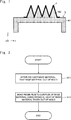
- Fig. 1 is a cross-sectional view of one example of the heat sink manufactured by the method of manufacturing the heat sink according to the first embodiment.
- the heat sink manufactured by the method of manufacturing the heat sink according to this embodiment includes a base material B and a resin film F, and is suitably used, for example, as a heat-radiation member used for a semiconductor device etc.
- the right-handed xyz rectangular coordinates shown in Fig. 1 and the other drawings are merely examples for explaining the positional relation of the components.
- the z-axis positive direction is a vertical upward direction and the xy plane is a horizontal plane throughout the drawings.
- the shape of the heat sink shown in Fig. 1 is merely an example, and may be changed in various ways.
- the base material B is a casting made of metal such as aluminum alloy having a high heat conductivity and is formed by die casting. As shown in Fig. 1 , the base material B includes a body part B1 and a radiator fin B2. The alternate long and short dash line shown in Fig. 1 is an exemplary border between the body part B1 and the radiator fin B2. Fig. 1 shows a state in which the heat sink is placed on a horizontal plane (xy plane) in such a way that the radiator fin B2 faces upward (z-axis positive side). However, the heat sink may be placed in a flexible manner so that the radiator fin B2 can be oriented to any direction when the heat sink is used.
- the body part B1 includes a flat plate part having a rectangular shape in a plane view and a pair of side walls that are protruded in a z-axis negative direction from the respective ends of the flat plate part in the x-axis direction and extended in the y-axis direction.
- the radiator fin B2 is extended in the y-axis direction on the upper surface of the flat plate part (principal surface on the z-axis positive side) in Fig. 1 .
- the radiator fin B2 is provided on a principal surface opposite to the principal surface of the flat plate part in which the side walls are provided.
- radiator fin B2 is a triangular shape in the example shown in Fig. 1 , this is merely an example and may instead be a rectangular shape or the like. Further, while four radiator fins B2 are formed in the example shown in Fig. 1 , the number of radiator fins B2 is not particularly limited.
- the resin film F is composed of, for example, heat-radiation resin such as polyamide imide or polyimide and constitutes a heat-radiation resin-coated film provided on the radiator fin B2. As shown in Fig. 1 , the resin film F is attached onto the radiator fin B2.
- the resin film F may be directly bonded to the radiator fin B2 or may be bonded thereto using adhesive.
- the resin film F has preferably a thickness between 10 and 100 ⁇ m.
- a sufficiently high heat radiation performance cannot be obtained.
- the thickness of the resin film F exceeds 100 ⁇ m, the heat radiation performance is hardly improved, which causes the cost performance to be reduced.
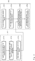
- FIG. 2 is a flowchart showing the method of manufacturing the heat sink according to the first embodiment.
- Fig. 1 as well as Fig. 2
- the method of manufacturing the heat sink according to the first embodiment will be explained.
- Step ST2 the resin film F is bonded to the surface of the base material B (Step ST2). That is, the heat-radiation resin-coated film is formed on the surface of the base material B by bonding the resin film F to the radiator fin B2 of the base material B.
- the resin film F which is the heat-radiation resin-coated film
- the resin film F is bonded to the surface of the base material B using the residual heat of the base material B taken out of the mold. Accordingly, there is no need to separately heat the base material B to form the heat-radiation resin-coated film, and thus productivity can be made high.
- the heat-radiation resin-coated film is formed on the surface of the base material B. It is therefore possible to make the thickness of the heat-radiation resin-coated film formed on the surface of the base material B uniform.
- the method of manufacturing the heat sink according to the first embodiment it is possible to eliminate the need for separately heating the base material in order to form the heat-radiation resin-coated film, thereby making productivity high, and make the thickness of the heat-radiation resin-coated film formed on the surface of the base material uniform.
- FIG. 3 is a flowchart showing the details of the method of manufacturing the heat sink according to the first embodiment.
- Steps ST11-ST13 in Fig. 3 correspond to Step ST1 shown in Fig. 2 , and correspond to the die-casting process of the base material B.
- Steps ST21-ST24 shown in Fig. 3 correspond to Step ST2 shown in Fig. 2 , and correspond to the bonding process of the resin film F.
- Step ST11-ST13 which constitute the die-casting process (Step ST1) of the base material B, will be explained.
- molten metal is supplied to a plunger sleeve (Step ST11).
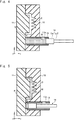
- Fig. 4 is a schematic cross-sectional view showing a state in which molten metal M is supplied to a plunger sleeve 13 in the die-casting process.
- a movable mold 11 is made to come into contact with a fixed mold 12 to form a cavity C. Then the molten metal M is supplied to the plunger sleeve 13 from a supply port 13a formed on the upper surface of the back side (x-axis negative direction) of the plunger sleeve 13 using, for example, a ladle (not shown).
- the plunger sleeve 13 is a cylindrical member having a central axis parallel to the x axis and is fitted into a through-hole of the fixed mold 12.
- the plunger tip 141 slides in the plunger sleeve 13 in the x-axis direction.
- the plunger tip 141 is coupled to a driving source for sliding (not shown) such as a cylinder via a plunger rod 142.
- the plunger tip 141 and the plunger rod 142 form a plunger 14.
- Fig. 5 is a schematic cross-sectional view showing a state in which the injection of the molten metal M into the cavity C is completed in the die-casting process.
- the plunger 14 is made to move forward in the plunger sleeve 13, and the molten metal M is injected into the cavity C via a runner R.
- the plunger 14 By making the plunger 14 move at a high speed, the cavity C can be filled with the molten metal M while pressure is being applied to the molten metal M.
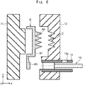
- Fig. 6 is a schematic cross-sectional view showing a state in which the base material B is taken out of the mold (the movable mold 11 and the fixed mold 12) in the die-casting process.
- the base material B that has been molded includes, besides the body part B1 and the radiator fin B2 shown in Fig. 1 , a biscuit/runner part B3.
- the alternate long and short dash line shown in the base material B in Fig. 6 is an exemplary border among the body part B1, the radiator fin B2, and the biscuit/runner part B3.
- the biscuit/runner part B3 includes a thick biscuit part surrounded by the end surface of the plunger tip 141 and the mold (the movable mold 11 and the fixed mold 12) and the like in which the molten metal M is solidified and a thin runner part in which the molten metal M is solidified in the runner R. Since the biscuit/runner part B3 is finally removed, it is not shown in Fig. 1 .
- Step ST21-ST24 which constitute the bonding process (Step ST2) of the resin film F, will be explained.
- Fig. 3 in the bonding process of the resin film F (Step ST2), first, the resin film is placed on a lower mold (Step ST21).
- Fig. 7 is a schematic side view showing a state in which the resin film F is placed on a lower mold 22 in the bonding process.
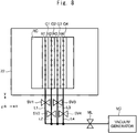
- Fig. 8 is a schematic plane view of the lower mold 22.
- the resin film F is placed on the lower mold (die for bonding) 22 in a state in which an upper mold 21 is elevated in the z-axis positive direction.
- the resin film F is preferably preheated.
- the resin film F may be preheated, for example, by placing it on a die-casting mold which is conducting the casting process.
- the die-casting mold includes the movable mold 11 and the fixed mold 12.
- the resin film F may be preheated by a heater.
- the upper mold 21 slides in the z-axis direction along a pair of columns 23 extended in the z-axis direction. Further, as shown in Figs. 7 and 8 , a recess RC that accommodates the body part B1 of the base material B is provided at the central part of the upper surface of the lower mold 22. As shown in Fig. 7 , the resin film F is placed on the bottom surface of the recess RC.
- grooves G having a shape that corresponds to the shape of the radiator fin B2 of the base material B are extended in the y-axis direction on the bottom surface of the recess RC.
- vacuum holes H that vacuum-adsorb the resin film F are formed.
- the vacuum holes H are connected to a vacuum generator VG via a pipe L provided inside and outside of the lower mold 22.
- a main valve MV is provided on the pipe L outside the lower mold 22. As shown in Fig. 7 , when the resin film F is placed on the lower mold 22, the main valve MV is closed.
- the diameter of each of the vacuum holes H is, for example, about 1 mm.
- a large number of vacuum holes H1 are formed to align along the longitudinal direction of the groove G1.
- the vacuum holes H1 are connected to the vacuum generator VG by a pipe L1.
- a sub valve SV1 is provided on the pipe L1.
- a large number of vacuum holes H2 are formed to align along the longitudinal direction of the groove G2.
- the vacuum holes H2 are connected to the vacuum generator VG by a pipe L2.
- a sub valve SV2 is provided on the pipe L2.
- a large number of vacuum holes H3 are formed to align along the longitudinal direction of the groove G3.
- the vacuum holes H3 are connected to the vacuum generator VG by a pipe L3.
- a sub valve SV3 is provided on the pipe L3.
- a large number of vacuum holes H4 are formed to align along the longitudinal direction of the groove G4.
- the vacuum holes H4 are connected to the vacuum generator VG by a pipe L4.
- a sub valve SV4 is provided on the pipe L4.
- the four sub valves SV1-SV4 are provided in parallel with respect to the vacuum generator VG.
- the grooves G1-G4 are able to adsorb the resin film F independently from one another.
- Fig. 9 is a schematic side view showing a state in which the resin film F is vacuum adsorbed to the lower mold 22 in the bonding process.
- the four sub valves SV1-SV4 shown in Fig. 8 are opened.
- the suction force via the vacuum holes H1-H4 as shown in Fig. 9 , the resin film F is vacuum adsorbed to the lower mold 22.
- the resin film F may be pulled between the grooves G adjacent to each other and the resin film F may be broken. Accordingly, by sequentially opening the sub valves SV1-SV4 in this order, the resin film F can be sequentially adsorbed from the groove G1 positioned at the end of the x-axis negative direction toward the groove G4 positioned at the end of the x-axis positive direction. It is therefore possible to suppress a situation in which the resin film F is pulled between the grooves G that are adjacent to each other and it is broken.
- the effects similar to those stated above can be obtained even when the sub valves SV1-SV4 are sequentially opened in such a way that the resin film F is sequentially adsorbed from the groove G4 positioned at the end of the x-axis positive direction toward the groove G1 positioned at the end of the x-axis negative direction.
- the effects similar to those stated above can be obtained even when the sub valves SV1-SV4 are sequentially opened in such a way the resin film F is sequentially adsorbed toward the grooves G1 and G4 positioned at the above respective ends after it is first adsorbed by the groove G2 or G3 positioned at the center.
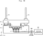
- Fig. 10 is a schematic side view showing a state in which the base material B is placed on the lower mold 22 and the base material B is pressed by the upper mold 21 in the bonding process.
- the base material B is placed on the lower mold 22 in such a way as to fit the radiator fin B2 of the base material B into the grooves G of the lower mold 22 that adsorbs the resin film F.
- the upper mold 21 is lowered to press the upper side (z-axis direction positive side) of the body part B1 of the base material B by the upper mold 21.
- the main valve MV and the four sub valves SV1-SV4 shown in Fig. 8 are closed to cancel the vacuum adsorption of the resin film F to the lower mold 22.
- the resin film F that has been vacuum adsorbed to the lower mold 22 is bonded to the surface of the radiator fin B2 of the base material B.
- the resin film F is bonded to the surface of the base material B. It is therefore possible to efficiently bond the resin film F to the surface of the base material B. Further, in this case, in a state in which the base material B is vacuum adsorbed to the lower mold 22, the resin film F is interposed between the lower mold 22 and the base material B. It is therefore possible to suppress wrinkles of the resin film F that may be generated at the bonding process.
- the temperature when the base material B is taken out of the die-casting mold (hereinafter this temperature will be referred to as a demolding temperature) is preferably 180-250 °C.
- the demolding temperature is lower than 180 °C, the resin film F is not firmly bonded to the base material B.
- the demolding temperature exceeds 250 °C, the molten metal M may remain inside the thick biscuit part in the biscuit/runner part B3, which may cause the thick biscuit part to burst.
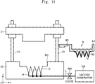
- Fig. 11 is a schematic side view showing a state in which the base material B to which the resin film F is bonded is taken out of the lower mold 22 in the bonding process. As shown in Fig. 11 , the upper mold 21 is elevated and the base material B to which the resin film F is bonded is taken out of the lower mold 22.
- the resin film F which is the heat-radiation resin-coated film
- the resin film F is bonded to the surface of the base material B using the residual heat of the base material B taken out of the die-casting mold (the movable mold 11 and the fixed mold 12). Accordingly, there is no need to separately heat the base material B in order to form the heat-radiation resin-coated film and thus productivity can be made high.
- the heat-radiation resin-coated film is formed on the surface of the base material B. Accordingly, it is possible to make the thickness of the heat-radiation resin-coated film formed on the surface of the base material B uniform.
- the method of manufacturing the heat sink according to the first embodiment it is possible to eliminate the need for separately heating the base material in order to form the heat-radiation resin-coated film, thereby making productivity high, and make the thickness of the heat-radiation resin-coated film formed on the surface of the base material uniform.
- the heat-radiation resin-coated film is formed on the surface of the base material B. Accordingly, it is possible to reduce the surface roughness of the heat-radiation resin-coated film compared to a case in which the heat-radiation resin-coated film is formed on the surface of the base material B by spraying the heat-radiation resin.
- the method of manufacturing the heat sink according to the first embodiment it is possible to form the heat-radiation resin-coated film only in an area in which the heat-radiation resin-coated film is necessary on the surface of the base material B.
- FIG. 12 is a flowchart showing details of the method of manufacturing the heat sink according to the second embodiment.
- Step ST31 in the method of manufacturing the heat sink according to the second embodiment, compared to the method of manufacturing the heat sink according to the first embodiment shown in Fig. 3 , after Step ST22 in which the resin film is vacuum adsorbed to the lower mold but before Step ST23 in which the base material is placed on the lower mold and the base material is pressed by the upper mold, adhesive is sprayed onto the resin film (Step ST31). That is, in the method of manufacturing the heat sink according to the second embodiment, the resin film F is bonded to the surface of the base material B using adhesive.
- Fig. 13 is a schematic side view showing a state in which adhesive is sprayed onto the resin film F in the bonding process. As shown in Fig. 13 , the adhesive is sprayed onto the resin film F that has been vacuum adsorbed to the lower mold 22 from above (z-axis positive direction) using a spraying device 30.
- the adhesive is preferably epoxy-based resin, and more preferably, epoxy-based resin having heat radiation.
- the demolding temperature of the base material B is preferably 120-200 °C. When the demolding temperature is lower than 120 °C, the adhesive is not sufficiently cured. When the demolding temperature exceeds 200 °C, the adhesive may be deteriorated.
- the resin film F is bonded to the surface of the base material B using adhesive. Accordingly, it is possible to improve the bonding force between the resin film F and the base material B compared to the method of manufacturing the heat sink according to the first embodiment in which the resin film F is directly bonded to the surface of the base material B.
- the resin film F may be bonded to the surface of the base material B manually, for example, without using a mold.
- the resin film F may be bonded to the surface of the base material B by pressing the resin film F onto the surface of the base material B using air.
- a method of manufacturing a heat sink is a method of manufacturing a heat sink including a base material having a surface on which a heat-radiation resin-coated film is formed, the method comprising: taking the base material out of a die-casting mold after the base material is die-cast; and forming the heat-radiation resin-coated film on the surface of the base material using residual heat of the base material taken out of the die-casting mold.
- the heat-radiation resin-coated film is formed on the surface of the base material by bonding a heat-radiation resin film to the surface of the base material.
Landscapes
- Engineering & Computer Science (AREA)
- Mechanical Engineering (AREA)
- Physics & Mathematics (AREA)
- Thermal Sciences (AREA)
- General Engineering & Computer Science (AREA)
- Fluid Mechanics (AREA)
- Manufacturing & Machinery (AREA)
- Cooling Or The Like Of Semiconductors Or Solid State Devices (AREA)
- Cooling Or The Like Of Electrical Apparatus (AREA)
Abstract
Description
- The present disclosure relates to a method of manufacturing a heat sink.
- Japanese Unexamined Patent Application Publication No.
57-202683 - The present inventors have found the following problems in the method of manufacturing the heat sink including the base material having the surface on which the heat-radiation resin-coated film is formed.
- In the method disclosed in Japanese Unexamined Patent Application Publication No.
57-202683 - On the other hand, it may be possible to apply the heat-radiation resin onto the surface of the base material as a method of forming the heat-radiation resin-coated film on the surface of the base material without using a mold. Specifically, the heat-radiation resin is applied to the base material having a high temperature since it has just been die-cast by spraying the heat-radiation resin onto the base material or dropping the heat-radiation resin onto the base material. However, even in the method of applying the heat-radiation resin to the surface of the base material without using a mold, since the thickness of the heat-radiation resin-coated film tends to vary depending on the place on this film, it is difficult to make the thickness of the heat-radiation resin-coated film uniform.
- The present disclosure has been made in view of the aforementioned circumstances and provides a method of manufacturing a heat sink in which there is no need to separately heat the base material in order to form the heat-radiation resin-coated film and thus productivity can be made high, and the thickness of the heat-radiation resin-coated film formed on the surface of the base material can be made uniform.
- A method of manufacturing a heat sink according to one aspect of the present disclosure is a method of manufacturing a heat sink including a base material having a surface on which a heat-radiation resin-coated film is formed, the method including: taking the base material out of a die-casting mold after the base material is die-cast; and forming the heat-radiation resin-coated film on the surface of the base material using residual heat of the base material taken out of the die-casting mold, in forming the heat-radiation resin-coated film, the heat-radiation resin-coated film is formed on the surface of the base material by bonding a heat-radiation resin film to the surface of the base material.
- In the method of manufacturing the heat sink according to one aspect of the present disclosure, in forming the heat-radiation resin-coated film on the surface of the base material using residual heat of the base material taken out of the die-casting mold, the heat-radiation resin film is bonded to the surface of the base material, to thereby form the heat-radiation resin-coated film on the surface of the base material. Accordingly, it is possible to eliminate the need for separately heating the base material in order to form the heat-radiation resin-coated film, thereby making productivity high, and make the thickness of the heat-radiation resin-coated film formed on the surface of the base material uniform.
- By interposing the heat-radiation resin film between a die for bonding having a surface shape that corresponds to the surface shape of the base material and the base material, the heat-radiation resin film may be bonded to the surface of the base material. According to this structure, the heat-radiation resin film can be efficiently bonded to the surface of the base material.
- A vacuum hole for vacuum adsorption may be provided in the die for bonding, and the heat-radiation resin film may be interposed between the die for bonding and the base material in a state in which the base material is vacuum adsorbed to the die for bonding. According to this structure, it is possible to suppress wrinkles of the resin film F that may occur at the bonding process.
- Adhesive may be applied to a surface of the heat-radiation resin film, and the heat-radiation resin film may be bonded to the surface of the base material using the adhesive. According to this structure, it is possible to improve the bonding force between the heat-radiation resin film and the base material.
- The adhesive may be made of heat-radiation resin.
- According to the present disclosure, it is possible to provide a method of manufacturing a heat sink in which there is no need to separately heat the base material in order to form the heat-radiation resin-coated film and thus productivity can be made high, and the thickness of the heat-radiation resin-coated film formed on the surface of the base material can be made uniform.
- The above and other objects, features and advantages of the present invention will become more fully understood from the detailed description given hereinbelow and the accompanying drawings which are given by way of illustration only, and thus are not to be considered as limiting the present invention.
-
-
Fig. 1 is a cross-sectional view of one example of a heat sink manufactured by a method of manufacturing a heat sink according to a first embodiment; -
Fig. 2 is a flowchart showing the method of manufacturing the heat sink according to the first embodiment; -
Fig. 3 is a flowchart showing details of the method of manufacturing the heat sink according to the first embodiment; -
Fig. 4 is a schematic cross-sectional view showing a state in which molten metal M is supplied to aplunger sleeve 13 in a die-casting process; -
Fig. 5 is a schematic cross-sectional view showing a state in which injection of the molten metal M into a cavity C is completed in the die-casting process; -
Fig. 6 is a schematic cross-sectional view showing a state in which a base material B is taken out of a mold (amovable mold 11 and a fixed mold 12) in the die-casting process; -
Fig. 7 is a schematic side view showing a state in which a resin film F is placed on alower mold 22 in a bonding process; -
Fig. 8 is a schematic plane view of thelower mold 22; -
Fig. 9 is a schematic side view showing a state in which the resin film F is vacuum adsorbed to thelower mold 22 in the bonding process; -
Fig. 10 is a schematic side view showing a state in which the base material B is placed on thelower mold 22 and the base material B is pressed by anupper mold 21 in the bonding process; -
Fig. 11 is a schematic side view showing a state in which the base material B to which the resin film F has been bonded is taken out of thelower mold 22 in the bonding process; -
Fig. 12 is a flowchart showing details of a method of manufacturing a heat sink according to a second embodiment; and -
Fig. 13 is a schematic side view showing a state in which adhesive is sprayed onto the resin film F in the bonding process. - Hereinafter, specific embodiments to which the present disclosure has been applied will be explained in detail with reference to the drawings. However, the present disclosure is not limited to the following embodiments. Further, in order to clarify the explanation, the following descriptions and the drawings are simplified as appropriate.
- With reference first to
Fig. 1 , a heat sink manufactured by a method of manufacturing a heat sink according to a first embodiment will be explained.Fig. 1 is a cross-sectional view of one example of the heat sink manufactured by the method of manufacturing the heat sink according to the first embodiment. As shown inFig. 1 , the heat sink manufactured by the method of manufacturing the heat sink according to this embodiment includes a base material B and a resin film F, and is suitably used, for example, as a heat-radiation member used for a semiconductor device etc. - As a matter of course, the right-handed xyz rectangular coordinates shown in
Fig. 1 and the other drawings are merely examples for explaining the positional relation of the components. Typically, the z-axis positive direction is a vertical upward direction and the xy plane is a horizontal plane throughout the drawings. Further, the shape of the heat sink shown inFig. 1 is merely an example, and may be changed in various ways. - The base material B is a casting made of metal such as aluminum alloy having a high heat conductivity and is formed by die casting. As shown in
Fig. 1 , the base material B includes a body part B1 and a radiator fin B2. The alternate long and short dash line shown inFig. 1 is an exemplary border between the body part B1 and the radiator fin B2.Fig. 1 shows a state in which the heat sink is placed on a horizontal plane (xy plane) in such a way that the radiator fin B2 faces upward (z-axis positive side). However, the heat sink may be placed in a flexible manner so that the radiator fin B2 can be oriented to any direction when the heat sink is used. - In the example shown in
Fig. 1 , the body part B1 includes a flat plate part having a rectangular shape in a plane view and a pair of side walls that are protruded in a z-axis negative direction from the respective ends of the flat plate part in the x-axis direction and extended in the y-axis direction. - The radiator fin B2 is extended in the y-axis direction on the upper surface of the flat plate part (principal surface on the z-axis positive side) in
Fig. 1 . In other words, the radiator fin B2 is provided on a principal surface opposite to the principal surface of the flat plate part in which the side walls are provided. - While the cross-sectional shape of the radiator fin B2 is a triangular shape in the example shown in
Fig. 1 , this is merely an example and may instead be a rectangular shape or the like. Further, while four radiator fins B2 are formed in the example shown inFig. 1 , the number of radiator fins B2 is not particularly limited. - The resin film F is composed of, for example, heat-radiation resin such as polyamide imide or polyimide and constitutes a heat-radiation resin-coated film provided on the radiator fin B2. As shown in
Fig. 1 , the resin film F is attached onto the radiator fin B2. - The resin film F may be directly bonded to the radiator fin B2 or may be bonded thereto using adhesive.
- The resin film F has preferably a thickness between 10 and 100 µm. When the thickness of the resin film F is smaller than 10 µm, a sufficiently high heat radiation performance cannot be obtained. On the other hand, when the thickness of the resin film F exceeds 100 µm, the heat radiation performance is hardly improved, which causes the cost performance to be reduced.
- With reference next to
Fig. 2 , a method of manufacturing the heat sink according to the first embodiment will be explained.Fig. 2 is a flowchart showing the method of manufacturing the heat sink according to the first embodiment. With reference toFig. 1 as well asFig. 2 , the method of manufacturing the heat sink according to the first embodiment will be explained. - First, as shown in
Fig. 2 , after the base material B shown inFig. 1 is die-cast, the base material B is taken out of the mold (Step ST1). - Next, as shown in
Fig. 2 , using residual heat of the base material B taken out of the mold, as shown inFig. 1 , the resin film F is bonded to the surface of the base material B (Step ST2). That is, the heat-radiation resin-coated film is formed on the surface of the base material B by bonding the resin film F to the radiator fin B2 of the base material B. - As described above, in the method of manufacturing the heat sink according to the first embodiment, the resin film F, which is the heat-radiation resin-coated film, is bonded to the surface of the base material B using the residual heat of the base material B taken out of the mold. Accordingly, there is no need to separately heat the base material B to form the heat-radiation resin-coated film, and thus productivity can be made high.
- Further, by bonding the resin film F having a uniform thickness to the surface of the base material B, the heat-radiation resin-coated film is formed on the surface of the base material B. It is therefore possible to make the thickness of the heat-radiation resin-coated film formed on the surface of the base material B uniform.
- That is, in the method of manufacturing the heat sink according to the first embodiment, it is possible to eliminate the need for separately heating the base material in order to form the heat-radiation resin-coated film, thereby making productivity high, and make the thickness of the heat-radiation resin-coated film formed on the surface of the base material uniform.
- With reference next to
Fig. 3 , details of the method of manufacturing the heat sink according to the first embodiment will be explained.Fig. 3 is a flowchart showing the details of the method of manufacturing the heat sink according to the first embodiment. - Steps ST11-ST13 in
Fig. 3 correspond to Step ST1 shown inFig. 2 , and correspond to the die-casting process of the base material B. Steps ST21-ST24 shown inFig. 3 correspond to Step ST2 shown inFig. 2 , and correspond to the bonding process of the resin film F. - First, Steps ST11-ST13, which constitute the die-casting process (Step ST1) of the base material B, will be explained.
- As shown in
Fig. 3 , in the die-casting process (Step ST1) of the base material B, molten metal is supplied to a plunger sleeve (Step ST11).Fig. 4 is a schematic cross-sectional view showing a state in which molten metal M is supplied to aplunger sleeve 13 in the die-casting process. - Specifically, as shown in
Fig. 4 , in a state in which aplunger tip 141 is retracted in the x-axis positive direction in theplunger sleeve 13, amovable mold 11 is made to come into contact with a fixedmold 12 to form a cavity C. Then the molten metal M is supplied to theplunger sleeve 13 from asupply port 13a formed on the upper surface of the back side (x-axis negative direction) of theplunger sleeve 13 using, for example, a ladle (not shown). - As shown in
Fig. 4 , theplunger sleeve 13 is a cylindrical member having a central axis parallel to the x axis and is fitted into a through-hole of the fixedmold 12. Theplunger tip 141 slides in theplunger sleeve 13 in the x-axis direction. Theplunger tip 141 is coupled to a driving source for sliding (not shown) such as a cylinder via aplunger rod 142. Theplunger tip 141 and theplunger rod 142 form aplunger 14. - Next, as shown in
Fig. 3 , the molten metal is injected into the cavity and the base material is molded (Step ST12).Fig. 5 is a schematic cross-sectional view showing a state in which the injection of the molten metal M into the cavity C is completed in the die-casting process. - Specifically, as shown in
Fig. 5 , theplunger 14 is made to move forward in theplunger sleeve 13, and the molten metal M is injected into the cavity C via a runner R. By making theplunger 14 move at a high speed, the cavity C can be filled with the molten metal M while pressure is being applied to the molten metal M. - Next, as shown in
Fig. 3 , the molten metal is injected into the cavity and the base material is taken out of the mold (Step ST13).Fig. 6 is a schematic cross-sectional view showing a state in which the base material B is taken out of the mold (themovable mold 11 and the fixed mold 12) in the die-casting process. - Specifically, as shown in
Fig. 6 , after the molten metal M is solidified in the cavity C, themovable mold 11 is separated from the fixedmold 12 and the base material B that has been molded is obtained. As shown inFig. 6 , the base material B that has been molded includes, besides the body part B1 and the radiator fin B2 shown inFig. 1 , a biscuit/runner part B3. The alternate long and short dash line shown in the base material B inFig. 6 is an exemplary border among the body part B1, the radiator fin B2, and the biscuit/runner part B3. - The biscuit/runner part B3 includes a thick biscuit part surrounded by the end surface of the
plunger tip 141 and the mold (themovable mold 11 and the fixed mold 12) and the like in which the molten metal M is solidified and a thin runner part in which the molten metal M is solidified in the runner R. Since the biscuit/runner part B3 is finally removed, it is not shown inFig. 1 . - Next, Steps ST21-ST24, which constitute the bonding process (Step ST2) of the resin film F, will be explained.
- As shown in
Fig. 3 , in the bonding process of the resin film F (Step ST2), first, the resin film is placed on a lower mold (Step ST21).Fig. 7 is a schematic side view showing a state in which the resin film F is placed on alower mold 22 in the bonding process. Further,Fig. 8 is a schematic plane view of thelower mold 22. - Specifically, as shown in
Fig. 7 , the resin film F is placed on the lower mold (die for bonding) 22 in a state in which anupper mold 21 is elevated in the z-axis positive direction. The resin film F is preferably preheated. The resin film F may be preheated, for example, by placing it on a die-casting mold which is conducting the casting process. The die-casting mold includes themovable mold 11 and the fixedmold 12. As a matter of course, the resin film F may be preheated by a heater. - The
upper mold 21 slides in the z-axis direction along a pair ofcolumns 23 extended in the z-axis direction. Further, as shown inFigs. 7 and8 , a recess RC that accommodates the body part B1 of the base material B is provided at the central part of the upper surface of thelower mold 22. As shown inFig. 7 , the resin film F is placed on the bottom surface of the recess RC. - Further, as shown in
Fig. 7 , grooves G having a shape that corresponds to the shape of the radiator fin B2 of the base material B are extended in the y-axis direction on the bottom surface of the recess RC. In the bottom part of the grooves G, vacuum holes H that vacuum-adsorb the resin film F are formed. The vacuum holes H are connected to a vacuum generator VG via a pipe L provided inside and outside of thelower mold 22. A main valve MV is provided on the pipe L outside thelower mold 22. As shown inFig. 7 , when the resin film F is placed on thelower mold 22, the main valve MV is closed. The diameter of each of the vacuum holes H is, for example, about 1 mm. - As shown in
Fig. 8 as an example, four grooves G1-G4 are formed. In the groove G1, a large number of vacuum holes H1 are formed to align along the longitudinal direction of the groove G1. The vacuum holes H1 are connected to the vacuum generator VG by a pipe L1. A sub valve SV1 is provided on the pipe L1. - In a similar way, in the groove G2, a large number of vacuum holes H2 are formed to align along the longitudinal direction of the groove G2. The vacuum holes H2 are connected to the vacuum generator VG by a pipe L2. A sub valve SV2 is provided on the pipe L2.
- In a similar way, in the groove G3, a large number of vacuum holes H3 are formed to align along the longitudinal direction of the groove G3. The vacuum holes H3 are connected to the vacuum generator VG by a pipe L3. A sub valve SV3 is provided on the pipe L3.
- In a groove G4, a large number of vacuum holes H4 are formed to align along the longitudinal direction of the groove G4. The vacuum holes H4 are connected to the vacuum generator VG by a pipe L4. A sub valve SV4 is provided on the pipe L4.
- The four sub valves SV1-SV4 are provided in parallel with respect to the vacuum generator VG.
- According to the aforementioned structure, the grooves G1-G4 are able to adsorb the resin film F independently from one another.
- Next, as shown in
Fig. 3 , the resin film is vacuum adsorbed to the lower mold (Step ST22).Fig. 9 is a schematic side view showing a state in which the resin film F is vacuum adsorbed to thelower mold 22 in the bonding process. - Specifically, after the vacuum generator VG is driven and the main valve MV is opened, the four sub valves SV1-SV4 shown in
Fig. 8 are opened. By the suction force via the vacuum holes H1-H4, as shown inFig. 9 , the resin film F is vacuum adsorbed to thelower mold 22. - When, for example, the four sub valves SV1-SV4 are opened at the same time, the resin film F may be pulled between the grooves G adjacent to each other and the resin film F may be broken. Accordingly, by sequentially opening the sub valves SV1-SV4 in this order, the resin film F can be sequentially adsorbed from the groove G1 positioned at the end of the x-axis negative direction toward the groove G4 positioned at the end of the x-axis positive direction. It is therefore possible to suppress a situation in which the resin film F is pulled between the grooves G that are adjacent to each other and it is broken.
- As a matter of course, the effects similar to those stated above can be obtained even when the sub valves SV1-SV4 are sequentially opened in such a way that the resin film F is sequentially adsorbed from the groove G4 positioned at the end of the x-axis positive direction toward the groove G1 positioned at the end of the x-axis negative direction. Alternatively, the effects similar to those stated above can be obtained even when the sub valves SV1-SV4 are sequentially opened in such a way the resin film F is sequentially adsorbed toward the grooves G1 and G4 positioned at the above respective ends after it is first adsorbed by the groove G2 or G3 positioned at the center.
- Next, as shown in
Fig. 3 , the base material having a high temperature taken out of the die-casting mold is placed on the lower mold and the base material is pressed by the upper mold (Step ST23).Fig. 10 is a schematic side view showing a state in which the base material B is placed on thelower mold 22 and the base material B is pressed by theupper mold 21 in the bonding process. - Specifically, as shown in
Fig. 10 , the base material B is placed on thelower mold 22 in such a way as to fit the radiator fin B2 of the base material B into the grooves G of thelower mold 22 that adsorbs the resin film F. Then theupper mold 21 is lowered to press the upper side (z-axis direction positive side) of the body part B1 of the base material B by theupper mold 21. After that, the main valve MV and the four sub valves SV1-SV4 shown inFig. 8 are closed to cancel the vacuum adsorption of the resin film F to thelower mold 22. By the residual heat of the base material B which has just been die-cast and hence has a high temperature, the resin film F that has been vacuum adsorbed to thelower mold 22 is bonded to the surface of the radiator fin B2 of the base material B. - As described above, by interposing the resin film F between the
lower mold 22 having a surface shape that corresponds to the shape of the surface of the base material B and the base material B, the resin film F is bonded to the surface of the base material B. It is therefore possible to efficiently bond the resin film F to the surface of the base material B. Further, in this case, in a state in which the base material B is vacuum adsorbed to thelower mold 22, the resin film F is interposed between thelower mold 22 and the base material B. It is therefore possible to suppress wrinkles of the resin film F that may be generated at the bonding process. - When the resin film F is made of thermoplastic polyamide imide or polyimide, the temperature when the base material B is taken out of the die-casting mold (hereinafter this temperature will be referred to as a demolding temperature) is preferably 180-250 °C. When the demolding temperature is lower than 180 °C, the resin film F is not firmly bonded to the base material B. When the demolding temperature exceeds 250 °C, the molten metal M may remain inside the thick biscuit part in the biscuit/runner part B3, which may cause the thick biscuit part to burst.
- Lastly, as shown in
Fig. 3 , the base material to which the resin film is bonded is taken out of the lower mold (Step ST24).Fig. 11 is a schematic side view showing a state in which the base material B to which the resin film F is bonded is taken out of thelower mold 22 in the bonding process. As shown inFig. 11 , theupper mold 21 is elevated and the base material B to which the resin film F is bonded is taken out of thelower mold 22. - As described above, in the method of manufacturing the heat sink according to the first embodiment, the resin film F, which is the heat-radiation resin-coated film, is bonded to the surface of the base material B using the residual heat of the base material B taken out of the die-casting mold (the
movable mold 11 and the fixed mold 12). Accordingly, there is no need to separately heat the base material B in order to form the heat-radiation resin-coated film and thus productivity can be made high. - Further, by bonding the resin film F having a uniform thickness to the surface of the base material B, the heat-radiation resin-coated film is formed on the surface of the base material B. Accordingly, it is possible to make the thickness of the heat-radiation resin-coated film formed on the surface of the base material B uniform.
- That is, in the method of manufacturing the heat sink according to the first embodiment, it is possible to eliminate the need for separately heating the base material in order to form the heat-radiation resin-coated film, thereby making productivity high, and make the thickness of the heat-radiation resin-coated film formed on the surface of the base material uniform.
- Further, in the method of manufacturing the heat sink according to the first embodiment, by bonding the resin film F having heat radiation to the surface of the base material B, the heat-radiation resin-coated film is formed on the surface of the base material B. Accordingly, it is possible to reduce the surface roughness of the heat-radiation resin-coated film compared to a case in which the heat-radiation resin-coated film is formed on the surface of the base material B by spraying the heat-radiation resin.
- Further, in the method of manufacturing the heat sink according to the first embodiment, it is possible to form the heat-radiation resin-coated film only in an area in which the heat-radiation resin-coated film is necessary on the surface of the base material B.
- Further, when spray coating is carried out, there may be an area in which the heat-radiation resin-coated film cannot be formed on the surface of the base material B due to a reason that the radiator fin B2 interrupts spray coating or the like. On the other hand, in the method of manufacturing the heat sink according to the first embodiment, it is possible to suppress the occurrence of the area in which the heat-radiation resin-coated film cannot be formed compared to the case in which spray coating is carried out.
- With reference next to
Fig. 12 , a method of manufacturing a heat sink according to a second embodiment will be explained.Fig. 12 is a flowchart showing details of the method of manufacturing the heat sink according to the second embodiment. - As shown in
Fig. 12 , in the method of manufacturing the heat sink according to the second embodiment, compared to the method of manufacturing the heat sink according to the first embodiment shown inFig. 3 , after Step ST22 in which the resin film is vacuum adsorbed to the lower mold but before Step ST23 in which the base material is placed on the lower mold and the base material is pressed by the upper mold, adhesive is sprayed onto the resin film (Step ST31). That is, in the method of manufacturing the heat sink according to the second embodiment, the resin film F is bonded to the surface of the base material B using adhesive. -
Fig. 13 is a schematic side view showing a state in which adhesive is sprayed onto the resin film F in the bonding process. As shown inFig. 13 , the adhesive is sprayed onto the resin film F that has been vacuum adsorbed to thelower mold 22 from above (z-axis positive direction) using aspraying device 30. - The adhesive is preferably epoxy-based resin, and more preferably, epoxy-based resin having heat radiation. In this case, the demolding temperature of the base material B is preferably 120-200 °C. When the demolding temperature is lower than 120 °C, the adhesive is not sufficiently cured. When the demolding temperature exceeds 200 °C, the adhesive may be deteriorated.
- In the method of manufacturing the heat sink according to the second embodiment, the resin film F is bonded to the surface of the base material B using adhesive. Accordingly, it is possible to improve the bonding force between the resin film F and the base material B compared to the method of manufacturing the heat sink according to the first embodiment in which the resin film F is directly bonded to the surface of the base material B.
- Note that the present disclosure is not limited to the aforementioned embodiments and may be changed as appropriate without departing from the spirit of the present disclosure.
- The resin film F may be bonded to the surface of the base material B manually, for example, without using a mold. Alternatively, the resin film F may be bonded to the surface of the base material B by pressing the resin film F onto the surface of the base material B using air.
- From the invention thus described, it will be obvious that the embodiments of the invention may be varied in many ways. Such variations are not to be regarded as a departure from the spirit and scope of the invention, and all such modifications as would be obvious to one skilled in the art are intended for inclusion within the scope of the following claims.
- A method of manufacturing a heat sink according to one aspect of the present disclosure is a method of manufacturing a heat sink including a base material having a surface on which a heat-radiation resin-coated film is formed, the method comprising: taking the base material out of a die-casting mold after the base material is die-cast; and forming the heat-radiation resin-coated film on the surface of the base material using residual heat of the base material taken out of the die-casting mold. In forming the heat-radiation resin-coated film, the heat-radiation resin-coated film is formed on the surface of the base material by bonding a heat-radiation resin film to the surface of the base material.
Claims (5)
- A method of manufacturing a heat sink including a base material having a surface on which a heat-radiation resin-coated film is formed, the method comprising:taking the base material (B) out of a die-casting mold (11, 12) after the base material is die-cast; andforming the heat-radiation resin-coated film (F) on the surface of the base material using residual heat of the base material taken out of the die-casting mold, whereinin forming the heat-radiation resin-coated film, the heat-radiation resin-coated film is formed on the surface of the base material by bonding a heat-radiation resin film to the surface of the base material.
- The method of manufacturing the heat sink according to Claim 1, wherein the heat-radiation resin film is bonded to the surface of the base material by interposing the heat-radiation resin film between a die for bonding (22) having a surface shape that corresponds to the surface shape of the base material and the base material.
- The method of manufacturing the heat sink according to Claim 2, wherein
a vacuum hole for vacuum adsorption (H) is provided in the die for bonding, and
the heat-radiation resin film is interposed between the die for bonding and the base material in a state in which the base material is vacuum adsorbed to the die for bonding. - The method of manufacturing the heat sink according to any one of Claims 1 to 3, comprising:applying adhesive to a surface of the heat-radiation resin film; andbonding the heat-radiation resin film to the surface of the base material using the adhesive.
- The method of manufacturing the heat sink according to Claim 4, wherein the adhesive is made of heat-radiation resin.
Applications Claiming Priority (1)
| Application Number | Priority Date | Filing Date | Title |
|---|---|---|---|
| JP2017073806A JP6766734B2 (en) | 2017-04-03 | 2017-04-03 | How to make a heat sink |
Publications (2)
| Publication Number | Publication Date |
|---|---|
| EP3385050A1 true EP3385050A1 (en) | 2018-10-10 |
| EP3385050B1 EP3385050B1 (en) | 2019-08-21 |
Family
ID=61192765
Family Applications (1)
| Application Number | Title | Priority Date | Filing Date |
|---|---|---|---|
| EP18156243.0A Active EP3385050B1 (en) | 2017-04-03 | 2018-02-12 | Method of manufacturing heat sink |
Country Status (5)
| Country | Link |
|---|---|
| US (1) | US20180283808A1 (en) |
| EP (1) | EP3385050B1 (en) |
| JP (1) | JP6766734B2 (en) |
| CN (1) | CN108688135B (en) |
| TW (1) | TWI658882B (en) |
Families Citing this family (2)
| Publication number | Priority date | Publication date | Assignee | Title |
|---|---|---|---|---|
| US20210134510A1 (en) * | 2019-10-31 | 2021-05-06 | Analog Devices International Unlimited Company | Electronic device |
| US12315776B2 (en) | 2021-11-08 | 2025-05-27 | Analog Devices, Inc. | Integrated device package with an integrated heat sink |
Citations (2)
| Publication number | Priority date | Publication date | Assignee | Title |
|---|---|---|---|---|
| JPS57202683A (en) | 1981-06-08 | 1982-12-11 | Toshiba Denki Kigu Kk | Method of producing heat radiating base for electric heater |
| EP2656991A2 (en) * | 2012-04-26 | 2013-10-30 | Hedrich GmbH | Storage container for cast resin and a method and device for casting cast resin |
Family Cites Families (9)
| Publication number | Priority date | Publication date | Assignee | Title |
|---|---|---|---|---|
| ES2103265T3 (en) * | 1990-02-10 | 1997-09-16 | Bayer Ag | PROCEDURE FOR OBTAINING MULTILAYER MOLDING BODIES. |
| US6623677B1 (en) * | 2000-07-21 | 2003-09-23 | Bayer Corporation | Decorated article made by film insert molding |
| JP2009051121A (en) * | 2007-08-28 | 2009-03-12 | Suzuki Motor Corp | In-mold molding method |
| JP5086904B2 (en) * | 2008-06-10 | 2012-11-28 | キヤノン株式会社 | IMAGING DEVICE, IMAGING DEVICE CONTROL METHOD, PROGRAM, AND RECORDING MEDIUM |
| WO2015148945A1 (en) * | 2014-03-28 | 2015-10-01 | Micronics, Inc. | Methods and apparatus for lamination of rigid substrates by sequential application of vacuum and mechanical force |
| CN205793713U (en) * | 2016-05-26 | 2016-12-07 | 合肥鑫晟光电科技有限公司 | The attaching device of conducting resinl and rework system |
| JP2018043251A (en) * | 2016-09-12 | 2018-03-22 | トヨタ自動車株式会社 | Heat sink manufacturing method |
| US10730276B2 (en) * | 2017-01-17 | 2020-08-04 | Maven Optronics Co., Ltd. | System and method for vacuum film lamination |
| KR102395194B1 (en) * | 2017-06-21 | 2022-05-06 | 삼성전자주식회사 | Wafer bonding apparatus, and wafer bonding system comprising the same apparatus |
-
2017
- 2017-04-03 JP JP2017073806A patent/JP6766734B2/en not_active Expired - Fee Related
-
2018
- 2018-02-12 EP EP18156243.0A patent/EP3385050B1/en active Active
- 2018-02-14 US US15/896,215 patent/US20180283808A1/en not_active Abandoned
- 2018-03-01 TW TW107106714A patent/TWI658882B/en not_active IP Right Cessation
- 2018-03-30 CN CN201810287057.2A patent/CN108688135B/en not_active Expired - Fee Related
Patent Citations (2)
| Publication number | Priority date | Publication date | Assignee | Title |
|---|---|---|---|---|
| JPS57202683A (en) | 1981-06-08 | 1982-12-11 | Toshiba Denki Kigu Kk | Method of producing heat radiating base for electric heater |
| EP2656991A2 (en) * | 2012-04-26 | 2013-10-30 | Hedrich GmbH | Storage container for cast resin and a method and device for casting cast resin |
Also Published As
| Publication number | Publication date |
|---|---|
| TW201836734A (en) | 2018-10-16 |
| EP3385050B1 (en) | 2019-08-21 |
| CN108688135B (en) | 2021-05-07 |
| CN108688135A (en) | 2018-10-23 |
| US20180283808A1 (en) | 2018-10-04 |
| JP6766734B2 (en) | 2020-10-14 |
| JP2018176166A (en) | 2018-11-15 |
| TWI658882B (en) | 2019-05-11 |
Similar Documents
| Publication | Publication Date | Title |
|---|---|---|
| JP5906528B2 (en) | Mold and resin molding apparatus using the same | |
| JP2023027039A (en) | Cosmetic stick comprising two compositions with surface in relief, method for manufacturing such cosmetic stick, and device | |
| EP3385050B1 (en) | Method of manufacturing heat sink | |
| JP6175592B1 (en) | Resin sealing device and resin sealing method | |
| CN111216301B (en) | Molding die, resin molding device, and method for manufacturing resin molded article | |
| CN1154544C (en) | Method for applying paste | |
| JP2013123849A (en) | Resin sealing device and resin sealing method | |
| JP5892683B2 (en) | Resin sealing method | |
| CN113573867A (en) | Resin molding device and method for manufacturing resin molded product | |
| US6306331B1 (en) | Ultra mold for encapsulating very thin packages | |
| CN109382965A (en) | The manufacturing method of the carrying mechanism of synthetic resin, resin molding apparatus and synthetic resin | |
| TW201902650A (en) | Molding mold and resin molding method | |
| KR102393495B1 (en) | Resin molded product manufacturing method and resin molding apparatus | |
| WO2018146755A1 (en) | Resin sealing device and resin sealing method | |
| JP5771865B2 (en) | Mold | |
| JP5776093B2 (en) | Resin sealing device | |
| TWI290092B (en) | Resin casting mold and method of casting resin | |
| WO2018139631A1 (en) | Resin sealing device and resin sealing method | |
| US20240408802A1 (en) | Mold for resin molding, resin molding apparatus, and method for producing resin molded article | |
| TWI455252B (en) | A mold release mechanism for a light emitting diode package process | |
| JP2019111692A (en) | Resin molding apparatus and method of manufacturing resin molded article | |
| JP2009148934A (en) | Resin sealing mold and usage method of resin sealing mold | |
| JPS63107532A (en) | molding mold | |
| JP2009012253A (en) | Mold assembly for molding tabular molded article by injection compression molding, and its molding method | |
| JP6749279B2 (en) | Mold and resin molding equipment |
Legal Events
| Date | Code | Title | Description |
|---|---|---|---|
| PUAI | Public reference made under article 153(3) epc to a published international application that has entered the european phase |
Free format text: ORIGINAL CODE: 0009012 |
|
| STAA | Information on the status of an ep patent application or granted ep patent |
Free format text: STATUS: REQUEST FOR EXAMINATION WAS MADE |
|
| 17P | Request for examination filed |
Effective date: 20180212 |
|
| AK | Designated contracting states |
Kind code of ref document: A1 Designated state(s): AL AT BE BG CH CY CZ DE DK EE ES FI FR GB GR HR HU IE IS IT LI LT LU LV MC MK MT NL NO PL PT RO RS SE SI SK SM TR |
|
| AX | Request for extension of the european patent |
Extension state: BA ME |
|
| GRAP | Despatch of communication of intention to grant a patent |
Free format text: ORIGINAL CODE: EPIDOSNIGR1 |
|
| STAA | Information on the status of an ep patent application or granted ep patent |
Free format text: STATUS: GRANT OF PATENT IS INTENDED |
|
| INTG | Intention to grant announced |
Effective date: 20190327 |
|
| RIC1 | Information provided on ipc code assigned before grant |
Ipc: B22D 19/00 20060101ALI20190315BHEP Ipc: B29L 31/18 20060101ALN20190315BHEP Ipc: B29C 39/42 20060101AFI20190315BHEP Ipc: B29C 41/50 20060101ALI20190315BHEP |
|
| GRAS | Grant fee paid |
Free format text: ORIGINAL CODE: EPIDOSNIGR3 |
|
| GRAA | (expected) grant |
Free format text: ORIGINAL CODE: 0009210 |
|
| STAA | Information on the status of an ep patent application or granted ep patent |
Free format text: STATUS: THE PATENT HAS BEEN GRANTED |
|
| AK | Designated contracting states |
Kind code of ref document: B1 Designated state(s): AL AT BE BG CH CY CZ DE DK EE ES FI FR GB GR HR HU IE IS IT LI LT LU LV MC MK MT NL NO PL PT RO RS SE SI SK SM TR |
|
| REG | Reference to a national code |
Ref country code: GB Ref legal event code: FG4D |
|
| REG | Reference to a national code |
Ref country code: CH Ref legal event code: EP |
|
| REG | Reference to a national code |
Ref country code: DE Ref legal event code: R096 Ref document number: 602018000440 Country of ref document: DE |
|
| REG | Reference to a national code |
Ref country code: AT Ref legal event code: REF Ref document number: 1169204 Country of ref document: AT Kind code of ref document: T Effective date: 20190915 |
|
| REG | Reference to a national code |
Ref country code: IE Ref legal event code: FG4D |
|
| REG | Reference to a national code |
Ref country code: DE Ref legal event code: R084 Ref document number: 602018000440 Country of ref document: DE |
|
| REG | Reference to a national code |
Ref country code: GB Ref legal event code: 746 Effective date: 20190924 |
|
| REG | Reference to a national code |
Ref country code: LT Ref legal event code: MG4D |
|
| REG | Reference to a national code |
Ref country code: NL Ref legal event code: MP Effective date: 20190821 |
|
| PG25 | Lapsed in a contracting state [announced via postgrant information from national office to epo] |
Ref country code: LT Free format text: LAPSE BECAUSE OF FAILURE TO SUBMIT A TRANSLATION OF THE DESCRIPTION OR TO PAY THE FEE WITHIN THE PRESCRIBED TIME-LIMIT Effective date: 20190821 Ref country code: FI Free format text: LAPSE BECAUSE OF FAILURE TO SUBMIT A TRANSLATION OF THE DESCRIPTION OR TO PAY THE FEE WITHIN THE PRESCRIBED TIME-LIMIT Effective date: 20190821 Ref country code: NL Free format text: LAPSE BECAUSE OF FAILURE TO SUBMIT A TRANSLATION OF THE DESCRIPTION OR TO PAY THE FEE WITHIN THE PRESCRIBED TIME-LIMIT Effective date: 20190821 Ref country code: NO Free format text: LAPSE BECAUSE OF FAILURE TO SUBMIT A TRANSLATION OF THE DESCRIPTION OR TO PAY THE FEE WITHIN THE PRESCRIBED TIME-LIMIT Effective date: 20191121 Ref country code: BG Free format text: LAPSE BECAUSE OF FAILURE TO SUBMIT A TRANSLATION OF THE DESCRIPTION OR TO PAY THE FEE WITHIN THE PRESCRIBED TIME-LIMIT Effective date: 20191121 Ref country code: SE Free format text: LAPSE BECAUSE OF FAILURE TO SUBMIT A TRANSLATION OF THE DESCRIPTION OR TO PAY THE FEE WITHIN THE PRESCRIBED TIME-LIMIT Effective date: 20190821 Ref country code: HR Free format text: LAPSE BECAUSE OF FAILURE TO SUBMIT A TRANSLATION OF THE DESCRIPTION OR TO PAY THE FEE WITHIN THE PRESCRIBED TIME-LIMIT Effective date: 20190821 Ref country code: PT Free format text: LAPSE BECAUSE OF FAILURE TO SUBMIT A TRANSLATION OF THE DESCRIPTION OR TO PAY THE FEE WITHIN THE PRESCRIBED TIME-LIMIT Effective date: 20191223 |
|
| PG25 | Lapsed in a contracting state [announced via postgrant information from national office to epo] |
Ref country code: AL Free format text: LAPSE BECAUSE OF FAILURE TO SUBMIT A TRANSLATION OF THE DESCRIPTION OR TO PAY THE FEE WITHIN THE PRESCRIBED TIME-LIMIT Effective date: 20190821 Ref country code: IS Free format text: LAPSE BECAUSE OF FAILURE TO SUBMIT A TRANSLATION OF THE DESCRIPTION OR TO PAY THE FEE WITHIN THE PRESCRIBED TIME-LIMIT Effective date: 20191221 Ref country code: LV Free format text: LAPSE BECAUSE OF FAILURE TO SUBMIT A TRANSLATION OF THE DESCRIPTION OR TO PAY THE FEE WITHIN THE PRESCRIBED TIME-LIMIT Effective date: 20190821 Ref country code: GR Free format text: LAPSE BECAUSE OF FAILURE TO SUBMIT A TRANSLATION OF THE DESCRIPTION OR TO PAY THE FEE WITHIN THE PRESCRIBED TIME-LIMIT Effective date: 20191122 Ref country code: RS Free format text: LAPSE BECAUSE OF FAILURE TO SUBMIT A TRANSLATION OF THE DESCRIPTION OR TO PAY THE FEE WITHIN THE PRESCRIBED TIME-LIMIT Effective date: 20190821 Ref country code: ES Free format text: LAPSE BECAUSE OF FAILURE TO SUBMIT A TRANSLATION OF THE DESCRIPTION OR TO PAY THE FEE WITHIN THE PRESCRIBED TIME-LIMIT Effective date: 20190821 |
|
| REG | Reference to a national code |
Ref country code: AT Ref legal event code: MK05 Ref document number: 1169204 Country of ref document: AT Kind code of ref document: T Effective date: 20190821 |
|
| PG25 | Lapsed in a contracting state [announced via postgrant information from national office to epo] |
Ref country code: TR Free format text: LAPSE BECAUSE OF FAILURE TO SUBMIT A TRANSLATION OF THE DESCRIPTION OR TO PAY THE FEE WITHIN THE PRESCRIBED TIME-LIMIT Effective date: 20190821 |
|
| PG25 | Lapsed in a contracting state [announced via postgrant information from national office to epo] |
Ref country code: PL Free format text: LAPSE BECAUSE OF FAILURE TO SUBMIT A TRANSLATION OF THE DESCRIPTION OR TO PAY THE FEE WITHIN THE PRESCRIBED TIME-LIMIT Effective date: 20190821 Ref country code: EE Free format text: LAPSE BECAUSE OF FAILURE TO SUBMIT A TRANSLATION OF THE DESCRIPTION OR TO PAY THE FEE WITHIN THE PRESCRIBED TIME-LIMIT Effective date: 20190821 Ref country code: AT Free format text: LAPSE BECAUSE OF FAILURE TO SUBMIT A TRANSLATION OF THE DESCRIPTION OR TO PAY THE FEE WITHIN THE PRESCRIBED TIME-LIMIT Effective date: 20190821 Ref country code: DK Free format text: LAPSE BECAUSE OF FAILURE TO SUBMIT A TRANSLATION OF THE DESCRIPTION OR TO PAY THE FEE WITHIN THE PRESCRIBED TIME-LIMIT Effective date: 20190821 Ref country code: IT Free format text: LAPSE BECAUSE OF FAILURE TO SUBMIT A TRANSLATION OF THE DESCRIPTION OR TO PAY THE FEE WITHIN THE PRESCRIBED TIME-LIMIT Effective date: 20190821 Ref country code: RO Free format text: LAPSE BECAUSE OF FAILURE TO SUBMIT A TRANSLATION OF THE DESCRIPTION OR TO PAY THE FEE WITHIN THE PRESCRIBED TIME-LIMIT Effective date: 20190821 |
|
| PG25 | Lapsed in a contracting state [announced via postgrant information from national office to epo] |
Ref country code: SM Free format text: LAPSE BECAUSE OF FAILURE TO SUBMIT A TRANSLATION OF THE DESCRIPTION OR TO PAY THE FEE WITHIN THE PRESCRIBED TIME-LIMIT Effective date: 20190821 Ref country code: SK Free format text: LAPSE BECAUSE OF FAILURE TO SUBMIT A TRANSLATION OF THE DESCRIPTION OR TO PAY THE FEE WITHIN THE PRESCRIBED TIME-LIMIT Effective date: 20190821 Ref country code: CZ Free format text: LAPSE BECAUSE OF FAILURE TO SUBMIT A TRANSLATION OF THE DESCRIPTION OR TO PAY THE FEE WITHIN THE PRESCRIBED TIME-LIMIT Effective date: 20190821 Ref country code: IS Free format text: LAPSE BECAUSE OF FAILURE TO SUBMIT A TRANSLATION OF THE DESCRIPTION OR TO PAY THE FEE WITHIN THE PRESCRIBED TIME-LIMIT Effective date: 20200224 |
|
| REG | Reference to a national code |
Ref country code: DE Ref legal event code: R097 Ref document number: 602018000440 Country of ref document: DE |
|
| PLBE | No opposition filed within time limit |
Free format text: ORIGINAL CODE: 0009261 |
|
| STAA | Information on the status of an ep patent application or granted ep patent |
Free format text: STATUS: NO OPPOSITION FILED WITHIN TIME LIMIT |
|
| PG2D | Information on lapse in contracting state deleted |
Ref country code: IS |
|
| 26N | No opposition filed |
Effective date: 20200603 |
|
| PG25 | Lapsed in a contracting state [announced via postgrant information from national office to epo] |
Ref country code: SI Free format text: LAPSE BECAUSE OF FAILURE TO SUBMIT A TRANSLATION OF THE DESCRIPTION OR TO PAY THE FEE WITHIN THE PRESCRIBED TIME-LIMIT Effective date: 20190821 |
|
| REG | Reference to a national code |
Ref country code: BE Ref legal event code: MM Effective date: 20200229 |
|
| PG25 | Lapsed in a contracting state [announced via postgrant information from national office to epo] |
Ref country code: MC Free format text: LAPSE BECAUSE OF FAILURE TO SUBMIT A TRANSLATION OF THE DESCRIPTION OR TO PAY THE FEE WITHIN THE PRESCRIBED TIME-LIMIT Effective date: 20190821 Ref country code: LU Free format text: LAPSE BECAUSE OF NON-PAYMENT OF DUE FEES Effective date: 20200212 |
|
| PG25 | Lapsed in a contracting state [announced via postgrant information from national office to epo] |
Ref country code: IE Free format text: LAPSE BECAUSE OF NON-PAYMENT OF DUE FEES Effective date: 20200212 |
|
| PG25 | Lapsed in a contracting state [announced via postgrant information from national office to epo] |
Ref country code: BE Free format text: LAPSE BECAUSE OF NON-PAYMENT OF DUE FEES Effective date: 20200229 |
|
| PG25 | Lapsed in a contracting state [announced via postgrant information from national office to epo] |
Ref country code: CH Free format text: LAPSE BECAUSE OF NON-PAYMENT OF DUE FEES Effective date: 20210228 Ref country code: LI Free format text: LAPSE BECAUSE OF NON-PAYMENT OF DUE FEES Effective date: 20210228 |
|
| PGFP | Annual fee paid to national office [announced via postgrant information from national office to epo] |
Ref country code: GB Payment date: 20211230 Year of fee payment: 5 |
|
| PG25 | Lapsed in a contracting state [announced via postgrant information from national office to epo] |
Ref country code: MT Free format text: LAPSE BECAUSE OF FAILURE TO SUBMIT A TRANSLATION OF THE DESCRIPTION OR TO PAY THE FEE WITHIN THE PRESCRIBED TIME-LIMIT Effective date: 20190821 Ref country code: CY Free format text: LAPSE BECAUSE OF FAILURE TO SUBMIT A TRANSLATION OF THE DESCRIPTION OR TO PAY THE FEE WITHIN THE PRESCRIBED TIME-LIMIT Effective date: 20190821 |
|
| PGFP | Annual fee paid to national office [announced via postgrant information from national office to epo] |
Ref country code: FR Payment date: 20220118 Year of fee payment: 5 |
|
| PG25 | Lapsed in a contracting state [announced via postgrant information from national office to epo] |
Ref country code: MK Free format text: LAPSE BECAUSE OF FAILURE TO SUBMIT A TRANSLATION OF THE DESCRIPTION OR TO PAY THE FEE WITHIN THE PRESCRIBED TIME-LIMIT Effective date: 20190821 |
|
| PGFP | Annual fee paid to national office [announced via postgrant information from national office to epo] |
Ref country code: DE Payment date: 20221229 Year of fee payment: 6 |
|
| P01 | Opt-out of the competence of the unified patent court (upc) registered |
Effective date: 20230427 |
|
| GBPC | Gb: european patent ceased through non-payment of renewal fee |
Effective date: 20230212 |
|
| PG25 | Lapsed in a contracting state [announced via postgrant information from national office to epo] |
Ref country code: GB Free format text: LAPSE BECAUSE OF NON-PAYMENT OF DUE FEES Effective date: 20230212 |
|
| PG25 | Lapsed in a contracting state [announced via postgrant information from national office to epo] |
Ref country code: GB Free format text: LAPSE BECAUSE OF NON-PAYMENT OF DUE FEES Effective date: 20230212 Ref country code: FR Free format text: LAPSE BECAUSE OF NON-PAYMENT OF DUE FEES Effective date: 20230228 |
|
| REG | Reference to a national code |
Ref country code: DE Ref legal event code: R119 Ref document number: 602018000440 Country of ref document: DE |
|
| PG25 | Lapsed in a contracting state [announced via postgrant information from national office to epo] |
Ref country code: DE Free format text: LAPSE BECAUSE OF NON-PAYMENT OF DUE FEES Effective date: 20240903 |
|
| PG25 | Lapsed in a contracting state [announced via postgrant information from national office to epo] |
Ref country code: DE Free format text: LAPSE BECAUSE OF NON-PAYMENT OF DUE FEES Effective date: 20240903 |