EP3384064B1 - Verfahren zur abscheidung einer beschichtung - Google Patents
Verfahren zur abscheidung einer beschichtung Download PDFInfo
- Publication number
- EP3384064B1 EP3384064B1 EP16808769.0A EP16808769A EP3384064B1 EP 3384064 B1 EP3384064 B1 EP 3384064B1 EP 16808769 A EP16808769 A EP 16808769A EP 3384064 B1 EP3384064 B1 EP 3384064B1
- Authority
- EP
- European Patent Office
- Prior art keywords
- zinc oxide
- zinc
- coating
- substrate
- precursor mixture
- Prior art date
- Legal status (The legal status is an assumption and is not a legal conclusion. Google has not performed a legal analysis and makes no representation as to the accuracy of the status listed.)
- Active
Links
Images


Classifications
-
- C—CHEMISTRY; METALLURGY
- C03—GLASS; MINERAL OR SLAG WOOL
- C03C—CHEMICAL COMPOSITION OF GLASSES, GLAZES OR VITREOUS ENAMELS; SURFACE TREATMENT OF GLASS; SURFACE TREATMENT OF FIBRES OR FILAMENTS MADE FROM GLASS, MINERALS OR SLAGS; JOINING GLASS TO GLASS OR OTHER MATERIALS
- C03C17/00—Surface treatment of glass, not in the form of fibres or filaments, by coating
- C03C17/001—General methods for coating; Devices therefor
- C03C17/002—General methods for coating; Devices therefor for flat glass, e.g. float glass
-
- C—CHEMISTRY; METALLURGY
- C03—GLASS; MINERAL OR SLAG WOOL
- C03C—CHEMICAL COMPOSITION OF GLASSES, GLAZES OR VITREOUS ENAMELS; SURFACE TREATMENT OF GLASS; SURFACE TREATMENT OF FIBRES OR FILAMENTS MADE FROM GLASS, MINERALS OR SLAGS; JOINING GLASS TO GLASS OR OTHER MATERIALS
- C03C17/00—Surface treatment of glass, not in the form of fibres or filaments, by coating
- C03C17/22—Surface treatment of glass, not in the form of fibres or filaments, by coating with other inorganic material
- C03C17/23—Oxides
- C03C17/245—Oxides by deposition from the vapour phase
-
- C—CHEMISTRY; METALLURGY
- C03—GLASS; MINERAL OR SLAG WOOL
- C03C—CHEMICAL COMPOSITION OF GLASSES, GLAZES OR VITREOUS ENAMELS; SURFACE TREATMENT OF GLASS; SURFACE TREATMENT OF FIBRES OR FILAMENTS MADE FROM GLASS, MINERALS OR SLAGS; JOINING GLASS TO GLASS OR OTHER MATERIALS
- C03C17/00—Surface treatment of glass, not in the form of fibres or filaments, by coating
- C03C17/34—Surface treatment of glass, not in the form of fibres or filaments, by coating with at least two coatings having different compositions
- C03C17/3411—Surface treatment of glass, not in the form of fibres or filaments, by coating with at least two coatings having different compositions with at least two coatings of inorganic materials
- C03C17/3417—Surface treatment of glass, not in the form of fibres or filaments, by coating with at least two coatings having different compositions with at least two coatings of inorganic materials all coatings being oxide coatings
-
- C—CHEMISTRY; METALLURGY
- C03—GLASS; MINERAL OR SLAG WOOL
- C03C—CHEMICAL COMPOSITION OF GLASSES, GLAZES OR VITREOUS ENAMELS; SURFACE TREATMENT OF GLASS; SURFACE TREATMENT OF FIBRES OR FILAMENTS MADE FROM GLASS, MINERALS OR SLAGS; JOINING GLASS TO GLASS OR OTHER MATERIALS
- C03C17/00—Surface treatment of glass, not in the form of fibres or filaments, by coating
- C03C17/34—Surface treatment of glass, not in the form of fibres or filaments, by coating with at least two coatings having different compositions
- C03C17/3411—Surface treatment of glass, not in the form of fibres or filaments, by coating with at least two coatings having different compositions with at least two coatings of inorganic materials
- C03C17/3429—Surface treatment of glass, not in the form of fibres or filaments, by coating with at least two coatings having different compositions with at least two coatings of inorganic materials at least one of the coatings being a non-oxide coating
- C03C17/3464—Surface treatment of glass, not in the form of fibres or filaments, by coating with at least two coatings having different compositions with at least two coatings of inorganic materials at least one of the coatings being a non-oxide coating comprising a chalcogenide
-
- C—CHEMISTRY; METALLURGY
- C23—COATING METALLIC MATERIAL; COATING MATERIAL WITH METALLIC MATERIAL; CHEMICAL SURFACE TREATMENT; DIFFUSION TREATMENT OF METALLIC MATERIAL; COATING BY VACUUM EVAPORATION, BY SPUTTERING, BY ION IMPLANTATION OR BY CHEMICAL VAPOUR DEPOSITION, IN GENERAL; INHIBITING CORROSION OF METALLIC MATERIAL OR INCRUSTATION IN GENERAL
- C23C—COATING METALLIC MATERIAL; COATING MATERIAL WITH METALLIC MATERIAL; SURFACE TREATMENT OF METALLIC MATERIAL BY DIFFUSION INTO THE SURFACE, BY CHEMICAL CONVERSION OR SUBSTITUTION; COATING BY VACUUM EVAPORATION, BY SPUTTERING, BY ION IMPLANTATION OR BY CHEMICAL VAPOUR DEPOSITION, IN GENERAL
- C23C16/00—Chemical coating by decomposition of gaseous compounds, without leaving reaction products of surface material in the coating, i.e. chemical vapour deposition [CVD] processes
- C23C16/22—Chemical coating by decomposition of gaseous compounds, without leaving reaction products of surface material in the coating, i.e. chemical vapour deposition [CVD] processes characterised by the deposition of inorganic material, other than metallic material
- C23C16/30—Deposition of compounds, mixtures or solid solutions, e.g. borides, carbides, nitrides
- C23C16/40—Oxides
- C23C16/407—Oxides of zinc, germanium, cadmium, indium, tin, thallium or bismuth
-
- C—CHEMISTRY; METALLURGY
- C03—GLASS; MINERAL OR SLAG WOOL
- C03C—CHEMICAL COMPOSITION OF GLASSES, GLAZES OR VITREOUS ENAMELS; SURFACE TREATMENT OF GLASS; SURFACE TREATMENT OF FIBRES OR FILAMENTS MADE FROM GLASS, MINERALS OR SLAGS; JOINING GLASS TO GLASS OR OTHER MATERIALS
- C03C2217/00—Coatings on glass
- C03C2217/20—Materials for coating a single layer on glass
- C03C2217/21—Oxides
- C03C2217/216—ZnO
-
- C—CHEMISTRY; METALLURGY
- C03—GLASS; MINERAL OR SLAG WOOL
- C03C—CHEMICAL COMPOSITION OF GLASSES, GLAZES OR VITREOUS ENAMELS; SURFACE TREATMENT OF GLASS; SURFACE TREATMENT OF FIBRES OR FILAMENTS MADE FROM GLASS, MINERALS OR SLAGS; JOINING GLASS TO GLASS OR OTHER MATERIALS
- C03C2217/00—Coatings on glass
- C03C2217/90—Other aspects of coatings
- C03C2217/94—Transparent conductive oxide layers [TCO] being part of a multilayer coating
-
- C—CHEMISTRY; METALLURGY
- C03—GLASS; MINERAL OR SLAG WOOL
- C03C—CHEMICAL COMPOSITION OF GLASSES, GLAZES OR VITREOUS ENAMELS; SURFACE TREATMENT OF GLASS; SURFACE TREATMENT OF FIBRES OR FILAMENTS MADE FROM GLASS, MINERALS OR SLAGS; JOINING GLASS TO GLASS OR OTHER MATERIALS
- C03C2218/00—Methods for coating glass
- C03C2218/10—Deposition methods
- C03C2218/15—Deposition methods from the vapour phase
- C03C2218/152—Deposition methods from the vapour phase by cvd
- C03C2218/1525—Deposition methods from the vapour phase by cvd by atmospheric CVD
Definitions
- the present invention relates to a method of depositing a coating comprising zinc oxide on substrates, to chemical vapour deposition precursor mixtures, to coated glass articles having coatings comprising zinc oxide on at least one surface, and to photovoltaic cells comprising such coated glass articles.
- Metal oxide coatings on substrates have uses to modify the properties (for example, electrical, optical, emissive or surface properties) of the substrate. Metal oxide coatings on glass substrates are particular useful. One metal oxide coating of interest is zinc oxide.
- Zinc oxide coated glass articles may be used as a superstrate or as a substrate in the manufacture of solar cells. Zinc oxide coatings may also have uses in low emissivity or solar control coatings.
- Metal oxide coatings are typically produced by deposition of one or more thin film layers on, for example, a glass substrate.
- One coating method is pyrolysis, wherein fluid precursors (often in an inert carrier) are delivered to the substrate surface and react thereby depositing a coating.
- Chemical vapour deposition (CVD) is a type of pyrolysis whereby the precursors are delivered to the substrate surface in vapour or gaseous form.
- JP-A-2007 234996 discloses a method of manufacturing a thin film solar cell using a low-pressure CVD method to deposit a transparent conductive layer comprising zinc oxide using diethyl zinc or dimethyl zinc as a source of zinc, and water or C 1 to C 5 alcohol as a source of oxygen.
- WO2015177552 discloses a method of forming a zinc oxide coating which comprises a certain level of sulphur, on a substrate by atmospheric pressure chemical vapour deposition, which includes the steps of forming a mixture of precursors comprising a zinc source, a sulphur source and an oxygen source, and directing said mixture to a surface of the substrate.
- the zinc source comprises at least one of dimethyl zinc and diethyl zinc
- the sulphur source comprises at least one of an episulphide and a sulphoxide
- the oxygen source comprises at least one of nitrous oxide; a carboxylic ester and dimethyl sulphoxide.
- an efficient coating method is on-line deposition, involving a precursor mixture being delivered to the surface of a glass ribbon during the float glass production process. At the surface, the precursors react to form a coating layer on the glass. This reaction is typically assisted by residual heat remaining in the glass during the float process.
- WO-A-98/06675 describes the on-line coating of glass substrates by CVD In a successful on-line coating operation, the thin films or layers produced are relatively mechanically and chemically durable compared to most soft coat films or layers.
- Alkyl zinc compounds for example dialkyl zinc compounds (for example, dimethyl zinc (DMZ) or diethyl zinc (DEZ)) are of interest as precursors for the deposition of zinc oxide.
- dialkyl zinc compounds are reactive and therefore may decompose in the delivery apparatus before reaching the desired substrate surface or, may pre-react with other components present in the precursor mixture before delivery to the substrate surface, leading undesirably to blockage of the CVD apparatus and exhaust systems with reaction products. This is a particular problem when the substrate temperature is above about 400 °C, and so may be a particular problem, for example, when trying to operate such a CVD process online during float glass production.
- WO-A-2013/136052 discloses a CVD process for forming a gaseous mixture of an alkyl zinc compound and an inert gas as a first stream, providing a first gaseous inorganic oxygen-containing compound in a second stream and providing a second gaseous inorganic oxygen-containing compound in the second stream, a third stream or in both the second and third streams, and mixing the streams at or near a surface of the float glass ribbon during the float glass production process thereby depositing a zinc oxide coating.
- EP 0611733 A2 there is described a method of coating a moving substrate to provide a silica coating having a continuously varying chemical composition as the distance from the substrate-coating interface increases, in order to improve the low deposition rate of silica coatings by chemical vapour deposition.
- the method comprises directing a vapour coating composition toward a first predetermined position on the surface of the substrate, moving a first portion of the vapour along a first region of the substrate surface in a first direction and a second portion of the vapour along a second region of the substrate surface in a second direction opposite to the first direction.
- the first portion of the coating composition is maintained on the first region of the substrate surface for a longer period of time than the second portion of the vapor on the second region of the substrate surface to coat the substrate.
- the coating mixture includes tin containing precursors and a silicon precursor.
- a phosphorus containing precursor may also be used with the metal containing precursors.
- the present invention provides, in a first aspect, a method of depositing a coating comprising zinc oxide on a float glass substrate in the absence of separate precursor streams, the method comprising, providing a float glass substrate, providing a precursor mixture comprising an alkyl zinc compound and a phosphorus source, the phosphorus source comprising a compound of formula O n P(OR 3 ) 3 , wherein n is 0 or 1 and each R 3 is hydrocarbyl, and delivering the precursor mixture to a surface of the float glass substrate to deposit the coating of zinc oxide during the float glass production process.
- the precursor mixture may further comprise an oxygen source (that is, an oxidant).
- an oxygen source that is, an oxidant
- This method is advantageous because it allows a pre-mixed precursor to be used without unacceptable pre-reaction, and yet does not lead to unacceptable incorporation of for example phosphorus in the zinc oxide coating.
- the alkyl zinc compound is dialkyl zinc, preferably a dialkyl zinc of formula R 1 R 2 Zn, wherein R 1 and R 2 are each independently selected from a substituted or preferably unsubstituted C 1 - C 4 alkyl or C 6 - C 10 aryl (preferably phenyl). It is preferred that R 1 and R 2 are each independently selected from methyl or ethyl; and it is especially preferred that R 1 and R 2 are each methyl or each ethyl.
- the most preferred alkyl zinc compounds are diethyl zinc (DEZ) and/or dimethyl zinc (DMZ) because these compounds react readily, allowing formation of good coatings of zinc oxide at relatively high reaction rates.
- each R 3 is independently selected from C 1 - C 4 alkyl or C 6 - C 10 aryl, more preferably C 1 - C 4 alkyl; more preferably methyl, ethyl, n-propyl, i-propyl, n-butyl or t-butyl. It is most preferred that each R 3 is methyl, ethyl, or propyl. Triethyl phosphite is particularly advantageous because, surprisingly, it greatly reduces or prevents pre-reaction when mixed with the alkyl zinc compounds and yet, surprisingly, phosphorus is not significantly incorporated in the zinc oxide coating layer.
- the oxygen source may comprise an inorganic oxygen source, for example water, carbon dioxide, nitric oxide, nitrogen dioxide, nitrous oxide, oxygen (for example, from air) and/or mixtures thereof.
- the oxygen source comprises an organic oxygen compound, more preferably the oxygen source comprises an ester, most preferably an alkyl ester.
- the ester advantageously comprises one or more alkyl acetates, for example, methyl acetate, ethyl acetate, propyl acetate, butyl acetate, or a mixture of two or more of these esters.
- the most preferred ester comprises t-butyl acetate.
- Organic oxygen sources are preferred because they may be mixed with the alkyl zinc compound in the presence of the phosphorus source without significant pre-reaction before delivery to the substrate surface.
- the precursor mixture may additionally comprise an inorganic oxygen source as discussed above (for example, oxygen).
- the precursor mixture may, if desired, comprise at least one dopant source, for example a boron containing compound, a magnesium containing compound, a gallium containing compound and/or an aluminium containing compound to dope the zinc oxide coating with for example, boron (B), magnesium (Mg), gallium (Ga) and/or aluminium (Al) respectively.
- a dopant source for example a boron containing compound, a magnesium containing compound, a gallium containing compound and/or an aluminium containing compound to dope the zinc oxide coating with for example, boron (B), magnesium (Mg), gallium (Ga) and/or aluminium (Al) respectively.
- the precursor mixture is a gaseous precursor mixture, so that the method is preferably atmospheric pressure chemical vapour deposition.
- the substrate is a float glass substrate, preferably coated glass for example glass having a coating already present on the surface and on which zinc oxide is deposited.
- the coated glass may comprise for example, silica coated glass or tin oxide coated glass. There may be further coatings deposited below the zinc oxide coating and one or more additional coatings deposited above the zinc oxide coating.
- the surface of the substrate is preferably at a temperature at which the precursors react to form the zinc oxide coating.
- the surface of the substrate is prferably at a temperature in the range 300 °C to 800 °C. More preferably, the surface of the substrate is at a temperature in the range 400 °C to 750 °C. Even more preferably, the surface of the substrate is at a temperature in the range 410 °C to 750 °C. Still more preferably, the surface of the substrate is at a temperature in the range 470 °C to 750 °C. Most preferably, the surface of the substrate is at a temperature in the range 500 °C to 650 °C or 580 °C to 650 °C.
- the coating comprising zinc oxide is deposited on-line during the float glass production process.
- the relatively high deposition rate that the precursor mixture provides enables good quality zinc oxide coatings of the desired thickness to be deposited, even on the moving (relative to the coating apparatus) glass ribbon during the float glass process.
- the coating comprising zinc oxide is deposited whilst a ribbon of the float glass is in a float bath.
- the precursor mixture preferably further comprises a carrier gas.
- the carrier gas may comprise one or more gases selected from the group consisting of: nitrogen, argon, hydrogen, helium and mixtures thereof.
- the preferred carrier gas comprises nitrogen.
- the present invention accordingly provides, in a second aspect, a use of a chemical vapour deposition precursor mixture according to the first aspect of the present invention in the method of the first aspect of the invention, the precursor mixture comprising: dialkyl zinc, a phosphorus source, and optionally an ester, the phosphorus source comprising a compound of formula O n P(O R 3 ) 3 , wherein n is 0 or 1 and each R 3 is hydrocarbyl.
- PV photovoltaic
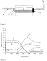
- FIG. 1 processes for deposition of zinc oxide coatings on glass substrates in relation to the present invention were performed using a laboratory scale static coater.
- premixed precursors move towards the coater through a heated line 1 before reaching baffle section 2, which equalises the precursor flow before it enters the sealed coating section.
- the glass substrate 4 sits on a heated carbon block 3 which is heated to the desired temperature using either: heating elements (not shown) inserted inside the carbon block; or, by an induction coil (not shown) around the sealed coating section. Any unreacted precursor or by-products are then directed towards fish tail exhaust 5, and continue towards the incinerator 6.
- the arrows in Figure 1 show the direction in which the gaseous mixture moves.
- Esters including ethyl acetate (EtOAc) and t-butyl acetate (tBuOAc) were found to be efficient oxidants for the process, speeding the reaction and producing thick films, and allowing pre-mixing in the presence of the phosphorus with alkyl zinc compounds without premature pre-reaction or excessive powder formation.
- EtOAc ethyl acetate
- tBuOAc t-butyl acetate
- the precursors were delivered in a nitrogen carrier gas via vessels/bubblers with a total flow rate of about 12 standard litres per minute (slm) to 13 standard litres per minute (slm) (litres min -1 , at standard temperature and pressure, (stp)). Delivery lines were maintained at a temperature of about 150 °C to avoid condensation.
- the substrate for Comparative Example F and Examples 5, 7, 11 and 34 was float glass coated with a transparent conductive oxide having the film sequence: glass/tin oxide, silicon dioxide/fluorine doped tin oxide (glass/SnO 2 /SiO 2 /SnO 2 :F) (available from NSG).
- the substrate for all the other Comparative Examples and Examples was float glass having a coating of silica approximately 25 nm thick.
- the diethyl zinc (DEZ) vessel temperature (°C) was between 67 °C and 75 °C and the DEZ carrier gas flow in litres per minute (L min -1 ) at standard temperature and pressure, (stp) was between 0.44 L min -1 and 0.80 L min -1 .
- the triethyl phosphite (P(OCH 2 CH 3 ) 3 ) was 64 °C or 65 °C and, for the Examples, the triethyl phosphite carrier gas flow rate in litres per minute (L min -1 ) at standard temperature and pressure (stp) was between 0.05 L min -1 and 0.55 L min -1 .
- the oxidant was supplied through a syringe, and the oxidant was injected into a carrier gas having a flow rate of 5.00 L min -1 (at standard temperature and pressure (stp)).
- the thickness of the deposited zinc oxide layer in the examples was determined by examining the interference reflection colour of the coating at the thickest position and estimating the thickness, assuming a refractive index of 1.8.
- the Examples show that a thicker zinc oxide layer is deposited when a phosphorus source, in the form of triethyl phosphite, is added to the precursor mixture compared to the Comparative Examples without triethyl phosphite (when the DEZ amount is the same).
- the thickness of the zinc oxide coating layer obtained also generally increases.
- the quantity of triethyl phosphite required to produce a thickness increase is small with an increase seen at just 2% of the DEZ concentration.
- the amount of triethyl phosphite is increased to 15% of the DEZ concentration, absorption was seen in the zinc oxide coating layer, indicating that the deposition rate was high enough to enable a fully oxidised zinc oxide layer to be produced at the amount of oxidant used. The use of greater amounts of oxidant is likely to lead to a fully oxidised layer.
- the thickness of the zinc oxide layer was determined by looking at the reflection colour.
- the data provided by the examples confirms that a similar improvement in the thickness of the zinc oxide layer is achieved by adding triethyl phosphite when a transparent conductive coated substrate is used as when using a silica coated glass substrate.
- the thickness of the zinc oxide layer (in nm) was estimated based on colour interference fringes seen on the substrate after deposition. Below 70nm, layers (or films) are colourless and the thickness cannot be estimated in the same way.
- the substrate for Comparative Example K and Examples 38, 41, 44 and 47 was float glass coated with a transparent conductive oxide having the sequence: glass/tin oxide, silicon dioxide/fluorine doped tin oxide (glass/SnO 2 /SiO 2 /SnO 2 :F) (available from NSG).
- the substrate for the other Comparative Examples and Examples was float glass having a coating of silica approximately 25 nm thick.
- the diethyl zinc (DEZ) vessel temperature (°C) was between 73 °C and 85 °C, and the DEZ carrier flow in litres per minute (L min -1 ), at standard temperature and pressure (stp) was between 0.63 L min -1 and 1.20 L min -1 .
- the triethyl phosphite vessel temperature (°C) was 64 °C, 65 °C or 69 °C and the triethyl phosphite carrier flow in litres per minute (L min -1 ), for the Examples, was between 0.11 L min -1 and 1.17 L min -1 .
- the oxidant, ethyl acetate (CH 3 COOCH 2 CH 3 ) was supplied through a syringe, injecting the oxidant into a carrier gas at a flow rate of 5.00 L min -1 at standard temperature and pressure (stp).
- the thickness was determined by examining the interference reflection colour of the zinc oxide coating at the thickest position and estimating the thickness assuming a refractive index of 1.8.
- the thickness of the zinc oxide layer was estimated based on the colour interference fringes seen on the substrate after deposition. Below 70nm layers (or films) are colourless and thickness cannot be estimated in the same way.
- XPS X ray photoelectron spectroscopy
- ToF-SIMS Time of Flight Secondary Ion Mass Spectrometry
- the analysis beam was Bi 3+ and the sputter beam was 1keV Cs + with a beam current of 70.2 nA.
- the sputter beam was rastered over a 200 ⁇ 200 ⁇ m area and the bismuth analysis beam was rastered over a 50 ⁇ 50 ⁇ m area at the centre of the sputtered region.
- Example 33 Only Example 33 provided a phosphorus signal response at just above the limit of detection.
- Example 6 Example 33 and Comparative Example E were analysed by SEM.
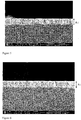
- Example 6 SEM was also used to confirm the thickness of the zinc oxide layer in Example 6, which was found to be 210 - 221 nm, as illustrated in Figure 7 and Figure 8 .
- Example 33 SEM was further used to confirm the thickness of the zinc oxide layer in Example 33, which was found to 286nm, as shown in Figure 9 .
- results and images show that by adding a small amount of triethyl phosphite to the precursor mixture in accordance with the method of the present invention, the thickness of the zinc oxide layer deposited was increased by an amount of from 10 to 15%. In addition, it was found that by adding a larger amount of triethyl phosphite to the precursor mixture in accordance with the method of the present invention the thickness of the zinc oxide layer deposited could be increased by from 39 to 44%.
- Example 6 Example 33 and Comparative Example E were analysed by XRD
- X-ray diffraction was performed using a Bruker D8 Discover X-ray diffractometer using monochromatic Cu K ⁇ 1 and Cu K ⁇ 2 radiation of wavelengths 0.154056 and 0.154439 nm respectively, emitted with a voltage of 40 kV and a current of 40 mA in an intensity ratio of 2:1. Diffraction patterns were obtained by scanning the samples from 5 to 95° 2 ⁇ using an X'Celerator detector, allowing detection of crystalline phases in the first 1 to 10 microns of the sample surface. A scanning time of 1 hour per sample was used.
- the coating in each case exhibited crystalline phases identified as zinc oxide (indexed to Zincite, ZnO, Hexagonal). Information on the XRD results is provided in Tables 6 to 9, below.
- Example 33 The crystallite size was approximately 9 to 18 nm (see Table 6 below). The crystallite size for Example 33 was smaller than that of the other samples. All the samples showed some preferred orientation in the (100) plane. Table 6: Sample Reflection Integral breadth (sample) Integral breadth (std) Peak position (2 ⁇ ) Crystallite size (nm) Comparative Example E (100) 0.646 0.139 31.73 19 (101) 0.608 0.138 36.21 21 (110) 0.992 0.133 56.56 13 Average - - - 18 Example 6 (100) 0.668 0.139 31.75 19 (101) 0.701 0.138 36.23 18 (110) 1.091 0.133 56.56 11 Average - - - 16 Example 33 (100) 1.066 0.139 31.66 11 (101) 1.391 0.138 36.08 8 (110) 1.445 0.133 56.43 8 Average - - - 9
- Table 6 there is provided details of the crystallite size of the zinc oxide layer for Comparative Example 5, Example 6 and Example 33.
- Table 7 ⁇ hkl ⁇ Pos. Meas. d-spacing FWHM Height Rel. Int. Measured Rel. Int. ICDD I/Io (2 ⁇ ) [ ⁇ ] (2 ⁇ ) [cts] [%] [%] (100) 31.73 2.8175 0.45 874 95.7 55.2 1.73 (101) 36.21 2.4788 0.48 913 100.0 100.0 1.00 (110) 56.56 1.6259 0.60 210 22.9 31.4 0.73
- Table 7 details the peak parameters obtained by X-ray diffraction for Comparative Example E.
- Table 8 ⁇ hkl ⁇ Pos. Meas. d-spacing FWHM Height Rel. Int. Measured Rel. Int. ICDD I/Io (2 ⁇ ) [ ⁇ ] (2 ⁇ ) [cts] [%] [%] (100) 31.75 2.8164 0.49 2586 100.0 55.2 1.81 (101) 36.23 2.4776 0.64 424 16.4 100.0 0.16 (110) 56.56 1.6259 0.80 674 26.1 31.4 0.83
- Table 8 details the peak parameters obtained by X-ray diffraction for Example 6.
- Table 9 ⁇ hkl ⁇ Pos. Meas. d-spacing FWHM Height Rel. Int. Measured Rel. Int. ICDD I/Io (2 ⁇ ) [ ⁇ ] (2 ⁇ ) [cts] [%] [%] (100) 31.66 2.8242 0.75 2078 100.0 55.2 1.81 (101) 36.08 2.4875 0.90 271 13.0 100.0 0.13 (110) 56.43 1.6294 1.15 629 30.3 31.4 0.96
- Table 9 details the peak parameters obtained by X-ray diffraction for Example 33.
- TMP trimethyl phosphite
- TIP triisopropyl phosphite
- TEPa triethyl phosphate
- the precursors were delivered in a nitrogen carrier gas via vessels/bubblers with a total flow rate of about 12 standard litres per minute (slm) to 13 standard litres per minute (slm), at standard temperature and pressure, (stp)). Delivery lines were maintained at a temperature in the region of about 150 °C to avoid condensation.
- Example 53, Example 74, and Example 77 were analysed by SEM and XPS. These Examples were chosen because a similar amount of diethyl zinc (DEZ), tertbutylacetate (tBuOAc) and phosphorus precursor were used for the deposition of the zinc oxide layer.
- DEZ diethyl zinc
- tBuOAc tertbutylacetate
- phosphorus precursor phosphorus precursor
- Example 74 provides a baseline example of the deposition of zinc oxide (ZnO) using DEZ and tBuOAc.
- Figure 10 is an x-ray photoelectron spectroscopy (XPS) trace for Example 74.
- Figure 10 illustrates that the film (or layer) deposited comprises zinc atoms and oxygen atoms in the correct stoichiometry for ZnO, and in the absence of any phosphorus atoms. This is to be expected since no phosphorus containing chemicals were involved in the deposition of the zinc oxide layer.
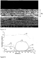
- Figure 11 is a scanning electron micrograph (SEM) image of Example 74, for which the thickness of the zinc oxide layer indicated by distance A, was found to be in the range of 267 - 287nm.
- Example 53 provides a zinc oxide (ZnO) layer deposited using diethyl zinc (DEZ), tertbutylacetate (tBuOAc) and trimethylphosphite (TMP).
- ZnO zinc oxide
- tBuOAc tertbutylacetate
- TMP trimethylphosphite
- Figure 12 is an x-ray photoelectron spectroscopy (XPS) trace of Example 53.
- Figure 12 illustrates again that the coating layer deposited by the method of the present invention comprises zinc (Zn) atoms and oxygen atoms in the correct stoichiometry for ZnO. However, no phosphorus atoms were detected. That is, the results are similar to the results seen when using triethyl phosphite.
- Figure 13 is a scanning electron micrograph (SEM) image of Example 53 confirming the thickness of the zinc oxide layer to be in the range of 292 to 300nm. That is, in Example 53 there was observed an increase in the thickness of the zinc oxide layer of between 4 and 9%, compared to the thickness of the zinc oxide layer in Example 74. Therefore, it can be seen from Example 53 that trimethylphosphite (TMP) may also be used as a phosphorus source in the method of the present invention.
- TMP trimethylphosphite
- Example 77 a zinc oxide coating layer was deposited using diethyl zinc (DEZ), tertbutylacetate (tBuOAc) and triethylphosphate (TEPa).
- Figure 14 is an x-ray photoelectron spectroscopy (XPS) trace of the zinc oxide later of Example 77.
- the x-ray photoelectron spectroscopy (XPS) trace shows again that a zinc oxide film is deposited which comprises zinc atoms and oxygen atoms, in the correct stoichiometry for ZnO, in the absence of any phosphorus atoms. That is, similar results are seen for Example 77 when using triethyl phosphite.
- Figure 15 is an SEM image of Example 77 confirming the thickness of the zinc oxide layer to be in the range of 396 to 406nm. That is, there was an increase in the thickness of the zinc oxide layer in Example 77 of from 41 and 49% compared to the thickness of the zinc oxide layer obtained in Example 74.
- TEPa triethylphosphate
- TIP triisopropyl phosphite
- Table 11 Table 11 provides details of the experiments performed in accordance with the method of the present invention using alternative phosphorus sources in the precursor mixture.
- Example or Comparative Example Phosphorus Precursor Used Reactor Temperature (°C) DEZ Carrier Gas Flow (L/min) DEZ Vessel T (°C) Phosphorus Precursor Carrier Gas Flow (L/min) Phosphorus Precursor Vessel T (°C) Oxidant Supply (cm 3 /hr) Run Time (s) 49 TMP 600 0.58 74.0 0.00 0.0 100.00 30 50 TMP 600 0.61 73.0 0.00 0.0 100.00 30 51 TMP 600 0.64 72.0 0.05 29.0 100.00 30 52 TMP 600 0.64 72.0 0.15 29.0 100.00 30 53* TMP 600 0.64 72.0 0.30 29.0 100.00 30 54* TMP 600 0.64 72.0 0.59 29.0 100.00 30 55* TMP 600 0.64 72.0 0.15 29.0 100.00 30 56 TMP 600 0.68 71.0 0.00 0.0 100.00 30 57 TMP 600 0.64 72.0 0.30 29.0 100.00 30 58 TMP 600 0.70 72.0 0.00 2
- Figure 16 is an x-ray photoelectron spectroscopy (XPS) trace for Example 82.
- Figure 16 illustrates that the layer (film) deposited comprises zinc atoms and oxygen atoms and phosphorus atoms.
- Table 15 provides the stoichiometry of the zinc oxide layer for Example 82 as ZnO:P 0.75
- Figure 17 is x-ray photoelectron spectroscopy (XPS) trace for Example 83.
- Figure 17 illustrates that the film deposited comprises zinc atoms, oxygen atoms and phosphorus atoms.
- Table 15 also provides stoichiometry of the zinc oxide layer for Example 83 as ZnO:P 0.5 .
- Table 15 shows that it is possible to deposit both 'pure' zinc oxide films, that is, zinc oxide film which do not comprise phosphorus, and also phosphorus doped zinc oxide films using triethyl phosphite by the method of the present invention.
- Table 13 Example or Comparative Example (CE) Reactor Temperature (°C) DEZ Carrier Gas Flow (L / min) DEZ vessel T (°C) TEP Carrier Gas Flow (L / min) TEP vessel T (°C) Oxidant Amount (cm 3 / hour) Run Time (s) 82 600 0.64 72.0 1.96 104.0 0.00 30 83 600 0.32 72.0 0.95 105.0 0.00 30
- Table 13 there is illustrated the experimental conditions used for the preparation of examples 82 and 83.
- Table 15 Example or Comparative Example (CE) Average concentration in the coating (atomic %) Zinc (Zn) Oxygen (O) Phosphorus (P) 82 23.6 58.5 17.9 83 29.2 55.8 15.0
- Table 15 there is illustrated the average concentration of each of the elements zinc, oxygen and phosphorus, present in the zinc oxide layer prepared according to the present invention for examples 82 and 83.
- the method of the present invention it is possible to deposit a zinc oxide coating layer atop a float glass substrate.
- the zinc oxide coating may be applied to a layer of silica oxide or tin oxide deposited on the float glass substrate.
- the resultant coated glass may be used in a range of applications, including but not limited to, a photooltaic cell.
- the zinc oxide coating prepared according to the present invention may be deposited over a layer of fluorine doped tin oxide, the fluorine doped tin oxide being part of a transparent conductive coating, applied above a glass substrate such as float glass.
- Figure 18 is a schematic representation of a photovoltaic cell comprising a zinc oxide coating layer 120, applied above a transparent conductive coating (TCO) 110, deposited on a glass substrate, such as float glass 100.
- TCO transparent conductive coating
- photovoltaic material 130 such as for example a cadmium telluride layer 130 may be applied above the zinc oxide layer 120.
Landscapes
- Chemical & Material Sciences (AREA)
- Materials Engineering (AREA)
- Engineering & Computer Science (AREA)
- Chemical Kinetics & Catalysis (AREA)
- General Chemical & Material Sciences (AREA)
- Organic Chemistry (AREA)
- Geochemistry & Mineralogy (AREA)
- Life Sciences & Earth Sciences (AREA)
- Inorganic Chemistry (AREA)
- Mechanical Engineering (AREA)
- Metallurgy (AREA)
- Surface Treatment Of Glass (AREA)
- Chemical Vapour Deposition (AREA)
Claims (14)
- Verfahren zum Abscheiden einer Zinkoxid enthaltenden Beschichtung auf einem Floatglassubstrat in Abwesenheit von getrennten Vorläuferströmen, wobei das Verfahren umfasst:Bereitstellen eines Floatglassubstrats,Bereitstellen eines Vorläufergemischs, das eine Alkylzinkverbindung und eine Phosphorquelle umfasst, wobei die Phosphorquelle eine Verbindung der Formel OnP(OR3)3 umfasst, bei der n 0 oder 1 ist und jedes R3 ein Hydrocarbyl ist, undZuführen des Vorläufergemischs zu einer Oberfläche des Floatglassubstrats, um die Beschichtung aus Zinkoxid während des Floatglas-Herstellungsverfahrens abzuscheiden.
- Verfahren nach Anspruch 1, bei dem das Vorläufergemisch ferner eine Sauerstoffquelle umfasst, die einen Ester, vorzugsweise ein Alkylacetat, umfasst.
- Verfahren nach Anspruch 1 oder Anspruch 2, bei dem die Alkylzinkverbindung Dialkylzink, vorzugsweise Dialkylzink der Formel R1R2Zn, ist, wobei R1 und R2 jeweils unabhängig voneinander unter substituiertem oder unsubstituiertem C1-C4-Alkyl oder Phenyl ausgewählt sind.
- Verfahren nach Anspruch 3, bei dem R1 und R2 jeweils unabhängig voneinander unter Methyl oder Ethyl ausgewählt sind, wobei vorzugsweise R1 und R2 beide Methyl oder beide Ethyl sind.
- Verfahren nach einem der vorhergehenden Ansprüche, bei dem jedes R3 unabhängig unter substituiertem oder unsubstituiertem C1-C4-Alkyl ausgewählt ist, wobei vorzugsweise jedes R3 Propyl, Ethyl oder Methyl ist.
- Verfahren nach Anspruch 2, bei dem der Ester unter einem oder mehreren von Methylacetat, Ethylacetat, Propylacetat, Butylacetat oder einem Gemisch aus zwei oder mehreren dieser Ester ausgewählt ist, wobei der Ester vorzugsweise t-Butylacetat umfasst.
- Verfahren nach einem der vorhergehenden Ansprüche, bei dem das Vorläufergemisch ein gasförmiges Vorläufergemisch ist; und/oder bei dem das Verfahren eine chemische Gasphasenabscheidung bei Atmosphärendruck ist.
- Verfahren nach einem der vorhergehenden Ansprüche, bei dem das Substrat beschichtetes Glas umfasst.
- Verfahren nach einem der vorhergehenden Ansprüche, bei dem die Oberfläche des Substrats eine Temperatur im Bereich von 300 °C bis 800 °C, vorzugsweise 400 °C bis 750 °C, weiter bevorzugt 410 °C bis 750 °C, am meisten bevorzugt 470 °C bis 750 °C aufweist.
- Verfahren nach Anspruch 9, bei dem die Oberfläche des Substrats eine Temperatur im Bereich von 580 °C bis 650 °C aufweist.
- Verfahren nach Anspruch 1, bei dem die Zinkoxid umfassende Beschichtung abgeschieden wird, während sich das Band aus Floatglas im Floatbad befindet.
- Verfahren nach Anspruch 8, bei dem das beschichtete Glassubstrat eine auf dem Glassubstrat abgeschiedene Siliziumdioxid- oder Zinnoxidbeschichtung umfasst; und bei dem die Zinkoxidbeschichtung über der Siliziumdioxid- oder Zinnoxidbeschichtung abgeschieden wird.
- Verfahren nach Anspruch 8, bei dem das beschichtete Glassubstrat zur Verwendung in einer photovoltaischen Zelle geeignet ist und eine auf dem Glassubstrat abgeschiedene, mit Fluor dotierte Zinnoxidbeschichtung umfasst; und bei dem die Zinkoxidbeschichtung über der mit Fluor dotierten Zinnoxidbeschichtung abgeschieden wird.
- Verwendung eines Vorläufergemischs für die chemische Gasphasenabscheidung in dem Verfahren nach einem der Ansprüche 1 bis 13, welches eine Alkylzinkverbindung, eine Phosphorquelle und optional einen Ester umfasst, wobei die Phosphorquelle eine Verbindung der Formel OnP(OR3)3 umfasst, wobei n 0 oder 1 ist und jedes R3 Hydrocarbyl ist.
Applications Claiming Priority (2)
| Application Number | Priority Date | Filing Date | Title |
|---|---|---|---|
| GBGB1521165.9A GB201521165D0 (en) | 2015-12-01 | 2015-12-01 | Method for depositing a coating |
| PCT/GB2016/053781 WO2017093739A1 (en) | 2015-12-01 | 2016-12-01 | Method for depositing a coating |
Publications (2)
| Publication Number | Publication Date |
|---|---|
| EP3384064A1 EP3384064A1 (de) | 2018-10-10 |
| EP3384064B1 true EP3384064B1 (de) | 2021-05-12 |
Family
ID=55177505
Family Applications (1)
| Application Number | Title | Priority Date | Filing Date |
|---|---|---|---|
| EP16808769.0A Active EP3384064B1 (de) | 2015-12-01 | 2016-12-01 | Verfahren zur abscheidung einer beschichtung |
Country Status (4)
| Country | Link |
|---|---|
| US (2) | US20180346374A1 (de) |
| EP (1) | EP3384064B1 (de) |
| GB (1) | GB201521165D0 (de) |
| WO (1) | WO2017093739A1 (de) |
Family Cites Families (8)
| Publication number | Priority date | Publication date | Assignee | Title |
|---|---|---|---|---|
| US5356718A (en) | 1993-02-16 | 1994-10-18 | Ppg Industries, Inc. | Coating apparatus, method of coating glass, compounds and compositions for coating glasss and coated glass substrates |
| GB9616983D0 (en) | 1996-08-13 | 1996-09-25 | Pilkington Plc | Method for depositing tin oxide and titanium oxide coatings on flat glass and the resulting coated glass |
| GB9710547D0 (en) * | 1997-05-23 | 1997-07-16 | Pilkington Plc | Coating method |
| US20050221003A1 (en) * | 2004-03-31 | 2005-10-06 | Remington Michael P Jr | Enhancement of SiO2 deposition using phosphorus (V) compounds |
| GB0518383D0 (en) * | 2005-09-09 | 2005-10-19 | Pilkington Plc | Deposition process |
| JP2007234996A (ja) | 2006-03-02 | 2007-09-13 | Kaneka Corp | 薄膜太陽電池の製造方法、及び、薄膜太陽電池。 |
| US9776914B2 (en) * | 2012-03-16 | 2017-10-03 | Pilkington Group Limited | Chemical vapor deposition process for depositing zinc oxide coatings, method for forming a conductive glass article and the coated glass articles produced thereby |
| GB201409135D0 (en) | 2014-05-22 | 2014-07-09 | Pilkington Group Ltd | Deposition of zinc oxysulphide by CVD |
-
2015
- 2015-12-01 GB GBGB1521165.9A patent/GB201521165D0/en not_active Ceased
-
2016
- 2016-12-01 US US15/780,259 patent/US20180346374A1/en not_active Abandoned
- 2016-12-01 EP EP16808769.0A patent/EP3384064B1/de active Active
- 2016-12-01 WO PCT/GB2016/053781 patent/WO2017093739A1/en not_active Ceased
-
2021
- 2021-11-15 US US17/526,137 patent/US11945746B2/en active Active
Also Published As
| Publication number | Publication date |
|---|---|
| WO2017093739A1 (en) | 2017-06-08 |
| GB201521165D0 (en) | 2016-01-13 |
| US20220073419A1 (en) | 2022-03-10 |
| US20180346374A1 (en) | 2018-12-06 |
| EP3384064A1 (de) | 2018-10-10 |
| US11945746B2 (en) | 2024-04-02 |
Similar Documents
| Publication | Publication Date | Title |
|---|---|---|
| JP6334782B2 (ja) | ガラス基板上にシリカコーティングを形成するプロセス | |
| Salami et al. | Atomic layer deposition of ultrathin indium oxide and indium tin oxide films using a trimethylindium, tetrakis (dimethylamino) tin, and ozone precursor system | |
| US20110206846A1 (en) | Method for depositing transparent conducting oxides | |
| EP2817433B1 (de) | Verfahren zur chemischen dampfabscheidung von siliciumdioxid auf einem glassubstrat | |
| KR101473024B1 (ko) | 아연 산화물 코팅 물품의 저온 제조 방법 | |
| TW201313946A (zh) | 藉由大氣壓化學氣相沉積來沉積氧化矽 | |
| AU2010306798A1 (en) | Deposition of doped ZnO films on polymer substrates by UV-assisted chemical vapor deposition | |
| US6696700B2 (en) | P-type transparent copper-aluminum-oxide semiconductor | |
| AU2006288933B2 (en) | Deposition process | |
| US11945746B2 (en) | Method for depositing a coating | |
| WO2006054730A1 (ja) | 薄膜付きガラス板の製造方法 | |
| Ciliberto et al. | Synthesis of aluminum oxide thin films: Use of aluminum tris‐dipivaloylmethanate as a new low pressure metal organic chemical vapor deposition precursor | |
| Malandrino et al. | Effects of processing parameters in the MOCVD growth of nanostructured lanthanum trifluoride and oxyfluoride thin films | |
| JP2002522336A (ja) | ガラスの被覆方法 | |
| US20110086235A1 (en) | Methods of nucleation control in film deposition | |
| EP1730087B1 (de) | Verfahren zur abscheidung von aluminiumoxidbeschichtungen | |
| GB2512069A (en) | Aluminium doped tin oxide coatings | |
| EP3191423B1 (de) | Verfahren zur gasphasenabscheidung einer titanoxidbeschichtung | |
| JP4683525B2 (ja) | 透明導電膜、及び透明導電膜形成材料 | |
| Choi | Effects of seed layer and thermal treatment on atomic layer deposition-grown tin oxide | |
| JP6875992B2 (ja) | 析出方法 | |
| JP2025519102A (ja) | コーティングを形成する方法 | |
| Johnson et al. | Atmospheric Pressure Plasma Deposition of Transparent Conductors-Tailoring Precursor Chemistries |
Legal Events
| Date | Code | Title | Description |
|---|---|---|---|
| STAA | Information on the status of an ep patent application or granted ep patent |
Free format text: STATUS: UNKNOWN |
|
| STAA | Information on the status of an ep patent application or granted ep patent |
Free format text: STATUS: THE INTERNATIONAL PUBLICATION HAS BEEN MADE |
|
| PUAI | Public reference made under article 153(3) epc to a published international application that has entered the european phase |
Free format text: ORIGINAL CODE: 0009012 |
|
| STAA | Information on the status of an ep patent application or granted ep patent |
Free format text: STATUS: REQUEST FOR EXAMINATION WAS MADE |
|
| 17P | Request for examination filed |
Effective date: 20180702 |
|
| AK | Designated contracting states |
Kind code of ref document: A1 Designated state(s): AL AT BE BG CH CY CZ DE DK EE ES FI FR GB GR HR HU IE IS IT LI LT LU LV MC MK MT NL NO PL PT RO RS SE SI SK SM TR |
|
| AX | Request for extension of the european patent |
Extension state: BA ME |
|
| DAV | Request for validation of the european patent (deleted) | ||
| DAX | Request for extension of the european patent (deleted) | ||
| GRAP | Despatch of communication of intention to grant a patent |
Free format text: ORIGINAL CODE: EPIDOSNIGR1 |
|
| STAA | Information on the status of an ep patent application or granted ep patent |
Free format text: STATUS: GRANT OF PATENT IS INTENDED |
|
| RIC1 | Information provided on ipc code assigned before grant |
Ipc: C23C 16/40 20060101AFI20201028BHEP Ipc: C03C 17/34 20060101ALI20201028BHEP Ipc: C03C 17/245 20060101ALI20201028BHEP Ipc: C03C 17/00 20060101ALI20201028BHEP |
|
| INTG | Intention to grant announced |
Effective date: 20201201 |
|
| GRAS | Grant fee paid |
Free format text: ORIGINAL CODE: EPIDOSNIGR3 |
|
| GRAA | (expected) grant |
Free format text: ORIGINAL CODE: 0009210 |
|
| STAA | Information on the status of an ep patent application or granted ep patent |
Free format text: STATUS: THE PATENT HAS BEEN GRANTED |
|
| AK | Designated contracting states |
Kind code of ref document: B1 Designated state(s): AL AT BE BG CH CY CZ DE DK EE ES FI FR GB GR HR HU IE IS IT LI LT LU LV MC MK MT NL NO PL PT RO RS SE SI SK SM TR |
|
| REG | Reference to a national code |
Ref country code: GB Ref legal event code: FG4D |
|
| REG | Reference to a national code |
Ref country code: CH Ref legal event code: EP |
|
| REG | Reference to a national code |
Ref country code: DE Ref legal event code: R096 Ref document number: 602016057811 Country of ref document: DE |
|
| REG | Reference to a national code |
Ref country code: IE Ref legal event code: FG4D |
|
| REG | Reference to a national code |
Ref country code: AT Ref legal event code: REF Ref document number: 1392222 Country of ref document: AT Kind code of ref document: T Effective date: 20210615 |
|
| REG | Reference to a national code |
Ref country code: LT Ref legal event code: MG9D |
|
| REG | Reference to a national code |
Ref country code: AT Ref legal event code: MK05 Ref document number: 1392222 Country of ref document: AT Kind code of ref document: T Effective date: 20210512 |
|
| REG | Reference to a national code |
Ref country code: NL Ref legal event code: MP Effective date: 20210512 |
|
| PG25 | Lapsed in a contracting state [announced via postgrant information from national office to epo] |
Ref country code: LT Free format text: LAPSE BECAUSE OF FAILURE TO SUBMIT A TRANSLATION OF THE DESCRIPTION OR TO PAY THE FEE WITHIN THE PRESCRIBED TIME-LIMIT Effective date: 20210512 Ref country code: FI Free format text: LAPSE BECAUSE OF FAILURE TO SUBMIT A TRANSLATION OF THE DESCRIPTION OR TO PAY THE FEE WITHIN THE PRESCRIBED TIME-LIMIT Effective date: 20210512 Ref country code: BG Free format text: LAPSE BECAUSE OF FAILURE TO SUBMIT A TRANSLATION OF THE DESCRIPTION OR TO PAY THE FEE WITHIN THE PRESCRIBED TIME-LIMIT Effective date: 20210812 Ref country code: AT Free format text: LAPSE BECAUSE OF FAILURE TO SUBMIT A TRANSLATION OF THE DESCRIPTION OR TO PAY THE FEE WITHIN THE PRESCRIBED TIME-LIMIT Effective date: 20210512 Ref country code: HR Free format text: LAPSE BECAUSE OF FAILURE TO SUBMIT A TRANSLATION OF THE DESCRIPTION OR TO PAY THE FEE WITHIN THE PRESCRIBED TIME-LIMIT Effective date: 20210512 |
|
| PG25 | Lapsed in a contracting state [announced via postgrant information from national office to epo] |
Ref country code: RS Free format text: LAPSE BECAUSE OF FAILURE TO SUBMIT A TRANSLATION OF THE DESCRIPTION OR TO PAY THE FEE WITHIN THE PRESCRIBED TIME-LIMIT Effective date: 20210512 Ref country code: SE Free format text: LAPSE BECAUSE OF FAILURE TO SUBMIT A TRANSLATION OF THE DESCRIPTION OR TO PAY THE FEE WITHIN THE PRESCRIBED TIME-LIMIT Effective date: 20210512 Ref country code: NO Free format text: LAPSE BECAUSE OF FAILURE TO SUBMIT A TRANSLATION OF THE DESCRIPTION OR TO PAY THE FEE WITHIN THE PRESCRIBED TIME-LIMIT Effective date: 20210812 Ref country code: PL Free format text: LAPSE BECAUSE OF FAILURE TO SUBMIT A TRANSLATION OF THE DESCRIPTION OR TO PAY THE FEE WITHIN THE PRESCRIBED TIME-LIMIT Effective date: 20210512 Ref country code: PT Free format text: LAPSE BECAUSE OF FAILURE TO SUBMIT A TRANSLATION OF THE DESCRIPTION OR TO PAY THE FEE WITHIN THE PRESCRIBED TIME-LIMIT Effective date: 20210913 Ref country code: IS Free format text: LAPSE BECAUSE OF FAILURE TO SUBMIT A TRANSLATION OF THE DESCRIPTION OR TO PAY THE FEE WITHIN THE PRESCRIBED TIME-LIMIT Effective date: 20210912 Ref country code: GR Free format text: LAPSE BECAUSE OF FAILURE TO SUBMIT A TRANSLATION OF THE DESCRIPTION OR TO PAY THE FEE WITHIN THE PRESCRIBED TIME-LIMIT Effective date: 20210813 Ref country code: LV Free format text: LAPSE BECAUSE OF FAILURE TO SUBMIT A TRANSLATION OF THE DESCRIPTION OR TO PAY THE FEE WITHIN THE PRESCRIBED TIME-LIMIT Effective date: 20210512 |
|
| PG25 | Lapsed in a contracting state [announced via postgrant information from national office to epo] |
Ref country code: NL Free format text: LAPSE BECAUSE OF FAILURE TO SUBMIT A TRANSLATION OF THE DESCRIPTION OR TO PAY THE FEE WITHIN THE PRESCRIBED TIME-LIMIT Effective date: 20210512 |
|
| PG25 | Lapsed in a contracting state [announced via postgrant information from national office to epo] |
Ref country code: RO Free format text: LAPSE BECAUSE OF FAILURE TO SUBMIT A TRANSLATION OF THE DESCRIPTION OR TO PAY THE FEE WITHIN THE PRESCRIBED TIME-LIMIT Effective date: 20210512 Ref country code: ES Free format text: LAPSE BECAUSE OF FAILURE TO SUBMIT A TRANSLATION OF THE DESCRIPTION OR TO PAY THE FEE WITHIN THE PRESCRIBED TIME-LIMIT Effective date: 20210512 Ref country code: EE Free format text: LAPSE BECAUSE OF FAILURE TO SUBMIT A TRANSLATION OF THE DESCRIPTION OR TO PAY THE FEE WITHIN THE PRESCRIBED TIME-LIMIT Effective date: 20210512 Ref country code: CZ Free format text: LAPSE BECAUSE OF FAILURE TO SUBMIT A TRANSLATION OF THE DESCRIPTION OR TO PAY THE FEE WITHIN THE PRESCRIBED TIME-LIMIT Effective date: 20210512 Ref country code: DK Free format text: LAPSE BECAUSE OF FAILURE TO SUBMIT A TRANSLATION OF THE DESCRIPTION OR TO PAY THE FEE WITHIN THE PRESCRIBED TIME-LIMIT Effective date: 20210512 Ref country code: SM Free format text: LAPSE BECAUSE OF FAILURE TO SUBMIT A TRANSLATION OF THE DESCRIPTION OR TO PAY THE FEE WITHIN THE PRESCRIBED TIME-LIMIT Effective date: 20210512 Ref country code: SK Free format text: LAPSE BECAUSE OF FAILURE TO SUBMIT A TRANSLATION OF THE DESCRIPTION OR TO PAY THE FEE WITHIN THE PRESCRIBED TIME-LIMIT Effective date: 20210512 |
|
| REG | Reference to a national code |
Ref country code: DE Ref legal event code: R097 Ref document number: 602016057811 Country of ref document: DE |
|
| PLBE | No opposition filed within time limit |
Free format text: ORIGINAL CODE: 0009261 |
|
| STAA | Information on the status of an ep patent application or granted ep patent |
Free format text: STATUS: NO OPPOSITION FILED WITHIN TIME LIMIT |
|
| 26N | No opposition filed |
Effective date: 20220215 |
|
| PG25 | Lapsed in a contracting state [announced via postgrant information from national office to epo] |
Ref country code: IS Free format text: LAPSE BECAUSE OF FAILURE TO SUBMIT A TRANSLATION OF THE DESCRIPTION OR TO PAY THE FEE WITHIN THE PRESCRIBED TIME-LIMIT Effective date: 20210912 Ref country code: AL Free format text: LAPSE BECAUSE OF FAILURE TO SUBMIT A TRANSLATION OF THE DESCRIPTION OR TO PAY THE FEE WITHIN THE PRESCRIBED TIME-LIMIT Effective date: 20210512 |
|
| PG25 | Lapsed in a contracting state [announced via postgrant information from national office to epo] |
Ref country code: MC Free format text: LAPSE BECAUSE OF FAILURE TO SUBMIT A TRANSLATION OF THE DESCRIPTION OR TO PAY THE FEE WITHIN THE PRESCRIBED TIME-LIMIT Effective date: 20210512 Ref country code: IT Free format text: LAPSE BECAUSE OF FAILURE TO SUBMIT A TRANSLATION OF THE DESCRIPTION OR TO PAY THE FEE WITHIN THE PRESCRIBED TIME-LIMIT Effective date: 20210512 |
|
| REG | Reference to a national code |
Ref country code: CH Ref legal event code: PL |
|
| PG25 | Lapsed in a contracting state [announced via postgrant information from national office to epo] |
Ref country code: LU Free format text: LAPSE BECAUSE OF NON-PAYMENT OF DUE FEES Effective date: 20211201 Ref country code: IE Free format text: LAPSE BECAUSE OF NON-PAYMENT OF DUE FEES Effective date: 20211201 |
|
| PG25 | Lapsed in a contracting state [announced via postgrant information from national office to epo] |
Ref country code: LI Free format text: LAPSE BECAUSE OF NON-PAYMENT OF DUE FEES Effective date: 20211231 Ref country code: CH Free format text: LAPSE BECAUSE OF NON-PAYMENT OF DUE FEES Effective date: 20211231 |
|
| PG25 | Lapsed in a contracting state [announced via postgrant information from national office to epo] |
Ref country code: HU Free format text: LAPSE BECAUSE OF FAILURE TO SUBMIT A TRANSLATION OF THE DESCRIPTION OR TO PAY THE FEE WITHIN THE PRESCRIBED TIME-LIMIT; INVALID AB INITIO Effective date: 20161201 |
|
| P01 | Opt-out of the competence of the unified patent court (upc) registered |
Effective date: 20230507 |
|
| PG25 | Lapsed in a contracting state [announced via postgrant information from national office to epo] |
Ref country code: CY Free format text: LAPSE BECAUSE OF FAILURE TO SUBMIT A TRANSLATION OF THE DESCRIPTION OR TO PAY THE FEE WITHIN THE PRESCRIBED TIME-LIMIT Effective date: 20210512 |
|
| PG25 | Lapsed in a contracting state [announced via postgrant information from national office to epo] |
Ref country code: MK Free format text: LAPSE BECAUSE OF FAILURE TO SUBMIT A TRANSLATION OF THE DESCRIPTION OR TO PAY THE FEE WITHIN THE PRESCRIBED TIME-LIMIT Effective date: 20210512 |
|
| PG25 | Lapsed in a contracting state [announced via postgrant information from national office to epo] |
Ref country code: MT Free format text: LAPSE BECAUSE OF FAILURE TO SUBMIT A TRANSLATION OF THE DESCRIPTION OR TO PAY THE FEE WITHIN THE PRESCRIBED TIME-LIMIT Effective date: 20210512 |
|
| PGFP | Annual fee paid to national office [announced via postgrant information from national office to epo] |
Ref country code: DE Payment date: 20241216 Year of fee payment: 9 |
|
| PGFP | Annual fee paid to national office [announced via postgrant information from national office to epo] |
Ref country code: GB Payment date: 20251218 Year of fee payment: 10 |
|
| PGFP | Annual fee paid to national office [announced via postgrant information from national office to epo] |
Ref country code: FR Payment date: 20251218 Year of fee payment: 10 |
|
| PGFP | Annual fee paid to national office [announced via postgrant information from national office to epo] |
Ref country code: TR Payment date: 20251206 Year of fee payment: 10 Ref country code: BE Payment date: 20251218 Year of fee payment: 10 |