EP3383609B1 - Mischerlöffel - Google Patents
Mischerlöffel Download PDFInfo
- Publication number
- EP3383609B1 EP3383609B1 EP16810474.3A EP16810474A EP3383609B1 EP 3383609 B1 EP3383609 B1 EP 3383609B1 EP 16810474 A EP16810474 A EP 16810474A EP 3383609 B1 EP3383609 B1 EP 3383609B1
- Authority
- EP
- European Patent Office
- Prior art keywords
- opening
- bucket
- funnel
- bucket according
- hopper
- Prior art date
- Legal status (The legal status is an assumption and is not a legal conclusion. Google has not performed a legal analysis and makes no representation as to the accuracy of the status listed.)
- Active
Links
Images


Classifications
-
- B—PERFORMING OPERATIONS; TRANSPORTING
- B28—WORKING CEMENT, CLAY, OR STONE
- B28C—PREPARING CLAY; PRODUCING MIXTURES CONTAINING CLAY OR CEMENTITIOUS MATERIAL, e.g. PLASTER
- B28C5/00—Apparatus or methods for producing mixtures of cement with other substances, e.g. slurries, mortars, porous or fibrous compositions
- B28C5/08—Apparatus or methods for producing mixtures of cement with other substances, e.g. slurries, mortars, porous or fibrous compositions using driven mechanical means affecting the mixing
- B28C5/10—Mixing in containers not actuated to effect the mixing
- B28C5/12—Mixing in containers not actuated to effect the mixing with stirrers sweeping through the materials, e.g. with incorporated feeding or discharging means or with oscillating stirrers
- B28C5/14—Mixing in containers not actuated to effect the mixing with stirrers sweeping through the materials, e.g. with incorporated feeding or discharging means or with oscillating stirrers the stirrers having motion about a horizontal or substantially horizontal axis
- B28C5/141—Mixing in containers not actuated to effect the mixing with stirrers sweeping through the materials, e.g. with incorporated feeding or discharging means or with oscillating stirrers the stirrers having motion about a horizontal or substantially horizontal axis with container tiltable or elevatable for emptying
-
- B—PERFORMING OPERATIONS; TRANSPORTING
- B01—PHYSICAL OR CHEMICAL PROCESSES OR APPARATUS IN GENERAL
- B01F—MIXING, e.g. DISSOLVING, EMULSIFYING OR DISPERSING
- B01F27/00—Mixers with rotary stirring devices in fixed receptacles; Kneaders
- B01F27/05—Stirrers
- B01F27/11—Stirrers characterised by the configuration of the stirrers
- B01F27/112—Stirrers characterised by the configuration of the stirrers with arms, paddles, vanes or blades
- B01F27/1122—Stirrers characterised by the configuration of the stirrers with arms, paddles, vanes or blades anchor-shaped
-
- B—PERFORMING OPERATIONS; TRANSPORTING
- B01—PHYSICAL OR CHEMICAL PROCESSES OR APPARATUS IN GENERAL
- B01F—MIXING, e.g. DISSOLVING, EMULSIFYING OR DISPERSING
- B01F27/00—Mixers with rotary stirring devices in fixed receptacles; Kneaders
- B01F27/60—Mixers with rotary stirring devices in fixed receptacles; Kneaders with stirrers rotating about a horizontal or inclined axis
- B01F27/70—Mixers with rotary stirring devices in fixed receptacles; Kneaders with stirrers rotating about a horizontal or inclined axis with paddles, blades or arms
-
- B—PERFORMING OPERATIONS; TRANSPORTING
- B01—PHYSICAL OR CHEMICAL PROCESSES OR APPARATUS IN GENERAL
- B01F—MIXING, e.g. DISSOLVING, EMULSIFYING OR DISPERSING
- B01F33/00—Other mixers; Mixing plants; Combinations of mixers
- B01F33/50—Movable or transportable mixing devices or plants
- B01F33/501—Movable mixing devices, i.e. readily shifted or displaced from one place to another, e.g. portable during use
- B01F33/5013—Movable mixing devices, i.e. readily shifted or displaced from one place to another, e.g. portable during use movable by mechanical means, e.g. hoisting systems, grippers or lift trucks
-
- B—PERFORMING OPERATIONS; TRANSPORTING
- B01—PHYSICAL OR CHEMICAL PROCESSES OR APPARATUS IN GENERAL
- B01F—MIXING, e.g. DISSOLVING, EMULSIFYING OR DISPERSING
- B01F35/00—Accessories for mixers; Auxiliary operations or auxiliary devices; Parts or details of general application
- B01F35/45—Closures or doors specially adapted for mixing receptacles; Operating mechanisms therefor
- B01F35/452—Closures or doors specially adapted for mixing receptacles; Operating mechanisms therefor by moving them in the plane of the opening
-
- B—PERFORMING OPERATIONS; TRANSPORTING
- B01—PHYSICAL OR CHEMICAL PROCESSES OR APPARATUS IN GENERAL
- B01F—MIXING, e.g. DISSOLVING, EMULSIFYING OR DISPERSING
- B01F35/00—Accessories for mixers; Auxiliary operations or auxiliary devices; Parts or details of general application
- B01F35/45—Closures or doors specially adapted for mixing receptacles; Operating mechanisms therefor
- B01F35/454—Moving covers on a cylindrical drum in a circular path along the drum
-
- B—PERFORMING OPERATIONS; TRANSPORTING
- B01—PHYSICAL OR CHEMICAL PROCESSES OR APPARATUS IN GENERAL
- B01F—MIXING, e.g. DISSOLVING, EMULSIFYING OR DISPERSING
- B01F35/00—Accessories for mixers; Auxiliary operations or auxiliary devices; Parts or details of general application
- B01F35/75—Discharge mechanisms
- B01F35/751—Discharging by opening a gate, e.g. using discharge paddles
-
- B—PERFORMING OPERATIONS; TRANSPORTING
- B01—PHYSICAL OR CHEMICAL PROCESSES OR APPARATUS IN GENERAL
- B01F—MIXING, e.g. DISSOLVING, EMULSIFYING OR DISPERSING
- B01F35/00—Accessories for mixers; Auxiliary operations or auxiliary devices; Parts or details of general application
- B01F35/75—Discharge mechanisms
- B01F35/754—Discharge mechanisms characterised by the means for discharging the components from the mixer
- B01F35/75415—Discharge mechanisms characterised by the means for discharging the components from the mixer using gravity
-
- B—PERFORMING OPERATIONS; TRANSPORTING
- B28—WORKING CEMENT, CLAY, OR STONE
- B28C—PREPARING CLAY; PRODUCING MIXTURES CONTAINING CLAY OR CEMENTITIOUS MATERIAL, e.g. PLASTER
- B28C5/00—Apparatus or methods for producing mixtures of cement with other substances, e.g. slurries, mortars, porous or fibrous compositions
- B28C5/08—Apparatus or methods for producing mixtures of cement with other substances, e.g. slurries, mortars, porous or fibrous compositions using driven mechanical means affecting the mixing
- B28C5/0887—Apparatus or methods for producing mixtures of cement with other substances, e.g. slurries, mortars, porous or fibrous compositions using driven mechanical means affecting the mixing provided with sieves or filters
-
- B—PERFORMING OPERATIONS; TRANSPORTING
- B28—WORKING CEMENT, CLAY, OR STONE
- B28C—PREPARING CLAY; PRODUCING MIXTURES CONTAINING CLAY OR CEMENTITIOUS MATERIAL, e.g. PLASTER
- B28C5/00—Apparatus or methods for producing mixtures of cement with other substances, e.g. slurries, mortars, porous or fibrous compositions
- B28C5/08—Apparatus or methods for producing mixtures of cement with other substances, e.g. slurries, mortars, porous or fibrous compositions using driven mechanical means affecting the mixing
- B28C5/0893—Mobile mixing devices, e.g. hanging
-
- B—PERFORMING OPERATIONS; TRANSPORTING
- B28—WORKING CEMENT, CLAY, OR STONE
- B28C—PREPARING CLAY; PRODUCING MIXTURES CONTAINING CLAY OR CEMENTITIOUS MATERIAL, e.g. PLASTER
- B28C5/00—Apparatus or methods for producing mixtures of cement with other substances, e.g. slurries, mortars, porous or fibrous compositions
- B28C5/08—Apparatus or methods for producing mixtures of cement with other substances, e.g. slurries, mortars, porous or fibrous compositions using driven mechanical means affecting the mixing
- B28C5/10—Mixing in containers not actuated to effect the mixing
- B28C5/12—Mixing in containers not actuated to effect the mixing with stirrers sweeping through the materials, e.g. with incorporated feeding or discharging means or with oscillating stirrers
- B28C5/14—Mixing in containers not actuated to effect the mixing with stirrers sweeping through the materials, e.g. with incorporated feeding or discharging means or with oscillating stirrers the stirrers having motion about a horizontal or substantially horizontal axis
- B28C5/142—Mixing in containers not actuated to effect the mixing with stirrers sweeping through the materials, e.g. with incorporated feeding or discharging means or with oscillating stirrers the stirrers having motion about a horizontal or substantially horizontal axis the stirrer shaft carrying screw-blades
-
- B—PERFORMING OPERATIONS; TRANSPORTING
- B28—WORKING CEMENT, CLAY, OR STONE
- B28C—PREPARING CLAY; PRODUCING MIXTURES CONTAINING CLAY OR CEMENTITIOUS MATERIAL, e.g. PLASTER
- B28C7/00—Controlling the operation of apparatus for producing mixtures of clay or cement with other substances; Supplying or proportioning the ingredients for mixing clay or cement with other substances; Discharging the mixture
- B28C7/16—Discharge means, e.g. with intermediate storage of fresh concrete
-
- E—FIXED CONSTRUCTIONS
- E02—HYDRAULIC ENGINEERING; FOUNDATIONS; SOIL SHIFTING
- E02F—DREDGING; SOIL-SHIFTING
- E02F3/00—Dredgers; Soil-shifting machines
- E02F3/04—Dredgers; Soil-shifting machines mechanically-driven
- E02F3/28—Dredgers; Soil-shifting machines mechanically-driven with digging tools mounted on a dipper- or bucket-arm, i.e. there is either one arm or a pair of arms, e.g. dippers, buckets
- E02F3/36—Component parts
- E02F3/40—Dippers; Buckets ; Grab devices, e.g. manufacturing processes for buckets, form, geometry or material of buckets
- E02F3/407—Dippers; Buckets ; Grab devices, e.g. manufacturing processes for buckets, form, geometry or material of buckets with ejecting or other unloading device
- E02F3/4075—Dump doors; Control thereof
-
- E—FIXED CONSTRUCTIONS
- E02—HYDRAULIC ENGINEERING; FOUNDATIONS; SOIL SHIFTING
- E02F—DREDGING; SOIL-SHIFTING
- E02F7/00—Equipment for conveying or separating excavated material
- E02F7/06—Delivery chutes or screening plants or mixing plants mounted on dredgers or excavators
Definitions
- the present invention relates to a mixer bucket.
- the present invention relates to a mixer bucket that can be actuated by means of an articulated arm of an earthwork machine.
- the present invention relates to a mixer bucket that is so designed as to be actuated by means of an articulated arm of an earthwork machine and is usable to produce cement and supply it safely through an opening provided centrally in the same mixer bucket.
- Mixer buckets are usually tools that, coupled to the ends of the arms of an excavator, allow to produce concrete after having taken sand from a deposit, having positioned the bucket with the mouth thereof facing upwards, so that it can be assimilated to a hopper, having inserted inside it cement and water, and any other ingredients necessary to obtain a concrete of given composition, and having mixed all the ingredients by means of an Archimedes' screw contained inside the bucket.
- the bottom of the bucket has an opening for concrete discharge, arranged centrally, and is suitable to couple with a funnel-shaped member that, in turn, carries a discharging channel.
- a funnel-shaped member that, in turn, carries a discharging channel.
- the bucket shall be raised and maintained in a position of maximal height so as to allow an operator to position the funnel-shaped member below it, i.e. to connect the funnel-shaped member to the bucket, in correspondence of the opening.
- This operation is particularly dangerous due to the instability of the bucket in this position, often resulting in discharging the concrete onto the operator, with sometimes fatal consequences.
- the present invention relates to a mixer bucket.
- the present invention relates to a mixer bucket that can be actuated by means of an articulated arm of an earthwork machine.
- the present invention relates to a mixer bucket that is so designed as to be actuated by means of an articulated arm of an earthwork machine and is usable to produce cement and supply it safely through an opening provided centrally in the same mixer bucket.
- An object of the present invention is to provide a mixer bucket which is safe and practical to be used, which overcomes the limits of the known mixer buckets and can be produced at limited costs.
- a mixer bucket is provided, whose main features will be described in at least one of the appended claims.
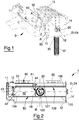
- number 1 indicates, in its entirety, a mixer bucket for an excavator, known and therefore not shown.
- the bucket 1 can be validly used to produce concrete in a safely way once the bucket has been filled with the necessary ingredients and has been adequately positioned, i.e. with an opening thereof arranged horizontal from the arms B of the excavator, as better described below.
- the bucket 1 comprises a casing 10 provided with a hopper 12 extending in a given direction D, is closed at the top by means of a grid 13 and is delimited by a first flank 14 and by a second flank 16 aligned with the direction D and, therefore, facing each other.
- the flanks 14 and 16 are provided with rotatable supports for a shaft 20, which is directed parallel to the direction D and is provided with a plurality of mixing members realized by means of blades 22 arranged along the corresponding axis 24 and angularly displaced so as to mix a mixture of granular components and water contained in the hopper 12.
- the hopper has a concave bottom portion 120 provided with a grid-shaped opening 122 arranged centrally between the first and the second flanks 14 and 16 that therefore subdivides the bottom portion 120 into a first continuous portions 124 and a second continuous portion 126, which are symmetrical and substantially identical, and closed, as shown in figures 2 , 3 , and 5 .
- An actuating unit 11 is associated with the hopper 12, the actuating unit being externally coupled to the flank 16 (or indifferently to the flank 14) and designed to drive the shaft 20 into rotation.
- the hopper 12 carries, through the concave portion 120, a guide 128 aligned with the given direction D.
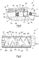
- a slide 127 is coupled to the guide 128 in a freely sliding manner, the slide 127 being shaped in a conjugated manner with the opening 122 and being so designed as to couple in a releasable manner with a funnel-shaped member 30.
- the slide 127 (and therefore the funnel-shaped member 30) couples in a freely translatable manner to the bottom portion 120 along the direction D so as to define a mixture discharging portion that can be positioned at will along the bottom portion 120 and, therefore, selectively facing the opening 122 or facing one of the two continuous portions 124 and 126 (in particular facing the continuous portion 124 in figures 2 , 3 and 5 ).
- an actuating device 40 is carried by the hopper 12 to move the slide 127, and therefore the funnel-shaped member 30 together with a corresponding concrete discharge channel 32, along the guide 128 between a first position P1 ( figure 2 ), where it faces the opening 122, and a second position P2 ( figure 5 ), lateral with respect to the opening 122 on the side of the flank 14.
- the bucket 1 comprises a closing unit 50 associated with the slide 127 in a rigid manner, aligned with the direction D in order to close selectively the opening 30 when, in use, the funnel-shaped member 30 is arranged laterally with respect to the opening 122.
- the closing unit 50 comprises a guillotine-shaped element 52 that is therefore connected to the slide 127 in a rigid manner and to the guide 128 in a sliding manner, thus it is connected to the funnel-shaped member 30 on the side of the continuous portion 124 aligned with the given direction D.
- the guillotine-shaped element 52 is therefore always arranged at the side of the funnel-shaped member 30 so that it can be moved with this latter by means of the actuating device 40 along the given direction D, to intercept the opening 122 transversally and to prevent the mixture from being discharged through the opening 122.
- the actuating device 40 comprises a linear actuator 42 directed according to the given direction D, has a casing 43 coupled to the hopper 12 and is provided with a stem 44 that is connected to the slide 127 (and therefore to the funnel-shaped element 30 and to the guillotine-shaped element 52) by means of a bracket 46 arranged between the funnel-shaped member 30 and the guillotine-shaped element 52 in a rigid manner, in order to move them together longitudinally.
- each of the blades 22, whose set replaces an Archimedes' screw, comprises a cylindrical portion 220 to couple to the shaft 20 and has an end 222 engaged by an arched portion 224.
- the blades 22 can be subdivided into a first group 226 and a second group 228 arranged at opposite sides from the opening 122; it should be noted that the arched portions 224 of the first group 226 or of the second group 228 are respectively aligned with substantially helical profiles that are concentric with the shaft 20 and whose distance from one another decreases towards the opening 122, and are arranged symmetrically with respect to the opening 122 so as to supply, in use, the mixture towards the opening 122 to facilitate the discharge thereof.
- each branch of the shaft 20 has an equal number of blades 22, the blades 22 of each first or second group 226/228 equidistant from a median plane M cutting the opening 122 can be provided with the respective arched portions 224 arranged symmetrically with respect to the median plane M and rotated by 180° with respect to the corresponding coupling portions 120. In this way, the blades 22 move the concrete towards the centre of the hopper 12, and the concrete increases in volume and spontaneously flows from the centre on the sides of the bucket 1 towards the flanks 14 and 16.
- a pair of metal brackets 60 are associated with the hopper 12, the brackets being so shaped as to couple to couplings A of the arms B of an excavator, known and therefore not shown.
- the funnel-shaped member 30 may be coupled to the hopper 12, with the opening 122 shielded, through the actuating member 52, by working laterally with respect to the bucket 1 and therefore in a completely safe position for the operator, even if within the projection of the bucket 1 in its entirety, in order to facilitate the effectiveness of the bucket 1 even when, in use, the slide 127 is in the second position P2.
- the operator can control the concrete discharge only after having moved the closing member 52 from the position where it faces the opening 122 to a position where it faces the continuous portion 124 by means of the linear actuator 42, therefore by means of a fluid-dynamic device that can be controlled remotely, always remaining far from the bucket 1, in safety conditions.
- FIG 7 a second embodiment of the bucket 1 is illustrated, wherein the closing member 52 and the slide 127 are so shaped that the slide 127 can be arranged in the third position P3 ( figure 7 ) completely at the side and outside the projection of the bucket 1. Positioning the slide 127 in this way forces the user to move outside of the projection of the bucket 1 on the ground, while the user prepares the slide 127 with the funnel-shaped member 30.
- the closing member 52 has been elongated so as to keep the opening 122 closed when the slide 127 keeps the funnel-shaped member 30 in position P3, always for safety reasons.
- the closing member may have a longitudinal extension equal to the extension of the version described with reference to figures 1-6 .
- the fact of keeping the opening 122 centrally and of having replaced the Archimedes' screw with a shaft 20 provided with blades 22 directed opposite to each other allows to supply the concrete to the opening 122 avoiding to make it too much compact on the side of the bucket 1 and therefore avoiding the breakage of the mixing shaft 20 due to an excessive stress acting on the thrust elements.
- the mixer bucket 1 overcomes the drawbacks of the prior art illustrated above and defines a new economical solution as regards both the product and the mode of use, i.e. the method that can be performed to mix the ingredients and to discharge the concrete completely safely, with absolutely no risks for the operator and without the need for making the concrete less compact before discharging it.
Landscapes
- Engineering & Computer Science (AREA)
- Mechanical Engineering (AREA)
- Chemical & Material Sciences (AREA)
- Structural Engineering (AREA)
- Chemical Kinetics & Catalysis (AREA)
- Mining & Mineral Resources (AREA)
- Civil Engineering (AREA)
- General Engineering & Computer Science (AREA)
- Dispersion Chemistry (AREA)
- Preparation Of Clay, And Manufacture Of Mixtures Containing Clay Or Cement (AREA)
- Mixers Of The Rotary Stirring Type (AREA)
Claims (12)
- Mischeimer (1), der mit einem Behälter (12) versehen ist, der sich in einer gegebenen Richtung (D) erstreckt und durch eine erste Flanke (14) und eine zweite Flanke (16), die einander gegenüberliegen, begrenzt wird, wobei der Behälter (12) einen konkaven unteren Abschnitt (120) aufweist, der mit einer Öffnung (122) versehen ist, die zwischen der ersten und der zweiten Flanke (14) (16) zwischen einem ersten und einem zweiten durchgehenden Abschnitt (124) (126) des unteren Abschnitts (120) angeordnet ist, wobei ein trichterförmiges Element (30) so durch den konkaven Abschnitt (120) getragen wird, dass es der Öffnung (122) gegenüberliegt und einen Schwerkraftaustritt für ein Gemisch definiert, dadurch gekennzeichnet, dass das trichterförmige Element (30) durch den Behälter (12) mit Hilfe einer Führung (128) getragen wird, die mit der gegebenen Richtung (D) ausgerichtet ist, wobei Betätigungsmittel (40) durch den Behälter (12) getragen werden, um das trichterförmige Element (30) entlang der Führung (128) zwischen einer ersten Stellung (P1), in der es der Öffnung (122) gegenüberliegt, und einer zweiten Stellung (P2) (P3), seitlich in Bezug auf die Öffnung (122) in Entsprechung zu einer von der ersten und der zweiten Flanke (14) (16), zu bewegen.
- Eimer nach Anspruch 1, dadurch gekennzeichnet, dass die zweite seitliche Stellung (P2) innerhalb des Vorsprungs des unteren Abschnitts (120) liegt.
- Eimer nach Anspruch 1, dadurch gekennzeichnet, dass die zweite seitliche Stellung (P2) an der Seite und außerhalb des unteren Abschnitts (120) angeordnet ist.
- Eimer nach einem der vorhergehenden Ansprüche, dadurch gekennzeichnet, dass er Verschlussmittel (50) umfasst, die mit dem Behälter (12) verknüpft und mit der gegebenen Richtung (D) ausgerichtet sind, um die Öffnung (122) selektiv zu schließen, wenn, bei Anwendung, das trichterförmige Element (122) an der Seite der Öffnung (122) angeordnet ist.
- Eimer nach Anspruch 4, dadurch gekennzeichnet, dass die Verschlussmittel (50) ein guillotineförmiges Element (52) umfassen, das seitlich mit dem trichterförmigen Element (30) verbunden ist, so dass es mit ihm mit Hilfe der Betätigungsmittel (40) entlang der gegebenen Richtung (D) bewegt werden kann, um die Öffnung (122) selektiv zu unterbrechen und, in diesem Fall, um zu verhindern, dass das Gemisch entladen wird.
- Eimer nach Anspruch 5, dadurch gekennzeichnet, dass die Betätigungsmittel (40) einen linearen Stellantrieb (42) umfassen, der entsprechend der gegebenen Richtung (D) gerichtet ist, getragen durch den Behälter (12) und versehen mit einem Schaft (44), der mit dem trichterförmigen Element (30) und mit dem guillotineförmigen Element (52) verbunden ist, um sie zusammen in Längsrichtung zu bewegen.
- Eimer nach einem der vorhergehenden Ansprüche, dadurch gekennzeichnet, dass er eine Welle (20) umfasst, die durch die erste Flanke (14) und die zweite Flanke (16) getragen wird und mit Mischmitteln (22) versehen ist, die entlang einer jeweiligen Achse (24) angeordnet sind, um ein Gemisch von körnigen Bestandteilen und Wasser, das in dem Behälter (12) enthalten ist, zu mischen, wobei die Mischmittel (20) Schaufeln (22) umfassen, die durch die Welle (20) getragen werden.
- Eimer nach Anspruch 7, dadurch gekennzeichnet, dass jede Schaufel (22) einen Kupplungsabschnitt (220) zum Verbinden mit der Welle (20) umfasst und ein Ende (222) aufweist, das durch einen gewölbten Abschnitt (224) in Eingriff genommen wird.
- Eimer nach Anspruch 8, dadurch gekennzeichnet, dass die Schaufeln (22) in eine erste Gruppe (226) und eine zweite Gruppe (228) unterteilt sind, die an entgegengesetzten Seiten von der Öffnung (122) angeordnet sind, wobei die gewölbten Abschnitte (224) sowohl der ersten als auch der zweiten Gruppe (226) (228) entsprechend Profilen, konzentrisch mit der Welle (20), gerichtet sind, um das Gemisch, bei Anwendung zu der Öffnung (122) hin zuzuführen.
- Eimer nach Anspruch 9, dadurch gekennzeichnet, dass die gewölbten Abschnitte (224) sowohl der ersten als auch der zweiten Gruppe (226) (228), die von einer Medianebene (M), welche die Öffnung (122) schneidet, gleich weit entfernt sind, symmetrisch in Bezug auf die Medianebene (M) angeordnet und um 180° in Bezug auf die entsprechenden Kupplungsabschnitte (120) gedreht sind.
- Eimer nach einem der Ansprüche 7 bis 10, dadurch gekennzeichnet, dass er Antriebsmittel (11) umfasst, die geeignet sind, um die Welle (20) zu drehen und seitlich in Verknüpfung mit einer von der ersten und der zweiten Flanke (14) (16) angeordnet sind.
- Eimer nach einem der vorhergehenden Ansprüche, dadurch gekennzeichnet, dass das trichterförmige Element (30) durch die Führung (128) durch das Dazwischenschalten eines Gleitstücks (127) getragen wird.
Priority Applications (1)
| Application Number | Priority Date | Filing Date | Title |
|---|---|---|---|
| PL16810474T PL3383609T3 (pl) | 2015-11-30 | 2016-11-15 | Pojemnik mieszalnika |
Applications Claiming Priority (2)
| Application Number | Priority Date | Filing Date | Title |
|---|---|---|---|
| ITUB2015A006021A ITUB20156021A1 (it) | 2015-11-30 | 2015-11-30 | Benna miscelatrice |
| PCT/IB2016/056851 WO2017093832A1 (en) | 2015-11-30 | 2016-11-15 | Mixer bucket |
Publications (2)
| Publication Number | Publication Date |
|---|---|
| EP3383609A1 EP3383609A1 (de) | 2018-10-10 |
| EP3383609B1 true EP3383609B1 (de) | 2019-07-10 |
Family
ID=55588373
Family Applications (1)
| Application Number | Title | Priority Date | Filing Date |
|---|---|---|---|
| EP16810474.3A Active EP3383609B1 (de) | 2015-11-30 | 2016-11-15 | Mischerlöffel |
Country Status (7)
| Country | Link |
|---|---|
| US (1) | US10751914B2 (de) |
| EP (1) | EP3383609B1 (de) |
| ES (1) | ES2745295T3 (de) |
| HU (1) | HUE046644T2 (de) |
| IT (1) | ITUB20156021A1 (de) |
| PL (1) | PL3383609T3 (de) |
| WO (1) | WO2017093832A1 (de) |
Cited By (1)
| Publication number | Priority date | Publication date | Assignee | Title |
|---|---|---|---|---|
| CN110732262A (zh) * | 2019-11-27 | 2020-01-31 | 徐州瑞铭源新型建材科技有限公司 | 一种外墙保温材料生产用搅拌装置 |
Families Citing this family (1)
| Publication number | Priority date | Publication date | Assignee | Title |
|---|---|---|---|---|
| CN112206673A (zh) * | 2020-09-08 | 2021-01-12 | 冯保平 | 一种农业用杂粮搅拌的设备 |
Family Cites Families (5)
| Publication number | Priority date | Publication date | Assignee | Title |
|---|---|---|---|---|
| US1667959A (en) * | 1926-08-25 | 1928-05-01 | Oliver C Talbot | Discharge gate for mortar mixers |
| SE449656B (sv) * | 1977-07-08 | 1987-05-11 | Loedige Maschbau Gmbh Geb | Forfaringssett och anordning for kontinuerlig torkning och/eller granulering av massgods |
| US4448535A (en) * | 1981-12-15 | 1984-05-15 | The Western Company Of North America | Apparatus for blending additives into a liquid |
| DE9110138U1 (de) * | 1991-08-16 | 1992-01-09 | Gerhard Eckart Maschinenbau, 8300 Landshut | Mischschaufel |
| IT1393163B1 (it) * | 2009-03-02 | 2012-04-11 | M3 Metalmeccanica Moderna Societa A Responsabilita Limitata | Benna per macchine movimento terra |
-
2015
- 2015-11-30 IT ITUB2015A006021A patent/ITUB20156021A1/it unknown
-
2016
- 2016-11-15 ES ES16810474T patent/ES2745295T3/es active Active
- 2016-11-15 PL PL16810474T patent/PL3383609T3/pl unknown
- 2016-11-15 EP EP16810474.3A patent/EP3383609B1/de active Active
- 2016-11-15 US US15/778,880 patent/US10751914B2/en active Active
- 2016-11-15 WO PCT/IB2016/056851 patent/WO2017093832A1/en not_active Ceased
- 2016-11-15 HU HUE16810474A patent/HUE046644T2/hu unknown
Non-Patent Citations (1)
| Title |
|---|
| None * |
Cited By (1)
| Publication number | Priority date | Publication date | Assignee | Title |
|---|---|---|---|---|
| CN110732262A (zh) * | 2019-11-27 | 2020-01-31 | 徐州瑞铭源新型建材科技有限公司 | 一种外墙保温材料生产用搅拌装置 |
Also Published As
| Publication number | Publication date |
|---|---|
| US20180345536A1 (en) | 2018-12-06 |
| HUE046644T2 (hu) | 2020-03-30 |
| EP3383609A1 (de) | 2018-10-10 |
| WO2017093832A1 (en) | 2017-06-08 |
| PL3383609T3 (pl) | 2019-12-31 |
| ITUB20156021A1 (it) | 2017-05-30 |
| ES2745295T3 (es) | 2020-02-28 |
| US10751914B2 (en) | 2020-08-25 |
Similar Documents
| Publication | Publication Date | Title |
|---|---|---|
| DE4104282A1 (de) | Pumpe | |
| EP3383609B1 (de) | Mischerlöffel | |
| CN102825661B (zh) | 双卧轴混凝土搅拌输送装置 | |
| KR101359929B1 (ko) | 강섬유 공급호퍼가 장착된 이동식 믹서를 이용한 터널 시공 방법 및 이를 이용한 터널구조물 | |
| KR101825010B1 (ko) | 사료 배합장치 | |
| DE102010031648B4 (de) | Beschickungsvorrichtung für Schüttgut | |
| EP2226429B1 (de) | Schaufel für Erdbewegungsmaschinen | |
| EP2743554B1 (de) | Betätigungsschlüssel mit Antrieb | |
| DE102010054594A1 (de) | Walzenschrämlader | |
| JP2009052250A (ja) | オーガーヘッド及びそれを備えた破砕装置 | |
| KR101809584B1 (ko) | 콘크리트 자동 타설기 | |
| US10035658B2 (en) | Adjustable auger assembly for a trencher | |
| CN208183834U (zh) | 一种用于撬毛扒渣多功能挖掘式装载机的工作机构 | |
| KR101113819B1 (ko) | 사이로장치 | |
| EP2980334B1 (de) | Kransilo für den Transport und die Verarbeitung schüttfähiger Baustoffe | |
| KR102298404B1 (ko) | 굴삭기에 결합가능한 콘크리트 노면 커팅장치 | |
| EP3786390B1 (de) | Anbaugerät zum dosieren von beton | |
| EP1798345B1 (de) | Schaufel für Ladefahrzeuge | |
| CN110387916A (zh) | 一种用于撬毛扒渣多功能挖掘式装载机的工作机构 | |
| CN208305375U (zh) | 搅拌装置 | |
| DE102004040812B4 (de) | Pfannenkippeinrichtung | |
| ES2247881B1 (es) | Dispositivo de preparacion de una mezcla para la elaboracion de hormigon, mortero, enlucido o analogo. | |
| JP3881527B2 (ja) | セメント系流動物の分配装置 | |
| DE10260661A1 (de) | Betonkübel mit schnell auswechselbarer Schüttgutleiteinrichtung | |
| CN104626364B (zh) | 自动控制搅拌混凝土送料器 |
Legal Events
| Date | Code | Title | Description |
|---|---|---|---|
| STAA | Information on the status of an ep patent application or granted ep patent |
Free format text: STATUS: UNKNOWN |
|
| STAA | Information on the status of an ep patent application or granted ep patent |
Free format text: STATUS: THE INTERNATIONAL PUBLICATION HAS BEEN MADE |
|
| PUAI | Public reference made under article 153(3) epc to a published international application that has entered the european phase |
Free format text: ORIGINAL CODE: 0009012 |
|
| STAA | Information on the status of an ep patent application or granted ep patent |
Free format text: STATUS: REQUEST FOR EXAMINATION WAS MADE |
|
| 17P | Request for examination filed |
Effective date: 20180625 |
|
| AK | Designated contracting states |
Kind code of ref document: A1 Designated state(s): AL AT BE BG CH CY CZ DE DK EE ES FI FR GB GR HR HU IE IS IT LI LT LU LV MC MK MT NL NO PL PT RO RS SE SI SK SM TR |
|
| AX | Request for extension of the european patent |
Extension state: BA ME |
|
| DAV | Request for validation of the european patent (deleted) | ||
| DAX | Request for extension of the european patent (deleted) | ||
| GRAP | Despatch of communication of intention to grant a patent |
Free format text: ORIGINAL CODE: EPIDOSNIGR1 |
|
| STAA | Information on the status of an ep patent application or granted ep patent |
Free format text: STATUS: GRANT OF PATENT IS INTENDED |
|
| RIC1 | Information provided on ipc code assigned before grant |
Ipc: E02F 7/06 20060101ALI20190228BHEP Ipc: B28C 7/16 20060101AFI20190228BHEP Ipc: B01F 7/04 20060101ALI20190228BHEP Ipc: B28C 5/14 20060101ALI20190228BHEP Ipc: B01F 15/00 20060101ALI20190228BHEP Ipc: E02F 3/407 20060101ALI20190228BHEP Ipc: B01F 15/02 20060101ALI20190228BHEP |
|
| INTG | Intention to grant announced |
Effective date: 20190401 |
|
| GRAS | Grant fee paid |
Free format text: ORIGINAL CODE: EPIDOSNIGR3 |
|
| GRAA | (expected) grant |
Free format text: ORIGINAL CODE: 0009210 |
|
| STAA | Information on the status of an ep patent application or granted ep patent |
Free format text: STATUS: THE PATENT HAS BEEN GRANTED |
|
| AK | Designated contracting states |
Kind code of ref document: B1 Designated state(s): AL AT BE BG CH CY CZ DE DK EE ES FI FR GB GR HR HU IE IS IT LI LT LU LV MC MK MT NL NO PL PT RO RS SE SI SK SM TR |
|
| REG | Reference to a national code |
Ref country code: GB Ref legal event code: FG4D |
|
| REG | Reference to a national code |
Ref country code: CH Ref legal event code: EP Ref country code: AT Ref legal event code: REF Ref document number: 1153048 Country of ref document: AT Kind code of ref document: T Effective date: 20190715 |
|
| REG | Reference to a national code |
Ref country code: DE Ref legal event code: R096 Ref document number: 602016016830 Country of ref document: DE |
|
| REG | Reference to a national code |
Ref country code: IE Ref legal event code: FG4D |
|
| REG | Reference to a national code |
Ref country code: NL Ref legal event code: MP Effective date: 20190710 |
|
| REG | Reference to a national code |
Ref country code: NO Ref legal event code: T2 Effective date: 20190710 |
|
| REG | Reference to a national code |
Ref country code: LT Ref legal event code: MG4D |
|
| REG | Reference to a national code |
Ref country code: AT Ref legal event code: MK05 Ref document number: 1153048 Country of ref document: AT Kind code of ref document: T Effective date: 20190710 |
|
| PG25 | Lapsed in a contracting state [announced via postgrant information from national office to epo] |
Ref country code: FI Free format text: LAPSE BECAUSE OF FAILURE TO SUBMIT A TRANSLATION OF THE DESCRIPTION OR TO PAY THE FEE WITHIN THE PRESCRIBED TIME-LIMIT Effective date: 20190710 Ref country code: LT Free format text: LAPSE BECAUSE OF FAILURE TO SUBMIT A TRANSLATION OF THE DESCRIPTION OR TO PAY THE FEE WITHIN THE PRESCRIBED TIME-LIMIT Effective date: 20190710 Ref country code: HR Free format text: LAPSE BECAUSE OF FAILURE TO SUBMIT A TRANSLATION OF THE DESCRIPTION OR TO PAY THE FEE WITHIN THE PRESCRIBED TIME-LIMIT Effective date: 20190710 Ref country code: PT Free format text: LAPSE BECAUSE OF FAILURE TO SUBMIT A TRANSLATION OF THE DESCRIPTION OR TO PAY THE FEE WITHIN THE PRESCRIBED TIME-LIMIT Effective date: 20191111 Ref country code: SE Free format text: LAPSE BECAUSE OF FAILURE TO SUBMIT A TRANSLATION OF THE DESCRIPTION OR TO PAY THE FEE WITHIN THE PRESCRIBED TIME-LIMIT Effective date: 20190710 Ref country code: NL Free format text: LAPSE BECAUSE OF FAILURE TO SUBMIT A TRANSLATION OF THE DESCRIPTION OR TO PAY THE FEE WITHIN THE PRESCRIBED TIME-LIMIT Effective date: 20190710 Ref country code: BG Free format text: LAPSE BECAUSE OF FAILURE TO SUBMIT A TRANSLATION OF THE DESCRIPTION OR TO PAY THE FEE WITHIN THE PRESCRIBED TIME-LIMIT Effective date: 20191010 Ref country code: AT Free format text: LAPSE BECAUSE OF FAILURE TO SUBMIT A TRANSLATION OF THE DESCRIPTION OR TO PAY THE FEE WITHIN THE PRESCRIBED TIME-LIMIT Effective date: 20190710 |
|
| PG25 | Lapsed in a contracting state [announced via postgrant information from national office to epo] |
Ref country code: GR Free format text: LAPSE BECAUSE OF FAILURE TO SUBMIT A TRANSLATION OF THE DESCRIPTION OR TO PAY THE FEE WITHIN THE PRESCRIBED TIME-LIMIT Effective date: 20191011 Ref country code: LV Free format text: LAPSE BECAUSE OF FAILURE TO SUBMIT A TRANSLATION OF THE DESCRIPTION OR TO PAY THE FEE WITHIN THE PRESCRIBED TIME-LIMIT Effective date: 20190710 Ref country code: IS Free format text: LAPSE BECAUSE OF FAILURE TO SUBMIT A TRANSLATION OF THE DESCRIPTION OR TO PAY THE FEE WITHIN THE PRESCRIBED TIME-LIMIT Effective date: 20191110 Ref country code: RS Free format text: LAPSE BECAUSE OF FAILURE TO SUBMIT A TRANSLATION OF THE DESCRIPTION OR TO PAY THE FEE WITHIN THE PRESCRIBED TIME-LIMIT Effective date: 20190710 Ref country code: AL Free format text: LAPSE BECAUSE OF FAILURE TO SUBMIT A TRANSLATION OF THE DESCRIPTION OR TO PAY THE FEE WITHIN THE PRESCRIBED TIME-LIMIT Effective date: 20190710 |
|
| REG | Reference to a national code |
Ref country code: ES Ref legal event code: FG2A Ref document number: 2745295 Country of ref document: ES Kind code of ref document: T3 Effective date: 20200228 |
|
| REG | Reference to a national code |
Ref country code: HU Ref legal event code: AG4A Ref document number: E046644 Country of ref document: HU |
|
| PG25 | Lapsed in a contracting state [announced via postgrant information from national office to epo] |
Ref country code: TR Free format text: LAPSE BECAUSE OF FAILURE TO SUBMIT A TRANSLATION OF THE DESCRIPTION OR TO PAY THE FEE WITHIN THE PRESCRIBED TIME-LIMIT Effective date: 20190710 |
|
| PG25 | Lapsed in a contracting state [announced via postgrant information from national office to epo] |
Ref country code: EE Free format text: LAPSE BECAUSE OF FAILURE TO SUBMIT A TRANSLATION OF THE DESCRIPTION OR TO PAY THE FEE WITHIN THE PRESCRIBED TIME-LIMIT Effective date: 20190710 Ref country code: IT Free format text: LAPSE BECAUSE OF FAILURE TO SUBMIT A TRANSLATION OF THE DESCRIPTION OR TO PAY THE FEE WITHIN THE PRESCRIBED TIME-LIMIT Effective date: 20190710 Ref country code: RO Free format text: LAPSE BECAUSE OF FAILURE TO SUBMIT A TRANSLATION OF THE DESCRIPTION OR TO PAY THE FEE WITHIN THE PRESCRIBED TIME-LIMIT Effective date: 20190710 Ref country code: DK Free format text: LAPSE BECAUSE OF FAILURE TO SUBMIT A TRANSLATION OF THE DESCRIPTION OR TO PAY THE FEE WITHIN THE PRESCRIBED TIME-LIMIT Effective date: 20190710 |
|
| PG25 | Lapsed in a contracting state [announced via postgrant information from national office to epo] |
Ref country code: SK Free format text: LAPSE BECAUSE OF FAILURE TO SUBMIT A TRANSLATION OF THE DESCRIPTION OR TO PAY THE FEE WITHIN THE PRESCRIBED TIME-LIMIT Effective date: 20190710 Ref country code: SM Free format text: LAPSE BECAUSE OF FAILURE TO SUBMIT A TRANSLATION OF THE DESCRIPTION OR TO PAY THE FEE WITHIN THE PRESCRIBED TIME-LIMIT Effective date: 20190710 Ref country code: IS Free format text: LAPSE BECAUSE OF FAILURE TO SUBMIT A TRANSLATION OF THE DESCRIPTION OR TO PAY THE FEE WITHIN THE PRESCRIBED TIME-LIMIT Effective date: 20200224 Ref country code: CZ Free format text: LAPSE BECAUSE OF FAILURE TO SUBMIT A TRANSLATION OF THE DESCRIPTION OR TO PAY THE FEE WITHIN THE PRESCRIBED TIME-LIMIT Effective date: 20190710 |
|
| REG | Reference to a national code |
Ref country code: DE Ref legal event code: R097 Ref document number: 602016016830 Country of ref document: DE |
|
| REG | Reference to a national code |
Ref country code: CH Ref legal event code: PL |
|
| PLBE | No opposition filed within time limit |
Free format text: ORIGINAL CODE: 0009261 |
|
| STAA | Information on the status of an ep patent application or granted ep patent |
Free format text: STATUS: NO OPPOSITION FILED WITHIN TIME LIMIT |
|
| PG2D | Information on lapse in contracting state deleted |
Ref country code: IS |
|
| PG25 | Lapsed in a contracting state [announced via postgrant information from national office to epo] |
Ref country code: MC Free format text: LAPSE BECAUSE OF FAILURE TO SUBMIT A TRANSLATION OF THE DESCRIPTION OR TO PAY THE FEE WITHIN THE PRESCRIBED TIME-LIMIT Effective date: 20190710 Ref country code: CH Free format text: LAPSE BECAUSE OF NON-PAYMENT OF DUE FEES Effective date: 20191130 Ref country code: LI Free format text: LAPSE BECAUSE OF NON-PAYMENT OF DUE FEES Effective date: 20191130 Ref country code: LU Free format text: LAPSE BECAUSE OF NON-PAYMENT OF DUE FEES Effective date: 20191115 |
|
| 26N | No opposition filed |
Effective date: 20200603 |
|
| REG | Reference to a national code |
Ref country code: BE Ref legal event code: MM Effective date: 20191130 |
|
| PG25 | Lapsed in a contracting state [announced via postgrant information from national office to epo] |
Ref country code: SI Free format text: LAPSE BECAUSE OF FAILURE TO SUBMIT A TRANSLATION OF THE DESCRIPTION OR TO PAY THE FEE WITHIN THE PRESCRIBED TIME-LIMIT Effective date: 20190710 |
|
| PG25 | Lapsed in a contracting state [announced via postgrant information from national office to epo] |
Ref country code: IE Free format text: LAPSE BECAUSE OF NON-PAYMENT OF DUE FEES Effective date: 20191115 |
|
| PG25 | Lapsed in a contracting state [announced via postgrant information from national office to epo] |
Ref country code: BE Free format text: LAPSE BECAUSE OF NON-PAYMENT OF DUE FEES Effective date: 20191130 |
|
| PG25 | Lapsed in a contracting state [announced via postgrant information from national office to epo] |
Ref country code: CY Free format text: LAPSE BECAUSE OF FAILURE TO SUBMIT A TRANSLATION OF THE DESCRIPTION OR TO PAY THE FEE WITHIN THE PRESCRIBED TIME-LIMIT Effective date: 20190710 |
|
| PG25 | Lapsed in a contracting state [announced via postgrant information from national office to epo] |
Ref country code: MT Free format text: LAPSE BECAUSE OF FAILURE TO SUBMIT A TRANSLATION OF THE DESCRIPTION OR TO PAY THE FEE WITHIN THE PRESCRIBED TIME-LIMIT Effective date: 20190710 |
|
| PG25 | Lapsed in a contracting state [announced via postgrant information from national office to epo] |
Ref country code: MK Free format text: LAPSE BECAUSE OF FAILURE TO SUBMIT A TRANSLATION OF THE DESCRIPTION OR TO PAY THE FEE WITHIN THE PRESCRIBED TIME-LIMIT Effective date: 20190710 |
|
| PGFP | Annual fee paid to national office [announced via postgrant information from national office to epo] |
Ref country code: NO Payment date: 20221125 Year of fee payment: 7 Ref country code: GB Payment date: 20221128 Year of fee payment: 7 |
|
| PGFP | Annual fee paid to national office [announced via postgrant information from national office to epo] |
Ref country code: HU Payment date: 20221109 Year of fee payment: 7 |
|
| P01 | Opt-out of the competence of the unified patent court (upc) registered |
Effective date: 20230807 |
|
| GBPC | Gb: european patent ceased through non-payment of renewal fee |
Effective date: 20231115 |
|
| PG25 | Lapsed in a contracting state [announced via postgrant information from national office to epo] |
Ref country code: NO Free format text: LAPSE BECAUSE OF NON-PAYMENT OF DUE FEES Effective date: 20231130 |
|
| PG25 | Lapsed in a contracting state [announced via postgrant information from national office to epo] |
Ref country code: HU Free format text: LAPSE BECAUSE OF NON-PAYMENT OF DUE FEES Effective date: 20231116 |
|
| PG25 | Lapsed in a contracting state [announced via postgrant information from national office to epo] |
Ref country code: GB Free format text: LAPSE BECAUSE OF NON-PAYMENT OF DUE FEES Effective date: 20231115 |
|
| PG25 | Lapsed in a contracting state [announced via postgrant information from national office to epo] |
Ref country code: GB Free format text: LAPSE BECAUSE OF NON-PAYMENT OF DUE FEES Effective date: 20231115 |
|
| PGFP | Annual fee paid to national office [announced via postgrant information from national office to epo] |
Ref country code: DE Payment date: 20251128 Year of fee payment: 10 |
|
| PGFP | Annual fee paid to national office [announced via postgrant information from national office to epo] |
Ref country code: FR Payment date: 20251125 Year of fee payment: 10 |
|
| PGFP | Annual fee paid to national office [announced via postgrant information from national office to epo] |
Ref country code: PL Payment date: 20251114 Year of fee payment: 10 |
|
| PGFP | Annual fee paid to national office [announced via postgrant information from national office to epo] |
Ref country code: ES Payment date: 20251201 Year of fee payment: 10 |