EP3383595B1 - Darstellung variabler schutzfelder - Google Patents
Darstellung variabler schutzfelder Download PDFInfo
- Publication number
- EP3383595B1 EP3383595B1 EP16804748.8A EP16804748A EP3383595B1 EP 3383595 B1 EP3383595 B1 EP 3383595B1 EP 16804748 A EP16804748 A EP 16804748A EP 3383595 B1 EP3383595 B1 EP 3383595B1
- Authority
- EP
- European Patent Office
- Prior art keywords
- transport system
- protective field
- projection
- projector
- surroundings
- Prior art date
- Legal status (The legal status is an assumption and is not a legal conclusion. Google has not performed a legal analysis and makes no representation as to the accuracy of the status listed.)
- Revoked
Links
Images


Classifications
-
- B—PERFORMING OPERATIONS; TRANSPORTING
- B25—HAND TOOLS; PORTABLE POWER-DRIVEN TOOLS; MANIPULATORS
- B25J—MANIPULATORS; CHAMBERS PROVIDED WITH MANIPULATION DEVICES
- B25J9/00—Program-controlled manipulators
- B25J9/16—Program controls
- B25J9/1674—Program controls characterised by safety, monitoring, diagnostic
- B25J9/1676—Avoiding collision or forbidden zones
-
- B—PERFORMING OPERATIONS; TRANSPORTING
- B25—HAND TOOLS; PORTABLE POWER-DRIVEN TOOLS; MANIPULATORS
- B25J—MANIPULATORS; CHAMBERS PROVIDED WITH MANIPULATION DEVICES
- B25J9/00—Program-controlled manipulators
- B25J9/16—Program controls
- B25J9/1694—Program controls characterised by use of sensors other than normal servo-feedback from position, speed or acceleration sensors, perception control, multi-sensor controlled systems, sensor fusion
- B25J9/1697—Vision controlled systems
-
- F—MECHANICAL ENGINEERING; LIGHTING; HEATING; WEAPONS; BLASTING
- F16—ENGINEERING ELEMENTS AND UNITS; GENERAL MEASURES FOR PRODUCING AND MAINTAINING EFFECTIVE FUNCTIONING OF MACHINES OR INSTALLATIONS; THERMAL INSULATION IN GENERAL
- F16P—SAFETY DEVICES IN GENERAL; SAFETY DEVICES FOR PRESSES
- F16P3/00—Safety devices acting in conjunction with the control or operation of a machine; Control arrangements requiring the simultaneous use of two or more parts of the body
- F16P3/12—Safety devices acting in conjunction with the control or operation of a machine; Control arrangements requiring the simultaneous use of two or more parts of the body with means, e.g. feelers, which in case of the presence of a body part of a person in or near the danger zone influence the control or operation of the machine
- F16P3/14—Safety devices acting in conjunction with the control or operation of a machine; Control arrangements requiring the simultaneous use of two or more parts of the body with means, e.g. feelers, which in case of the presence of a body part of a person in or near the danger zone influence the control or operation of the machine the means being photocells or other devices sensitive without mechanical contact
-
- G—PHYSICS
- G05—CONTROLLING; REGULATING
- G05B—CONTROL OR REGULATING SYSTEMS IN GENERAL; FUNCTIONAL ELEMENTS OF SUCH SYSTEMS; MONITORING OR TESTING ARRANGEMENTS FOR SUCH SYSTEMS OR ELEMENTS
- G05B19/00—Program-control systems
- G05B19/02—Program-control systems electric
- G05B19/418—Total factory control, i.e. centrally controlling a plurality of machines, e.g. direct or distributed numerical control [DNC], flexible manufacturing systems [FMS], integrated manufacturing systems [IMS] or computer integrated manufacturing [CIM]
- G05B19/4189—Total factory control, i.e. centrally controlling a plurality of machines, e.g. direct or distributed numerical control [DNC], flexible manufacturing systems [FMS], integrated manufacturing systems [IMS] or computer integrated manufacturing [CIM] characterised by the transport system
- G05B19/41895—Total factory control, i.e. centrally controlling a plurality of machines, e.g. direct or distributed numerical control [DNC], flexible manufacturing systems [FMS], integrated manufacturing systems [IMS] or computer integrated manufacturing [CIM] characterised by the transport system using automatic guided vehicles [AGV]
-
- G—PHYSICS
- G05—CONTROLLING; REGULATING
- G05B—CONTROL OR REGULATING SYSTEMS IN GENERAL; FUNCTIONAL ELEMENTS OF SUCH SYSTEMS; MONITORING OR TESTING ARRANGEMENTS FOR SUCH SYSTEMS OR ELEMENTS
- G05B2219/00—Program-control systems
- G05B2219/30—Nc systems
- G05B2219/31—From computer integrated manufacturing till monitoring
- G05B2219/31005—Detect obstacles on path of vehicle
-
- G—PHYSICS
- G05—CONTROLLING; REGULATING
- G05B—CONTROL OR REGULATING SYSTEMS IN GENERAL; FUNCTIONAL ELEMENTS OF SUCH SYSTEMS; MONITORING OR TESTING ARRANGEMENTS FOR SUCH SYSTEMS OR ELEMENTS
- G05B2219/00—Program-control systems
- G05B2219/30—Nc systems
- G05B2219/50—Machine tool, machine tool null till machine tool work handling
- G05B2219/50393—Floor conveyor, AGV automatic guided vehicle
-
- Y—GENERAL TAGGING OF NEW TECHNOLOGICAL DEVELOPMENTS; GENERAL TAGGING OF CROSS-SECTIONAL TECHNOLOGIES SPANNING OVER SEVERAL SECTIONS OF THE IPC; TECHNICAL SUBJECTS COVERED BY FORMER USPC CROSS-REFERENCE ART COLLECTIONS [XRACs] AND DIGESTS
- Y02—TECHNOLOGIES OR APPLICATIONS FOR MITIGATION OR ADAPTATION AGAINST CLIMATE CHANGE
- Y02P—CLIMATE CHANGE MITIGATION TECHNOLOGIES IN THE PRODUCTION OR PROCESSING OF GOODS
- Y02P90/00—Enabling technologies with a potential contribution to greenhouse gas [GHG] emissions mitigation
- Y02P90/02—Total factory control, e.g. smart factories, flexible manufacturing systems [FMS] or integrated manufacturing systems [IMS]
-
- Y—GENERAL TAGGING OF NEW TECHNOLOGICAL DEVELOPMENTS; GENERAL TAGGING OF CROSS-SECTIONAL TECHNOLOGIES SPANNING OVER SEVERAL SECTIONS OF THE IPC; TECHNICAL SUBJECTS COVERED BY FORMER USPC CROSS-REFERENCE ART COLLECTIONS [XRACs] AND DIGESTS
- Y02—TECHNOLOGIES OR APPLICATIONS FOR MITIGATION OR ADAPTATION AGAINST CLIMATE CHANGE
- Y02P—CLIMATE CHANGE MITIGATION TECHNOLOGIES IN THE PRODUCTION OR PROCESSING OF GOODS
- Y02P90/00—Enabling technologies with a potential contribution to greenhouse gas [GHG] emissions mitigation
- Y02P90/60—Electric or hybrid propulsion means for production processes
Definitions
- the present invention relates to a manipulator system, in particular a driverless transport system, as well as a method for operating a manipulator system.
- Robots and in particular industrial robots, are freely programmable, program-controlled handling devices that can be used, for example, in assembly or production. They can carry out defined movements according to a given path planning and handle or process workpieces.
- the actual mechanics of a robot can be called a manipulator. This usually consists of a number of movable links or axes that are chained together.
- a driverless transport system is often used in production facilities, for example to transport components or workpieces from one workstation to the next.
- a driverless transport system can have its own drive and can be controlled automatically.
- Driverless transport systems can also be used to move manipulators or industrial robots so that they can carry out certain work steps at different workstations.
- a driverless transport system can be viewed as a conveyor system which can include at least one driverless transport vehicle.
- the vehicle can be multi-directional and in particular omni-directional. For this purpose, it can have corresponding omni-directional wheels in order to enable a high degree of mobility and flexibility of the driverless transport system.
- Driverless transport vehicles are controlled automatically.
- a vehicle-internal control device can be used, for example, which controls corresponding drives of the driverless transport system in order to bring about a desired movement of the vehicle.
- the control device can be based on a program which specifies the movement of the vehicle, characterized by the direction and speed.
- a manipulator or driverless transport system in a factory hall, they are often equipped with laser scanners with which a so-called protective field (often also called a safety area or safety area) can be monitored.
- the protective field can cover a horizontal area around the manipulator. If, for example, an obstacle, such as a person, enters the protective field, a violation of the protective field can be recognized or detected by means of the laser scanner. In response to this, the manipulator can, for example, stop in order to avoid a possible collision.
- HRC human-robot collaboration
- a protective field monitoring is necessary when using driverless transport systems, since these are often used in a flexible manner in an HRC environment.
- the protective fields can be adapted to the respective environment or the operation of the manipulator or the driverless transport system. If a manipulator is handling a large tool, for example, a large protective field can be used to cover a correspondingly larger work area. In another example, in a driverless transport system, the protective field can be adapted according to the speed of the driverless transport system. For example, a larger protective field can be used at high speeds in order to take delays and longer braking distances into account.
- EP 2 558 886 B1 a device for monitoring a three-dimensional security area is described.
- This monitoring device comprises a recording device, such as an infrared camera, and a projector which, for example, generates a security area to be monitored in the infrared range. Images of the security area are recorded by means of the infrared camera, and an evaluation device is used to evaluate whether people or objects have entered the security area.
- the disadvantage here is that the projection device is part of the monitoring device and therefore cannot be operated independently of it. If the projection device fails, for example, safe operation of the system is no longer guaranteed. Furthermore, the projection device can only be used if the light intensity required for reliable monitoring can be achieved, which can be problematic in particular with high ambient light strength.
- the protective field can, for example, only be aligned in the direction of travel of the vehicle in order to prevent unwanted violations of the protective field. Signs can be attached to this vehicle so that nobody gets too close to the side of the vehicle. However, such a display is inflexible and, depending on the design of the vehicle, may not be able to be attached to it. Such labels cannot be adapted to a current driving situation, or only with great effort.
- the document DE 10 2010 007 027 A1 relates to a method for monitoring a manipulator room of a mobile manipulator, in particular a mobile robot, by monitoring the room for objects that are not intended by means of an environment detection device.
- the present invention is based on the object of providing a manipulator system which can be operated safely in an HRC environment.
- the present invention relates to a manipulator system, in particular a driverless transport system.
- the manipulator system can include a manipulator, which can also have a mobile base.
- the manipulator system preferably comprises a driverless transport vehicle which can preferably carry and move a manipulator.
- the manipulator system is preferably suitable for use in an HRC environment.
- the driverless transport system can include a mobile manipulator and, for example, have a robot arm.
- the manipulator system has a monitoring device which is set up to monitor a protective field of the manipulator system.
- a protective field By monitoring the protective field, it can be recognized, for example, that an object or obstacle is located in the protective field, and a corresponding reaction of the manipulator system can then be initiated.
- the protective field can be dynamically adapted to the environment or a state of the manipulator system, and for example have a complex contour in order to enable the manipulator system to be operated as safely as possible.
- the monitoring device preferably comprises a means for detecting objects in the protective field, the means preferably comprising a laser, camera, radar, ultrasound, infrared and / or lidar-supported device.
- the monitoring device can preferably comprise a means which, for example, enables protective field monitoring using infrared, ultrasound, parallactic or sharp or optical contrast distance measurement.
- the monitoring device can use optical, opto-electronic and / or image processing systems for this purpose.
- the monitoring device can preferably comprise a multi-camera system, a stereo camera, a 3D camera and / or a time-of-flight camera in order to enable protective field monitoring.
- the monitoring device particularly preferably comprises one or more laser scanners for detecting objects in the protective field.
- the detectable object can be any body which occupies a certain space in the surroundings of the manipulator system and can be detected by means of the monitoring device or can be detected by the same.
- the monitoring device does not necessarily have to identify the object in the protected area; rather, it is sufficient for safe use of the manipulator system that the mere presence of the object in the protected area is detected.
- the manipulator system comprises a projection device which is set up to project protective field information onto the surroundings of the manipulator system.
- the projection device is not identical to the monitoring device.
- the projection device and the monitoring device are preferably two separate systems which, however, can be controlled by means of the same controller and which interact functionally with one another and are accordingly preferably also functionally coupled.
- the projection device and the monitoring device can have separate controls which can be functionally coupled to one another or can exchange data.
- the projection device and monitoring device can be accommodated as separate systems in a common housing in order, for example, to reduce the installation space required. However, they are preferably arranged spatially separated, the projection device being provided at a point that enables optimal projection (e.g. from an elevated position), and the monitoring device at another point from which monitoring is optimally possible (e.g. at a side Position on a vehicle).
- the protective field information can be information that is related to the protective field. For example, a change in speed can cause a change in a protective field or a protective field adaptation, which in turn can be described by the protective field information.
- the projection device can for example comprise a projector which can emit light in order to project the protective field information onto the surroundings.
- the protective field information can be signaled, in particular, to the HRC environment of the manipulator system.
- any information that is provided in a controller of the manipulator system but may be unknown to a person or worker in the vicinity can be signaled by the projecting. This applies in particular to information which includes safety-relevant aspects, such as the dimensions of protective fields or changes in the state of the manipulator system.
- the projection device can essentially be used to optically identify the area which is monitored by the monitoring device. This enables a worker to see directly how close he is to this Manipulator system can approach without violating the protective field.
- a complex contour of the protective field does not have to be optically identified by the projection device. Rather, a simplified contour can be projected which essentially covers the protective field. This significantly reduces the projection effort.
- the projection device can be used, for example, to show the area in which a driverless transport system will travel so that a worker can leave this area. Complications or problems can also be signaled by means of the projection device.
- the projection device can intuitively tell a worker which source of error is present and how it can be eliminated. For example, it can be shown optically that the current protective field dimensions are larger than a corridor to be driven through.
- the protective field monitoring can thus be carried out, for example, by means of ultrasound or infrared technology, this monitoring not being visible to people or workers.
- the projection device allows the worker in the vicinity of the manipulator system to visibly signal which area is being monitored by the monitoring device. The worker now at least roughly knows where the protective field that is invisible to him is located. This can efficiently prevent the worker from unintentionally violating the protective field.
- the monitoring device is preferably set up to monitor the protective field of the manipulator system when the projection device does not project any protective field information.
- the monitoring device and the projection device can thus represent two components of the manipulator system, which can be controlled essentially independently of one another. Although both can be controlled taking into account a protective field to be monitored, this control is advantageously carried out independently of one another.
- the monitoring device can be provided on the manipulator system separately from the projection device. Even if the projection device is removed from the manipulator system, the monitoring device can unrestrictedly use the protective field of the manipulator system continue to monitor. It can thus be ensured that a defect in the projection device has no effect on the monitoring device, so that safety-relevant aspects remain unaffected.
- the projection device can unrestrictedly project protective field information onto the surroundings of the manipulator system, even if the monitoring device itself is switched off. This is advantageous because in such a case the projection device can display a future protective field before it is actually activated. With an intended enlargement of the protective field, a worker can thus be signaled, for example, that he must leave a certain area before the larger protective field is actually activated. In this way, unwanted stops of the system can be avoided.
- the projection device is set up to generate a light projection onto the surroundings of the manipulator system in order to visibly project the protective field information.
- the light projection can thus represent a targeted projection onto the surroundings and can be clearly recognized by a worker in the surroundings.
- the projection device thus emits light whose wavelength is in the visible range.
- the protective field information can thus be visually communicated to a person.
- the light projection is preferably directed at least partially onto the floor of the surroundings.
- the light projection does not have to hit the ground, but can, for example, hit an object that is present on the ground in the surroundings. In this case too, a worker directly recognizes the protective field information; for example, he recognizes how close he can get to the manipulator system.
- a red color can indicate that protective field monitoring is active, while a blue color can indicate that the manipulator system is working in an interactive mode.
- a red color can also indicate that an operating temperature of the manipulator system is above a limit value, so that an operator should move away from the manipulator system.
- the projecting of protective field information by means of the projection device can preferably take place taking into account known or provided environmental information, such as, for example, 3D environmental information. For example, known Height information is taken into account in order to project the protective field information precisely even at different heights of the environment.
- a contour of the light projection is preferably round, oval, circular or elliptical.
- the contour can preferably be freely configurable or freely selectable. As a result, the area around the manipulator system which should not be entered by a person can be roughly identified without great effort. This means that even complex contours of the protective field can be signaled to the environment in a simplified manner.
- the contour of the light projection can also be rectangular and, for example, identify a lateral area of a driverless transport system which should be avoided by a person.
- the contour of the light projection is preferably different from a contour of the protective field. The light projection can therefore be used very flexibly to signal information to the HRC environment. This is a further advantage of a structural separation of the monitoring device and the projection device.
- the light projection preferably includes a coding and in particular a pattern and / or a symbol corresponding to the protective field information.
- a coding and in particular a pattern and / or a symbol corresponding to the protective field information can thus be used to indicate the direction in which a driverless transport system is traveling, or which area will be monitored by the monitoring device in the future.
- a standardized warning symbol can be projected onto the environment, which, for example, can unmistakably identify a hazardous area for workers.
- a horizontal extension of the light projection preferably corresponds to at least a horizontal extension of the protective field.
- an area is marked on the floor which is at least as large as the area of the floor monitored by the monitoring device. In this way, a worker can see directly which area is being monitored or where he should not be.
- the light projection preferably covers at least one area covered by the protective field on a horizontal plane.
- the light projection on the horizontal plane preferably covers a larger area than the area covered by the protective field.
- the horizontal plane can be, for example, the floor of the surroundings, or another two-dimensional section through the three-dimensional space.
- the larger area which is covered by the light projection preferably corresponds to 101% to 150%, more preferably 102% to 140%, more preferably 103% to 130%, more preferably 104% to 120% and most preferably 105% to 110% % of the area covered by the protective field.
- the person skilled in the art understands that these range specifications can be combined in accordance with the respective form of application.
- a larger area can tend to be optically marked than is monitored by the monitoring device.
- the protective field can change its size dynamically, for example. Since a worker avoids a larger area, this does not cause any unwanted violations of the protective field.
- a momentary protective field can form the basis for momentary monitoring of the manipulator system.
- the monitoring device can thus monitor the current protective field or the currently valid protective field of the monitoring system.
- the protective field is a future protective field on which future monitoring of the manipulator system is based at a later point in time.
- the light projection can thus cover an area on the floor which is monitored by the monitoring device at a later point in time. This allows a worker to be signaled that the protective field size will change so that the worker can leave the affected area.
- the projection device preferably comprises at least one projector and a deflection means provided separately from the projector.
- a projector can include a light source in order to produce a projection.
- the deflecting means directs the light emitted by the projector onto the surroundings. It is thus possible to precisely define how the projection and, in particular, the light projection onto the surroundings is to take place. Furthermore, even with larger manipulator systems, the protective field information can be efficiently projected onto the environment.
- the deflecting means preferably comprises a mirror and / or a lens, and the deflecting means can furthermore preferably be arranged to be movable. Thus, for example, a certain pattern can be created on the floor by moving the mirror.
- the projection device preferably comprises at least one projector which is provided movably and preferably rotatably on the manipulator system. By moving and / or rotating the projector, a specific pattern can thus be projected onto the floor, for example.
- the projector can preferably be provided on a rotatable platform which rotates quickly so that a point projected onto the floor by the projector is represented by a person as a closed contour or line on the floor.
- the projection device preferably comprises at least one projector and at least one mask.
- the mask is illuminated by the projector and defines a projection pattern.
- This mask can produce a certain cone of light or a desired light projection, which can be projected onto the floor.
- multiple masks can be provided which can be used selectively during operation.
- one or more masks can be alterable to change the projection.
- the invention also relates to a method for operating a manipulator system.
- the method is suitable for operating one of the manipulator systems described above.
- the manipulator system comprises a monitoring device and further or additionally a projection device.
- the method includes monitoring a protective field of the manipulator system by means of the monitoring device.
- the method includes projecting protective field information onto the surroundings of the manipulator system by means of the projection device.
- the individual steps of the method can be carried out by means of a controller, which can include one or more control devices.
- the monitoring device and projection device can be regulated by two separate control devices which can be in communication with one another.
- the above-described projecting of protective field information is preferably carried out on one of the following variables: a shape and / or a change in shape of the protective field, a size and / or a change in size of the protective field, a state (or current state) and / or a change in state of the manipulator system , a speed and / or an acceleration of the Manipulator system, an orientation and / or a reorientation of the manipulator system, a path planning of the manipulator system, an operating mode of the manipulator system, an environment map.
- the path planning which can specify the movement of the manipulator system, can thus be used to signal safety-relevant information to the environment.
- the projecting of protective field information preferably takes place quasi-continuously during the operation of the manipulator system.
- the projecting can preferably be adapted in each interpolation cycle or IPO cycle of the manipulator system. In this way, the protective field information can be signaled to the environment flexibly and dynamically.
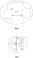
- a manipulator system 10 which comprises laser scanners 2 in order to monitor a protective field 3.
- the protective field 3 has a complex contour.
- a projection device comprising a projector 4 is provided on the manipulator system 10.
- the projector 4 throws a light projection 5 onto the floor.
- protective field information is signaled to the environment.
- This light projection 5 is larger than the protective field 3 and identifies an area on the floor which includes the protective field 3.
- the light projection is greatly simplified in order to be able to better communicate the protective field.
- the person skilled in the art understands that the shape of the light projection or the degree of simplification of the protective field to be communicated can be variably adapted.
- the protective field 3 can adapt its shape dynamically during the operation of the manipulator system 10. A worker thus recognizes that he should not enter the area marked by the light projection 5, as this could lead to a protective field violation.
- a locally stationary manipulator system 10 which comprises a manipulator 11 which is movable.
- a protective field 3 is locally monitored here by means of a monitoring device 2 in order to prevent collisions between the manipulator 11 and an object penetrating into the protective field 3.
- a projection device comprising a projector 4 is used to generate a light projection 5 which, as in FIG Figure 1 covers a larger area than the protective field 3 monitored by means of the monitoring device 2. In this way, a worker can be signaled which area he should not approach.
- the light projections 5 can only be formed by a line which can extend around the manipulator system 10, but does not have to form a closed contour.
- the light projection 5 can advantageously also be partially or completely illuminated by the projection device.
- manipulator system 10 can be stationary or movable.
- driverless transport systems are described, which are also applicable to stationary manipulator systems.
- the driverless transport systems can also be part of the manipulator system 10 of the Figure 1 or 2 be.
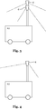
- a driverless transport system 12 which comprises two projectors 4.
- the projectors 4 are provided at an elevated position and can produce various light projections on the ground. By selectively driving one of the projectors 4 it can be controlled which of the corresponding two different light projections is to be projected.
- both projectors 4 can project simultaneously and jointly signal protective field information to the environment.
- a driverless transport system 12 is shown, with a projector 4 provided at an elevated level.
- This projector 4 can project various patterns. The light or the pattern is projected directly onto the floor.
- the projector4 can variably adapt its projection pattern.
- the transport system 12 can therefore be used very flexibly, since, depending on the application, an individual projection pattern can be generated in order to signal the respective protective field information to the environment.
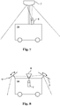
- a driverless transport system 12 is shown, with three projectors 4 which are movably arranged. Since the projectors 4 are movably mounted, the Position of the light projection can be changed.
- the projectors 4 can be rotatably and / or pivotably mounted. By changing the angle of the projectors 4 relative to the driverless transport system 10, the position of the light projection on the floor can be varied, and thus the projection can be changed. Furthermore, by moving one or more projectors 4, a specific pattern can be displayed on the floor.
- a driverless transport system 12 in which a projector 4 is provided on a rotatable plate 6.
- a projector can be provided on the system in a rotatable manner.
- the projector 4 generates a visible point projection onto the floor.
- the projector 4 can be permanently mounted so that a circle is displayed on the floor by rotating the projector 4.
- a plurality of such projectors can also be provided on the plate 6. By switching between these projectors, different diameters can advantageously be displayed on the floor.
- the projector 4 can also be mounted pivotably so that a desired pattern can be displayed by a mechanical guide. By changing the position of the guide, the size of the pattern can be changed.
- the angle of the projector 4 can be actuated, for example electrically, pneumatically or hydraulically. By means of a corresponding control signal, the angle of the projector 4 can be adjusted as a function of the angle of the rotatable plate 6, so that a desired projection pattern is projected onto the floor.
- a driverless transport system 12 on which a lens 7 is mounted in an elevated position.
- a mirror and / or a prism can also be used.
- a projector 4 provided on the transport system 12 is aimed at this lens 7.
- the lens reflects or refracts the light emitted by the projector 4 in such a way that a desired light projection is displayed on the floor.
- the lens 7 can be moved in order to change the position of the light projection.
- the breaking property of the lens can also be varied in order to project a desired pattern at a desired location in the surroundings.
- the projection generated can also be varied by varying the radiation emitted by the projector 4.
- several projectors 4 can also be directed at the lens 7 in order to generate a desired projection pattern.
- a driverless transport system 12 in which the light emitted by a projector 4 is reflected by a plurality of mirrors 8, 9 in order to display the desired light projection on the floor.
- the outer mirrors 9 can be movable in order to control the light projection.
- a driverless transport system 12 which moves to the right in the figure.
- projectors which here include laser sources, are controlled in such a way that different patterns are displayed in front of and to the side of the driverless transport system 12. By displaying lines, it can be signaled directly that these areas should not be entered.
- the light projection 5 on the floor here also includes symbols which make it clear to a worker that the area marked by the light projection 5 should not be entered.
- the acoustic signals can also be output if an optical signaling of information is not possible, or if a source of error is not possible was remedied within a predefined time interval after optical signaling.
- Additional information can also be displayed through the projection.
- the color of the projections can be changed if the protective field is violated.
- textual and / or symbolic information can also be displayed, or an upcoming change in the protective field can be displayed in order to inform an HRC environment accordingly.
- the areas to be avoided by people can be clearly identified. Hatching and standardized warning symbols can be mapped directly to the decisive position using powerful light emitters such as lasers.
- a meaningful current flow of the laser source can preferably be monitored in order to detect a defect.
Landscapes
- Engineering & Computer Science (AREA)
- Mechanical Engineering (AREA)
- General Engineering & Computer Science (AREA)
- Robotics (AREA)
- Manufacturing & Machinery (AREA)
- Quality & Reliability (AREA)
- Physics & Mathematics (AREA)
- General Physics & Mathematics (AREA)
- Automation & Control Theory (AREA)
- Manipulator (AREA)
- Control Of Position, Course, Altitude, Or Attitude Of Moving Bodies (AREA)
Description
- Die vorliegende Erfindung betrifft ein Manipulatorsystem, insbesondere ein fahrerloses Transportsystem, als auch ein Verfahren zum Betreiben eines Manipulatorsystems.
- Roboter, und insbesondere Industrieroboter, sind frei-programmierbare, programmgesteuerte Handhabungsgeräte, welche beispielsweise in der Montage oder Fertigung eingesetzt werden können. Dabei können sie entsprechend einer vorgegebenen Bahnplanung definierte Bewegungen durchführen und Werkstücke handhaben oder bearbeiten. Die eigentliche Mechanik eines Roboters kann als Manipulator bezeichnet werden. Diese besteht in der Regel aus einer Anzahl an beweglichen, aneinander geketteten Gliedern oder Achsen.
- Fahrerlose Transportsysteme (FTS) werden häufig in Produktionsbetrieben eingesetzt, um beispielsweise Bauteile oder Werkstücke von einer Arbeitsstation zu einer nächsten Arbeitsstation zu transportieren. Ein fahrerloses Transportsystem kann dabei seinen eigenen Fahrantrieb aufweisen, und automatisch gesteuert werden. Fahrerlose Transportsysteme können auch eingesetzt werden, um Manipulatoren oder Industrieroboter zu bewegen, sodass diese an verschiedenen Arbeitsstationen bestimmte Arbeitsschritte durchführen können.
- Generell kann ein fahrerloses Transportsystem als Fördersystem betrachtet werden, welches zumindest ein fahrerloses Transportfahrzeug umfassen kann. Das Fahrzeug kann dabei multi-direktional und insbesondere omni-direktional beweglich sein. Zu diesem Zweck kann es entsprechende omni-direktionale Räder aufweisen, um eine hohe Beweglichkeit und Flexibilität des fahrerlosen Transportsystems zu ermöglichen. Fahrerlose Transportfahrzeuge werden automatisch gesteuert. Hierzu kann beispielsweise eine fahrzeuginterne Steuereinrichtung verwendet werden, welche entsprechende Antriebe des fahrerlosen Transportsystems ansteuert, um eine gewünschte Bewegung des Fahrzeugs zu bewirken. Der Steuereinrichtung kann ein Programm zugrunde liegen, welches die Bewegung des Fahrzeugs, gekennzeichnet durch die Richtung und Geschwindigkeit, vorgibt.
- Um einen sicheren Betrieb eines Manipulators oder eines fahrerlosen Transportsystems in einer Werkhalle zu ermöglichen, sind diese häufig mit Laserscannern ausgerüstet, mit welchen ein sogenanntes Schutzfeld (häufig auch Sicherheitsfläche oder Sicherheitsbereich genannt) überwacht werden kann. Insbesondere kann das Schutzfeld einen horizontalen Bereich um den Manipulator herum abdecken. Wenn beispielsweise ein Hindernis, wie beispielsweise ein Mensch, in das Schutzfeld eintritt, kann mittels der Laserscanner eine Verletzung des Schutzfeldes erkannt bzw. detektiert werden. In Reaktion hierauf kann der Manipulator z.B. stoppen, um eine mögliche Kollision zu vermeiden. Somit wird eine sichere Mensch-Roboter-Kollaboration (MRK) ermöglicht. Insbesondere ist eine solche Schutzfeldüberwachung bei dem Einsatz von fahrerlosen Transportsystemen notwendig, da diese oft ortsflexibel in einer MRK-Umgebung eingesetzt werden.
- Die Schutzfelder können an die jeweilige Umgebung oder den Betrieb des Manipulators oder des fahrerlosen Transportsystems angepasst sein. Wenn ein Manipulator beispielsweise ein großes Werkzeug führt, kann ein großes Schutzfeld verwendet werden, um einen entsprechend größeren Arbeitsbereich abdecken zu können. In einem anderen Beispiel kann bei einem fahrerlosen Transportsystem das Schutzfeld entsprechend der Geschwindigkeit des fahrerlosen Transportsystems angepasst werden. Beispielsweise kann bei einer hohen Geschwindigkeit ein größeres Schutzfeld verwendet werden, um Verzögerungen und längere Bremswege zu berücksichtigen.
- In der Patentschrift
EP 2 558 886 B1 wird eine Einrichtung zur Überwachung eines dreidimensionalen Sicherheitsbereichs beschrieben. Diese Überwachungseinrichtung umfasst eine Aufnahmevorrichtung, wie beispielsweise eine Infrarotkamera, und einen Projektor, welcher beispielsweise im infraroten Bereich einen zu überwachenden Sicherheitsbereich erzeugt. Mittels der Infrarotkamera werden Abbilder des Sicherheitsbereichs aufgenommen, und mittels einer Auswertevorrichtung dahingehend ausgewertet, ob Personen oder Objekte in den Sicherheitsbereich eingedrungen sind. Nachteilig ist daran, dass die Projektionsvorrichtung Teil der Überwachungseinrichtung ist und daher nicht unabhängig von dieser betrieben werden kann. Fällt die Projektionsvorrichtung bspw. aus, so ist ein sicherer Betrieb des Systems nicht mehr gewährleistet. Ferner kann die Projektionsvorrichtung nur eingesetzt werden, wenn eine für eine sichere Überwachung notwendige Lichtstärke erreicht werden kann, was insbesondere bei hoher Umgebungslichtstäke problematisch werden kann. - Bei einem fahrerlosen Transportsystem kann das Schutzfeld beispielsweise nur in Fahrtrichtung des Fahrzeugs ausgerichtet sein, um ungewollte Schutzfeldverletzungen zu unterbinden. Damit sich niemand seitlich zu nah an das Fahrzeug annähert, können Hinweisschilder an diesem Fahrzeug angebracht sein. Eine solche Anzeige ist jedoch unflexibel, und kann je nach Bauform des Fahrzeugs eventuell nicht an diesem angebracht werden. Solche Beschriftungen können nicht oder nur mit hohem Aufwand an eine momentane Fahrsituation angepasst werden.
- Das Dokument
DE 10 2010 007 027 A1 betrifft ein Verfahren zur Überwachung eines Manipulatorraumes eines mobilen Manipulators, insbesondere eines mobilen Roboters, durch Überwachen des Raumes auf nicht vorgesehene Objekte mittels einer Umgebungserfassungseinrichtung. - Der vorliegenden Erfindung liegt die Aufgabe zugrunde, ein Manipulatorsystem bereitzustellen, welches sicher in einer MRK-Umgebung betrieben werden kann.
- Diese und weitere Aufgaben, die aus der folgenden Beschreibung ersichtlich werden, werden durch ein Manipulatorsystem gemäß Anspruch 1 und ein Verfahren zum Betreiben eines Manipulatorsystems gemäß Anspruch 13 gelöst.
- Die vorliegende Erfindung betrifft ein Manipulatorsystem, insbesondere ein fahrerloses Transportsystem. Das Manipulatorsystem kann dabei einen Manipulator umfassen, welcher auch eine mobile Basis aufweisen kann. Vorzugsweise umfasst das Manipulatorsystem ein fahrerloses Transportfahrzeug, welches vorzugsweise einen Manipulator tragen und bewegen kann. Vorzugsweise eignet sich das Manipulatorsystem für den Einsatz in einer MRK-Umgebung. Das fahrerlose Transportsystem kann dabei einen mobilen Manipulator umfassen, und beispielsweise einen Roboterarm aufweisen.
- Das Manipulatorsystem weist eine Überwachungseinrichtung auf, die eingerichtet ist, um ein Schutzfeld des Manipulatorsystems zu überwachen. Durch Überwachen des Schutzfeldes kann beispielsweise erkannt werden, dass sich ein Objekt oder Hindernis in dem Schutzfeld befindet, und folgend eine entsprechende Reaktion des Manipulatorsystems eingeleitet werden. Das Schutzfeld kann dabei dynamisch an die Umgebung oder einen Zustand des Manipulatorsystems angepasst sein, und dabei beispielsweise eine komplexe Kontur aufweisen, um einen möglichst sicheren Betrieb des Manipulatorsystems zu ermöglichen.
- Vorzugsweise umfasst die Überwachungseinrichtung ein Mittel zur Erfassung von Objekten in dem Schutzfeld, wobei das Mittel vorzugsweise eine laser-, kamera-, radar- , ultraschall-, infrarot- und/oder lidargestützte Vorrichtungen umfasst. Die Überwachungseinrichtung kann vorzugsweise ein Mittel umfassen, welches beispielsweise die Schutzfeldüberwachung unter Verwendung von Infrarot-, Ultraschall-, parallaktischer oder schärfe- bzw. kontrastoptischer Entfernungsmessung ermöglicht. Die Überwachungseinrichtung kann hierzu optische, opto-elektronische, und/oder bildverarbeitende Systeme verwenden. Vorzugsweise kann die Überwachungseinrichtung ein Multi-Kamerasystem, eine Stereo-Kamera, eine 3D-Kamera und/oder eine Flugzeitkamera umfassen, um die Schutzfeldüberwachung zu ermöglichen. Besonders bevorzugt umfasst die Überwachungseinrichtung einen oder mehrere Laserscanner zur Erfassung von Objekten in dem Schutzfeld. Solche Laserscanner arbeiten zuverlässig und erlauben es, hohe Sicherheitsanforderungen einzuhalten. Generell kann das erfassbare Objekt jeder Körper sein, welcher in einer Umgebung des Manipulatorsystems einen gewissen Raum einnimmt und mittels der Überwachungseinrichtung erfassbar ist oder mittels dieser detektiert werden kann. Die Überwachungseinrichtung muss das Objekt in dem Schutzfeld dabei nicht unbedingt identifizieren, es ist vielmehr für einen sicheren Einsatz des Manipulatorsystems ausreichend, dass das bloße Vorhandensein des Objekts in dem Schutzbereich erkannt wird.
- Das Manipulatorsystem umfasst zusätzlich zur Überwachungseinrichtung, d.h. vorzugsweise auch strukturell unabhängig von der Überwachungseinrichtung, eine Projektionsvorrichtung, die eingerichtet ist, um Schutzfeldinformation an die Umgebung des Manipulatorsystems zu projizieren. Die Projektionsvorrichtung ist nicht mit der Überwachungseinrichtung identisch. Vorzugsweise handelt es sich bei der Projektionsvorrichtung und der Überwachungseinrichtung um zwei getrennte Systeme, welche jedoch mittels derselben Steuerung angesteuert werden können und die funktional miteinander zusammenwirken und dementsprechend funktional vorzugsweise auch gekoppelt sind. Die Projektionsvorrichtung und die Überwachungseinrichtung können getrennte Steuerungen aufweisen, welche funktional miteinander gekoppelt sein können bzw. Daten austauschen können. Die Projektionsvorrichtung und Überwachungseinrichtung können als getrennte Systeme zwar in einem gemeinsamen Gehäuse untergebracht sein, um bspw. den benötigten Bauraum zu verringern. Vorzugsweise sind sie jedoch räumlich getrennt angeordnet, wobei die Projektionsvorrichtung an einer Stelle vorgesehen ist, die ein optimales projizieren ermöglicht (z.B. von einer erhöhten Position), und die Überwachungseinrichtung an einer anderen Stelle, von der die Überwachung optimal möglich ist (z.B. an einer seitlichen Position an einem Fahrzeug).
- Die Schutzfeldinformation kann dabei Information sein, die im Zusammenhang zu dem Schutzfeld steht. Beispielsweise kann eine Geschwindigkeitsänderung eine Änderung eines Schutzfeldes bzw. eine Schutzfeldanpassung hervorrufen, welche wiederum durch die Schutzfeldinformation beschrieben werden kann. Die Projektionsvorrichtung kann beispielsweise einen Projektor umfassen, welcher Licht emittieren kann, um die Schutzfeldinformation an die Umgebung zu projizieren. Durch dieses Projizieren kann die Schutzfeldinformation insbesondere an die MRK-Umgebung des Manipulatorsystems signalisiert werden. Vorzugsweise kann dabei jegliche Information, die in einer Steuerung des Manipulatorsystems bereitgestellt ist, einer Person bzw. einem Werker in der Umgebung jedoch unbekannt sein kann, durch das Projizieren signalisiert werden. Dies gilt insbesondere für Informationen, welche sicherheitsrelevante Aspekte, wie beispielsweise Ausmaße von Schutzfeldern oder Zustandsänderungen des Manipulatorsystems umfassen.
- Es ist somit vorteilhaft möglich, sicherheitsrelevante Informationen an die Umgebung des Manipulatorsystems zu signalisieren. Beispielsweise kann auf dem Boden um das Manipulatorsystem herum mittels der Projektionsvorrichtung im Wesentlichen der Bereich optisch gekennzeichnet werden, welcher durch die Überwachungseinrichtung überwacht wird. Dadurch kann ein Werker direkt erkennen, wie nahe er sich dem Manipulatorsystem annähern kann, ohne das Schutzfeld zu verletzen. Hierzu muss nicht eine komplexe Kontur des Schutzfeldes durch die Projektionsvorrichtung optisch gekennzeichnet werden. Vielmehr kann eine vereinfachte Kontur projiziert werden, welche im Wesentlichen das Schutzfeld abdeckt. Hierdurch wird der Projektionsaufwand deutlich verringert. Ferner kann mit der Projektionsvorrichtung beispielsweise dargestellt werden, in welchem Bereich ein fahrerloses Transportsystem fahren wird, sodass ein Werker diesen Bereich verlassen kann. Mittels der Projektionsvorrichtung können auch Komplikationen bzw. Probleme signalisiert werden. Beispielsweise kann somit signalisiert werden, dass ein Weg versperrt ist, sodass ein Werker die Störung beheben kann. Oft sind Fehlerquellen nicht direkt ersichtlich, durch die Projektionsvorrichtung kann jedoch einem Werker intuitiv mitgeteilt werden, welche Fehlerquelle vorliegt und wie diese behoben werden kann. Beispielsweise kann optisch dargestellt werden, dass die momentanen Schutzfeldausmaße größer als ein zu durchfahrender Korridor ist.
- Die Schutzfeldüberwachung kann somit beispielsweise mittels Ultraschall- oder Infrarottechnik durchgeführt werden, wobei diese Überwachung für Menschen bzw. Werker nicht erkennbar ist. Die Projektionsvorrichtung erlaubt es dabei dem Werker in der Umgebung des Manipulatorsystems sichtbar zu signalisieren, welcher Bereich durch die Überwachungseinrichtung überwacht wird. Der Werker weiß nun zumindest grob, wo sich das für ihn unsichtbare Schutzfeld befindet. Dadurch kann effizient verhindert werden, dass der Werker ungewollt das Schutzfeld verletzt.
- Vorzugsweise ist die Überwachungseinrichtung eingerichtet, um das Schutzfeld des Manipulatorsystems zu überwachen, wenn die Projektionsvorrichtung keine Schutzfeldinformation projiziert. Die Überwachungseinrichtung und die Projektionsvorrichtung können somit zwei Komponenten des Manipulatorsystems darstellen, welche im Wesentlichen unabhängig voneinander angesteuert werden können. Obwohl beide unter Berücksichtigung eines zu überwachenden Schutzfeldes angesteuert werden können, geschieht diese Ansteuerung vorteilhaft unabhängig voneinander. Die Überwachungseinrichtung kann dabei separat zu der Projektionsvorrichtung an dem Manipulatorsystem bereitgestellt sein. Selbst wenn die Projektionsvorrichtung von dem Manipulatorsystem entfernt wird, kann die Überwachungseinrichtung uneingeschränkt das Schutzfeld des Manipulatorsystems weiter überwachen. Somit kann sichergestellt werden, dass ein Defekt der Projektionsvorrichtung keine Auswirkung auf die Überwachungseinrichtung hat, sodass sicherheitsrelevante Aspekte unberührt bleiben. Ebenso kann beispielsweise die Projektionsvorrichtung uneingeschränkt Schutzfeldinformationen an die Umgebung des Manipulatorsystems projizieren, selbst wenn die Überwachungseinrichtung selber ausgeschaltet ist. Dies ist vorteilhaft, da in einem derartigen Fall die Projektionsvorrichtung ein zukünftiges Schutzfeld anzeigen kann, bevor dieses tatsächlich aktiviert wird. Bei einer vorgesehenen Vergrößerung des Schutzfeldes kann somit einem Werker bspw. signalisiert werden, dass er einen bestimmten Bereich verlassen muss, bevor tatsächlich das größere Schutzfeld aktiviert wird. Hiermit können ungewollte Stopps des Systems vermieden werden.
- Die Projektionsvorrichtung ist eingerichtet, um eine Lichtprojektion an die Umgebung des Manipulatorsystems zu erzeugen, um die Schutzfeldinformation sichtbar zu projizieren. Die Lichtprojektion kann somit eine gezielte Projektion auf die Umgebung darstellen, und kann dabei eindeutig durch einen Werker auf der Umgebung erkannt werden. Mit der Projektionsvorrichtung wird somit Licht emittiert, dessen Wellenlänge im sichtbaren Bereich liegt. Somit kann die Schutzfeldinformation optisch einem Menschen mitgeteilt werden. Vorzugsweise ist die Lichtprojektion zumindest teilweise auf den Boden der Umgebung gerichtet. Die Lichtprojektion muss dabei nicht den Boden treffen, sondern kann beispielsweise ein Objekt treffen, welches auf dem Boden der Umgebung vorhanden ist. Ein Werker erkennt auch in diesem Fall direkt die Schutzfeldinformation, beispielsweise erkennt er, wie nahe er sich dem Manipulatorsystem annähern darf. Ferner kann durch Variation der Wellenlänge zusätzliche Information an die Umgebung signalisiert werden: Beispielsweise kann eine rote Farbe anzeigen, dass eine Schutzfeldüberwachung aktiv ist, während eine blaue Farbe anzeigen kann, dass das Manipulatorsystem in einem interaktivem Modus arbeitet. Eine rote Farbe kann auch kennzeichnen, dass eine Betriebstemperatur des Manipulatorsystems über einen Grenzwert liegt, sodass sich ein Bediener von dem Manipulatorsystem entfernen sollte. Das Projizieren von Schutzfeldinformation mittels der Projektionsvorrichtung kann vorzugsweise unter Berücksichtigung von bekannten bzw. bereitgestellten Umgebungsinformationen, wie beispielsweise 3D-Umgebungsinformation erfolgen. Beispielsweise können bekannte Höheninformationen berücksichtigt werden, um die Schutzfeldinformation präzise auch bei unterschiedlichen Höhen der Umgebung zu projizieren.
- Vorzugsweise ist eine Kontur der Lichtprojektion rund, oval, kreisförmig oder elliptisch. Die Kontur kann dabei vorzugsweise frei konfigurierbar bzw. frei wählbar sein. Dadurch kann ohne großen Aufwand grob der Bereich um das Manipulatorsystem gekennzeichnet werden, welcher von einem Mensch nicht betreten werden soll. Somit können auch komplexe Konturen des Schutzfeldes vereinfacht an die Umgebung signalisiert werden. Die Kontur der Lichtprojektion kann auch rechteckig sein, und beispielsweise einen seitlichen Bereich eines fahrerlosen Transportsystems kennzeichnen, welcher von einem Menschen gemieden werden sollte. Vorzugsweise ist die Kontur der Lichtprojektion verschieden von einer Kontur des Schutzfeldes. Die Lichtprojektion kann somit sehr flexibel eingesetzt werden, um Informationen an die MRK-Umgebung zu signalisieren. Dies ist ein weiterer Vorteil einer strukturellen Trennung von Überwachungseinrichtung und Projektionseinrichtung.
- Vorzugsweise umfasst die Lichtprojektion eine Kodierung und insbesondere ein Muster und/oder ein Symbol entsprechend der Schutzfeldinformation. Beispielsweise kann somit mittels eines Pfeils angedeutet werden, in welche Richtung ein fahrerloses Transportsystem fährt, bzw. welcher Bereich zukünftig von der Überwachungseinrichtung überwacht wird. Ferner kann ein genormtes Warnsymbol an die Umgebung projiziert werden, welches beispielsweise für Werker unmissverständlich einen Gefahrbereich kennzeichnen kann.
- Vorzugsweise entspricht eine horizontale Erstreckung der Lichtprojektion zumindest einer horizontalen Erstreckung des Schutzfeldes. Es wird also beispielsweise auf dem Boden ein Bereich gekennzeichnet, welcher mindestens so groß ist, wie der mittels der Überwachungseinrichtung überwachte Bereich des Bodens. Somit kann ein Werker direkt erkennen, welcher Bereich überwacht wird bzw. wo er sich nicht aufhalten sollte.
- Vorzugsweise deckt die Lichtprojektion auf einer horizontalen Ebene zumindest einen durch das Schutzfeld abgedeckten Bereich ab. Insbesondere vorzugsweise deckt die Lichtprojektion auf der horizontalen Ebene einen größeren Bereich ab, als den durch das Schutzfeld abgedeckten Bereich. Die horizontale Ebene kann beispielsweise der Boden der Umgebung sein, oder eine andere zweidimensionale Schnittfläche durch den dreidimensionalen Raum. Vorzugsweise entspricht der größere Bereich, welcher durch die Lichtprojektion abgedeckt wird, 101% bis 150%, weiter vorzugsweise 102% bis 140%, weiter vorzugsweise 103% bis 130%, weiter vorzugsweise 104% bis 120% und am meisten bevorzugt 105% bis 110% des durch das Schutzfeld abgedeckten Bereichs. Der Fachmann versteht, dass diese Bereichsangaben kombinierbar sind, entsprechend der jeweiligen Anwendungsform. Somit kann tendenziell ein größerer Bereich optisch gekennzeichnet werden, als durch die Überwachungseinrichtung überwacht wird. Das Schutzfeld kann beispielsweise dynamisch seine Größe ändern. Da ein Werker einen größeren Bereich meidet, wird hierdurch keine ungewollte Schutzfeldverletzung hervorgerufen.
- Ein momentanes Schutzfeld kann einer momentanen Überwachung des Manipulatorsystems zugrunde liegen. In einem momentanen Betrieb kann somit die Überwachungseinrichtung das momentane Schutzfeld, bzw. aktuell gültige Schutzfeld des Überwachungssystems überwachen. Erfindungsgemäß ist das Schutzfeld ein zukünftiges Schutzfeld, welches einer zukünftigen Überwachung des Manipulatorsystems zu einem späteren Zeitpunkt zugrunde liegt. Es kann somit durch die Lichtprojektion ein Bereich auf dem Boden abgedeckt werden, welcher zu einem späteren Zeitpunkt durch die Überwachungseinrichtung überwacht wird. Dadurch kann einem Werker signalisiert werden, dass sich die Schutzfeldgröße ändern wird, sodass der Werker den betroffenen Bereich verlassen kann.
- Vorzugsweise umfasst die Projektionsvorrichtung zumindest einen Projektor und ein separat von dem Projektor bereitgestelltes Umlenkmittel. Ein Projektor kann dabei eine Lichtquelle umfassen, um eine Projektion hervorzurufen. Das Umlenkmittel lenkt dabei das von dem Projektor emittierte Licht auf die Umgebung. Somit kann präzise definiert werden, wie die Projektion und insbesondere Lichtprojektion an die Umgebung erfolgen soll. Ferner kann somit auch bei größeren Manipulatorsystemen die Schutzfeldinformation effizient an die Umgebung projiziert werden. Insbesondere vorzugsweise umfasst das Umlenkmittel einen Spiegel und/oder eine Linse, und das Umlenkmittel kann ferner vorzugsweise beweglich angeordnet sein. Somit kann durch Bewegen des Spiegels, zum Beispiel, ein bestimmtes Muster auf dem Boden erzeugt werden.
- Vorzugsweise umfasst die Projektionsvorrichtung zumindest einen Projektor, welcher beweglich und vorzugsweise drehbar an dem Manipulatorsystem bereitgestellt ist. Durch Bewegen und/oder Drehen des Projektors kann somit ein bestimmtes Muster beispielsweise auf den Boden projiziert werden. Insbesondere vorzugsweise kann der Projektor auf einer drehbaren Plattform bereitgestellt sein, welche sich schnell dreht, sodass ein durch den Projektor auf den Boden projizierter Punkt durch einen Menschen als geschlossene Kontur bzw. Linie auf dem Boden dargestellt wird.
- Vorzugsweise umfasst die Projektionsvorrichtung zumindest einen Projektor und zumindest eine Maske. Die Maske wird dabei von dem Projektor beleuchtet und definiert ein Projektionsmuster. Durch diese Maske kann ein bestimmter Lichtkegel bzw. eine gewünschte Lichtprojektion hervorgerufen werden, welche auf den Boden projiziert werden kann. Vorzugsweise können mehrere Masken bereitgestellt sein, welche während des Betriebs selektiv verwendet werden können. Vorzugsweise können eine oder mehrere Masken veränderlich sein, um die Projektion zu ändern.
- Weiterhin betrifft die Erfindung ein Verfahren zum Betreiben eines Manipulatorsystems. Insbesondere eignet sich das Verfahren dabei zum Betreiben eines der oben beschriebenen Manipulatorsysteme. Das Manipulatorsystem umfasst dabei eine Überwachungseinrichtung, und ferner bzw. zusätzlich eine Projektionsvorrichtung. Das Verfahren umfasst ein Überwachen eines Schutzfeldes des Manipulatorsystems mittels der Überwachungseinrichtung. Ferner umfasst das Verfahren ein Projizieren von Schutzfeldinformationen an die Umgebung des Manipulatorsystems mittels der Projektionsvorrichtung. Die einzelnen Schritte des Verfahrens können dabei mittels einer Steuerung durchgeführt werden, welche eine oder mehrere Steuereinrichtungen umfassen kann. Beispielsweise kann die Überwachungseinrichtung und Projektionsvorrichtung durch zwei getrennte Steuereinrichtungen geregelt werden, die in Kommunikation miteinander stehen können.
- Das oben beschriebene Projizieren von Schutzfeldinformationen erfolgt dabei vorzugsweise auf einer der folgenden Größen: eine Form und/oder eine Formänderung des Schutzfeldes, eine Größe und/oder eine Größenänderung des Schutzfeldes, einen Zustand (bzw. momentaner Zustand) und/oder eine Zustandsänderung des Manipulatorsystems, eine Geschwindigkeit und/oder eine Beschleunigung des Manipulatorsystems, eine Orientierung und/oder eine Umorientierung des Manipulatorsystems, eine Bahnplanung des Manipulatorsystems, einen Betriebsmodus des Manipulatorsystems, eine Umgebungskarte. Somit kann jegliche Information, welche eine Konfiguration des Schutzfeldes oder einen Aspekt der Schutzfeldüberwachung betrifft, an die Umgebung projiziert werden, bzw. einem Werker optisch signalisiert werde. Insbesondere die Bahnplanung, welche die Bewegung des Manipulatorsystems vorgeben kann, kann somit herangezogen werden, um sicherheitsrelevante Informationen an die Umgebung zu signalisieren.
- Vorzugsweise erfolgt das Projizieren von Schutzfeldinformation quasikontinuierlich während des Betriebs des Manipulatorsystems. Vorzugsweise kann das Projizieren in jedem Interpolationstakt bzw. IPO-Takt des Manipulatorsystems angepasst werden. Somit kann flexibel und dynamisch die Schutzfeldinformation an die Umgebung signalisiert werden.
- Im Folgenden wird die vorliegende Erfindung unter Bezugnahme auf die beiliegenden Figuren beschrieben. Dabei sind gleiche Merkmale mit gleichen Bezugszeichen gekennzeichnet. Es zeigt:
-
Fig. 1 schematisch ein Manipulatorsystem gemäß einer Ausführungsform; -
Fig. 2 schematisch ein Manipulatorsystem umfassend einen stationären Manipulator gemäß einer weiteren Ausführungsform; -
Fig. 3 schematisch ein fahrerloses Transportsystem mit zwei Projektoren gemäß einer weiteren Ausführungsform; -
Fig. 4 schematisch ein fahrerloses Transportsystem mit einem Projektor gemäß einer weiteren Ausführungsform; -
Fig. 5 schematisch ein fahrerloses Transportsystem mit beweglichen Projektoren gemäß einer weiteren Ausführungsform; -
Fig. 6 schematisch ein fahrerloses Transportsystem mit einem drehbaren Projektor gemäß einer weiteren Ausführungsform; -
Fig. 7 schematisch ein fahrerloses Transportsystem mit einem Projektor und einer Linse gemäß einer weiteren Ausführungsform; -
Fig. 8 schematisch ein fahrerloses Transportsystem mit einem Projektor und Spiegeln gemäß einer weiteren Ausführungsform; und -
Fig. 9 schematisch ein fahrerloses Transportsystem mit mehreren Lichtprojektionen gemäß einer weiteren Ausführungsform. - In der
Figur 1 ist ein Manipulatorsystem 10 dargestellt, welches Laserscanner 2 umfasst, um ein Schutzfeld 3 zu überwachen. Das Schutzfeld 3 weist dabei eine komplexe Kontur auf. Ferner ist eine Projektionsvorrichtung umfassend einen Projektor 4 an dem Manipulatorsystem 10 bereitgestellt. Der Projektor 4 wirft eine Lichtprojektion 5 auf den Boden. Hierdurch wir eine Schutzfeldinformation an die Umgebung signalisiert. Diese Lichtprojektion 5 ist dabei größer als das Schutzfeld 3, und kennzeichnet auf dem Boden einen Bereich, welcher das Schutzfeld 3 umfasst. Die Lichtprojektion ist in diesem Fall stark vereinfacht um das Schutzfeld besser kommunizieren zu können. Der Fachmann versteht, dass die Form der Lichtprojektion bzw. der Grad der Vereinfachung des zu kommunizierenden Schutzfeldes variabel anpassbar ist. Das Schutzfeld 3 kann seine Form dabei dynamisch während des Betriebs des Manipulatorsystems 10 anpassen. Somit erkennt ein Werker, dass er nicht den durch die Lichtprojektion 5 gekennzeichneten Bereich betreten sollte, da dies zu einer Schutzfeldverletzung führen könnte. - In der
Figur 2 ist ein örtlich stationäres Manipulatorsystem 10 dargestellt, welches einen Manipulator 11 umfasst, der beweglich ist. Wie bei derFigur 1 wird hier mittels einer Überwachungseinrichtung 2 ein Schutzfeld 3 lokal überwacht, um Kollisionen zwischen dem Manipulator 11 und einem in das Schutzfeld 3 eindringenden Objekt zu verhindern. Ferner wird mit einer Projektionsvorrichtung umfassend einen Projektor 4 eine Lichtprojektion 5 erzeugt, welche wie in derFigur 1 einen größeren Bereich abdeckt, als das mittels der Überwachungseinrichtung 2 überwachte Schutzfeld 3. Somit kann einem Werker signalisiert werden, welchem Bereich er sich nicht nähern sollte. - Die Lichtprojektionen 5 können dabei lediglich durch eine Linie gebildet sein, welche sich um das Manipulatorsystem 10 herum erstrecken kann, jedoch nicht eine geschlossene Kontur bilden muss. Die Lichtprojektion 5 kann vorteilhaft auch teilweise oder vollständig füllend durch die Projektionsvorrichtung beleuchtet werden.
- Das in den
Figuren 1 und 2 dargestellte Manipulatorsystem 10 kann stationär oder beweglich sein. In denFiguren 3 bis 8 werden Ausführungsformen von fahrerlosen Transportsystem beschrieben, welche ebenso bei stationären Manipulatorsystemen anwendbar sind. Die fahrerlosen Transportsysteme können dabei auch Teil des Manipulatorsystems 10 derFigur 1 oder 2 sein. - In der
Figur 3 ist ein fahrerloses Transportsystem 12 dargestellt, welches zwei Projektoren 4 umfasst. Die Projektoren 4 sind an einer erhöhten Position bereitgestellt und können verschiedene Lichtprojektionen auf den Boden erzeugen. Durch wahlweises Ansteuern einer der Projektoren 4 kann gesteuert werden, welches der entsprechenden beiden verschiedenen Lichtprojektionen projiziert werden soll. Somit kann, wenn beispielsweise nur zwei verschiedene Schutzfeldkonfigurationen des fahrerlosen Transportsystems vorliegen, diese kostengünstig mittels zwei verschiedenen, aber technisch einfachen Projektoren 4 signalisiert werden. Ferner können auch beide Projektoren 4 gleichzeitig Projizieren, und gemeinsam Schutzfeldinformationen an die Umgebung signalisieren. - In der
Figur 4 ist ein fahrerloses Transportsystem 12 dargestellt, mit einem erhöht bereitgestellten Projektor 4. Dieser Projektor 4 kann verschiedene Muster projizieren. Dabei wird das Licht bzw. das Muster direkt auf den Boden projiziert. Der Projektor4 kann dabei sein Projektionsmuster variabel anpassen. Das Transportsystem 12 ist somit sehr flexibel einsetzbar, da je nach Anwendung ein individuelles Projektionsmuster erzeugt werden kann, um die jeweilige Schutzfeldinformation an die Umgebung zu signalisieren. - In der
Figur 5 ist ein fahrerloses Transportsystem 12 dargestellt, mit drei Projektoren 4, die beweglich angeordnet sind. Da die Projektoren 4 beweglich gelagert sind, kann die Position der Lichtprojektion verändert werden. Die Projektoren 4 können dabei drehbar und/oder schwenkbar gelagert sein. Durch eine Winkeländerung der Projektoren 4 relativ zum fahrerlosen Transportsystem 10 kann die Position der Lichtprojektion auf dem Boden variiert werden, und somit die Projektion verändert werden. Ferner kann durch die Bewegung eines oder mehrerer Projektoren 4 ein bestimmtes Muster auf dem Boden dargestellt werden. - In der
Figur 6 ist ein fahrerloses Transportsystem 12 dargestellt, bei welchem ein Projektor 4 auf einer drehbaren Platte 6 bereitgestellt ist. Der Fachmann versteht, dass ein Projektor dabei drehbar gelagert an dem System bereitgestellt sein kann. Von dem Projektor 4 wird eine sichtbare Punktprojektion auf den Boden erzeugt. Durch schnelles Drehen der drehbaren Platte 6 kann somit eine geschlossene Kontur auf dem Boden dargestellt werden. Der Projektor 4 kann dabei fest montiert sein, sodass durch Drehen des Projektors 4 ein Kreis auf dem Boden dargestellt wird. Obwohl nur ein Projektor 4 in dieser Ausführungsform dargestellt ist, können auch mehrere solcher Projektoren auf der Platte 6 bereitgestellt sein. Durch Umschalten zwischen diesen Projektoren können vorteilhaft verschiedene Durchmesser auf dem Boden dargestellt werden. Es können vorteilhaft auch mehrere Projektoren verwendet werden um eine geschlossene Kontur auf den Boden zu projizieren, wobei die Drehgeschwindigkeit durch die Verwendung mehrerer Projektoren verringert werden kann. Der Projektor 4 kann dabei auch schwenkbar gelagert werden, sodass durch eine mechanische Führung ein gewünschtes Muster dargestellt werden kann. Durch Veränderung der Position der Führung kann die Größe des Musters verändert werden. Ferner kann der Winkel des Projektors 4 aktuiert werden, beispielsweise elektrisch, pneumatisch oder hydraulisch. Durch ein entsprechendes Steuersignal kann der Winkel des Projektors 4 in Abhängigkeit vom Winkel der drehbaren Platte 6 eingestellt werden, sodass ein gewünschtes Projektionsmuster auf den Boden projiziert wird. - In der
Figur 7 ist ein fahrerloses Transportsystem 12 dargestellt, auf welchem eine Linse 7 in erhöhter Position montiert ist. Neben einer Linse kann auch ein Spiegel und/oder ein Prisma eingesetzt werden. Ein auf dem Transportsystem 12 bereitgestellter Projektor 4 ist auf diese Linse 7 gerichtet. Die Linse reflektiert bzw. bricht das von dem Projektor 4 emittierte Licht derart, dass eine gewünschte Lichtprojektion auf dem Boden dargestellt wird. Durch die Verwendung kann ein weiter Bereich um das fahrerlose Transportsystem 12 herum mittels des Projektors 4 erreicht bzw. beleuchtet werden. Die Linse 7 kann dabei bewegt werden, um die Position der Lichtprojektion zu verändern. Ferner kann auch die Brecheigenschaft der Linse variiert werden, um ein gewünschtes Muster an einer gewünschten Stelle an der Umgebung zu projizieren. Durch Variation der von dem Projektor 4 emittierten Strahlung kann ebenfalls die erzeugte Projektion variiert werden. Ferner können auch mehrere Projektoren 4 auf die Linse 7 gerichtet sein, um ein gewünschtes Projektionsmuster zu erzeugen. - In der
Figur 8 ist ein fahrerloses Transportsystem 12 dargestellt, bei welchem das von einem Projektor 4 emittierte Licht über mehrere Spiegel 8, 9 reflektiert wird, um die gewünschte Lichtprojektion auf dem Boden darzustellen. Hier können beispielsweise die äußeren Spiegel 9 beweglich sein, um die Lichtprojektion zu steuern. - Der Fachmann versteht, dass auch eine Kombination einzelner Aspekte der oben genannten Ausführungsformen möglich ist. Beispielsweise können mehrere Spiegel oder Linsen hintereinander angeordnet sein, die Reflektions- bzw. Brechungscharakteristik gezielt verändert werden, usw., um eine gewünschte Lichtprojektion darzustellen.
- In der
Figur 9 ist ein fahrerloses Transportsystem 12 dargestellt, welches sich in der Figur nach rechts bewegt. In Abhängigkeit der Fahrtrichtung und der Geschwindigkeit werden Projektoren, die hier Laserquellen umfassen, derart angesteuert, dass unterschiedliche Muster vor und seitlich des fahrerlosen Transportsystems 12 dargestellt werden. Durch Darstellen von Linien kann direkt signalisiert werden, dass diese Bereiche nicht betreten werden sollen. Die Lichtprojektion 5 auf dem Boden umfasst hier auch Symbole, welche einem Werker verdeutlichen, dass der durch die Lichtprojektion 5 markierte Bereich nicht betreten werden soll. - Vorzugsweise kann optisch und/oder akustisch signalisiert werden, wenn ein Schutzfeld seine Größe ändert. Dadurch kann ein Werker erkennen, dass ein gewünschter Bereich zu verlassen ist. Dabei kann insbesondere das Manipulatorsystem mit dem Umschalten der Schutzfelder warten bis der entsprechende Bereich frei ist. Die akustischen Signale können auch ausgegeben werden, wenn ein optisches Signalisieren von Informationen nicht möglich ist, oder wenn eine Fehlerquelle nicht innerhalb eines vordefinierten Zeitintervalls nach optischen Signalisieren behoben wurde.
- Durch die Projektion können auch weitere Informationen dargestellt werden. Beispielsweise kann die Farbe der Projektionen gewechselt werden, wenn das Schutzfeld verletzt wird. Zudem können auch textuelle und/oder symbolische Informationen eingeblendet werden, oder eine anstehende Schutzfeldänderung dargestellt werden, um eine MRK-Umgebung entsprechend zu informieren.
- Mit der Projektionsvorrichtung können die durch Menschen zu meidende Flächen eindeutig gekennzeichnet werden. Schraffuren und genormte Warnsymbole können durch starke Lichtstrahler, wie beispielsweise Laser, direkt auf die entscheidende Position abgebildet werden. Insbesondere vorzugsweise kann ein aussagekräftiger Stromfluss der Laserquelle überwacht werden, um einen Defekt zu erkennen.
-
- 10
- Manipulatorsystem
- 11
- Manipulator
- 12
- Fahrerloses Transportsystem
- 2
- Laserscanner
- 3
- Schutzfeld
- 4
- Projektor
- 5
- Lichtprojektion
- 6
- drehbare Platte
- 7
- Linse
- 8,9
- Spiegel
Claims (14)
- Fahrerloses Transportsystem (12), aufweisendeine Überwachungseinrichtung (2), die eingerichtet ist, um ein Schutzfeld (3) des Transportsystems (1, 12) zu überwachen, dadurch gekennzeichnet, dass das Transportsystem (1, 12) zusätzlich zur Überwachungseinrichtung, eine Projektionsvorrichtung (4) umfasst, die eingerichtet ist, um Schutzfeldinformation an die Umgebung des Transportsystems (1, 12) zu projizieren,wobei die Projektionsvorrichtung (4) eingerichtet ist, um eine Lichtprojektion (5) an die Umgebung des Transportsystems (1, 12) zu erzeugen, um die Schutzfeldinformation sichtbar zu projizieren,wobei die Schutzfeldinformation Information zu einem zukünftigen Schutzfeld umfasst, welches einer zukünftigen Überwachung des Transportsystems (1, 12) zu einem späteren Zeitpunkt zugrunde liegt.
- Transportsystem nach Anspruch 1, wobei die Überwachungseinrichtung (2) ein Mittel zur Erfassung von Objekten in dem Schutzfeld (3) umfasst, wobei das Mittel vorzugsweise eine laser-, kamera-, radar-, ultraschall-, infrarot- und/oder lidargestützte Vorrichtung umfasst.
- Transportsystem (1, 12) nach einem der Ansprüche 1 bis 2, wobei die Lichtprojektion (5) zumindest teilweise auf den Boden der Umgebung gerichtet ist.
- Transportsystem (1, 12) nach Anspruch 3, wobei eine Kontur der Lichtprojektion (5) rund, oval, kreisförmig, elliptisch oder rechteckig ist, und/oder wobei die Kontur der Lichtprojektion (5) verschieden von einer Kontur des Schutzfeldes (3) ist.
- Transportsystem (1, 12) nach Anspruch 3 oder 4, wobei die Lichtprojektion (5) eine Kodierung, und insbesondere ein Muster und/oder ein Symbol entsprechend der Schutzfeldinformation umfasst.
- Transportsystem (1, 12) nach einem der Ansprüche 3 bis 5, wobei eine horizontale Erstreckung der Lichtprojektion (5) zumindest einer horizontalen Erstreckung des Schutzfeldes (3) entspricht.
- Transportsystem (1, 12) nach einem der Ansprüche 3 bis 6, wobei die Lichtprojektion (5) auf einer horizontalen Ebene zumindest einen durch das Schutzfeld (3) abgedeckten Bereich abdeckt, und vorzugsweise auf der horizontalen Ebene einen größeren Bereich als den durch das Schutzfeld (3) abgedeckten Bereich abdeckt, wobei der größere Bereich vorzugsweise 101% bis 150%, weiter vorzugsweise 102% bis 140%, weiter vorzugsweise 103% bis 130%, weiter vorzugsweise 104% bis 120% und am meisten bevorzugt 105% bis 110% des durch das Schutzfeld (3) abgedeckten Bereichs entspricht.
- Transportsystem (1, 12) nach einem der Ansprüche 1 bis 7, wobei die Projektionsvorrichtung (4) zumindest einen Projektor (4) und ein separat von dem Projektor (4) bereitgestelltes Umlenkmittel (7, 8, 9) umfasst, welches das von dem Projektor (4) emittierte Licht auf die Umgebung lenkt, wobei das Umlenkmittel (7, 8, 9) vorzugsweise einen Spiegel (8, 9) und/oder eine Linse (7) umfasst, wobei das Umlenkmittel (7, 8, 9) ferner vorzugsweise beweglich angeordnet ist.
- Transportsystem (1, 12) nach einem der Ansprüche 1 bis 8, wobei die Projektionsvorrichtung (4) zumindest einen Projektor (4) umfasst, welcher beweglich und vorzugsweise drehbar an dem Transportsystem (1, 12) bereitgestellt ist.
- Transportsystem (1, 12) nach einem der Ansprüche 1 bis 9, wobei die Projektionsvorrichtung (4) zumindest einen Projektor (4) und zumindest eine Maske umfasst, wobei die Maske von dem Projektor (4) beleuchtet wird und ein Projektionsmuster definiert.
- Verfahren zum Betreiben eines Transportsystems (1, 12), und insbesondere eines Transportsystems (1, 12) nach einem der Ansprüche 1 bis 10, wobei das Transportsystem (1, 12) eine Überwachungseinrichtung (2) und ferner eine Projektionsvorrichtung (4) umfasst, das Verfahren aufweisend:Überwachen eines Schutzfeldes (3) des Transportsystems (1, 12) mittels der Überwachungseinrichtung (2); undProjizieren von Schutzfeldinformation an die Umgebung des Transportsystems (1, 12) mittels der Projektionsvorrichtung (4) umfassend ein Projizieren einer Lichtprojektion (5) an die Umgebung des Transportsystems,wobei die Schutzfeldinformation Information zu einem zukünftigen Schutzfeld umfasst, welches einer zukünftigen Überwachung des Transportsystems (1, 12) zu einem späteren Zeitpunkt zugrunde liegt.
- Transportsystem (1, 12) oder Verfahren nach einem der Ansprüche 1 bis 11, wobei das Projizieren von Schutzfeldinformation basierend auf zumindest einer der folgenden Größen erfolgt oder wobei die Projektionsvorrichtung eingerichtet ist um die Schutzfeldinformation basierend auf einer der folgenden Größen durchzuführen:- Eine Form und/oder eine Formänderung des Schutzfeldes (3);- eine Größe und/oder eine Größenänderung des Schutzfeldes (3);- einen Zustand und/oder eine Zustandsänderung des Transportsystems (1, 12);- eine Geschwindigkeit und/oder eine Beschleunigung des Transportsystems (1, 12);- eine Orientierung und/oder eine Umorientierung des Transportsystems (1, 12);- eine Bahnplanung des Transportsystems (1, 12);- einen Betriebsmodus des Transportsystems (1, 12);- eine Umgebungskarte.
- Transportsystem (1, 12) oder Verfahren nach einem der Ansprüche 1 bis 12, wobei die Projektionsvorrichtung eingerichtet ist das Projizieren von Schutzfeldinformationen quasikontinuierlich während des Betriebs des Transportsystems (1, 12) und vorzugsweise in jedem IPO-Takt des Transportsystems (1, 12) anzupassen und wobei beim Verfahren das Projizieren von Schutzfeldinformation quasikontinuierlich während des Betriebs des Transportsystems (1, 12) und vorzugsweise in jedem IPO-Takt des Transportsystems (1, 12) angepasst wird.
- Transportsystem (1, 12) oder Verfahren nach einem der Ansprüche 1 bis 13, wobei Projektionsvorrichtung und Überwachungseinrichtung räumlich getrennt angeordnet sind, wobei weiter vorzugsweise die Projektionsvorrichtung an einer erhöhten Position relativ zur Überwachungseinrichtung vorgesehen ist.
Applications Claiming Priority (2)
| Application Number | Priority Date | Filing Date | Title |
|---|---|---|---|
| DE102015224309.5A DE102015224309A1 (de) | 2015-12-04 | 2015-12-04 | Darstellung variabler Schutzfelder |
| PCT/EP2016/079033 WO2017093197A1 (de) | 2015-12-04 | 2016-11-28 | Darstellung variabler schutzfelder |
Publications (2)
| Publication Number | Publication Date |
|---|---|
| EP3383595A1 EP3383595A1 (de) | 2018-10-10 |
| EP3383595B1 true EP3383595B1 (de) | 2021-09-01 |
Family
ID=57442673
Family Applications (1)
| Application Number | Title | Priority Date | Filing Date |
|---|---|---|---|
| EP16804748.8A Revoked EP3383595B1 (de) | 2015-12-04 | 2016-11-28 | Darstellung variabler schutzfelder |
Country Status (4)
| Country | Link |
|---|---|
| EP (1) | EP3383595B1 (de) |
| CN (1) | CN108290292B (de) |
| DE (1) | DE102015224309A1 (de) |
| WO (1) | WO2017093197A1 (de) |
Families Citing this family (13)
| Publication number | Priority date | Publication date | Assignee | Title |
|---|---|---|---|---|
| WO2018213955A1 (zh) * | 2017-05-21 | 2018-11-29 | 李仁涛 | 无人驾驶汽车避障装置及方法 |
| CN107150342B (zh) * | 2017-07-18 | 2020-04-28 | 广东工业大学 | 一种工业机器人及其工业机器人避障系统 |
| EP3431228A1 (de) * | 2017-07-21 | 2019-01-23 | Siemens Aktiengesellschaft | Verfahren und anordnung zur überwachung eines bereiches über das eindringen eines hindernisses |
| DE102017117545A1 (de) * | 2017-08-02 | 2019-02-07 | Jungheinrich Aktiengesellschaft | Verfahren zur Überwachung des Fahrwegs eines Flurförderzeuges sowie ein Flurförderzeug |
| DE102018100758A1 (de) | 2018-01-15 | 2019-07-18 | Jungheinrich Aktiengesellschaft | Verfahren zur Steuerung eines Flurförderzeugs sowie ein System aus einer übergeordneten Steuereinheit und einem Fluförderzeug |
| EP3588228A1 (de) * | 2018-06-27 | 2020-01-01 | Siemens Aktiengesellschaft | Fahrerloses transportfahrzeug, anordnung und verfahren zur ausgabe einer erweiterten realität |
| US11258987B2 (en) | 2018-09-21 | 2022-02-22 | Microsoft Technology Licensing, Llc | Anti-collision and motion control systems and methods |
| CN110014440A (zh) * | 2019-05-24 | 2019-07-16 | 北京深醒科技有限公司 | 一种地下车库安防巡检机器人 |
| US11815598B2 (en) | 2019-06-10 | 2023-11-14 | Microsoft Technology Licensing, Llc | Anti-collision and motion monitoring, control, and alerting systems and methods |
| DE102020129823B4 (de) * | 2020-11-12 | 2022-07-07 | Sick Ag | Visualisieren eines Schutzfeldes |
| KR102949845B1 (ko) * | 2021-11-16 | 2026-04-07 | 션젼 푸두 테크놀로지 컴퍼니 리미티드 | 이동 로봇의 인터랙션 방법, 장치, 이동 로봇 및 저장매체(interaction method and apparatus for mobile robot, and mobile robot and storage medium) |
| DE102022104219A1 (de) | 2022-02-23 | 2023-08-24 | Bayerische Motoren Werke Aktiengesellschaft | Fahrerloses Transportfahrzeug |
| DE102023102457A1 (de) * | 2023-02-01 | 2024-08-01 | Bayerische Motoren Werke Aktiengesellschaft | Fahrerloses Transportsystem |
Citations (8)
| Publication number | Priority date | Publication date | Assignee | Title |
|---|---|---|---|---|
| DE10240227A1 (de) | 2002-08-28 | 2004-03-11 | Daimlerchrysler Ag | Verfahren und Vorrichtung zum Betrieb einer Anzeigeeinrichtung an einer Arbeitsmaschine |
| US20060041333A1 (en) | 2004-05-17 | 2006-02-23 | Takashi Anezaki | Robot |
| WO2009063318A1 (en) | 2007-11-16 | 2009-05-22 | Toyota Jidosha Kabushiki Kaisha | Mobile robot and mobile robot danger zone indicating method |
| DE102010007027A1 (de) | 2010-02-05 | 2011-08-11 | KUKA Laboratories GmbH, 86165 | Verfahren und Vorrichtung zur Überwachung eines Manipulatorraumes |
| EP2380709A2 (de) | 2010-04-22 | 2011-10-26 | Sick AG | 3D-Sicherheitsvorrichtung und Verfahren zur Absicherung und Bedienung mindestens einer Maschine |
| US20120182155A1 (en) | 2010-01-25 | 2012-07-19 | Taichi Sato | Danger presentation device, danger presentation system, danger presentation method and program |
| DE102013215409A1 (de) | 2013-08-06 | 2015-02-12 | Robert Bosch Gmbh | Projektionseinheit für eine selbsttätig mobile Plattform, Transportroboter und Verfahren zum Betrieb einer selbsttätig mobilen Plattform |
| DE202015105376U1 (de) | 2015-10-12 | 2015-10-19 | Sick Ag | 3D-Kamera zur Aufnahme von dreidimensionalen Bildern |
Family Cites Families (9)
| Publication number | Priority date | Publication date | Assignee | Title |
|---|---|---|---|---|
| US6317953B1 (en) * | 1981-05-11 | 2001-11-20 | Lmi-Diffracto | Vision target based assembly |
| JPH08272424A (ja) * | 1995-04-03 | 1996-10-18 | Amada Metrecs Co Ltd | 産業用ロボットの数値制御装置 |
| US7440620B1 (en) * | 2004-05-21 | 2008-10-21 | Rockwell Automation B.V. | Infrared safety systems and methods |
| JP4623501B2 (ja) * | 2005-02-18 | 2011-02-02 | タカタ株式会社 | 検知システム、報知装置、駆動装置、車両 |
| DE102006002960A1 (de) * | 2006-01-21 | 2007-07-26 | Linde Ag | Flurförderzeug mit einer optischen Warneinrichtung |
| EP2558886B1 (de) | 2010-04-16 | 2014-03-05 | Fraunhofer-Gesellschaft zur Förderung der angewandten Forschung e.V. | Einrichtung zur überwachung mindestens eines dreidimensionalen sicherheitsbereichs |
| US9230419B2 (en) * | 2010-07-27 | 2016-01-05 | Rite-Hite Holding Corporation | Methods and apparatus to detect and warn proximate entities of interest |
| US9744672B2 (en) * | 2011-11-16 | 2017-08-29 | University Of South Florida | Systems and methods for communicating robot intentions to human beings |
| EP2731087B1 (de) * | 2012-11-12 | 2015-01-14 | Axis AB | Überwachungsverfahren und Kamera |
-
2015
- 2015-12-04 DE DE102015224309.5A patent/DE102015224309A1/de not_active Ceased
-
2016
- 2016-11-28 CN CN201680071051.0A patent/CN108290292B/zh active Active
- 2016-11-28 WO PCT/EP2016/079033 patent/WO2017093197A1/de not_active Ceased
- 2016-11-28 EP EP16804748.8A patent/EP3383595B1/de not_active Revoked
Patent Citations (8)
| Publication number | Priority date | Publication date | Assignee | Title |
|---|---|---|---|---|
| DE10240227A1 (de) | 2002-08-28 | 2004-03-11 | Daimlerchrysler Ag | Verfahren und Vorrichtung zum Betrieb einer Anzeigeeinrichtung an einer Arbeitsmaschine |
| US20060041333A1 (en) | 2004-05-17 | 2006-02-23 | Takashi Anezaki | Robot |
| WO2009063318A1 (en) | 2007-11-16 | 2009-05-22 | Toyota Jidosha Kabushiki Kaisha | Mobile robot and mobile robot danger zone indicating method |
| US20120182155A1 (en) | 2010-01-25 | 2012-07-19 | Taichi Sato | Danger presentation device, danger presentation system, danger presentation method and program |
| DE102010007027A1 (de) | 2010-02-05 | 2011-08-11 | KUKA Laboratories GmbH, 86165 | Verfahren und Vorrichtung zur Überwachung eines Manipulatorraumes |
| EP2380709A2 (de) | 2010-04-22 | 2011-10-26 | Sick AG | 3D-Sicherheitsvorrichtung und Verfahren zur Absicherung und Bedienung mindestens einer Maschine |
| DE102013215409A1 (de) | 2013-08-06 | 2015-02-12 | Robert Bosch Gmbh | Projektionseinheit für eine selbsttätig mobile Plattform, Transportroboter und Verfahren zum Betrieb einer selbsttätig mobilen Plattform |
| DE202015105376U1 (de) | 2015-10-12 | 2015-10-19 | Sick Ag | 3D-Kamera zur Aufnahme von dreidimensionalen Bildern |
Non-Patent Citations (1)
| Title |
|---|
| CHADALAVADA RAVI TEJA; ANDREASSON HENRIK; KRUG ROBERT; LILIENTHAL ACHIM J.: "That’s on my mind! robot to human intention communication through on-board projection on shared floor space", 2015 EUROPEAN CONFERENCE ON MOBILE ROBOTS (ECMR), IEEE, 2 September 2015 (2015-09-02), pages 1 - 6, XP032860824, DOI: 10.1109/ECMR.2015.7403771 |
Also Published As
| Publication number | Publication date |
|---|---|
| CN108290292A (zh) | 2018-07-17 |
| WO2017093197A1 (de) | 2017-06-08 |
| DE102015224309A1 (de) | 2017-06-08 |
| CN108290292B (zh) | 2021-09-03 |
| EP3383595A1 (de) | 2018-10-10 |
Similar Documents
| Publication | Publication Date | Title |
|---|---|---|
| EP3383595B1 (de) | Darstellung variabler schutzfelder | |
| EP3663252B1 (de) | Verfahren zum betreiben eines autonomen flurförderzeugs und intralogistisches system mit einem autonomen flurförderzeug | |
| EP3365142B1 (de) | Schutzfeldanpassung eines manipulatorsystems | |
| EP3140087B1 (de) | Warnverfahren und robotersystem | |
| EP3490741B1 (de) | Werkstückbearbeitungsmaschine und verfahren zum betreiben der werkstückbearbeitungsmaschine | |
| EP3420422B1 (de) | Bediengerät für einen manipulator | |
| EP1788467B1 (de) | Schutzeinrichtung | |
| DE202014010054U1 (de) | Protektofon - eine kognitive Sicherheitsfunktion | |
| EP3791105B1 (de) | Vorrichtung und verfahren zur sicherung eines maschinell oder automatisch gesteuerten beweglichen gerätes und sensorkachel | |
| EP3865257A1 (de) | Einrichtung und verfahren zur überwachung und steuerung eines technischen arbeitssystems | |
| DE102016001201B4 (de) | Kraftfahrzeug | |
| EP3683183B1 (de) | Verfahren zum betreiben eines flurförderzeugs sowie flurförderzeug und intralogistisches system | |
| EP3936962A1 (de) | Anpassen einer fehlersicheren überwachung in einer industriellen automatisierungsanlage | |
| EP1532500A1 (de) | Verfahren und vorrichtung zum betrieb einer zeigeeinheit an einer arbeitsmaschine | |
| EP4253306B1 (de) | Flurförderzeug mit einem sensor und einer datenverarbeitungseinrichtung | |
| DE102004048563A1 (de) | Überwachungseinrichtung für Roboter | |
| DE102016224693B4 (de) | Vorrichtungen und Verfahren zum Koppeln eines tragbaren Handbediengeräts mit einem Manipulator | |
| EP2703920A1 (de) | Verfahren zum Einlernen der Steuerung einer Maschine | |
| DE102024133528B3 (de) | System, Verarbeitungsvorrichtung, Verwendung eines Systems und Verfahren zur Gesten-basierten Steuerung eines Industrieroboters mit einem beweglichen Abschnitt | |
| DE102023136270B4 (de) | Autonom fahrendes Transportsystem und ein Verfahren zum Betrieb eines solchen autonom fahrenden Transportsystems | |
| DE102013020137A1 (de) | Arbeitsstation, insbesondere zum Herstellen eines Kraftwagens, sowie Verfahren zum Betreiben einer Arbeitsstation | |
| EP4158435B1 (de) | Verfahren zum automatisierten betrieb eines kraftfahrzeugs und mobile signalübertragungsvorrichtung zur drahtlosen signalübertragung mit einem automatisiert betreibbaren kraftfahrzeug | |
| DE202024106615U1 (de) | System und Verarbeitungsvorrichtung zur Gesten-basierten Steuerung eines Industrieroboters mit einem beweglichen Abschnitt | |
| WO2025051348A1 (de) | Ermittlung der räumlichen lage von zielobjekten für autonome roboter | |
| EP4443261A1 (de) | Verfahren zum bestimmen einer trajektorie für ein autonomes fahrzeug |
Legal Events
| Date | Code | Title | Description |
|---|---|---|---|
| STAA | Information on the status of an ep patent application or granted ep patent |
Free format text: STATUS: UNKNOWN |
|
| STAA | Information on the status of an ep patent application or granted ep patent |
Free format text: STATUS: THE INTERNATIONAL PUBLICATION HAS BEEN MADE |
|
| PUAI | Public reference made under article 153(3) epc to a published international application that has entered the european phase |
Free format text: ORIGINAL CODE: 0009012 |
|
| STAA | Information on the status of an ep patent application or granted ep patent |
Free format text: STATUS: REQUEST FOR EXAMINATION WAS MADE |
|
| 17P | Request for examination filed |
Effective date: 20180621 |
|
| AK | Designated contracting states |
Kind code of ref document: A1 Designated state(s): AL AT BE BG CH CY CZ DE DK EE ES FI FR GB GR HR HU IE IS IT LI LT LU LV MC MK MT NL NO PL PT RO RS SE SI SK SM TR |
|
| AX | Request for extension of the european patent |
Extension state: BA ME |
|
| DAV | Request for validation of the european patent (deleted) | ||
| DAX | Request for extension of the european patent (deleted) | ||
| STAA | Information on the status of an ep patent application or granted ep patent |
Free format text: STATUS: EXAMINATION IS IN PROGRESS |
|
| 17Q | First examination report despatched |
Effective date: 20201119 |
|
| GRAP | Despatch of communication of intention to grant a patent |
Free format text: ORIGINAL CODE: EPIDOSNIGR1 |
|
| STAA | Information on the status of an ep patent application or granted ep patent |
Free format text: STATUS: GRANT OF PATENT IS INTENDED |
|
| INTG | Intention to grant announced |
Effective date: 20210518 |
|
| GRAS | Grant fee paid |
Free format text: ORIGINAL CODE: EPIDOSNIGR3 |
|
| GRAA | (expected) grant |
Free format text: ORIGINAL CODE: 0009210 |
|
| STAA | Information on the status of an ep patent application or granted ep patent |
Free format text: STATUS: THE PATENT HAS BEEN GRANTED |
|
| AK | Designated contracting states |
Kind code of ref document: B1 Designated state(s): AL AT BE BG CH CY CZ DE DK EE ES FI FR GB GR HR HU IE IS IT LI LT LU LV MC MK MT NL NO PL PT RO RS SE SI SK SM TR |
|
| REG | Reference to a national code |
Ref country code: GB Ref legal event code: FG4D Free format text: NOT ENGLISH |
|
| REG | Reference to a national code |
Ref country code: CH Ref legal event code: EP Ref country code: AT Ref legal event code: REF Ref document number: 1425736 Country of ref document: AT Kind code of ref document: T Effective date: 20210915 |
|
| REG | Reference to a national code |
Ref country code: DE Ref legal event code: R096 Ref document number: 502016013768 Country of ref document: DE |
|
| REG | Reference to a national code |
Ref country code: IE Ref legal event code: FG4D Free format text: LANGUAGE OF EP DOCUMENT: GERMAN |
|
| REG | Reference to a national code |
Ref country code: LT Ref legal event code: MG9D |
|
| REG | Reference to a national code |
Ref country code: NL Ref legal event code: MP Effective date: 20210901 |
|
| PG25 | Lapsed in a contracting state [announced via postgrant information from national office to epo] |
Ref country code: LT Free format text: LAPSE BECAUSE OF FAILURE TO SUBMIT A TRANSLATION OF THE DESCRIPTION OR TO PAY THE FEE WITHIN THE PRESCRIBED TIME-LIMIT Effective date: 20210901 Ref country code: BG Free format text: LAPSE BECAUSE OF FAILURE TO SUBMIT A TRANSLATION OF THE DESCRIPTION OR TO PAY THE FEE WITHIN THE PRESCRIBED TIME-LIMIT Effective date: 20211201 Ref country code: HR Free format text: LAPSE BECAUSE OF FAILURE TO SUBMIT A TRANSLATION OF THE DESCRIPTION OR TO PAY THE FEE WITHIN THE PRESCRIBED TIME-LIMIT Effective date: 20210901 Ref country code: ES Free format text: LAPSE BECAUSE OF FAILURE TO SUBMIT A TRANSLATION OF THE DESCRIPTION OR TO PAY THE FEE WITHIN THE PRESCRIBED TIME-LIMIT Effective date: 20210901 Ref country code: FI Free format text: LAPSE BECAUSE OF FAILURE TO SUBMIT A TRANSLATION OF THE DESCRIPTION OR TO PAY THE FEE WITHIN THE PRESCRIBED TIME-LIMIT Effective date: 20210901 Ref country code: NO Free format text: LAPSE BECAUSE OF FAILURE TO SUBMIT A TRANSLATION OF THE DESCRIPTION OR TO PAY THE FEE WITHIN THE PRESCRIBED TIME-LIMIT Effective date: 20211201 Ref country code: RS Free format text: LAPSE BECAUSE OF FAILURE TO SUBMIT A TRANSLATION OF THE DESCRIPTION OR TO PAY THE FEE WITHIN THE PRESCRIBED TIME-LIMIT Effective date: 20210901 Ref country code: SE Free format text: LAPSE BECAUSE OF FAILURE TO SUBMIT A TRANSLATION OF THE DESCRIPTION OR TO PAY THE FEE WITHIN THE PRESCRIBED TIME-LIMIT Effective date: 20210901 |
|
| PG25 | Lapsed in a contracting state [announced via postgrant information from national office to epo] |
Ref country code: PL Free format text: LAPSE BECAUSE OF FAILURE TO SUBMIT A TRANSLATION OF THE DESCRIPTION OR TO PAY THE FEE WITHIN THE PRESCRIBED TIME-LIMIT Effective date: 20210901 Ref country code: LV Free format text: LAPSE BECAUSE OF FAILURE TO SUBMIT A TRANSLATION OF THE DESCRIPTION OR TO PAY THE FEE WITHIN THE PRESCRIBED TIME-LIMIT Effective date: 20210901 Ref country code: GR Free format text: LAPSE BECAUSE OF FAILURE TO SUBMIT A TRANSLATION OF THE DESCRIPTION OR TO PAY THE FEE WITHIN THE PRESCRIBED TIME-LIMIT Effective date: 20211202 |
|
| REG | Reference to a national code |
Ref country code: DE Ref legal event code: R026 Ref document number: 502016013768 Country of ref document: DE |
|
| PLBI | Opposition filed |
Free format text: ORIGINAL CODE: 0009260 |
|
| PG25 | Lapsed in a contracting state [announced via postgrant information from national office to epo] |
Ref country code: IS Free format text: LAPSE BECAUSE OF FAILURE TO SUBMIT A TRANSLATION OF THE DESCRIPTION OR TO PAY THE FEE WITHIN THE PRESCRIBED TIME-LIMIT Effective date: 20220101 Ref country code: SM Free format text: LAPSE BECAUSE OF FAILURE TO SUBMIT A TRANSLATION OF THE DESCRIPTION OR TO PAY THE FEE WITHIN THE PRESCRIBED TIME-LIMIT Effective date: 20210901 Ref country code: SK Free format text: LAPSE BECAUSE OF FAILURE TO SUBMIT A TRANSLATION OF THE DESCRIPTION OR TO PAY THE FEE WITHIN THE PRESCRIBED TIME-LIMIT Effective date: 20210901 Ref country code: RO Free format text: LAPSE BECAUSE OF FAILURE TO SUBMIT A TRANSLATION OF THE DESCRIPTION OR TO PAY THE FEE WITHIN THE PRESCRIBED TIME-LIMIT Effective date: 20210901 Ref country code: PT Free format text: LAPSE BECAUSE OF FAILURE TO SUBMIT A TRANSLATION OF THE DESCRIPTION OR TO PAY THE FEE WITHIN THE PRESCRIBED TIME-LIMIT Effective date: 20220103 Ref country code: NL Free format text: LAPSE BECAUSE OF FAILURE TO SUBMIT A TRANSLATION OF THE DESCRIPTION OR TO PAY THE FEE WITHIN THE PRESCRIBED TIME-LIMIT Effective date: 20210901 Ref country code: EE Free format text: LAPSE BECAUSE OF FAILURE TO SUBMIT A TRANSLATION OF THE DESCRIPTION OR TO PAY THE FEE WITHIN THE PRESCRIBED TIME-LIMIT Effective date: 20210901 Ref country code: CZ Free format text: LAPSE BECAUSE OF FAILURE TO SUBMIT A TRANSLATION OF THE DESCRIPTION OR TO PAY THE FEE WITHIN THE PRESCRIBED TIME-LIMIT Effective date: 20210901 Ref country code: AL Free format text: LAPSE BECAUSE OF FAILURE TO SUBMIT A TRANSLATION OF THE DESCRIPTION OR TO PAY THE FEE WITHIN THE PRESCRIBED TIME-LIMIT Effective date: 20210901 |
|
| PLBI | Opposition filed |
Free format text: ORIGINAL CODE: 0009260 |
|
| PLAX | Notice of opposition and request to file observation + time limit sent |
Free format text: ORIGINAL CODE: EPIDOSNOBS2 |
|
| 26 | Opposition filed |
Opponent name: SICK AG Effective date: 20220520 |
|
| PG25 | Lapsed in a contracting state [announced via postgrant information from national office to epo] |
Ref country code: MC Free format text: LAPSE BECAUSE OF FAILURE TO SUBMIT A TRANSLATION OF THE DESCRIPTION OR TO PAY THE FEE WITHIN THE PRESCRIBED TIME-LIMIT Effective date: 20210901 |
|
| 26 | Opposition filed |
Opponent name: DEMATIC GMBH Effective date: 20220531 |
|
| PLAB | Opposition data, opponent's data or that of the opponent's representative modified |
Free format text: ORIGINAL CODE: 0009299OPPO |
|
| PG25 | Lapsed in a contracting state [announced via postgrant information from national office to epo] |
Ref country code: LU Free format text: LAPSE BECAUSE OF NON-PAYMENT OF DUE FEES Effective date: 20211128 Ref country code: IT Free format text: LAPSE BECAUSE OF FAILURE TO SUBMIT A TRANSLATION OF THE DESCRIPTION OR TO PAY THE FEE WITHIN THE PRESCRIBED TIME-LIMIT Effective date: 20210901 Ref country code: DK Free format text: LAPSE BECAUSE OF FAILURE TO SUBMIT A TRANSLATION OF THE DESCRIPTION OR TO PAY THE FEE WITHIN THE PRESCRIBED TIME-LIMIT Effective date: 20210901 Ref country code: BE Free format text: LAPSE BECAUSE OF NON-PAYMENT OF DUE FEES Effective date: 20211130 |
|
| REG | Reference to a national code |
Ref country code: BE Ref legal event code: MM Effective date: 20211130 |
|
| R26 | Opposition filed (corrected) |
Opponent name: DEMATIC GMBH Effective date: 20220531 |
|
| PG25 | Lapsed in a contracting state [announced via postgrant information from national office to epo] |
Ref country code: SI Free format text: LAPSE BECAUSE OF FAILURE TO SUBMIT A TRANSLATION OF THE DESCRIPTION OR TO PAY THE FEE WITHIN THE PRESCRIBED TIME-LIMIT Effective date: 20210901 |
|
| PLBB | Reply of patent proprietor to notice(s) of opposition received |
Free format text: ORIGINAL CODE: EPIDOSNOBS3 |
|
| PG25 | Lapsed in a contracting state [announced via postgrant information from national office to epo] |
Ref country code: IE Free format text: LAPSE BECAUSE OF NON-PAYMENT OF DUE FEES Effective date: 20211128 |
|
| PLAB | Opposition data, opponent's data or that of the opponent's representative modified |
Free format text: ORIGINAL CODE: 0009299OPPO |
|
| R26 | Opposition filed (corrected) |
Opponent name: SICK AG Effective date: 20220520 |
|
| PG25 | Lapsed in a contracting state [announced via postgrant information from national office to epo] |
Ref country code: HU Free format text: LAPSE BECAUSE OF FAILURE TO SUBMIT A TRANSLATION OF THE DESCRIPTION OR TO PAY THE FEE WITHIN THE PRESCRIBED TIME-LIMIT; INVALID AB INITIO Effective date: 20161128 |
|
| PG25 | Lapsed in a contracting state [announced via postgrant information from national office to epo] |
Ref country code: CY Free format text: LAPSE BECAUSE OF FAILURE TO SUBMIT A TRANSLATION OF THE DESCRIPTION OR TO PAY THE FEE WITHIN THE PRESCRIBED TIME-LIMIT Effective date: 20210901 |
|
| P01 | Opt-out of the competence of the unified patent court (upc) registered |
Effective date: 20230528 |
|
| PGFP | Annual fee paid to national office [announced via postgrant information from national office to epo] |
Ref country code: FR Payment date: 20230929 Year of fee payment: 8 |
|
| PGFP | Annual fee paid to national office [announced via postgrant information from national office to epo] |
Ref country code: GB Payment date: 20231006 Year of fee payment: 8 |
|
| PGFP | Annual fee paid to national office [announced via postgrant information from national office to epo] |
Ref country code: DE Payment date: 20231003 Year of fee payment: 8 Ref country code: CH Payment date: 20231202 Year of fee payment: 8 Ref country code: AT Payment date: 20231025 Year of fee payment: 8 |
|
| RDAF | Communication despatched that patent is revoked |
Free format text: ORIGINAL CODE: EPIDOSNREV1 |
|
| REG | Reference to a national code |
Ref country code: DE Ref legal event code: R103 Ref document number: 502016013768 Country of ref document: DE Ref country code: DE Ref legal event code: R064 Ref document number: 502016013768 Country of ref document: DE |
|
| PG25 | Lapsed in a contracting state [announced via postgrant information from national office to epo] |
Ref country code: MK Free format text: LAPSE BECAUSE OF FAILURE TO SUBMIT A TRANSLATION OF THE DESCRIPTION OR TO PAY THE FEE WITHIN THE PRESCRIBED TIME-LIMIT Effective date: 20210901 |
|
| RDAG | Patent revoked |
Free format text: ORIGINAL CODE: 0009271 |
|
| STAA | Information on the status of an ep patent application or granted ep patent |
Free format text: STATUS: PATENT REVOKED |
|
| REG | Reference to a national code |
Ref country code: CH Ref legal event code: PL |
|
| 27W | Patent revoked |
Effective date: 20240202 |
|
| GBPR | Gb: patent revoked under art. 102 of the ep convention designating the uk as contracting state |
Effective date: 20240202 |
|
| REG | Reference to a national code |
Ref country code: AT Ref legal event code: MA03 Ref document number: 1425736 Country of ref document: AT Kind code of ref document: T Effective date: 20240202 |
|
| PG25 | Lapsed in a contracting state [announced via postgrant information from national office to epo] |
Ref country code: MT Free format text: LAPSE BECAUSE OF FAILURE TO SUBMIT A TRANSLATION OF THE DESCRIPTION OR TO PAY THE FEE WITHIN THE PRESCRIBED TIME-LIMIT Effective date: 20210901 |
|
| PG25 | Lapsed in a contracting state [announced via postgrant information from national office to epo] |
Ref country code: TR Free format text: LAPSE BECAUSE OF FAILURE TO SUBMIT A TRANSLATION OF THE DESCRIPTION OR TO PAY THE FEE WITHIN THE PRESCRIBED TIME-LIMIT Effective date: 20210901 |