EP3383135A1 - Kochsystem und verfahren zu einer positionierung einer aufstelleinheit - Google Patents
Kochsystem und verfahren zu einer positionierung einer aufstelleinheit Download PDFInfo
- Publication number
- EP3383135A1 EP3383135A1 EP18159983.8A EP18159983A EP3383135A1 EP 3383135 A1 EP3383135 A1 EP 3383135A1 EP 18159983 A EP18159983 A EP 18159983A EP 3383135 A1 EP3383135 A1 EP 3383135A1
- Authority
- EP
- European Patent Office
- Prior art keywords
- unit
- positioning
- induction heating
- cooking system
- setting
- Prior art date
- Legal status (The legal status is an assumption and is not a legal conclusion. Google has not performed a legal analysis and makes no representation as to the accuracy of the status listed.)
- Granted
Links
Images

Classifications
-
- H—ELECTRICITY
- H05—ELECTRIC TECHNIQUES NOT OTHERWISE PROVIDED FOR
- H05B—ELECTRIC HEATING; ELECTRIC LIGHT SOURCES NOT OTHERWISE PROVIDED FOR; CIRCUIT ARRANGEMENTS FOR ELECTRIC LIGHT SOURCES, IN GENERAL
- H05B6/00—Heating by electric, magnetic or electromagnetic fields
- H05B6/02—Induction heating
- H05B6/10—Induction heating apparatus, other than furnaces, for specific applications
- H05B6/12—Cooking devices
- H05B6/1209—Cooking devices induction cooking plates or the like and devices to be used in combination with them
-
- H—ELECTRICITY
- H05—ELECTRIC TECHNIQUES NOT OTHERWISE PROVIDED FOR
- H05B—ELECTRIC HEATING; ELECTRIC LIGHT SOURCES NOT OTHERWISE PROVIDED FOR; CIRCUIT ARRANGEMENTS FOR ELECTRIC LIGHT SOURCES, IN GENERAL
- H05B6/00—Heating by electric, magnetic or electromagnetic fields
- H05B6/02—Induction heating
- H05B6/10—Induction heating apparatus, other than furnaces, for specific applications
- H05B6/12—Cooking devices
-
- A—HUMAN NECESSITIES
- A47—FURNITURE; DOMESTIC ARTICLES OR APPLIANCES; COFFEE MILLS; SPICE MILLS; SUCTION CLEANERS IN GENERAL
- A47J—KITCHEN EQUIPMENT; COFFEE MILLS; SPICE MILLS; APPARATUS FOR MAKING BEVERAGES
- A47J36/00—Parts, details or accessories of cooking-vessels
- A47J36/34—Supports for cooking-vessels
-
- F—MECHANICAL ENGINEERING; LIGHTING; HEATING; WEAPONS; BLASTING
- F24—HEATING; RANGES; VENTILATING
- F24C—DOMESTIC STOVES OR RANGES ; DETAILS OF DOMESTIC STOVES OR RANGES, OF GENERAL APPLICATION
- F24C15/00—Details
- F24C15/10—Tops, e.g. hot plates; Rings
-
- F—MECHANICAL ENGINEERING; LIGHTING; HEATING; WEAPONS; BLASTING
- F24—HEATING; RANGES; VENTILATING
- F24C—DOMESTIC STOVES OR RANGES ; DETAILS OF DOMESTIC STOVES OR RANGES, OF GENERAL APPLICATION
- F24C7/00—Stoves or ranges heated by electric energy
- F24C7/06—Arrangement or mounting of electric heating elements
- F24C7/067—Arrangement or mounting of electric heating elements on ranges
-
- Y—GENERAL TAGGING OF NEW TECHNOLOGICAL DEVELOPMENTS; GENERAL TAGGING OF CROSS-SECTIONAL TECHNOLOGIES SPANNING OVER SEVERAL SECTIONS OF THE IPC; TECHNICAL SUBJECTS COVERED BY FORMER USPC CROSS-REFERENCE ART COLLECTIONS [XRACs] AND DIGESTS
- Y02—TECHNOLOGIES OR APPLICATIONS FOR MITIGATION OR ADAPTATION AGAINST CLIMATE CHANGE
- Y02B—CLIMATE CHANGE MITIGATION TECHNOLOGIES RELATED TO BUILDINGS, e.g. HOUSING, HOUSE APPLIANCES OR RELATED END-USER APPLICATIONS
- Y02B40/00—Technologies aiming at improving the efficiency of home appliances, e.g. induction cooking or efficient technologies for refrigerators, freezers or dish washers
Definitions
- the invention relates to a cooking system according to claim 1 and a method for positioning a positioning unit according to claim 13.
- Cooking systems with at least one base unit are known from the prior art, which is designed for placement on a cover plate of a hob.
- the base unit is disposed in a heating operation state between the cover plate and a heated cooking utensil.
- the cooking system further includes a positioning unit provided to assist in positioning the base unit relative to the induction heating unit, wherein an acceleration sensor and / or a camera of the cooking system is used to assist in positioning the base unit.
- the object of the invention is in particular to provide a generic device with improved properties in terms of positioning support.
- the object is achieved by the features of claims 1 and 13, while advantageous embodiments and modifications of the invention can be taken from the dependent claims.
- the invention relates to a cooking system with at least one positioning unit, which is provided in at least one heating mode to an arrangement above a cover plate, with an induction heating unit, which is provided for heating at least a portion of the erection unit, and with a positioning unit, which in support of a Positioning the Aufstelltechnik is provided relative to the induction heating unit.
- the positioning unit has at least one positioning unit associated with the positioning unit, which is designed as an inductive element and is provided, at least partially relative to the support of the positioning of the positioning unit contribute to the induction heating unit.
- an advantageous positioning support can be created.
- an especially operable from an external power source positioning element can be provided, which in particular energy costs can be reduced and therefore advantageous can be dispensed with a wired connection to an external power source.
- an application flexibility can be improved and, advantageously, an ease of use can be increased.
- advantageous material and / or manufacturing costs and maintenance costs can be reduced.
- a "setting-up unit” is to be understood in particular as meaning a unit which is provided for placement and / or laying on a cover plate, in particular for the purpose of heating at least part of the erection unit.
- the setting-up unit could, for example, have at least one cookware element.
- the setting-up unit could have at least one underlay unit, which could be provided in particular for setting up at least one cooking utensil element, in particular the cookware element.
- the base unit could be provided for an arrangement between a cookware element of the setting unit to be heated and the cover plate.
- objects of the set-up unit such as, for example, an operating unit and / or a control unit and / or a sensor unit and / or a transmitting unit, could be integrated at least partially and advantageously at least to a large extent in the base unit.
- a “base unit” should in particular be understood to mean a unit which is provided in particular for placement, in particular for placement and / or positioning, on the cover plate of the cooking system, in particular a hob of the cooking system, and for setting up at least one cookware element and which especially in the heating mode, a pad for the heated cookware element at least partially forms.
- the base unit In an installed position, the base unit is provided in particular for placement above a hob, in particular above the cover plate.
- the cover plate is designed in particular as a kitchen worktop.
- the positioning unit could, for example, have at least one housing unit, which could be designed in particular as an outer housing unit and, in particular, form an outer housing of the positioning unit at least to a large extent.
- at least one object of the set-up unit in particular a plurality of objects of the set-up unit and advantageously all objects of the set-up unit, such as an operating unit and / or a control unit and / or a sensor unit and / or a transmitting unit, at least partially and advantageously at least a large part in the Housing unit to be integrated.
- at least to a large extent should be understood in particular to a proportion, in particular a mass fraction and / or volume fraction, of at least 70%, in particular of at least 80%, advantageously of at least 90% and preferably of at least 95%.
- the cooking system has in particular the hob.
- a "cooking field" is to be understood in particular a unit which has at least one induction heating unit, a supply unit and an electronic unit of the hob, which is in particular provided in the heating operation state, a supply unit in particular to supply the induction heating unit with energy, in particular with electrical energy in which, in the heating operating state, the induction heating unit, as a function of a supply by the supply unit, in particular supplies energy, in particular electromagnetic energy, in particular inductive energy, to at least a part of the setting-up unit, in particular to at least one cookware element, in particular to the cookware element, the erection unit and / or at least one wall of a housing unit of the erection unit is provided.
- the hob may in particular have a hob plate, wherein the cover plate at least partially formed integrally with the hob plate and / or may be formed completely as a hob plate.
- the setting-up unit in particular the base unit of the setting-up unit, is movable in particular from the hob, in particular from the cover plate, differently and / or advantageously relative to the hob, in particular to the cover plate.
- the set-up unit in particular the lower unit of the set-up unit, is designed as a separate unit.
- an as Separate unit trained Aufstelltechnik and / or base unit are positioned at an arbitrary position on the cover plate.
- a "cover plate” is to be understood in particular as an element which is provided for at least one heating unit, which is provided in particular in the heating operating state for an advantageously inductive heating of the cooking utensil element, at least partially, preferably at least for the most part and particularly preferably completely to cover.
- the cover plate may in particular be designed as a hob plate, such as a glass ceramic plate, and / or as a countertop, such as a kitchen worktop.
- the setting-up unit in particular the base unit, the setting-up unit, is intended for use with the hob and preferably with different hobs.
- the cooktop is in particular for use with at least one set-up unit, in particular with at least one base unit and / or with at least one cookware element and / or with at least one housing unit of the positioning unit, and advantageously at least substantially simultaneously with at least two, advantageously with at least three and preferably with at least four erection units, in particular underlay units and / or cookware elements and / or housing units of the erection unit.
- the cooktop is preferably designed as a matrix cooktop.
- the hob is intended to be used "at least essentially" simultaneously with at least two erection units is intended to mean, in particular, that the hob is provided for use with the set-up units in at least one time period, in particular the hob in at least a further period of time could be provided for use with in particular exactly one Aufstelltechnik.
- the induction heating unit is in particular provided to convert an electrical energy into an inductive energy by means of a plurality of induction heating elements by means of at least one induction heating element, which is designed in particular as a coil, and the erection unit, in particular the cookware element and / or at least one wall of the housing unit. for conversion to heat.
- the base unit at least essentially forms the base for the heated cookware element.
- the base unit has, in particular, an at least substantially plate-shaped form.
- a “positioning unit” is to be understood in particular as meaning a unit which, in at least one operating state, recognizes a position of the positioning unit relative to the induction heating unit and in particular provides it for further processing, in particular displays.
- the positioning element is at least partially provided to support the positioning of a unit” is to be understood here in particular that the positioning element in particular forms a part of a positioning unit and at least contributes to aiding the positioning of the unit relative to the hob.
- the positioning element is at least partially integrated in the setting unit, in particular in the lower unit and / or in the cookware element and / or in the housing unit.
- a compact and advantageously space-saving positioning element can be obtained and advantageously material and / or production costs can be reduced.
- the positioning element is completely integrated in the unit.
- the positioning element is "at least partially” integrated in a unit, it should be understood in particular that the positioning element has at least one element which is integrated in the unit and could, for example, have at least one further element which extends from the element could be different and which in particular could be located outside the unit and / or separate from the unit.
- the setting-up unit has at least one base unit which, in the heating operating state, is provided for an arrangement between a cookware element of the setting unit to be heated and the cover plate.
- the cover plate can be protected from damage, which could be caused for example by a hot cookware element and / or by moving the cooking utensil element on the cover plate.
- the positioning element is provided to contribute at least partially to a support of a positioning of a base unit of the erection unit relative to the induction heating unit.
- the positioning element is designed as a coil.
- an inductive energy can be transmitted from the induction heating unit to the positioning element, which in particular allows energy costs to be reduced.
- communication of the positioning element with the induction heating unit is advantageously improved by means of an inductive signal.
- the positioning unit has at least one further positioning element associated with the induction heating unit and corresponding to the positioning element is provided to cooperate with the positioning element to assist the positioning of the setting unit, in particular the base unit and / or the cooking utensil and / or the housing unit, relative to the induction heating unit.
- positioning of the positioning unit, in particular the base unit and / or the cooking element and / or the housing unit, relative to the induction heating unit and recognition of the positioning can thereby be improved and compatibility of the positioning unit can be increased.
- the further positioning element in the induction heating unit is at least partially, advantageously completely integrated.
- the induction heating unit has at least one induction heating element, in particular a heating coil, with which the further positioning element at least partially formed in one piece.
- the further positioning element is at least partially designed as an induction heating element.
- the positioning element and the induction heating element are identical. As a result, a space-saving further positioning element can advantageously be achieved and material and / or production costs can be reduced.
- the positioning element is provided to couple inductively with the further positioning element for supporting the positioning.
- a transmission of a particularly inductive signal, in particular of a magnetic field, and an operation for positioning assistance can advantageously be improved.
- the term "inductively coupled" should in this context be understood to mean that an inductive signal of a first object, in particular a magnetic field of the further positioning element, in the positioning element an electric current, in particular an induction current, and / or an electrical voltage, in particular a Induced voltage, induced.
- the further positioning element is provided to generate an inductive signal, in particular a magnetic field, which induces a voltage and / or a current in the positioning element, wherein the induced voltage and / or the induced current with the inductive parameter, in particular the previously mentioned inductive conductance, the positioning element are correlated.
- an inductive signal in particular a magnetic field, could induce a current and / or a voltage in the further positioning element in the positioning element.
- the cooking system has a position indicating unit which is provided for indicating the positioning on the basis of a size of an inductive, in particular of the previously introduced parameter of the positioning element.
- the position display unit has at least one position indicator, which in particular by means of an analog display and in particular by means of a display display element and / or an LED display element, a position for example by the display of a power on the basis of an amount of the inductive parameter in a corresponding to the amount of the inductive parameter LED row and / or a direction indicator or a position indicator in which a heating power color coded in a two-dimensional representation in the region of the positioning unit, in particular the Aufstelltechnik, advantageously the lower unit and / or the cooking utensil element and / or the housing unit displays.
- the inductive parameter is correlated with the previously introduced inductive conductance, in particular with the induction voltage.
- the cooking system additionally has a measuring unit with at least one measuring element, which is provided in particular for measuring the inductive parameter, in particular the induction voltage, of the positioning element.
- each positioning element is assigned at least one measuring element, which in each case is designed in particular as a measuring circuit.
- the position indicating unit is provided for displaying the positioning, in particular of the positioning element, relative to the induction heating unit, in particular to the further positioning element of the positioning unit, in particular by means of the inductive conductance, and in particular as analog display, as display display and / or preferably as LED display formed and in particular at the Aufstelltechnik, in particular at the lower unit and / or on the cookware element and / or on the housing unit, arranged, in particular in the Aufstellü, in particular in the Unterlegech and / or in the cookware element and / or in the housing unit, at least partially integrated.
- a positioning can be carried out in particular by a user, and thus an operating convenience can advantageously be increased.
- the positioning unit comprises a plurality of positioning elements, which the Materialstellinheit, in particular the lower unit and / or the cookware element and / or the housing unit, are assigned and at least substantially and preferably completely identical to the positioning element are formed.
- the positioning unit comprises a plurality of positioning elements, which a Materialstellech, in particular a Unterlegeiser and / or a cookware element and / or a housing unit of an erector unit, and a plurality of further positioning elements associated with the induction heating unit.
- the at least one positioning element and a further positioning element are inductively coupled.
- a plurality of positioning elements and a plurality of further positioning elements are inductively coupled.
- the setting unit has a cookware element, wherein the positioning unit is provided to assist in positioning the cookware element relative to a placing unit of the setting unit and the induction heating unit.
- the positioning of the cooking utensil relative to the base unit is by means of an additional determination of a further inductive parameter which causes a change in the voltage and / or current by relative positioning of the base unit to the cookware element.
- the further inductive parameter correlates with the inductive conductance and has a value that differs in particular from the inductive parameter.
- the positioning unit has at least one housing unit, in which the positioning element is integrated at least partially and advantageously at least to a large extent.
- the housing unit could be designed, for example, in several parts, wherein, in particular, subareas of the housing unit could in particular be detachably connected to one another in the heating operating state. In this way, in particular in the case of a defect, access to at least one object integrated in the housing unit could be made possible.
- the housing unit could be formed integrally, whereby In particular, a high stability could be achieved.
- one piece should be understood in particular at least materially connected connected, for example, by a welding process, a gluing process, a Anspritzrea and / or another, the skilled person appear useful process, and / or advantageously formed in one piece, such as by a Manufacture from a casting and / or by a production in a one- or multi-component injection molding process and advantageously from a single blank.
- a method for positioning a placement unit, in particular a base unit and / or a cookware element and / or a housing unit of the positioning unit, in particular a cooking system with a positioning unit, which aid in positioning a positioning unit, in particular a base unit and / or a cooking utensil element and / or a housing unit of the erection unit, is provided relative to an induction heating unit and which at least one of the erection unit, in particular the base unit and / or the cookware element and / or the housing unit, associated positioning element which is formed as an inductive element, wherein means of the positioning element at least partially in support of the positioning of the positioning unit, in particular the base unit and / or the cookware element and / or the housing unit, relative to the I nied Nursing unit, and wherein the positioning element is at least partially integrated in the Aufstelltechnik.
- an independently of a source of energy-efficient positioning can be provided by means of the positioning element, which can be advantageous energy costs can be reduced and advantageously therefore can be dispensed with a cable-based connection to an external power source.
- an application flexibility can be improved and, advantageously, an ease of use can be increased.
- advantageous material and / or manufacturing costs and maintenance costs can be reduced.
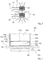
- FIG. 1 shows a cooking system 10 with a hob 34.
- the cooking system 10 has an erector 100 on.
- the positioning unit 100 has a base unit 12.
- the base unit 12 is part of the cooking system 10.
- the setting unit 100 has a cookware element 14.
- the cookware element 14 is part of the cooking system 10.
- the cooking system 10 has a cover plate 16.
- the hob 34 is disposed below the cover plate 16.
- the hob 34 is free from a hob plate in the present case.
- the cover plate 16 is formed differently from a cooktop panel.
- the cover 16 is designed as a kitchen worktop.
- a hob may comprise a hob plate, wherein a cover plate at least partially formed integrally with the hob plate and / or may be formed completely as a hob plate.
- the hob 34 has at least one induction heating unit 18.
- the induction heating unit 18 includes an induction heating element 28.
- the induction heating element 28 is provided for providing inductive energy.
- the induction heating element 28 is provided for heating a portion of the erection unit 100.
- the induction heating element 28 is provided for heating a cooking utensil element 14 of the setting-up unit 100.
- the induction heating element 28 is at a Transmission of inductive energy to the part of the Aufstellinheit 100, in particular to the cookware element 14, is provided.
- the induction heating element 28 is designed as an induction coil.
- the inductive energy is transmitted by means of a magnetic field 46 (cf. FIG. 3 ).
- the magnetic field 46 generates in the part of the setting-up unit 100, in particular in the cookware element 14, a heat energy for heating the part of the setting-up unit 100, in particular of the cookware element 14.
- the induction heating unit 18 comprises a plurality of further induction heating elements which are identical in construction to the induction heating element 28 are formed.
- the hob 34 has another induction heating unit 32.
- the induction heating unit 18 and the further induction heating unit 32 are of identical construction. A description of the induction heating unit 18 may be transmitted to the further induction heating unit 32.
- a hob may include other induction heating units.
- the cover plate 16 is provided for setting up the setting unit 100.
- the cover plate 16 is provided for setting up the base unit 12. In the heating operation state, the base unit 12 is disposed between the cover plate 16 and the cookware element 14.
- the cooking field 34 comprises a control unit 36.
- the control unit 36 is arranged below the cover plate 16. In the present case, the control unit 36 is arranged below the induction heating unit 18.
- the control unit 36 regulates in at least one heating operating state of the hob 34, a power supply to the induction heating units 18, 32.
- a control unit to an induction heating unit can also be arranged offset horizontally.
- the base unit 12 in the heating mode, substantially prevents transfer of heat from the cookware element 14 to the cover plate 16.
- the base unit 12 has a substantially disk-like shape. In the present embodiment, the base unit 12 has a diameter of substantially 180 mm.
- the base unit 12 has a thickness of substantially 2 mm.
- the base unit 12 consists for the most part of a substantially flexible material.
- the material of which the base unit 12 is largely made has a low thermal conductivity.
- the material from which the base unit 12 is largely made is substantially insulating and / or substantially easy to clean.
- the base unit 12 consists to a large extent of silicone.
- a base unit may be made of an elastic plastic and have a thickness of more than 2 mm or less than 2 mm.
- the set-up unit 100 has an electronic unit 40, as the detailed view of the base unit 12 in FIG. 2 shows.
- the base unit 12 the electronic unit 40.
- the electronics unit 40 provides at least one function in an operating state. Before starting the heating operation state, the electronics unit 40 provides several functions in the operating state.
- the electronics unit 40 is provided for a sensor function, for example of cookware parameters such as temperature, cooking time, cookware weight, and / or for a display and control function by means of an operating unit 42 and a display unit 44.
- the cooking system 10 has a positioning unit 20.
- the positioning unit 20 is partially disposed in and / or formed by the setting unit 100.
- the positioning unit 20 is partially arranged in the base unit 12 and / or formed by them.
- the positioning unit 20 is partially disposed in and / or formed by the induction heating unit 18.
- the positioning unit 20 is provided to assist positioning of the setting unit 100, particularly the base unit 12, relative to the induction heating unit 18.
- the positioning unit 20 is provided to assist in positioning the cookware element 14 relative to the base unit 12 and the induction heating unit 18.
- the positioning unit 20 has a positioning element 22.
- the positioning element 22 is associated with the setting-up unit 100, in particular the lower unit 12.
- the positioning element 22 is integrated in the setting-up unit 100, in particular in the base unit 12.
- the positioning element 22 is arranged in the set-up unit, in particular in the lower unit 12.
- the positioning element 22 is intended, at least partially, to assist the positioning of the setting-up unit 100, in particular the base unit 12 to contribute relative to the induction heating unit 18.
- the positioning element 22 is designed as an inductive element 24.
- the positioning element 22 is formed as a coil.
- the positioning unit 20 comprises a plurality of additional positioning elements.
- the additional positioning elements are associated with the setting-up unit 100, in particular the base unit 12.
- the additional positioning elements are integrated in the setting-up unit 100, in particular in the lower unit 12.
- the additional positioning elements are arranged in the setting-up unit 100, in particular in the base unit 12.
- the additional positioning elements are designed as inductive elements.
- the additional positioning elements are designed as coils.
- the additional positioning elements are constructed identical to the positioning element 22.
- the base unit 12 comprises five positioning elements.
- the positioning elements are in the present case concentric and regularly distributed over the base unit 12.
- positioning elements may also be designed differently, for example in a number of coil windings or a coil diameter or a coil outline shape.
- positioning elements can be arranged concentrically and / or be manufactured concentrically to an erection unit, in particular to a base unit. It is also possible to arrange the positioning elements irregularly in an erection unit, in particular in a lower unit.
- an erection unit, in particular a base unit have only one positioning element.
- the positioning unit 20 has a further positioning element 26.
- the further positioning element 26 is assigned to the induction heating unit 18.
- the further positioning element 26 is arranged in and / or formed by the induction heating unit 18.
- the further positioning element 26 is formed as a further inductive element.
- the further positioning element 26 is formed integrally with the induction heating element 28.
- the further positioning element 26 is formed as a coil.
- the further positioning element 26 is formed as a corresponding to the positioning element 22 further positioning element.
- the further positioning element 26 is corresponding to the additional positioning elements educated.
- the further positioning element 26 is intended to cooperate with the positioning element 22 for positioning the positioning unit 100, in particular the base unit 12, relative to the induction heating unit 18.
- the further positioning element 26 is provided to provide a magnetic field 46.
- the further positioning element 26 is provided to generate a magnetic field 46 by means of an applied electrical current 56.
- the further positioning element 26 forms a magnetic field 46 by means of the electrical current 56 flowing through the further positioning element 26.
- the magnetic field 46 is stronger in a geometric center of the further positioning element 26 than at the edges of the further positioning element 26.
- the further positioning element 26 is intended to assist in positioning the positioning unit 100, in particular the base unit 12, relative to the induction heating unit 18 to interact with the additional positioning elements.
- the positioning element 22 and the further positioning element 26 are inductively coupled to support the positioning.
- the positioning element 22 is coupled to a magnetic field 46 of the further positioning element 26.
- the magnetic field 46 of the further positioning element 26 passes through the positioning element 22.
- the magnetic field 46 induces an electrical current in the positioning element 22.
- the magnetic field 46 induces an induction current 52 in the positioning element 22.
- the magnetic field 46 in the positioning element 22 generates an electrical voltage.
- the magnetic field 46 generates an induction voltage 54 in the positioning element 22.
- the magnitude of the induction current 52 in the positioning element 22 is correlated with the strength of the magnetic field 46.
- the magnitude of the induction current 52 in the positioning element 22 is proportional to the strength of the magnetic field 46
- the magnitude of the induction voltage 54 in the positioning element 22 is correlated with the strength of the magnetic field 46.
- the induction current 52 and the induction voltage 54 are utilized as electrical energy to power the electronics unit 40.
- the induction current 52 forms a further magnetic field of the positioning element 22.
- the induction current 52 and the induction voltage 54 form an inductive conductance of the positioning element 22.
- the further positioning element 26 and the additional further positioning elements each induce an additional induction voltage in the additional positioning elements of the base unit 12.
- the sizes of the respective additional induction voltages are dependent on the positioning of the additional positioning elements relative to the other positioning elements and may differ from each other.
- the erection unit 100 in particular the base unit 12, comprises a measuring unit 48 (cf. FIG. 2 ).
- the measuring unit 48 is provided to measure the induction voltage 54 of the positioning element 22.
- the measuring unit 48 has a measuring element 50.
- the measuring element 50 is assigned to the positioning element 22.
- the measuring element 50 is provided to measure the induction voltage 54 of the positioning element 22.
- the measuring element 50 is designed as a measuring circuit.
- the measuring element 50 is adapted to the positioning element 22.
- the measuring element 50 is connected to the positioning element 22.
- the measuring unit 48 has a plurality of additional measuring elements. In each case one of the additional measuring elements is assigned to one of the additional positioning elements.
- the additional measuring elements are each intended to measure in each case one of the positioning elements in each case an induction voltage.
- the additional measuring elements are each designed as a measuring circuit. Each one of the additional measuring elements is adapted to each one of the additional positioning elements. In each case one of the additional measuring elements is connected to one of the additional positioning elements. Alternatively or additionally, it is conceivable that a measuring unit is provided for measuring an induction current and / or the induced magnetic fields of the positioning elements of a positioning unit, in particular a base unit.
- the cooking system 10 has a position indicating unit 30.
- the position indicating unit 30 is provided for indicating the positioning based on a magnitude of an inductive parameter of the positioning member 22.
- the position indicating unit 30 is provided for indicating the positioning based on a magnitude of the induction voltage 54 of the positioning member 22.
- the position indicating unit 30 is provided for indicating the positioning based on the magnitude of the additional induction voltage of the additional positioning elements.
- the position display unit 30 is preferably formed in the present case as an LED display.
- the position display unit 30 shows a positioning of the positioning member 22 by means of the induction voltage 54 and of the additional positioning element by means of the additional induction voltages.
- the position display unit 30 indicates a positioning of the setting unit 100, in particular the base unit 12, by means of the induction voltage 54 and the additional induction voltages.
- the position indicating unit 30 is integrated in the setting unit 100, in particular the base unit 12.
- the position display unit 30 is integrated in the display unit 44.
- the position indicating unit could also be integrated into a cover plate and communicate by means of a signal transmitter integrated in an erection unit, in particular in a base unit.
- the position display unit 30 is designed as an LED display and displays the position of the setting unit 100, in particular the base unit 12, for example by means of an LED array and / or a digital power display in the number format by one to the induction voltage 54 and the additional induction voltage corresponding heating power value is displayed as a value by means of the LED row and / or a percentage.
- a position indicating unit could indicate a directional indication in the form of aligned arrows indicating the direction of a position with a higher heating power value.
- a position display unit could be embodied as a display which displays color codes for heating power values, for example over a cutout and / or an entire support area of an erection unit, in particular a base unit, and / or indicates a direction to a position with a higher heating power value.
- FIG. 4 a further embodiment of the invention is shown. The following descriptions are essentially limited to the differences between the embodiments, with respect to the same components, features and functions on the description of the embodiment of FIGS. 1 to 3 can be referenced. To distinguish the embodiments, the reference numerals of the embodiment in the FIGS. 1 to 3 in the embodiment of FIG. 4 the letter b adjusted. With respect to identically designated components, in particular with regard to components with the same reference numerals, can in principle also to the drawings and / or the description of the embodiment of FIGS. 1 to 3 to get expelled.
- FIG. 4 shows an alternative cooking system 10b with a hob 34b.
- the cooking system 10b has an erector unit 100b.
- the setting-up unit 100b has a housing unit 104b.
- the housing unit 104b defines a receiving space 106b for receiving food, in particular for the purpose of cooking the food.
- a positioning member 22b of a positioning unit 20b of the cooking system 10b is partially integrated in the housing unit 104b.
- An operation unit 42b of the cooking system 10b is partially integrated in the housing unit 104b.
- the operating unit 42b has an operating element 108b, which is provided for actuation by an operator.
- the operating member 108b is fixed to the housing unit 104b in a heating operation state.
- the operating unit 42b has an operating electronics 110b which is provided for processing a signal received by the operating element. In the operating state, the operating element 108b and the operating electronics 110b in particular communicate wirelessly with one another.
- the operating electronics 110b is integrated in the housing unit 104b.
- the cooking system 10b has a display unit 44b, which is partially formed integrally with the control unit 42b.
- the cooking system 10b has a transmitting unit 112b.
- the transmitting unit 112b is integrated in the housing unit 104b.
- the transmission unit 112b is provided for communication with the positioning unit 20b of the cooking system 10b and / or with a control unit 36b of the cooking system 10b, which is integrated in particular in the hob 34b.
- the control unit 36b and the positioning unit 20b are partially formed in one piece.
- the control unit 36b is part of the positioning unit 20b.
- An induction heating unit 18b of the cooking system 10b is part of the positioning unit 20b.
- the induction heating unit 18b inductively supplies power to the setting-up unit 100b.
- the setting-up unit 100b has a receiving induction unit 114b, which is provided for receiving at least part of the energy inductively provided by the induction heating unit 18b.
- the pickup induction unit 114b has a pickup induction element 114b.
- the pickup induction element 114b is formed as a coil.
- the pickup induction unit 114b is provided with power to supply at least one of an electronic unit 40b and / or an operation unit 42b and / or a display unit 44b and / or a measurement unit 48b and / or the transmission unit 112b.
- the induction heating unit 18b heats a wall 116b of the housing unit 104b bounding the receiving space 106b by means of the energy in the heating operating state. In the heating operation state, the induction heating unit 18b transmits a part of the supplied power to the wall 116b of the housing unit 104b and a part of the power to the pickup induction unit 114b.
Landscapes
- Engineering & Computer Science (AREA)
- Physics & Mathematics (AREA)
- Electromagnetism (AREA)
- Chemical & Material Sciences (AREA)
- Combustion & Propulsion (AREA)
- Mechanical Engineering (AREA)
- General Engineering & Computer Science (AREA)
- Food Science & Technology (AREA)
- Induction Heating Cooking Devices (AREA)
- Electric Stoves And Ranges (AREA)
- Cookers (AREA)
- General Preparation And Processing Of Foods (AREA)
Abstract
Description
- Die Erfindung betrifft ein Kochsystem nach dem Anspruch 1 und ein Verfahren zu einer Positionierung einer Aufstelleinheit gemäß dem Anspruch 13.
- Aus dem Stand der Technik sind Kochsysteme mit zumindest einer Unterlegeinheit bekannt, welche zu einem Auflegen auf einer Abdeckplatte eines Kochfelds ausgebildet ist. Die Unterlegeinheit ist in einem Heizbetriebszustand zwischen der Abdeckplatte und einem beheizten Gargeschirr angeordnet. Das Kochsystem umfasst zudem eine Positionierungseinheit, welche zu einer Unterstützung einer Positionierung der Unterlegeinheit relativ zu der Induktionsheizeinheit vorgesehen ist, wobei zur Unterstützung der Positionierung der Unterlegeinheit ein Beschleunigungssensor und/oder eine Kamera des Kochsystems zum Einsatz kommt.
- Die Aufgabe der Erfindung besteht insbesondere darin, eine gattungsgemäße Vorrichtung mit verbesserten Eigenschaften hinsichtlich einer Positionierungsunterstützung bereitzustellen. Die Aufgabe wird erfindungsgemäß durch die Merkmale der Ansprüche 1 und 13 gelöst, während vorteilhafte Ausgestaltungen und Weiterbildungen der Erfindung den Unteransprüchen entnommen werden können.
- Die Erfindung betrifft ein Kochsystem mit zumindest einer Aufstelleinheit, welche in wenigstens einem Heizbetriebszustand zu einer Anordnung oberhalb einer Abdeckplatte vorgesehen ist, mit einer Induktionsheizeinheit, welche zu einer Erhitzung zumindest eines Teils der Aufstelleinheit vorgesehen ist, und mit einer Positionierungseinheit, welche zu einer Unterstützung einer Positionierung der Aufstelleinheit relativ zu der Induktionsheizeinheit vorgesehen ist.
- Die Positionierungseinheit weist wenigstens ein der Aufstelleinheit zugeordnetes Positionierungselement auf, welches als induktives Element ausgebildet und dazu vorgesehen ist, zumindest teilweise zu der Unterstützung der Positionierung der Aufstelleinheit relativ zu der Induktionsheizeinheit beizutragen. Durch diese Ausgestaltung kann insbesondere eine vorteilhafte Positionierungsunterstützung geschaffen werden. Ferner kann ein insbesondere von einer externen Energiequelle unabhängig betriebsbereites Positionierungselement bereitgestellt werden, wodurch insbesondere Energiekosten gesenkt werden können und vorteilhaft folglich auf eine kabelgestützte Verbindung mit einer externen Energiequelle verzichtet werden kann. Ferner kann insbesondere eine Anwendungsflexibilität verbessert und vorteilhaft ein Bedienkomfort erhöht werden. Zudem können vorteilhaft Material- und/oder Herstellungskosten sowie ein Wartungsaufwand gesenkt werden.
- Unter einer "Aufstelleinheit" soll insbesondere eine Einheit verstanden werden, welche zu einem Aufstellen und/oder Auflegen auf einer Abdeckplatte vorgesehen ist, und zwar insbesondere zum Zweck einer Beheizung zumindest eines Teils der Aufstelleinheit. Die Aufstelleinheit könnte beispielsweise zumindest ein Kochgeschirrelement aufweisen. Alternativ oder zusätzlich könnte die Aufstelleinheit zumindest eine Unterlegeinheit aufweisen, welche insbesondere zu einem Aufstellen zumindest eines Kochgeschirrelements, insbesondere des Kochgeschirrelements, vorgesehen sein könnte. Die Unterlegeinheit könnte beispielsweise in dem Heizbetriebszustand zu einer Anordnung zwischen einem zu erhitzenden Kochgeschirrelement der Aufstelleinheit und der Abdeckplatte vorgesehen sein. Insbesondere könnten Objekte der Aufstelleinheit, wie beispielsweise eine Bedieneinheit und/oder eine Steuereinheit und/oder eine Sensoreinheit und/oder eine Sendeeinheit, zumindest teilweise und vorteilhaft wenigstens zu einem Großteil in der Unterlegeinheit integriert sein.
- Unter einer "Unterlegeinheit" soll insbesondere eine Einheit verstanden werden, welche insbesondere zu einem Auflegen, insbesondere zu einer Platzierung und/oder Positionierung, auf der Abdeckplatte des Kochsystems, insbesondere eines Kochfelds des Kochsystems, und zu einem Aufstellen zumindest eines Kochgeschirrelements vorgesehen ist und welche insbesondere in dem Heizbetriebszustand eine Unterlage für das beheizte Kochgeschirrelement wenigstens teilweise ausbildet. In einer Einbaulage ist die Unterlegeinheit insbesondere zu einer Platzierung oberhalb eines Kochfelds, insbesondere oberhalb der Abdeckplatte, vorgesehen. Die Abdeckplatte ist insbesondere als Küchenarbeitsplatte ausgebildet.
- Alternativ, insbesondere zu der Ausgestaltung, in welcher die Aufstelleinheit zumindest eine Unterlegeinheit und insbesondere zumindest ein Kochgeschirrelement aufweist, könnte die Aufstelleinheit beispielsweise zumindest eine Gehäuseeinheit aufweisen, welche insbesondere als eine Außengehäuseeinheit ausgebildet sein und insbesondere ein Außengehäuse der Aufstelleinheit wenigstens zu einem Großteil ausbilden könnte. Insbesondere könnte zumindest ein Objekt der Aufstelleinheit, insbesondere mehrere Objekte der Aufstelleinheit und vorteilhaft alle Objekte der Aufstelleinheit, wie beispielsweise eine Bedieneinheit und/oder eine Steuereinheit und/oder eine Sensoreinheit und/oder eine Sendeeinheit, zumindest teilweise und vorteilhaft wenigstens zu einem Großteil in der Gehäuseeinheit integriert sein. Unter "wenigstens zu einem Großteil" soll insbesondere zu einem Anteil, insbesondere einem Massenanteil und/oder Volumenanteil, von mindestens 70 %, insbesondere von mindestens 80 %, vorteilhaft von mindestens 90 % und vorzugsweise von mindestens 95 % verstanden werden.
- Das Kochsystem weist insbesondere das Kochfeld auf. Unter einem "Kochfeld" soll insbesondere eine Einheit verstanden werden, welche zumindest eine Induktionsheizeinheit, eine Versorgungseinheit und eine Elektronikeinheit des Kochfelds aufweist, welche insbesondere dazu vorgesehen ist, in dem Heizbetriebszustand eine Versorgungseinheit insbesondere zu einer Versorgung der Induktionsheizeinheit mit Energie, insbesondere mit elektrischer Energie, anzusteuern, wobei die Induktionsheizeinheit in dem Heizbetriebszustand in Abhängigkeit einer Versorgung durch die Versorgungseinheit insbesondere zu einer Bereitstellung von Energie, insbesondere von elektromagnetischer Energie, insbesondere induktiver Energie, an zumindest einen Teil der Aufstelleinheit, insbesondere an wenigstens ein Kochgeschirrelement, insbesondere an das Kochgeschirrelement, der Aufstelleinheit und/oder von zumindest einer Wandung einer Gehäuseeinheit der Aufstelleinheit, vorgesehen ist.
- Das Kochfeld kann insbesondere eine Kochfeldplatte aufweisen, wobei die Abdeckplatte zumindest teilweise einstückig mit der Kochfeldplatte ausgebildet und/oder vollständig als Kochfeldplatte ausgebildet sein kann. Die Aufstelleinheit, insbesondere die Unterlegeinheit der Aufstelleinheit, ist insbesondere von dem Kochfeld, insbesondere von der Abdeckplatte, verschieden und/oder vorteilhaft relativ zu dem Kochfeld, insbesondere zu der Abdeckplatte, beweglich. Insbesondere ist die Aufstelleinheit, insbesondere Unterlegeinheit der Aufstelleinheit, als eine separate Einheit ausgebildet. Insbesondere kann eine als separate Einheit ausgebildete Aufstelleinheit und/oder Unterlegeinheit an einer beliebigen Position auf der Abdeckplatte positioniert werden. Unter einer "Abdeckplatte" soll insbesondere ein Element verstanden werden, welches dazu vorgesehen ist, wenigstens eine Heizeinheit, welche insbesondere in dem Heizbetriebszustand zu einer, vorteilhaft induktiven, Erhitzung des Kochgeschirrelements vorgesehen ist, zumindest teilweise, vorzugsweise wenigstens zu einem Großteil und besonders bevorzugt vollständig, abzudecken. Die Abdeckplatte kann insbesondere als Kochfeldplatte, wie beispielsweise als Glaskeramikplatte, und/oder als Arbeitsplatte, wie beispielsweise als Küchenarbeitsplatte, ausgebildet sein.
- Insbesondere ist die Aufstelleinheit, insbesondere die Unterlegeinheit, der Aufstelleinheit, zu einer Verwendung mit dem Kochfeld und vorzugsweise mit verschiedenen Kochfeldern vorgesehen. Das Kochfeld ist insbesondere zu einer Verwendung mit zumindest einer Aufstelleinheit, insbesondere mit zumindest einer Unterlegeinheit und/oder mit zumindest einem Kochgeschirrelement und/oder mit zumindest einer Gehäuseeinheit der Aufstelleinheit, und vorteilhaft wenigstens im Wesentlichen zeitgleich mit zumindest zwei, vorteilhaft mit zumindest drei und vorzugsweise mit zumindest vier Aufstelleinheiten, insbesondere Unterlegeinheiten und/oder Kochgeschirrelementen und/oder Gehäuseeinheiten der Aufstelleinheit, vorgesehen. Das Kochfeld ist vorzugweise als ein Matrixkochfeld ausgebildet. Unter der Wendung, dass das Kochfeld zu einer Verwendung "wenigstens im Wesentlichen" zeitgleich mit zumindest zwei Aufstelleinheiten vorgesehen ist, soll insbesondere verstanden werden, dass das Kochfeld in zumindest einem Zeitabschnitt zu einer Verwendung mit den Aufstelleinheiten vorgesehen ist, wobei insbesondere das Kochfeld in zumindest einem weiteren Zeitabschnitt zu einer Verwendung mit insbesondere genau einer Aufstelleinheit vorgesehen sein könnte.
- Die Induktionsheizeinheit ist insbesondere dazu vorgesehen, mittels zumindest eines Induktionsheizelements, welches insbesondere als eine Spule ausgebildet ist, vorzugsweise mittels einer Mehrzahl von Induktionsheizelementen eine elektrische Energie in eine induktive Energie umzuwandeln und der Aufstelleinheit, insbesondere dem Kochgeschirrelement und/oder zumindest einer Wandung der Gehäuseeinheit, zu einer Umwandlung in Wärme zuzuführen. Insbesondere bildet die Unterlegeinheit die Unterlage für das beheizte Kochgeschirrelement wenigstens im Wesentlichen aus. Die Unterlegeinheit weist insbesondere eine wenigstens im Wesentlichen plattenförmige Gestalt auf.
- Unter einer "Positionierungseinheit" soll insbesondere eine Einheit verstanden werden, welche in zumindest einem Betriebszustand eine Position der Aufstelleinheit relativ zur Induktionsheizeinheit erkennt und insbesondere zur Weiterverarbeitung bereitstellt, insbesondere anzeigt. Darunter, dass "das Positionierungselement zumindest teilweise zur Unterstützung der Positionierung einer Einheit vorgesehen ist", soll hier insbesondere verstanden werden, dass das Positionierungselement insbesondere einen Teil einer Positionierungseinheit ausbildet und zumindest zu einer Unterstützung der Positionierung der Einheit relativ zu dem Kochfeld beiträgt.
- Unter "vorgesehen" soll insbesondere speziell ausgelegt und/oder ausgestattet verstanden werden. Darunter, dass ein Objekt zu einer bestimmten Funktion vorgesehen ist, soll insbesondere verstanden werden, dass das Objekt diese bestimmte Funktion in zumindest einem Anwendungs- und/oder Betriebszustand erfüllt und/oder ausführt.
- Das Positionierungselement ist zumindest teilweise in der Aufstelleinheit, insbesondere in der Unterlegeinheit und/oder in dem Kochgeschirrelement und/oder in der Gehäuseeinheit, integriert. Dadurch kann insbesondere ein kompaktes und vorteilhaft bauraumsparendes Positionierungselement erhalten und vorteilhaft Material- und/oder Herstellungskosten reduziert werden. Darunter, dass "das Positionierungselement in einer Einheit integriert ist", soll insbesondere verstanden werden, dass die Einheit zumindest bereichsweise und/oder abschnittsweise, insbesondere wenigstens zu einem Großteil und vorteilhaft vollständig das Positionierungselement umgreift und/oder formschlüssig umgibt. Insbesondere ist das Positionierungselement vollständig in der Einheit integriert. Unter der Wendung, dass das Positionierungselement "zumindest teilweise" in einer Einheit integriert ist, soll insbesondere verstanden werden, dass das Positionierungselement zumindest ein Element aufweist, welches in der Einheit integriert ist, und beispielsweise zumindest ein weiteres Element aufweisen könnte, welches von dem Element verschieden sein könnte und welches insbesondere außerhalb der Einheit und/oder getrennt von der Einheit angeordnet sein könnte.
- Ferner wird vorgeschlagen, dass die Aufstelleinheit zumindest eine Unterlegeinheit aufweist, welche in dem Heizbetriebszustand zu einer Anordnung zwischen einem zu erhitzenden Kochgeschirrelement der Aufstelleinheit und der Abdeckplatte vorgesehen ist.
- Dadurch kann insbesondere eine besonders hohe Flexibilität erreicht werden. Insbesondere kann die Abdeckplatte vor einer Beschädigung geschützt werden, welche beispielsweise durch ein heißes Kochgeschirrelement und/oder durch Verschieben des Kochgeschirrelements auf der Abdeckplatte hervorgerufen sein könnte.
- Zudem wird vorgeschlagen, dass das Positionierungselement dazu vorgesehen ist, zumindest teilweise zu einer Unterstützung einer Positionierung einer Unterlegeinheit der Aufstelleinheit relativ zu der Induktionsheizeinheit beizutragen. Dadurch kann insbesondere eine vorteilhafte Positionierungsunterstützung geschaffen werden.
- In einer bevorzugten Ausgestaltung der Erfindung wird vorgeschlagen, dass das Positionierungselement als Spule ausgebildet ist. Dadurch kann insbesondere eine induktive Energie aus der Induktionsheizeinheit auf das Positionierungselement übertragen werden, wodurch insbesondere Energiekosten reduziert werden können. Zudem ist eine Kommunikation des Positionierungselements mit der Induktionsheizeinheit mittels eines induktiven Signals vorteilhaft verbessert.
- Zu einer verbesserten Positionierung der Aufstelleinheit, insbesondere der Unterlegeinheit und/oder des Kochgeschirrelements und/oder der Gehäuseeinheit, wird in einer bevorzugten Ausgestaltung der Erfindung vorteilhaft vorgeschlagen, dass die Positionierungseinheit wenigstens ein der Induktionsheizeinheit zugeordnetes und zu dem Positionierungselement korrespondierendes weiteres Positionierungselement aufweist, welches dazu vorgesehen ist, zu der Unterstützung der Positionierung der Aufstelleinheit, insbesondere der Unterlegeinheit und/oder des Kochgeschirrelements und/oder der Gehäuseeinheit, relativ zu der Induktionsheizeinheit mit dem Positionierungselement zusammenzuwirken. Dadurch kann insbesondere eine Positionierung der Aufstelleinheit, insbesondere der Unterlegeinheit und/oder des Kochgeschirrelements und/oder der Gehäuseeinheit, relativ zu der Induktionsheizeinheit und eine Erkennung der Positionierung verbessert werden und eine Kompatibilität der Positionierungseinheit erhöht werden. Insbesondere ist das weitere Positionierungselement in der Induktionsheizeinheit zumindest teilweise, vorteilhaft vollständig integriert.
- Zudem wird vorgeschlagen, dass die Induktionsheizeinheit wenigstens ein Induktionsheizelement, insbesondere eine Heizspule, aufweist, mit welchem das weitere Positionierungselement zumindest teilweise einstückig ausgebildet ist. Unter "zumindest teilweise einstückig" soll in diesem Zusammenhang insbesondere verstanden werden, dass zumindest ein Bauteil zumindest eines Objekts, insbesondere das Induktionsheizelement, einstückig mit zumindest einem Bauteil zumindest eines weiteren Objekts, insbesondere dem weiteren Positionierungselement, einstückig ausgebildet ist. Insbesondere ist das weitere Positionierungselement zumindest teilweise als Induktionsheizelement ausgebildet. Vorteilhaft sind das Positionierungselement und das Induktionsheizelement identisch. Dadurch kann vorteilhaft ein bauraumsparendes weiteres Positionierungselement erreicht und Material- und/oder Herstellungskosten reduziert werden.
- Zu einer verbesserten Positionierung durch die Positionierungseinheit wird vorgeschlagen, dass das Positionierungselement dazu vorgesehen ist, mit dem weiteren Positionierungselement zur Unterstützung der Positionierung induktiv zu koppeln. Dadurch kann insbesondere eine Übertragung eines insbesondere induktiven Signals, insbesondere eines magnetischen Felds, und ein Betrieb zur Positionierungsunterstützung vorteilhaft verbessert werden. Insbesondere soll unter "induktiv gekoppelt" in diesem Zusammenhang insbesondere verstanden werden, dass ein induktives Signal eines ersten Objekts, insbesondere ein magnetisches Feld des weiteren Positionierungselements, in dem Positionierungselement einen elektrischen Strom, insbesondere einen Induktionsstrom, und/oder eine elektrische Spannung, insbesondere eine Induktionsspannung, induziert. Insbesondere ist das weitere Positionierungselement dazu vorgesehen, ein induktives Signal, insbesondere ein magnetisches Feld, zu erzeugen, welches in dem Positionierungselement eine Spannung und/oder einen Strom induziert, wobei die induzierte Spannung und/oder der induzierte Strom mit dem induktiven Parameter, insbesondere dem zuvor bereits erwähnten induktiven Leitwert, des Positionierungselements korreliert sind. Alternativ könnte jedoch auch ein induktives Signal, insbesondere ein magnetisches Feld, in dem Positionierungselement einen Strom und/oder eine Spannung in dem weiteren Positionierungselement induzieren.
- Zudem wird vorgeschlagen, dass das Kochsystem eine Positionsanzeigeeinheit aufweist, welche zur Anzeige der Positionierung anhand einer Größe eines induktiven, insbesondere des zuvor bereits eingeführten Parameters des Positionierungselements vorgesehen ist. Insbesondere weist die Positionsanzeigeeinheit zumindest ein Positionsanzeigeelement auf, welches insbesondere mittels einer analogen Anzeige und insbesondere mittels eines Display-Anzeigeelements und/oder eines LED-Anzeigeelements eine Position beispielsweise durch die Anzeige einer Leistung anhand eines Betrags des induktiven Parameters in einer, zum Betrag des induktiven Parameters korrespondierenden LED-Reihe und/oder einer Richtungsanzeige oder einer Positionsanzeige, in welcher eine Heizleistung farblich kodiert in einer zweidimensionalen Darstellung im Bereich der Positionierungseinheit, insbesondere der Aufstelleinheit, vorteilhaft der Unterlegeinheit und/oder des Kochgeschirrelements und/oder der Gehäuseeinheit, anzeigt. Insbesondere ist der induktive Parameter korreliert mit dem zuvor bereits eingeführten induktiven Leitwert, insbesondere mit der Induktionsspannung. Insbesondere weist das Kochsystem zusätzlich eine Messeinheit mit zumindest einem Messelement auf, welches insbesondere dazu vorgesehen ist, den induktiven Parameter, insbesondere die Induktionsspannung, des Positionierungselements zu messen. Insbesondere ist jedem Positionierungselement zumindest ein Messelement zugeordnet, welches jeweils insbesondere als ein Messschaltkreis ausgebildet ist. Insbesondere ist die Positionsanzeigeeinheit zu einer Anzeige der Positionierung insbesondere des Positionierungselements relativ zu der Induktionsheizeinheit, insbesondere zu dem weiteren Positionierungselement der Positionierungseinheit, insbesondere mittels des induktiven Leitwerts, vorgesehen und insbesondere als analoge Anzeige, als Display-Anzeige und/oder vorzugsweise als LED-Anzeige ausgebildet und insbesondere an der Aufstelleinheit, insbesondere an der Unterlegeinheit und/oder an dem Kochgeschirrelement und/oder an der Gehäuseeinheit, angeordnet, insbesondere in die Aufstelleinheit, insbesondere in die Unterlegeinheit und/oder in das Kochgeschirrelement und/oder in die Gehäuseeinheit, zumindest teilweise integriert. Dadurch kann eine Positionierung insbesondere durch einen Benutzer ausgeführt und damit vorteilhaft ein Bedienkomfort erhöht werden.
- Um vorteilhaft eine Flexibilität der Aufstelleinheit, insbesondere der Unterlegeinheit und/oder des Kochgeschirrelements und/oder der Gehäuseeinheit, und insbesondere eine verbesserte, insbesondere genauere, Positionierung zu erreichen, wird zudem vorgeschlagen, dass die Positionierungseinheit eine Mehrzahl an Positionierungselementen umfasst, welche der Aufstelleinheit, insbesondere der Unterlegeinheit und/oder dem Kochgeschirrelement und/oder der Gehäuseeinheit, zugeordnet sind und zumindest im Wesentlichen und vorzugsweise vollständig baugleich zu dem Positionierungselement ausgebildet sind. Insbesondere umfasst die Positionierungseinheit eine Mehrzahl an Positionierungselementen, welche einer Aufstelleinheit, insbesondere einer Unterlegeeinheit und/oder einem Kochgeschirrelement und/oder einer Gehäuseeinheit einer Aufstelleinheit, zugeordnet sind, und eine Mehrzahl an weiteren Positionierungselementen, welche der Induktionsheizeinheit zugeordnet sind. Insbesondere sind das zumindest eine Positionierungselement und ein weiteres Positionierungselement induktiv gekoppelt. Insbesondere sind eine Mehrzahl von Positionierungselementen und ein Mehrzahl von weiteren Positionierungselementen induktiv gekoppelt. Unter "zumindest im Wesentlichen baugleich" soll in diesem Zusammenhang insbesondere verstanden werden, dass sich eines der Positionierungselemente hinsichtlich einer Außenform und/oder eines kleinsten, die Außenform umfassenden Volumens um höchstens 30 %, vorteilhaft um höchstens 20 %, bevorzugt um höchstens 10 % und besonders vorteilhaft um höchstens 5 % sowie hinsichtlich einer Masse um höchstens 30 %, vorteilhaft um höchstens 20 %, bevorzugt um höchstens 10 % und besonders vorteilhaft um höchstens 5 % von den Positionierungselementen unterscheidet.
- Für eine verbesserte Positionierung und einen vorteilhaft verbesserten Bedienkomfort wird weiterhin vorgeschlagen, dass die Aufstelleinheit ein Kochgeschirrelement aufweist, wobei die Positionierungseinheit zu einer Unterstützung einer Positionierung des Kochgeschirrelements relativ zu einer Unterlegeinheit der Aufstelleinheit und der Induktionsheizeinheit vorgesehen ist. Insbesondere ist die Positionierung des Kochgeschirrelements relativ zu der Unterlegeinheit mittels einer zusätzlichen Bestimmung eines weiteren induktiven Parameters, welcher eine Änderung der Spannung und/oder des Stroms durch eine relative Positionierung der Unterlegeinheit zum Kochgeschirrelement bewirkt. Insbesondere korreliert der weitere induktive Parameter mit dem induktiven Leitwert und hat einen insbesondere vom induktiven Parameter verschiedenen Wert.
- Weiterhin wird vorgeschlagen, dass die Aufstelleinheit zumindest eine Gehäuseeinheit aufweist, in welcher das Positionierungselement zumindest teilweise und vorteilhaft wenigstens zu einem Großteil integriert ist. Dadurch kann insbesondere eine geringe Bauteilevielfalt und/oder eine geringe Lagerhaltung und/oder eine unkomplizierte Ausgestaltung erzielt werden. Die Gehäuseeinheit könnte beispielsweise mehrteilig ausgebildet sein, wobei insbesondere Teilbereiche der Gehäuseeinheit in dem Heizbetriebszustand miteinander insbesondere lösbar verbunden sein könnten. Hierdurch könnte insbesondere im Fall eines Defekts ein Zugriff auf zumindest ein in der Gehäuseeinheit integriertes Objekt ermöglicht werden. Alternativ könnte die Gehäuseeinheit einstückig ausgebildet sein, wodurch insbesondere eine hohe Stabilität erzielt werden könnte. Unter "einstückig" soll insbesondere zumindest stoffschlüssig verbunden verstanden werden, beispielsweise durch einen Schweißprozess, einen Klebeprozess, einen Anspritzprozess und/oder einen anderen, dem Fachmann als sinnvoll erscheinenden Prozess, und/oder vorteilhaft in einem Stück geformt verstanden werden, wie beispielsweise durch eine Herstellung aus einem Guss und/oder durch eine Herstellung in einem Ein- oder Mehrkomponentenspritzverfahren und vorteilhaft aus einem einzelnen Rohling.
- Zudem wird ein Verfahren zu einer Positionierung einer Aufstelleinheit, insbesondere einer Unterlegeinheit und/oder eines Kochgeschirrelements und/oder einer Gehäuseeinheit der Aufstelleinheit, insbesondere eines Kochsystems mit einer Positionierungseinheit, vorgeschlagen, welche zu einer Unterstützung einer Positionierung einer Aufstelleinheit, insbesondere einer Unterlegeinheit und/oder eines Kochgeschirrelements und/oder einer Gehäuseeinheit der Aufstelleinheit, relativ zu einer Induktionsheizeinheit vorgesehen ist und welche wenigstens ein der Aufstelleinheit, insbesondere der Unterlegeinheit und/oder dem Kochgeschirrelement und/oder der Gehäuseeinheit, zugeordnetes Positionierungselement aufweist, welches als induktives Element ausgebildet ist, wobei mittels des Positionierungselements zumindest teilweise zu der Unterstützung der Positionierung der Aufstelleinheit, insbesondere der Unterlegeinheit und/oder dem Kochgeschirrelement und/oder der Gehäuseeinheit, relativ zu der Induktionsheizeinheit beigetragen wird, und wobei das Positionierungselement zumindest teilweise in der Aufstelleinheit integriert ist. Dadurch kann eine von einer Energiequelle unabhängig betriebsbereite Positionierung mittels des Positionierungselements bereitgestellt werden, wodurch vorteilhaft Energiekosten gesenkt werden können und vorteilhaft folglich auf eine kabelgestützte Verbindung mit einer externen Energiequelle verzichtet werden kann. Ferner kann insbesondere eine Anwendungsflexibilität verbessert und vorteilhaft ein Bedienkomfort erhöht werden. Zudem können vorteilhaft Material- und/oder Herstellungskosten sowie ein Wartungsaufwand gesenkt werden.
- Weitere Vorteile ergeben sich aus der folgenden Zeichnungsbeschreibung. In der Zeichnungen ist ein Ausführungsbeispiel der Erfindung dargestellt. Die Zeichnungen, die Beschreibung und die Ansprüche enthalten zahlreiche Merkmale in Kombination. Der Fachmann wird die Merkmale zweckmäßigerweise auch einzeln betrachten und zu sinnvollen weiteren Kombinationen zusammenfassen.
- Es zeigen:
- Fig. 1
- ein Kochsystem mit einem Kochfeld, mit einer Aufstelleinheit, welche eine Unterlegeeinheit und ein Kochgeschirrelement aufweist, und einer Positionierungseinheit in einer schematischen Darstellung,
- Fig. 2
- die Unterlegeinheit mit einer Mehrzahl an Positionierungselementen,
- Fig. 3
- eine schematische Abbildung einer Übertragung an induktiver Energie von einer Induktionsheizeinheit auf ein Positionierungselement und
- Fig. 4
- ein alternatives Kochsystem umfassend eine Aufstelleinheit, welche eine Gehäuseeinheit aufweist, ein Kochfeld und eine Positionierungseinheit in einer schematischen Darstellung.
-
Figur 1 zeigt ein Kochsystem 10 mit einem Kochfeld 34. Das Kochsystem 10 weist eine Aufstelleinheit 100 auf. Im vorliegenden Ausführungsbeispiel weist die Aufstelleinheit 100 eine Unterlegeinheit 12 auf. Die Unterlegeinheit 12 ist Teil des Kochsystems 10. Die Aufstelleinheit 100 weist ein Kochgeschirrelement 14 auf. Das Kochgeschirrelement 14 ist Teil des Kochsystems 10. - Das Kochsystem 10 weist eine Abdeckplatte 16 auf. In einem montierten Zustand ist das Kochfeld 34 unterhalb der Abdeckplatte 16 angeordnet. Das Kochfeld 34 ist im vorliegenden Fall frei von einer Kochfeldplatte. Die Abdeckplatte 16 ist verschieden von einer Kochfeldplatte ausgebildet. Die Abdeckplatte 16 ist als Küchenarbeitsplatte ausgebildet. Alternativ oder zusätzlich kann ein Kochfeld eine Kochfeldplatte aufweisen, wobei eine Abdeckplatte zumindest teilweise einstückig mit der Kochfeldplatte ausgebildet und/oder vollständig als Kochfeldplatte ausgebildet sein kann.
- Das Kochfeld 34 weist zumindest eine Induktionsheizeinheit 18 auf. Die Induktionsheizeinheit 18 umfasst ein Induktionsheizelement 28. Das Induktionsheizelement 28 ist zu einer Bereitstellung von induktiver Energie vorgesehen. Das Induktionsheizelement 28 ist zu einer Erhitzung eines Teils der Aufstelleinheit 100 vorgesehen. Im vorliegenden Ausführungsbeispiel ist das Induktionsheizelement 28 zu einer Erhitzung eines Kochgeschirrelements 14 der Aufstelleinheit 100 vorgesehen. Das Induktionsheizelement 28 ist zu einer Übertragung von induktiver Energie an den Teil der Aufstelleinheit 100, insbesondere an das Kochgeschirrelement 14, vorgesehen. Das Induktionsheizelement 28 ist als Induktionsspule ausgebildet. Die Induktive Energie wird mittels eines magnetischen Felds 46 übertragen (vgl.
Figur 3 ). Das magnetische Feld 46 erzeugt in dem Teil der Aufstelleinheit 100, insbesondere in dem Kochgeschirrelement 14, eine Wärmeenergie zur Erhitzung des Teils der Aufstelleinheit 100, insbesondere des Kochgeschirrelements 14. Zudem umfasst die Induktionsheizeinheit 18 eine Mehrzahl an weiteren Induktionsheizelementen, welche baugleich zu dem Induktionsheizelement 28 ausgebildet sind. Zusätzlich weist das Kochfeld 34 eine weitere Induktionsheizeinheit 32 auf. Die Induktionsheizeinheit 18 und die weitere Induktionsheizeinheit 32 sind baugleich ausgebildet. Eine Beschreibung der Induktionsheizeinheit 18 kann auf die weitere Induktionsheizeinheit 32 übertragen werden. - Ein Oberflächenbereich der Abdeckplatte 16, unterhalb welcher das Kochfeld 34 angeordnet ist, definiert einen Kochbereich. Zusätzlich kann ein Kochfeld weitere Induktionsheizeinheiten umfassen. Die Abdeckplatte 16 ist zu einem Aufstellen der Aufstelleinheit 100 vorgesehen. Im vorliegenden Ausführungsbeispiel ist die Abdeckplatte 16 zu einem Aufstellen der Unterlegeinheit 12 vorgesehen. In dem Heizbetriebszustand ist die Unterlegeinheit 12 zwischen der Abdeckplatte 16 und dem Kochgeschirrelement 14 angeordnet.
- Das Kochfeld 34 umfasst eine Steuereinheit 36. Die Steuereinheit 36 ist unterhalb der Abdeckplatte 16 angeordnet. Im vorliegenden Fall ist die Steuereinheit 36 unterhalb der Induktionsheizeinheit 18 angeordnet. Die Steuereinheit 36 regelt in zumindest einem Heizbetriebszustand des Kochfelds 34 eine Energiezufuhr zu den Induktionsheizeinheiten 18, 32. Alternativ kann eine Steuereinheit zu einer Induktionsheizeinheit auch horizontal versetzt angeordnet sein.
- Die Unterlegeinheit 12 verhindert in dem Heizbetriebszustand im Wesentlichen eine Übertragung von Wärme von dem Kochgeschirrelement 14 auf die Abdeckplatte 16. Die Unterlegeinheit 12 weist eine im Wesentlichen scheibenförmige Gestalt auf. Im vorliegenden Ausführungsbeispiel weist die Unterlegeinheit 12 einen Durchmesser von im Wesentlichen 180 mm auf. Die Unterlegeinheit 12 weist eine Dicke von im Wesentlichen 2 mm auf.
- Die Unterlegeinheit 12 besteht zu einem Großteil aus einem im Wesentlichen flexiblen Material. Das Material, aus welchem die Unterlegeinheit 12 zu einem Großteil besteht, weist eine geringe Wärmeleitfähigkeit auf. Insbesondere ist das Material, aus welchem die Unterlegeinheit 12 zu einem Großteil besteht, im Wesentlichen isolierend und/oder im Wesentlichen einfach zu reinigen. Im vorliegenden Ausführungsbeispiel besteht die Unterlegeinheit 12 zu einem Großteil aus Silikon. Alternativ kann eine Unterlegeinheit aus einem elastischen Plastik bestehen und eine Dicke von mehr als 2 mm oder weniger als 2 mm aufweisen.
- Die Aufstelleinheit 100 weist eine Elektronikeinheit 40 auf, wie die Detailansicht der Unterlegeinheit 12 in
Figur 2 zeigt. Im vorliegenden Ausführungsbeispiel weist die Unterlegeinheit 12 die Elektronikeinheit 40 auf. Die Elektronikeinheit 40 stellt in einem Betriebszustand zumindest eine Funktion bereit. Vor einem Beginn des Heizbetriebszustands stellt die Elektronikeinheit 40 in dem Betriebszustand mehrere Funktionen bereit. Die Elektronikeinheit 40 ist zu einer Sensorfunktion, beispielweise von Kochgeschirrparametern wie Temperatur, Kochdauer, Kochgeschirrgewicht, und/oder zu einer Anzeigen- und Bedienungsfunktion mittels einer Bedieneinheit 42 und einer Anzeigeeinheit 44 vorgesehen. - Im vorliegenden Fall weist das Kochsystem 10 eine Positionierungseinheit 20 auf. Die Positionierungseinheit 20 ist teilweise in der Aufstelleinheit 100 angeordnet und/oder durch diese gebildet. Im vorliegenden Ausführungsbeispiel ist die Positionierungseinheit 20 teilweise in der Unterlegeinheit 12 angeordnet und/oder durch diese gebildet. Die Positionierungseinheit 20 ist teilweise in der Induktionsheizeinheit 18 angeordnet und/oder durch diese gebildet. Die Positionierungseinheit 20 ist zu einer Unterstützung einer Positionierung der Aufstelleinheit 100, insbesondere der Unterlegeinheit 12, relativ zu der Induktionsheizeinheit 18 vorgesehen. Die Positionierungseinheit 20 ist zu einer Unterstützung einer Positionierung des Kochgeschirrelements 14 relativ zu der Unterlegeinheit 12 und der Induktionsheizeinheit 18 vorgesehen. Die Positionierungseinheit 20 weist ein Positionierungselement 22 auf. Das Positionierungselement 22 ist der Aufstelleinheit 100, insbesondere der Unterlegeinheit 12, zugeordnet. Das Positionierungselement 22 ist in die Aufstelleinheit 100, insbesondere in die Unterlegeinheit 12, integriert. Das Positionierungselement 22 ist in der Aufstelleinheit, insbesondere in der Unterlegeinheit 12, angeordnet. Das Positionierungselement 22 ist dazu vorgesehen, zumindest teilweise zu der Unterstützung der Positionierung der Aufstelleinheit 100, insbesondere der Unterlegeinheit 12, relativ zu der Induktionsheizeinheit 18 beizutragen. Das Positionierungselement 22 ist als ein induktives Element 24 ausgebildet. Das Positionierungselement 22 ist als eine Spule ausgebildet.
- Die Positionierungseinheit 20 umfasst eine Mehrzahl an zusätzlichen Positionierungselementen. Die zusätzlichen Positionierungselemente sind der Aufstelleinheit 100, insbesondere der Unterlegeinheit 12, zugeordnet. Die zusätzlichen Positionierungselemente sind in die Aufstelleinheit 100, insbesondere in die Unterlegeinheit 12, integriert. Die zusätzlichen Positionierungselemente sind in der Aufstelleinheit 100, insbesondere in der Unterlegeinheit 12, angeordnet. Die zusätzlichen Positionierungselemente sind als induktive Elemente ausgebildet. Die zusätzlichen Positionierungselemente sind als Spulen ausgebildet. Die zusätzlichen Positionierungselemente sind baugleich zu dem Positionierungselement 22 ausgebildet. Im vorliegenden Fall umfasst die Unterlegeinheit 12 fünf Positionierungselemente. Die Positionierungselemente sind im vorliegenden Fall konzentrisch und regelmäßig über die Unterlegeinheit 12 verteilt.
- Alternativ können Positionierungselemente auch verschieden ausgebildet sein, beispielsweise in einer Zahl der Spulenwindungen oder eines Spulendurchmessers oder einer Spulenumrissform. Beispielsweise können Positionierungselemente konzentrisch angeordnet und/oder konzentrisch zu einer Aufstelleinheit, insbesondere zu einer Unterlegeinheit, gefertigt sein. Es ist auch möglich, die Positionierungselemente unregelmäßig in einer Aufstelleinheit, insbesondere in einer Unterlegeinheit anzuordnen. Alternativ kann eine Aufstelleinheit, insbesondere eine Unterlegeinheit, nur ein Positionierungselement aufweisen.
- Die Positionierungseinheit 20 weist ein weiteres Positionierungselement 26 auf. Das weitere Positionierungselement 26 ist der Induktionsheizeinheit 18 zugeordnet. Das weitere Positionierungselement 26 ist in der Induktionsheizeinheit 18 angeordnet und/oder durch diese gebildet. Das weitere Positionierungselement 26 ist als ein weiteres induktives Element ausgebildet. Das weitere Positionierungselement 26 ist einstückig mit dem Induktionsheizelement 28 ausgebildet. Das weitere Positionierungselement 26 ist als Spule ausgebildet. Das weitere Positionierungselement 26 ist als ein zu dem Positionierungselement 22 korrespondierendes weiteres Positionierungselement ausgebildet. Das weitere Positionierungselement 26 ist korrespondierend zu den zusätzlichen Positionierungselementen ausgebildet. Das weitere Positionierungselement 26 ist dazu vorgesehen, zu einer Positionierung der Aufstelleinheit 100, insbesondere der Unterlegeinheit 12, relativ zu der Induktionsheizeinheit 18 mit dem Positionierungselement 22 zusammenzuwirken. Das weitere Positionierungselement 26 ist dazu vorgesehen, ein magnetisches Feld 46 bereitzustellen. Das weitere Positionierungselement 26 ist dazu vorgesehen, mittels eines angelegten elektrischen Stroms 56 ein magnetisches Feld 46 zu erzeugen. Das weitere Positionierungselement 26 bildet mittels des durch das weitere Positionierungselement 26 fließenden, elektrischen Stroms 56 ein magnetisches Feld 46 aus. Das magnetische Feld 46 ist in einem geometrischen Zentrum des weiteren Positionierungselements 26 stärker als an den Rändern des weiteren Positionierungselements 26. Das weitere Positionierungselement 26 ist dazu vorgesehen, zu der Unterstützung der Positionierung der Aufstelleinheit 100, insbesondere der Unterlegeinheit 12, relativ zu der Induktionsheizeinheit 18 mit den zusätzlichen Positionierungselementen zusammenzuwirken.
- Das Positionierungselement 22 und das weitere Positionierungselement 26 sind zur Unterstützung der Positionierung induktiv gekoppelt. Wie die schematische Darstellung einer induktiven Kopplung in
Figur 3 zeigt, ist das Positionierungselement 22 an ein magnetisches Feld 46 des weiteren Positionierungselements 26 gekoppelt. Das magnetische Feld 46 des weiteren Positionierungselements 26 durchsetzt das Positionierungselement 22. Das magnetische Feld 46 induziert in dem Positionierungselement 22 einen elektrischen Strom. Das magnetische Feld 46 induziert in dem Positionierungselement 22 einen Induktionsstrom 52. Zusätzlich erzeugt das magnetische Feld 46 in dem Positionierungselement 22 eine elektrische Spannung. Das magnetische Feld 46 erzeugt in dem Positionierungselement 22 eine Induktionsspannung 54. Die Stärke des Induktionsstroms 52 in dem Positionierungselement 22 ist korreliert mit der Stärke des magnetischen Felds 46. Die Stärke des Induktionsstroms 52 in dem Positionierungselement 22 ist proportional zu der Stärke des magnetischen Felds 46. Die Stärke der Induktionsspannung 54 in dem Positionierungselement 22 ist korreliert mit der Stärke des magnetischen Felds 46. Der Induktionsstrom 52 und die Induktionsspannung 54 werden als elektrische Energie zu einer Energieversorgung der Elektronikeinheit 40 genutzt. Zudem bildet der Induktionsstrom 52 ein weiteres magnetisches Feld des Positionierungselements 22 aus. Zudem bilden der Induktionsstrom 52 und die Induktionsspannung 54 einen induktiven Leitwert des Positionierungselements 22 aus. Zudem induziert das weitere Positionierungselement 26 und die zusätzlichen weiteren Positionierungselemente jeweils eine zusätzliche Induktionsspannung in den zusätzlichen Positionierungselementen der Unterlegeinheit 12. Die Größen der jeweils zusätzlichen Induktionsspannungen sind abhängig von der Positionierung der zusätzlichen Positionierungselemente relativ zu den weiteren Positionierungselementen und können sich voneinander unterscheiden. - Die Aufstelleinheit 100, insbesondere die Unterlegeinheit 12, umfasst eine Messeinheit 48 (vgl.
Figur 2 ). Die Messeinheit 48 ist dazu vorgesehen, die Induktionsspannung 54 des Positionierungselements 22 zu messen. Dazu weist die Messeinheit 48 ein Messelement 50 auf. Das Messelement 50 ist dem Positionierungselement 22 zugeordnet. Das Messelement 50 ist dazu vorgesehen die Induktionsspannung 54 des Positionierungselements 22 zu messen. Das Messelement 50 ist als ein Messschaltkreis ausgebildet. Das Messelement 50 ist auf das Positionierungselement 22 angepasst. Das Messelement 50 ist mit dem Positionierungselement 22 verbunden. Zudem weist die Messeinheit 48 eine Mehrzahl an zusätzlichen Messelementen auf. Jeweils eins der zusätzlichen Messelemente ist einem der zusätzlichen Positionierungselemente zugeordnet. Die zusätzlichen Messelemente sind jeweils dazu vorgesehen von jeweils einem der Positionierungselemente jeweils eine Induktionsspannung zu messen. Die zusätzlichen Messelemente sind jeweils als Messschaltkreis ausgebildet. Jeweils eins der zusätzlichen Messelemente ist auf jeweils eins der zusätzlichen Positionierungselemente angepasst. Jeweils eins der zusätzlichen Messelemente ist mit jeweils einem der zusätzlichen Positionierungselemente verbunden. Alternativ oder zusätzlich ist denkbar, dass eine Messeinheit zu einer Messung eines Induktionsstroms und/oder der induzierten magnetischen Felder der Positionierungselemente einer Aufstelleinheit, insbesondere einer Unterlegeinheit, vorgesehen ist. - Das Kochsystem 10 weist eine Positionsanzeigeeinheit 30 auf. Die Positionsanzeigeeinheit 30 ist zur Anzeige der Positionierung anhand einer Größe eines induktiven Parameters des Positionierungselements 22 vorgesehen. Die Positionsanzeigeeinheit 30 ist zur Anzeige der Positionierung anhand einer Größe der Induktionsspannung 54 des Positionierungselements 22 vorgesehen. Die Positionsanzeigeeinheit 30 ist zur Anzeige der Positionierung anhand der Größe der zusätzlichen Induktionsspannung der zusätzlichen Positionierungselemente vorgesehen. Die Positionsanzeigeeinheit 30 ist im vorliegenden Fall bevorzugt als LED-Anzeige ausgebildet. Die Positionsanzeigeeinheit 30 zeigt eine Positionierung des Positionierungselements 22 mittels der Induktionsspannung 54 und des zusätzlichen Positionierungselements mittels der zusätzlichen Induktionsspannungen an. Die Positionsanzeigeeinheit 30 zeigt eine Positionierung der Aufstelleinheit 100, insbesondere der Unterlegeinheit 12, mittels der Induktionsspannung 54 und der zusätzlichen Induktionsspannungen an. Im vorliegenden Fall ist die Positionsanzeigeeinheit 30 in die Aufstelleinheit 100, insbesondere die Unterlegeinheit 12, integriert. Im vorliegenden Fall ist die Positionsanzeigeeinheit 30 in die Anzeigeeinheit 44 integriert. Alternativ könnte die Positionsanzeigeeinheit auch in eine Abdeckplatte integriert sein und mittels eines in eine Aufstelleinheit, insbesondere in eine Unterlegeinheit, integrierten Signalsenders kommunizieren. Im vorliegenden Fall ist die Positionsanzeigeeinheit 30 als LED-Anzeige ausgebildet und zeigt die Position der Aufstelleinheit 100, insbesondere der Unterlegeinheit 12, beispielsweise mittels einer LED Reihe und/oder einer digitalen Leistungsanzeige im Zahlenformat an, indem ein zu der Induktionsspannung 54 und der zusätzlichen Induktionsspannung korrespondierender Heizleistungswert als ein Wert mittels der LED-Reihe und/oder einer Prozentangabe angezeigt wird. Alternativ oder zusätzlich könnte eine Positionsanzeigeeinheit eine Richtungsanzeige in Form von zueinander ausgerichteten Pfeilen anzeigen, welche die Richtung einer Position mit einem höheren Heizleistungswert anzeigen. Alternativ könnte eine Positionsanzeigeeinheit als ein Display ausgebildet sein, welches Heizleistungswerte beispielsweise über einen Ausschnitt und/oder einen ganzen Auflagebereich einer Aufstelleinheit, insbesondere einer Unterlegeinheit, kodiert farblich anzeigt und/oder eine Richtung zu einer Position mit einem höheren Heizleistungswert anzeigt. In
Figur 4 ist ein weiteres Ausführungsbeispiel der Erfindung gezeigt. Die nachfolgenden Beschreibungen beschränken sich im Wesentlichen auf die Unterschiede zwischen den Ausführungsbeispielen, wobei bezüglich gleich bleibender Bauteile, Merkmale und Funktionen auf die Beschreibung des Ausführungsbeispiels derFiguren 1 bis 3 verwiesen werden kann. Zur Unterscheidung der Ausführungsbeispiele ist den Bezugszeichen des Ausführungsbeispiels in denFiguren 1 bis 3 in dem Ausführungsbeispiel derFigur 4 der Buchstabe b nachgestellt. Bezüglich gleich bezeichneter Bauteile, insbesondere in Bezug auf Bauteile mit gleichen Bezugszeichen, kann grundsätzlich auch auf die Zeichnungen und/oder die Beschreibung des Ausführungsbeispiels derFiguren 1 bis 3 verwiesen werden. -
Figur 4 zeigt ein alternatives Kochsystem 10b mit einem Kochfeld 34b. Das Kochsystem 10b weist eine Aufstelleinheit 100b auf. Im vorliegenden Ausführungsbeispiel weist die Aufstelleinheit 100b eine Gehäuseeinheit 104b auf. Die Gehäuseeinheit 104b definiert einen Aufnahmeraum 106b zu einer Aufnahme von Lebensmitteln, insbesondere zum Zweck einer Garung der Lebensmittel. - Ein Positionierungselement 22b einer Positionierungseinheit 20b des Kochsystems 10b ist teilweise in der Gehäuseeinheit 104b integriert. Eine Bedieneinheit 42b des Kochsystems 10b ist teilweise in der Gehäuseeinheit 104b integriert. Die Bedieneinheit 42b weist ein Bedienelement 108b auf, welches zu einer Betätigung durch einen Bediener vorgesehen ist. Das Bedienelement 108b ist in einem Heizbetriebszustand an der Gehäuseeinheit 104b befestigt. Die Bedieneinheit 42b weist eine Bedienelektronik 110b auf, welche zu einer Bearbeitung eines von dem Bedienelement empfangenen Signals vorgesehen ist. In dem Betriebszustand kommunizieren das Bedienelement 108b und die Bedienelektronik 110b insbesondere drahtlos miteinander. Die Bedienelektronik 110b ist in der Gehäuseeinheit 104b integriert. Das Kochsystem 10b weist eine Anzeigeeinheit 44b auf, welche teilweise einstückig mit der Bedieneinheit 42b ausgebildet ist.
- Das Kochsystem 10bweist eine Sendeeinheit 112b auf. Die Sendeeinheit 112b ist in der Gehäuseeinheit 104b integriert. Die Sendeeinheit 112b ist zu einer Kommunikation mit der Positionierungseinheit 20b des Kochsystems 10b und/oder mit einer Steuereinheit 36b des Kochsystems 10b, welche insbesondere in dem Kochfeld 34b integriert ist, vorgesehen. Im vorliegenden Ausführungsbeispiel sind die Steuereinheit 36b und die Positionierungseinheit 20b teilweise einstückig ausgebildet. Insbesondere ist die Steuereinheit 36b Teil der Positionierungseinheit 20b. Eine Induktionsheizeinheit 18b des Kochsystems 10b ist Teil der Positionierungseinheit 20b.
- In dem Heizbetriebszustand stellt die Induktionsheizeinheit 18b induktiv Energie für die Aufstelleinheit 100b bereit. Im vorliegenden Ausführungsbeispiel weist die Aufstelleinheit 100b eine Aufnahmeinduktionseinheit 114b auf, welche zu einem Empfang zumindest eines Teils der von der Induktionsheizeinheit 18b induktiv bereitgestellten Energie vorgesehen ist. Die Aufnahmeinduktionseinheit 114b weist ein Aufnahmeinduktionselement 114b auf. Das Aufnahmeinduktionselement 114b ist als eine Spule ausgebildet. In dem Heizbetriebszustand ist die Aufnahmeinduktionseinheit 114b zu einer Versorgung zumindest einer Elektronikeinheit 40b und/oder einer Bedieneinheit 42b und/oder einer Anzeigeeinheit 44b und/oder einer Messeinheit 48b und/oder der Sendeeinheit 112b mit Energie vorgesehen.
- Die Induktionsheizeinheit 18b beheizt mittels der Energie in dem Heizbetriebszustand eine den Aufnahmeraum 106b begrenzende Wandung 116b der Gehäuseeinheit 104b. In dem Heizbetriebszustand überträgt die Induktionsheizeinheit 18b einen Teil der bereitgestellten Energie an die Wandung 116b der Gehäuseeinheit 104b und einen Teil der Energie an die Aufnahmeinduktionseinheit 114b.
-
- 10
- Kochsystem
- 12
- Unterlegeinheit
- 14
- Kochgeschirrelement
- 16
- Abdeckplatte
- 18
- Induktionsheizeinheit
- 20
- Positionierungseinheit
- 22
- Positionierungselement
- 24
- induktives Element
- 26
- Positionierungselement
- 28
- Induktionsheizelement
- 30
- Positionsanzeigeeinheit
- 32
- Induktionsheizeinheit
- 34
- Kochfeld
- 36
- Steuereinheit
- 40
- Elektronikeinheit
- 42
- Bedieneinheit
- 44
- Anzeigeeinheit
- 46
- Magnetisches Feld
- 48
- Messeinheit
- 50
- Messelement
- 52
- Induktionsstrom
- 54
- Induktionsspannung
- 56
- elektrischer Strom
- 100
- Aufstelleinheit
- 104
- Gehäuseeinheit
- 106
- Aufnahmeraum
- 108
- Bedienelement
- 110
- Bedienelektronik
- 112
- Sendeeinheit
- 114
- Aufnahmeinduktionseinheit
- 116
- Wandung
- 118
- Aufnahmeinduktionselement
Claims (13)
- Kochsystem (10; 10b) mit zumindest einer Aufstelleinheit (100; 100b), welche in wenigstens einem Heizbetriebszustand zu einer Anordnung oberhalb einer Abdeckplatte (16; 16b) vorgesehen ist, mit einer Induktionsheizeinheit (18; 18b), welche zu einer Erhitzung zumindest eines Teils der Aufstelleinheit (100; 100b) vorgesehen ist, und mit einer Positionierungseinheit (20; 20b), welche zu einer Unterstützung einer Positionierung der Aufstelleinheit (100; 100b) relativ zu der Induktionsheizeinheit (18; 18b) vorgesehen ist, wobei die Positionierungseinheit (20; 20b) wenigstens ein der Aufstelleinheit (100; 100b) zugeordnetes Positionierungselement (22; 22b) aufweist, welches als induktives Element (24; 24b) ausgebildet und dazu vorgesehen ist, zumindest teilweise zu der Unterstützung der Positionierung der Aufstelleinheit (100; 100b) relativ zu der Induktionsheizeinheit (18; 18b) beizutragen, und wobei das Positionierungselement (22; 22b) zumindest teilweise in der Aufstelleinheit integriert ist.
- Kochsystem (10) nach Anspruch 1, dadurch gekennzeichnet, dass die Aufstelleinheit (100) zumindest eine Unterlegeinheit (12) aufweist, welche in dem Heizbetriebszustand zu einer Anordnung zwischen einem zu erhitzenden Kochgeschirrelement (14) der Aufstelleinheit (100) und der Abdeckplatte (16) vorgesehen ist.
- Kochsystem (10) nach Anspruch 2, dadurch gekennzeichnet, dass das Positionierungselement (22) dazu vorgesehen ist, zumindest teilweise zu einer Unterstützung einer Positionierung einer Unterlegeinheit der Aufstelleinheit (100) relativ zu der Induktionsheizeinheit (18) beizutragen.
- Kochsystem (10; 10b) nach einem der vorhergehenden Ansprüche, dadurch gekennzeichnet, dass das Positionierungselement (22; 22b) als eine Spule ausgebildet ist.
- Kochsystem (10; 10b) nach einem der vorhergehenden Ansprüche, dadurch gekennzeichnet, dass die Positionierungseinheit (20; 20b) wenigstens ein der Induktionsheizeinheit (18; 18b) zugeordnetes und zu dem Positionierungselement (22; 22b) korrespondierendes weiteres Positionierungselement (26; 26b) aufweist, welches dazu vorgesehen ist, zu der Unterstützung der Positionierung der Aufstelleinheit (100; 100b) relativ zu der Induktionsheizeinheit (18; 18b) mit dem Positionierungselement (22; 22b) zusammenzuwirken.
- Kochsystem (10; 10b) nach Anspruch 5, dadurch gekennzeichnet, dass die Induktionsheizeinheit (18; 18b) wenigstens ein Induktionsheizelement (28; 28b) aufweist, mit welchem das weitere Positionierungselement (26; 26b) einstückig ausgebildet ist.
- Kochsystem (10; 10b) nach einem der vorhergehenden Ansprüche, dadurch gekennzeichnet, dass das Positionierungselement (22; 22b) dazu vorgesehen ist, mit dem weiteren Positionierungselement (26; 26b) zur Unterstützung der Positionierung induktiv zu koppeln.
- Kochsystem (10; 10b) nach einem der vorhergehenden Ansprüche, gekennzeichnet durch eine Positionsanzeigeeinheit (30; 30b), welche zur Anzeige der Positionierung anhand einer Größe eines induktiven Parameters des Positionierungselements (22; 22b) vorgesehen ist.
- Kochsystem (10; 10b) nach einem der vorhergehenden Ansprüche, dadurch gekennzeichnet, dass die Positionierungseinheit (20; 20b) eine Mehrzahl an Positionierungselementen (22; 22b) umfasst, welche der Aufstelleinheit (100; 100b) zugeordnet sind und zumindest im Wesentlichen baugleich zu dem Positionierungselement (22; 22b) ausgebildet sind.
- Kochsystem (10) nach einem der vorhergehenden Ansprüche, dadurch gekennzeichnet, dass die Aufstelleinheit (100) zumindest ein Kochgeschirrelement (14) aufweist, wobei die Positionierungseinheit (20) zu einer Unterstützung einer Positionierung des Kochgeschirrelements (14) relativ zu einer Unterlegeinheit (12) der Aufstelleinheit (100) und der Induktionsheizeinheit (18) vorgesehen ist.
- Kochsystem (10b) nach einem der vorhergehenden Ansprüche, dadurch gekennzeichnet, dass die Aufstelleinheit (100b) zumindest eine Gehäuseeinheit (104b) aufweist, in welcher das Positionierungselement (22b) zumindest teilweise integriert ist.
- Aufstelleinheit (100; 100b) eines Kochsystems (10; 10b) nach einem der vorhergehenden Ansprüche.
- Verfahren zu einer Positionierung einer Aufstelleinheit (100; 100b), insbesondere eines Kochsystems (10; 10b) nach einem der Ansprüche 1 bis 11, mit einer Positionierungseinheit (20; 20b), welche zu einer Unterstützung einer Positionierung einer Aufstelleinheit (100; 100b) relativ zu einer Induktionsheizeinheit (18; 18b) vorgesehen ist und welche wenigstens ein der Aufstelleinheit (100; 100b) zugeordnetes Positionierungselement (22; 22b) aufweist, welches als induktives Element (24) ausgebildet ist, wobei mittels des Positionierungselements (22; 22b) zumindest teilweise zu der Unterstützung der Positionierung der Aufstelleinheit (100; 100b) relativ zu der Induktionsheizeinheit (18; 18b) beigetragen wird, und wobei das Positionierungselement (22; 22b) zumindest teilweise in der Aufstelleinheit (100; 100b) integriert ist.
Applications Claiming Priority (1)
| Application Number | Priority Date | Filing Date | Title |
|---|---|---|---|
| ES201730506A ES2685024B1 (es) | 2017-03-30 | 2017-03-30 | Sistema de coccion y procedimiento para posicionar un elemento de bateria de coccion |
Publications (2)
| Publication Number | Publication Date |
|---|---|
| EP3383135A1 true EP3383135A1 (de) | 2018-10-03 |
| EP3383135B1 EP3383135B1 (de) | 2022-11-30 |
Family
ID=61563274
Family Applications (2)
| Application Number | Title | Priority Date | Filing Date |
|---|---|---|---|
| EP18159983.8A Active EP3383135B1 (de) | 2017-03-30 | 2018-03-05 | Kochsystem mit positionierung einer aufstelleinheit |
| EP18159917.6A Pending EP3383134A1 (de) | 2017-03-30 | 2018-03-05 | Kochsystem und verfahren zu einer positionierung eines kochgeschirrelements |
Family Applications After (1)
| Application Number | Title | Priority Date | Filing Date |
|---|---|---|---|
| EP18159917.6A Pending EP3383134A1 (de) | 2017-03-30 | 2018-03-05 | Kochsystem und verfahren zu einer positionierung eines kochgeschirrelements |
Country Status (2)
| Country | Link |
|---|---|
| EP (2) | EP3383135B1 (de) |
| ES (2) | ES2685024B1 (de) |
Cited By (1)
| Publication number | Priority date | Publication date | Assignee | Title |
|---|---|---|---|---|
| CH721298A1 (de) * | 2024-10-01 | 2025-05-30 | V Zug Ag | Induktionskochfeld mit Mehrschicht-Deckplatte |
Families Citing this family (4)
| Publication number | Priority date | Publication date | Assignee | Title |
|---|---|---|---|---|
| DE102019102412A1 (de) * | 2019-01-31 | 2020-08-06 | Miele & Cie. Kg | Kochfeldmodul und Verfahren zur Kontrolle des korrekten Einbaus |
| EP4042835B1 (de) * | 2019-10-08 | 2026-03-25 | BSH Hausgeräte GmbH | Induktionsenergieübertragungssystem |
| DE102020108194A1 (de) * | 2020-03-25 | 2021-09-30 | Bulthaup Gmbh & Co Kg | System mit einem Einrichtungselement und einem Bedienteil |
| WO2021239563A1 (de) * | 2020-05-28 | 2021-12-02 | BSH Hausgeräte GmbH | Unterlegvorrichtung und verfahren zur verwendung einer unterlegvorrichtung |
Citations (5)
| Publication number | Priority date | Publication date | Assignee | Title |
|---|---|---|---|---|
| DE10343011A1 (de) * | 2003-08-06 | 2005-03-03 | BSH Bosch und Siemens Hausgeräte GmbH | Vorrichtung zum Erwärmen von Speisen mittels Induktion und Vorrichtung zur Übertragung von Energie |
| US20090095736A1 (en) * | 2007-10-10 | 2009-04-16 | Cooktek, Llc | Food warming device and system |
| DE102010039071A1 (de) * | 2010-08-09 | 2012-02-09 | BSH Bosch und Siemens Hausgeräte GmbH | Aufsatz-Haushaltskleingerät und Betriebsgerät zum Betreiben eines Aufsatz-Haushaltskleingeräts und System mit dem Aufsatz-Haushaltskleingerät und dem Betriebsgerät |
| WO2017052282A1 (en) * | 2015-09-23 | 2017-03-30 | Lg Electronics Inc. | Container support |
| WO2017103712A1 (de) * | 2015-12-17 | 2017-06-22 | BSH Hausgeräte GmbH | Unterlegvorrichtung |
Family Cites Families (8)
| Publication number | Priority date | Publication date | Assignee | Title |
|---|---|---|---|---|
| SU655999A1 (ru) * | 1977-05-13 | 1979-04-05 | Предприятие П/Я Г-4812 | Индукционный датчик переменного магнитного пол |
| US4334135A (en) * | 1980-12-22 | 1982-06-08 | General Electric Company | Utensil location sensor for induction surface units |
| EP2408261B1 (de) * | 2010-07-17 | 2015-09-16 | Electrolux Home Products Corporation N.V. | Wokhalter für ein Induktionskochfeld |
| DE102012213831A1 (de) * | 2012-08-03 | 2014-05-22 | E.G.O. Elektro-Gerätebau GmbH | Messeinrichtung und System |
| GB2506907B (en) * | 2012-10-12 | 2016-06-29 | Richards Morphy N I Ltd | Cooking appliance, cooking hob and method of determining a characteristic of the appliance |
| EP3107428B1 (de) * | 2014-02-21 | 2019-10-16 | Morphy Richards Limited | Magnetisches verfahren zur bestimmung einer eigenschaft einer garvorrichtung |
| ES2590428B1 (es) * | 2015-05-21 | 2017-09-07 | Bsh Electrodomésticos España, S.A. | Batería de cocción y sistema de cocción |
| KR102508072B1 (ko) * | 2016-03-28 | 2023-03-08 | 엘지전자 주식회사 | 유도가열기 및 그 제어방법 |
-
2017
- 2017-03-30 ES ES201730506A patent/ES2685024B1/es active Active
-
2018
- 2018-03-05 ES ES18159983T patent/ES2939378T3/es active Active
- 2018-03-05 EP EP18159983.8A patent/EP3383135B1/de active Active
- 2018-03-05 EP EP18159917.6A patent/EP3383134A1/de active Pending
Patent Citations (5)
| Publication number | Priority date | Publication date | Assignee | Title |
|---|---|---|---|---|
| DE10343011A1 (de) * | 2003-08-06 | 2005-03-03 | BSH Bosch und Siemens Hausgeräte GmbH | Vorrichtung zum Erwärmen von Speisen mittels Induktion und Vorrichtung zur Übertragung von Energie |
| US20090095736A1 (en) * | 2007-10-10 | 2009-04-16 | Cooktek, Llc | Food warming device and system |
| DE102010039071A1 (de) * | 2010-08-09 | 2012-02-09 | BSH Bosch und Siemens Hausgeräte GmbH | Aufsatz-Haushaltskleingerät und Betriebsgerät zum Betreiben eines Aufsatz-Haushaltskleingeräts und System mit dem Aufsatz-Haushaltskleingerät und dem Betriebsgerät |
| WO2017052282A1 (en) * | 2015-09-23 | 2017-03-30 | Lg Electronics Inc. | Container support |
| WO2017103712A1 (de) * | 2015-12-17 | 2017-06-22 | BSH Hausgeräte GmbH | Unterlegvorrichtung |
Cited By (1)
| Publication number | Priority date | Publication date | Assignee | Title |
|---|---|---|---|---|
| CH721298A1 (de) * | 2024-10-01 | 2025-05-30 | V Zug Ag | Induktionskochfeld mit Mehrschicht-Deckplatte |
Also Published As
| Publication number | Publication date |
|---|---|
| EP3383134A1 (de) | 2018-10-03 |
| ES2685024B1 (es) | 2019-07-18 |
| EP3383135B1 (de) | 2022-11-30 |
| ES2939378T3 (es) | 2023-04-21 |
| ES2685024A1 (es) | 2018-10-05 |
Similar Documents
| Publication | Publication Date | Title |
|---|---|---|
| EP3383135B1 (de) | Kochsystem mit positionierung einer aufstelleinheit | |
| DE102008064731B4 (de) | Kochfeld mit einem bewegbaren Heizelement | |
| EP3153080B1 (de) | Elektrisch betriebene küchenmaschine | |
| EP2688366B1 (de) | Kochfeldvorrichtung | |
| EP2013595A1 (de) | Vorrichtung und verfahren zur temperaturmessung an einer induktionsheizvorrichtung | |
| EP2312908A1 (de) | Kochfeld mit Sensoren | |
| EP3028535B2 (de) | Kochfeldvorrichtung | |
| EP2460388A1 (de) | Kochfeld mit zumindest zwei heizzonen | |
| DE19624648A1 (de) | Spezialtopf für eine Kochfeld-Garungseinheit | |
| WO2001027535A2 (de) | Gaskocher | |
| EP3028536B1 (de) | Kochfeldvorrichtung | |
| EP2833697B1 (de) | Kochfeldvorrichtung | |
| EP2688365B1 (de) | Kochfeldvorrichtung | |
| DE202014103834U1 (de) | Erwärmungssystem zum induktiven Erwärmen von Flüssigkeiten | |
| DE102013218715A1 (de) | Kochfeldvorrichtung | |
| DE102006030548A1 (de) | Gleitstreifen | |
| DE102010009136B4 (de) | Vorrichtung zum Erwärmen von Flüssigkeiten | |
| DE102014111817A1 (de) | Erwärmungssystem und Verfahren zum induktiven Erwärmen von Flüssigkeiten | |
| DE10156777B4 (de) | Verfahren zur Übertragung der Einstellungsdaten einer Kochstelle auf eine andere Kochstelle sowie Gargerät zur Durchführung dieses Verfahrens | |
| EP2258986A2 (de) | Kochfeld | |
| DE102009049259A1 (de) | Friteuse | |
| DE102007034703A1 (de) | Bedieneinrichtung für ein Elektrogerät wie ein Kochfeld odgl. und Anordnung derselben | |
| EP3028539B1 (de) | Kochfeldvorrichtung | |
| EP2439506A1 (de) | Temperaturmesssystem | |
| DE202020102221U1 (de) | Sensorvorrichtung für einen Heizstrahler |
Legal Events
| Date | Code | Title | Description |
|---|---|---|---|
| PUAI | Public reference made under article 153(3) epc to a published international application that has entered the european phase |
Free format text: ORIGINAL CODE: 0009012 |
|
| STAA | Information on the status of an ep patent application or granted ep patent |
Free format text: STATUS: THE APPLICATION HAS BEEN PUBLISHED |
|
| AK | Designated contracting states |
Kind code of ref document: A1 Designated state(s): AL AT BE BG CH CY CZ DE DK EE ES FI FR GB GR HR HU IE IS IT LI LT LU LV MC MK MT NL NO PL PT RO RS SE SI SK SM TR |
|
| AX | Request for extension of the european patent |
Extension state: BA ME |
|
| STAA | Information on the status of an ep patent application or granted ep patent |
Free format text: STATUS: REQUEST FOR EXAMINATION WAS MADE |
|
| 17P | Request for examination filed |
Effective date: 20190403 |
|
| RBV | Designated contracting states (corrected) |
Designated state(s): AL AT BE BG CH CY CZ DE DK EE ES FI FR GB GR HR HU IE IS IT LI LT LU LV MC MK MT NL NO PL PT RO RS SE SI SK SM TR |
|
| STAA | Information on the status of an ep patent application or granted ep patent |
Free format text: STATUS: EXAMINATION IS IN PROGRESS |
|
| 17Q | First examination report despatched |
Effective date: 20201217 |
|
| RIC1 | Information provided on ipc code assigned before grant |
Ipc: F24C 15/10 20060101ALI20220524BHEP Ipc: F24C 7/06 20060101ALI20220524BHEP Ipc: A47J 36/34 20060101ALI20220524BHEP Ipc: H05B 6/12 20060101AFI20220524BHEP |
|
| GRAP | Despatch of communication of intention to grant a patent |
Free format text: ORIGINAL CODE: EPIDOSNIGR1 |
|
| STAA | Information on the status of an ep patent application or granted ep patent |
Free format text: STATUS: GRANT OF PATENT IS INTENDED |
|
| INTG | Intention to grant announced |
Effective date: 20220718 |
|
| GRAS | Grant fee paid |
Free format text: ORIGINAL CODE: EPIDOSNIGR3 |
|
| GRAA | (expected) grant |
Free format text: ORIGINAL CODE: 0009210 |
|
| STAA | Information on the status of an ep patent application or granted ep patent |
Free format text: STATUS: THE PATENT HAS BEEN GRANTED |
|
| AK | Designated contracting states |
Kind code of ref document: B1 Designated state(s): AL AT BE BG CH CY CZ DE DK EE ES FI FR GB GR HR HU IE IS IT LI LT LU LV MC MK MT NL NO PL PT RO RS SE SI SK SM TR |
|
| REG | Reference to a national code |
Ref country code: CH Ref legal event code: EP Ref country code: GB Ref legal event code: FG4D Free format text: NOT ENGLISH |
|
| REG | Reference to a national code |
Ref country code: AT Ref legal event code: REF Ref document number: 1535701 Country of ref document: AT Kind code of ref document: T Effective date: 20221215 |
|
| REG | Reference to a national code |
Ref country code: IE Ref legal event code: FG4D Free format text: LANGUAGE OF EP DOCUMENT: GERMAN |
|
| REG | Reference to a national code |
Ref country code: DE Ref legal event code: R096 Ref document number: 502018011121 Country of ref document: DE |
|
| REG | Reference to a national code |
Ref country code: NL Ref legal event code: FP |
|
| REG | Reference to a national code |
Ref country code: LT Ref legal event code: MG9D |
|
| REG | Reference to a national code |
Ref country code: ES Ref legal event code: FG2A Ref document number: 2939378 Country of ref document: ES Kind code of ref document: T3 Effective date: 20230421 |
|
| PG25 | Lapsed in a contracting state [announced via postgrant information from national office to epo] |
Ref country code: SE Free format text: LAPSE BECAUSE OF FAILURE TO SUBMIT A TRANSLATION OF THE DESCRIPTION OR TO PAY THE FEE WITHIN THE PRESCRIBED TIME-LIMIT Effective date: 20221130 Ref country code: PT Free format text: LAPSE BECAUSE OF FAILURE TO SUBMIT A TRANSLATION OF THE DESCRIPTION OR TO PAY THE FEE WITHIN THE PRESCRIBED TIME-LIMIT Effective date: 20230331 Ref country code: NO Free format text: LAPSE BECAUSE OF FAILURE TO SUBMIT A TRANSLATION OF THE DESCRIPTION OR TO PAY THE FEE WITHIN THE PRESCRIBED TIME-LIMIT Effective date: 20230228 Ref country code: LT Free format text: LAPSE BECAUSE OF FAILURE TO SUBMIT A TRANSLATION OF THE DESCRIPTION OR TO PAY THE FEE WITHIN THE PRESCRIBED TIME-LIMIT Effective date: 20221130 Ref country code: FI Free format text: LAPSE BECAUSE OF FAILURE TO SUBMIT A TRANSLATION OF THE DESCRIPTION OR TO PAY THE FEE WITHIN THE PRESCRIBED TIME-LIMIT Effective date: 20221130 |
|
| PG25 | Lapsed in a contracting state [announced via postgrant information from national office to epo] |
Ref country code: RS Free format text: LAPSE BECAUSE OF FAILURE TO SUBMIT A TRANSLATION OF THE DESCRIPTION OR TO PAY THE FEE WITHIN THE PRESCRIBED TIME-LIMIT Effective date: 20221130 Ref country code: PL Free format text: LAPSE BECAUSE OF FAILURE TO SUBMIT A TRANSLATION OF THE DESCRIPTION OR TO PAY THE FEE WITHIN THE PRESCRIBED TIME-LIMIT Effective date: 20221130 Ref country code: LV Free format text: LAPSE BECAUSE OF FAILURE TO SUBMIT A TRANSLATION OF THE DESCRIPTION OR TO PAY THE FEE WITHIN THE PRESCRIBED TIME-LIMIT Effective date: 20221130 Ref country code: IS Free format text: LAPSE BECAUSE OF FAILURE TO SUBMIT A TRANSLATION OF THE DESCRIPTION OR TO PAY THE FEE WITHIN THE PRESCRIBED TIME-LIMIT Effective date: 20230330 Ref country code: HR Free format text: LAPSE BECAUSE OF FAILURE TO SUBMIT A TRANSLATION OF THE DESCRIPTION OR TO PAY THE FEE WITHIN THE PRESCRIBED TIME-LIMIT Effective date: 20221130 |
|
| P01 | Opt-out of the competence of the unified patent court (upc) registered |
Effective date: 20230519 |
|
| PG25 | Lapsed in a contracting state [announced via postgrant information from national office to epo] |
Ref country code: SM Free format text: LAPSE BECAUSE OF FAILURE TO SUBMIT A TRANSLATION OF THE DESCRIPTION OR TO PAY THE FEE WITHIN THE PRESCRIBED TIME-LIMIT Effective date: 20221130 Ref country code: RO Free format text: LAPSE BECAUSE OF FAILURE TO SUBMIT A TRANSLATION OF THE DESCRIPTION OR TO PAY THE FEE WITHIN THE PRESCRIBED TIME-LIMIT Effective date: 20221130 Ref country code: EE Free format text: LAPSE BECAUSE OF FAILURE TO SUBMIT A TRANSLATION OF THE DESCRIPTION OR TO PAY THE FEE WITHIN THE PRESCRIBED TIME-LIMIT Effective date: 20221130 Ref country code: DK Free format text: LAPSE BECAUSE OF FAILURE TO SUBMIT A TRANSLATION OF THE DESCRIPTION OR TO PAY THE FEE WITHIN THE PRESCRIBED TIME-LIMIT Effective date: 20221130 Ref country code: CZ Free format text: LAPSE BECAUSE OF FAILURE TO SUBMIT A TRANSLATION OF THE DESCRIPTION OR TO PAY THE FEE WITHIN THE PRESCRIBED TIME-LIMIT Effective date: 20221130 |
|
| PG25 | Lapsed in a contracting state [announced via postgrant information from national office to epo] |
Ref country code: SK Free format text: LAPSE BECAUSE OF FAILURE TO SUBMIT A TRANSLATION OF THE DESCRIPTION OR TO PAY THE FEE WITHIN THE PRESCRIBED TIME-LIMIT Effective date: 20221130 Ref country code: AL Free format text: LAPSE BECAUSE OF FAILURE TO SUBMIT A TRANSLATION OF THE DESCRIPTION OR TO PAY THE FEE WITHIN THE PRESCRIBED TIME-LIMIT Effective date: 20221130 |
|
| REG | Reference to a national code |
Ref country code: DE Ref legal event code: R097 Ref document number: 502018011121 Country of ref document: DE |
|
| PLBE | No opposition filed within time limit |
Free format text: ORIGINAL CODE: 0009261 |
|
| STAA | Information on the status of an ep patent application or granted ep patent |
Free format text: STATUS: NO OPPOSITION FILED WITHIN TIME LIMIT |
|
| PG25 | Lapsed in a contracting state [announced via postgrant information from national office to epo] |
Ref country code: MC Free format text: LAPSE BECAUSE OF FAILURE TO SUBMIT A TRANSLATION OF THE DESCRIPTION OR TO PAY THE FEE WITHIN THE PRESCRIBED TIME-LIMIT Effective date: 20221130 |
|
| REG | Reference to a national code |
Ref country code: CH Ref legal event code: PL |
|
| 26N | No opposition filed |
Effective date: 20230831 |
|
| PG25 | Lapsed in a contracting state [announced via postgrant information from national office to epo] |
Ref country code: SI Free format text: LAPSE BECAUSE OF FAILURE TO SUBMIT A TRANSLATION OF THE DESCRIPTION OR TO PAY THE FEE WITHIN THE PRESCRIBED TIME-LIMIT Effective date: 20221130 |
|
| REG | Reference to a national code |
Ref country code: BE Ref legal event code: MM Effective date: 20230331 |
|
| PG25 | Lapsed in a contracting state [announced via postgrant information from national office to epo] |
Ref country code: LU Free format text: LAPSE BECAUSE OF NON-PAYMENT OF DUE FEES Effective date: 20230305 |
|
| REG | Reference to a national code |
Ref country code: IE Ref legal event code: MM4A |
|
| PG25 | Lapsed in a contracting state [announced via postgrant information from national office to epo] |
Ref country code: LI Free format text: LAPSE BECAUSE OF NON-PAYMENT OF DUE FEES Effective date: 20230331 Ref country code: IE Free format text: LAPSE BECAUSE OF NON-PAYMENT OF DUE FEES Effective date: 20230305 Ref country code: CH Free format text: LAPSE BECAUSE OF NON-PAYMENT OF DUE FEES Effective date: 20230331 |
|
| PG25 | Lapsed in a contracting state [announced via postgrant information from national office to epo] |
Ref country code: BE Free format text: LAPSE BECAUSE OF NON-PAYMENT OF DUE FEES Effective date: 20230331 |
|
| REG | Reference to a national code |
Ref country code: AT Ref legal event code: MM01 Ref document number: 1535701 Country of ref document: AT Kind code of ref document: T Effective date: 20230305 |
|
| PG25 | Lapsed in a contracting state [announced via postgrant information from national office to epo] |
Ref country code: IT Free format text: LAPSE BECAUSE OF FAILURE TO SUBMIT A TRANSLATION OF THE DESCRIPTION OR TO PAY THE FEE WITHIN THE PRESCRIBED TIME-LIMIT Effective date: 20221130 |
|
| PG25 | Lapsed in a contracting state [announced via postgrant information from national office to epo] |
Ref country code: AT Free format text: LAPSE BECAUSE OF NON-PAYMENT OF DUE FEES Effective date: 20230305 |
|
| PG25 | Lapsed in a contracting state [announced via postgrant information from national office to epo] |
Ref country code: AT Free format text: LAPSE BECAUSE OF NON-PAYMENT OF DUE FEES Effective date: 20230305 |
|
| PG25 | Lapsed in a contracting state [announced via postgrant information from national office to epo] |
Ref country code: BG Free format text: LAPSE BECAUSE OF FAILURE TO SUBMIT A TRANSLATION OF THE DESCRIPTION OR TO PAY THE FEE WITHIN THE PRESCRIBED TIME-LIMIT Effective date: 20221130 |
|
| PG25 | Lapsed in a contracting state [announced via postgrant information from national office to epo] |
Ref country code: BG Free format text: LAPSE BECAUSE OF FAILURE TO SUBMIT A TRANSLATION OF THE DESCRIPTION OR TO PAY THE FEE WITHIN THE PRESCRIBED TIME-LIMIT Effective date: 20221130 |
|
| PGFP | Annual fee paid to national office [announced via postgrant information from national office to epo] |
Ref country code: ES Payment date: 20250416 Year of fee payment: 8 |
|
| PG25 | Lapsed in a contracting state [announced via postgrant information from national office to epo] |
Ref country code: CY Free format text: LAPSE BECAUSE OF FAILURE TO SUBMIT A TRANSLATION OF THE DESCRIPTION OR TO PAY THE FEE WITHIN THE PRESCRIBED TIME-LIMIT; INVALID AB INITIO Effective date: 20180305 |
|
| PG25 | Lapsed in a contracting state [announced via postgrant information from national office to epo] |
Ref country code: HU Free format text: LAPSE BECAUSE OF FAILURE TO SUBMIT A TRANSLATION OF THE DESCRIPTION OR TO PAY THE FEE WITHIN THE PRESCRIBED TIME-LIMIT; INVALID AB INITIO Effective date: 20180305 |
|
| PG25 | Lapsed in a contracting state [announced via postgrant information from national office to epo] |
Ref country code: GR Free format text: LAPSE BECAUSE OF FAILURE TO SUBMIT A TRANSLATION OF THE DESCRIPTION OR TO PAY THE FEE WITHIN THE PRESCRIBED TIME-LIMIT; INVALID AB INITIO Effective date: 20180305 |
|
| PG25 | Lapsed in a contracting state [announced via postgrant information from national office to epo] |
Ref country code: TR Free format text: LAPSE BECAUSE OF FAILURE TO SUBMIT A TRANSLATION OF THE DESCRIPTION OR TO PAY THE FEE WITHIN THE PRESCRIBED TIME-LIMIT Effective date: 20221130 |
|
| PGFP | Annual fee paid to national office [announced via postgrant information from national office to epo] |
Ref country code: GB Payment date: 20260324 Year of fee payment: 9 |
|
| PGFP | Annual fee paid to national office [announced via postgrant information from national office to epo] |
Ref country code: DE Payment date: 20260331 Year of fee payment: 9 |
|
| PGFP | Annual fee paid to national office [announced via postgrant information from national office to epo] |
Ref country code: NL Payment date: 20260323 Year of fee payment: 9 |
|
| PGFP | Annual fee paid to national office [announced via postgrant information from national office to epo] |
Ref country code: FR Payment date: 20260324 Year of fee payment: 9 |