EP3382886A1 - Electric motor, gear motor, wiping system and associated control method - Google Patents
Electric motor, gear motor, wiping system and associated control method Download PDFInfo
- Publication number
- EP3382886A1 EP3382886A1 EP18163218.3A EP18163218A EP3382886A1 EP 3382886 A1 EP3382886 A1 EP 3382886A1 EP 18163218 A EP18163218 A EP 18163218A EP 3382886 A1 EP3382886 A1 EP 3382886A1
- Authority
- EP
- European Patent Office
- Prior art keywords
- rotor
- hall effect
- control
- effect sensor
- control signal
- Prior art date
- Legal status (The legal status is an assumption and is not a legal conclusion. Google has not performed a legal analysis and makes no representation as to the accuracy of the status listed.)
- Withdrawn
Links
Images

Classifications
-
- H—ELECTRICITY
- H02—GENERATION; CONVERSION OR DISTRIBUTION OF ELECTRIC POWER
- H02K—DYNAMO-ELECTRIC MACHINES
- H02K29/00—Motors or generators having non-mechanical commutating devices, e.g. discharge tubes or semiconductor devices
- H02K29/06—Motors or generators having non-mechanical commutating devices, e.g. discharge tubes or semiconductor devices with position sensing devices
- H02K29/08—Motors or generators having non-mechanical commutating devices, e.g. discharge tubes or semiconductor devices with position sensing devices using magnetic effect devices, e.g. Hall-plates, magneto-resistors
-
- H—ELECTRICITY
- H02—GENERATION; CONVERSION OR DISTRIBUTION OF ELECTRIC POWER
- H02P—CONTROL OR REGULATION OF ELECTRIC MOTORS, ELECTRIC GENERATORS OR DYNAMO-ELECTRIC CONVERTERS; CONTROLLING TRANSFORMERS, REACTORS OR CHOKE COILS
- H02P6/00—Arrangements for controlling synchronous motors or other dynamo-electric motors using electronic commutation dependent on the rotor position; Electronic commutators therefor
- H02P6/08—Arrangements for controlling the speed or torque of a single motor
-
- B—PERFORMING OPERATIONS; TRANSPORTING
- B60—VEHICLES IN GENERAL
- B60S—SERVICING, CLEANING, REPAIRING, SUPPORTING, LIFTING, OR MANOEUVRING OF VEHICLES, NOT OTHERWISE PROVIDED FOR
- B60S1/00—Cleaning of vehicles
- B60S1/02—Cleaning windscreens, windows or optical devices
- B60S1/04—Wipers or the like, e.g. scrapers
- B60S1/06—Wipers or the like, e.g. scrapers characterised by the drive
- B60S1/08—Wipers or the like, e.g. scrapers characterised by the drive electrically driven
-
- B—PERFORMING OPERATIONS; TRANSPORTING
- B60—VEHICLES IN GENERAL
- B60S—SERVICING, CLEANING, REPAIRING, SUPPORTING, LIFTING, OR MANOEUVRING OF VEHICLES, NOT OTHERWISE PROVIDED FOR
- B60S1/00—Cleaning of vehicles
- B60S1/02—Cleaning windscreens, windows or optical devices
- B60S1/04—Wipers or the like, e.g. scrapers
- B60S1/06—Wipers or the like, e.g. scrapers characterised by the drive
- B60S1/16—Means for transmitting drive
- B60S1/166—Means for transmitting drive characterised by the combination of a motor-reduction unit and a mechanism for converting rotary into oscillatory movement
-
- B—PERFORMING OPERATIONS; TRANSPORTING
- B60—VEHICLES IN GENERAL
- B60S—SERVICING, CLEANING, REPAIRING, SUPPORTING, LIFTING, OR MANOEUVRING OF VEHICLES, NOT OTHERWISE PROVIDED FOR
- B60S1/00—Cleaning of vehicles
- B60S1/02—Cleaning windscreens, windows or optical devices
- B60S1/04—Wipers or the like, e.g. scrapers
- B60S1/06—Wipers or the like, e.g. scrapers characterised by the drive
- B60S1/16—Means for transmitting drive
- B60S1/18—Means for transmitting drive mechanically
- B60S1/26—Means for transmitting drive mechanically by toothed gearing
-
- H—ELECTRICITY
- H02—GENERATION; CONVERSION OR DISTRIBUTION OF ELECTRIC POWER
- H02K—DYNAMO-ELECTRIC MACHINES
- H02K11/00—Structural association of dynamo-electric machines with electric components or with devices for shielding, monitoring or protection
- H02K11/20—Structural association of dynamo-electric machines with electric components or with devices for shielding, monitoring or protection for measuring, monitoring, testing, protecting or switching
- H02K11/21—Devices for sensing speed or position, or actuated thereby
- H02K11/215—Magnetic effect devices, e.g. Hall-effect or magneto-resistive elements
-
- H—ELECTRICITY
- H02—GENERATION; CONVERSION OR DISTRIBUTION OF ELECTRIC POWER
- H02K—DYNAMO-ELECTRIC MACHINES
- H02K11/00—Structural association of dynamo-electric machines with electric components or with devices for shielding, monitoring or protection
- H02K11/30—Structural association with control circuits or drive circuits
- H02K11/33—Drive circuits, e.g. power electronics
-
- H—ELECTRICITY
- H02—GENERATION; CONVERSION OR DISTRIBUTION OF ELECTRIC POWER
- H02K—DYNAMO-ELECTRIC MACHINES
- H02K7/00—Arrangements for handling mechanical energy structurally associated with dynamo-electric machines, e.g. structural association with mechanical driving motors or auxiliary dynamo-electric machines
- H02K7/10—Structural association with clutches, brakes, gears, pulleys or mechanical starters
- H02K7/116—Structural association with clutches, brakes, gears, pulleys or mechanical starters with gears
-
- H—ELECTRICITY
- H02—GENERATION; CONVERSION OR DISTRIBUTION OF ELECTRIC POWER
- H02P—CONTROL OR REGULATION OF ELECTRIC MOTORS, ELECTRIC GENERATORS OR DYNAMO-ELECTRIC CONVERTERS; CONTROLLING TRANSFORMERS, REACTORS OR CHOKE COILS
- H02P6/00—Arrangements for controlling synchronous motors or other dynamo-electric motors using electronic commutation dependent on the rotor position; Electronic commutators therefor
- H02P6/06—Arrangements for speed regulation of a single motor wherein the motor speed is measured and compared with a given physical value so as to adjust the motor speed
-
- H—ELECTRICITY
- H02—GENERATION; CONVERSION OR DISTRIBUTION OF ELECTRIC POWER
- H02P—CONTROL OR REGULATION OF ELECTRIC MOTORS, ELECTRIC GENERATORS OR DYNAMO-ELECTRIC CONVERTERS; CONTROLLING TRANSFORMERS, REACTORS OR CHOKE COILS
- H02P6/00—Arrangements for controlling synchronous motors or other dynamo-electric motors using electronic commutation dependent on the rotor position; Electronic commutators therefor
- H02P6/10—Arrangements for controlling torque ripple, e.g. providing reduced torque ripple
-
- H—ELECTRICITY
- H02—GENERATION; CONVERSION OR DISTRIBUTION OF ELECTRIC POWER
- H02P—CONTROL OR REGULATION OF ELECTRIC MOTORS, ELECTRIC GENERATORS OR DYNAMO-ELECTRIC CONVERTERS; CONTROLLING TRANSFORMERS, REACTORS OR CHOKE COILS
- H02P6/00—Arrangements for controlling synchronous motors or other dynamo-electric motors using electronic commutation dependent on the rotor position; Electronic commutators therefor
- H02P6/14—Electronic commutators
- H02P6/16—Circuit arrangements for detecting position
-
- H—ELECTRICITY
- H02—GENERATION; CONVERSION OR DISTRIBUTION OF ELECTRIC POWER
- H02P—CONTROL OR REGULATION OF ELECTRIC MOTORS, ELECTRIC GENERATORS OR DYNAMO-ELECTRIC CONVERTERS; CONTROLLING TRANSFORMERS, REACTORS OR CHOKE COILS
- H02P6/00—Arrangements for controlling synchronous motors or other dynamo-electric motors using electronic commutation dependent on the rotor position; Electronic commutators therefor
- H02P6/20—Arrangements for starting
- H02P6/22—Arrangements for starting in a selected direction of rotation
-
- H—ELECTRICITY
- H02—GENERATION; CONVERSION OR DISTRIBUTION OF ELECTRIC POWER
- H02P—CONTROL OR REGULATION OF ELECTRIC MOTORS, ELECTRIC GENERATORS OR DYNAMO-ELECTRIC CONVERTERS; CONTROLLING TRANSFORMERS, REACTORS OR CHOKE COILS
- H02P2207/00—Indexing scheme relating to controlling arrangements characterised by the type of motor
- H02P2207/05—Synchronous machines, e.g. with permanent magnets or DC excitation
Definitions
- the present invention relates to an electric motor and in particular an electric motor of a geared motor for wiper systems of a motor vehicle.
- Different types of electric motors can be used in a geared motor including brushless DC electric motors which have many advantages such as a long service life, reduced space and consumption and a low noise level.
- Such electric motors comprise electromagnetic excitation coils disposed at the stator and fed alternately via an inverter to allow the drive of permanent magnets arranged on the rotor.
- the present invention therefore aims to provide a solution to allow efficient control of a gear motor for a wiper system that can provide high torque at startup and at high speed while limiting the operating noise and cost.
- the present invention also relates to the following aspects which can be combined with one another to provide again
- the control unit is configured to generate a block control signal from the state changes of the at least one Hall effect sensor for rotational speeds below a first predetermined threshold and to generate a control signal. substantially sinusoidal for rotational speeds greater than the first predetermined threshold.
- the control unit is configured to generate a sinusoidal control signal with a predetermined phase advance when the rotational speed exceeds a second predetermined threshold.
- the first predetermined threshold corresponds to a rotation speed equal to 10% of the maximum rotational speed.
- the control unit is configured to generate a sinusoidal control signal with a predetermined phase advance when the torque to be supplied is greater than a predetermined threshold.
- the electric motor comprises at least two Hall effect sensors and wherein the control unit is configured to generate a substantially sinusoidal control signal from the signal provided by only one of the Hall effect sensors.
- the present invention also relates to a geared motor, particularly for a wiper system, comprising an electric motor as described previously coupled to a gearbox.
- the present invention also relates to a wiper system, especially for a motor vehicle, comprising a geared motor as described above.
- the step of estimating the angular position of the rotor at a plurality of predetermined times between two changes of state of the Hall effect sensor is performed from the instants of at least three previous changes of state of the sensor to Hall effect to take into account an evolution of the rotational speed of the rotor.
- the method comprises a preliminary step of saving a correspondence table between angular positions of the rotor and associated control voltages to obtain a substantially sinusoidal control signal and wherein the step of determining the values of the control voltages associated with the Rotor angular positions include finding these values in the saved correspondence table.
- the method comprises a step in which a substantially sinusoidal control signal is generated with a predetermined phase advance when the rotational speed of the rotor exceeds a second predetermined threshold.
- the method comprises a step in which a substantially sinusoidal control signal is generated with a predetermined phase advance when the torque to be supplied is greater than a predetermined threshold.
- the control signal with a phase advance is obtained by introducing a time shift for the application of the determined control voltages.
- a block control signal is generated from the state changes of at least one Hall effect sensor and for rotational speeds higher than the first predetermined threshold, it generates a substantially sinusoidal control signal from the signals from a single Hall effect sensor according to the control method described above.
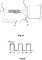
- the figure 1 is a schematic perspective view of a geared motor 100 comprising an electric motor 1 and a gear 2 and intended to drive for example a wiper system of a motor vehicle.
- the electric motor 1 comprises a stator 3 comprising stator plates 7 generally surrounded and protected by a carcass (not shown).
- the stator laminations 7 are configured to receive electromagnetic excitation coils 9.
- the electric motor 1 also comprises two bearings 11 (only one of the bearings 11 is visible on the figure 1 ) are arranged at both ends of a drive shaft 17.
- the bearings 11 make it possible to ensure the mechanical connection between the stator 3 and a rotor 15.
- Permanent magnets (not shown) are arranged on the drive shaft 17. mounted state of the electric motor 1, the permanent magnets are configured to come into contact with the electromagnetic excitation coils 9.
- the supply of the electromagnetic excitation coils 9 with appropriate control signals makes it possible to create a rotating field which causes rotating the rotor 15 via the permanent magnets.
- the electric motor 1 also comprises a control magnet 21 mounted on the drive shaft 17.
- the magnet 21 is multipolar and comprises at least one pair of magnetic poles.
- the control magnet 21 is intended to come into contact with at least one Hall effect sensor 23.
- the Hall effect sensor 23 is for example positioned on a printed circuit board 24 fixed on the stator 3
- the control magnet 21 may comprise several multipolar axial layers if a plurality of Hall effect sensors 23 are used. In the present case, three Hall effect sensors denoted 23a, 23b and 23c are respectively associated with three multipolar axial layers denoted 21a, 21b and 21c of the control magnet 21.
- the number of Hall effect sensors 23 is generally between 1 and 3.
- the Hall sensor (s) 23 is (are) configured to detect a magnetic pole of the control magnet 21 and by therefore an angular position of the control magnet 21.
- the electric motor 1 also comprises a control unit 25, represented on the figure 2 , and configured to receive the signals generated by the Hall effect sensor (s) 23 and to determine an angular position of the rotor 15 from the signals from said Hall effect sensor (s) 23.
- the control unit 25 may be implemented at the level of the printed circuit board 24.
- the control unit 25 is connected to the Hall sensor (s) 23 for example via a printed circuit or by a wired connection or by wireless communication means known to those skilled in the art.
- the control unit 25 is also configured to generate control signals from the angular position of the determined rotor. These control signals are used to supply the electromagnetic excitation coils 9 of the stator 3 in order to cause the rotor 15 to rotate.
- the control unit 25 comprises a clock 26 and is configured to estimate the position. angular rotor 15 between two signal state changes or signals from the Hall effect sensor (s) 23.
- the control unit 25 Preferably, only the signals from a single Hall effect sensor 23 are used by the control unit 25 to estimate the intermediate angular positions to avoid inserting an error in the estimate due to positioning tolerances of the others. Hall effect sensors 23.
- a single Hall effect sensor 23 will be used to estimate the intermediate angular positions, but it is also possible to use the signals from several Hall effect sensors. 23 without departing from the scope of the present invention. Tolerance errors can also be corrected by calibration.
- control magnet 21 comprises a pair of magnetic poles but it is also possible to use a control magnet 21 comprising a larger number of pairs of magnetic poles without leaving the of the present invention.
- the figure 3a represents an example of a control magnet 21 mounted on the shaft 17 of the rotor 15 comprising a pair of magnetic poles and the figure 3b represents the signal H from the Hall effect sensor 23 over time when the rotational speed of the rotor 15 supporting the control magnet 21 is constant.
- Two changes of state (the times of the changes of state being referenced 10, I1 ... I5) of the Hall effect sensor 23 correspond in this case to a rotation of 180 ° of the rotor 15.
- the control unit 25 can estimate the speed of rotation of the rotor 15 by, for example , at two previous state changes of the signal H from the Hall effect sensor 23.
- the angular position of the rotor 15 at each clock instant 26 can be estimated.
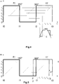
- the figure 4 represents an example of a graph representing the signal H from the Hall effect sensor 23 between the instants I0 and I2 of the state changes of the Hall effect sensor 23 of the figure 3a .
- time I2 it is possible from instants I0 and I1, for example, to estimate the instant I3 corresponding to the next change of state, for example by considering that the time interval I2-I3 is equal to I0-I1 time interval (assumption of a constant speed, which can often be assumed because of the inertia of the rotor 15).
- the time interval I2-I3 is equal to I0-I1 time interval (assumption of a constant speed, which can often be assumed because of the inertia of the rotor 15).
- I0-I1 time interval assumption of a constant speed, which can often be assumed because of the inertia of the rotor 15.
- these values can be generated by the control unit 25 from a predetermined mathematical equation.
- the greater the number of intermediate moments chosen the more the control signal obtained will be close to a sinusoidal signal.
- the figure 4 represents an example of a control signal C obtained by considering the intermediate moments i 21 to i 25 . Indeed, the signal obtained is quasi-sinusoidal or substantially sinusoidal since a single value is applied to the control signal between two intermediate moments, however, if the duration between two intermediate instants i 21 ... i 25 is sufficiently low, the control signal C obtained approaches a sinusoidal signal.
- the estimation of I3 and intermediate points i 21 ... i 25 can take into account not only the instants I0 and I1 but also the previous instants.
- a regression for example a polynomial or hyperbolic or other regression, may in particular be applied to determine a function corresponding to the evolution of the speed so as to determine the evolution of the speed between the instants I2 and I3.
- This determination is then repeated over time taking into account the instants of the new state changes, for example at each instant corresponding to a change of state of the signal H supplied by the Hall effect sensor 23.
- the information corresponding to the interval I1-I2 can be used (for example in combination with the interval I0-I1) to determine the instant I4 and the intermediate moments between I3 and I4.
- phase advance of the sinusoidal control signal C created.
- the figure 5 represents a diagram on which instants I'2 and I'3 are created by a time shift ⁇ T from instants I2 and I3, which also makes it possible to obtain intermediate instants i '21 ... i' 25 shifted and therefore to obtain a sinusoidal control signal C with a phase advance.
- This phase advance makes it possible to increase the torque supplied by the electric motor 1, the phase advance can be chosen according to the desired torque.
- the phase advance is for example applied when the rotation speed of the rotor 15 exceeds a predetermined threshold, here called the second predetermined threshold, and / or the desired torque exceeds a predetermined threshold.
- the application of a control signal C with a phase advance therefore depends on the torque to be supplied.
- control unit 25 can be configured to control the electric motor 1 by block control as long as the rotational speed is lower than a first predetermined threshold, for example 10% of the maximum rotational speed of the motor. rotor 15.
- the control unit 25 can use the signal or the signals coming from the Hall effect sensor (s).
- the electric motor 1 can for example comprise three Hall effect sensors. spaced from each other by 120 ° around a control magnet 21 comprising a pair of magnetic poles and providing the angular position of the rotor 15 every 60 ° to determine the switching times for the block drive or using three Hall effect sensors and a control magnet 21 comprising three multipolar axial layers arranged to allow detection of the angular position of the rotor 15 every 60 °
- a reduced number of Hall effect sensors 23, for example a single Hall effect sensor 23 can be used with a control magnet 21 comprising three pairs of poles in order to detect an angular position of the rotor every 60 ° and thus to determine switching times.
- Such block control allows a starting of the electric motor 1 with a large torque.
- Such a possibility is important in the case where the electric motor 1 is used in a geared motor of a wiper device for a motor vehicle, especially when the wiper blades strongly adhere to the windshield due to dirt or dirt. gel.
- the sinusoidal control as described above is applied.
- Such a sinusoidal (or quasi-sinusoidal) control makes it possible to obtain high torque at high speed and to obtain a smoother operation and thus to limit the noise of the electric motor 1.
- the large torque makes it possible to obtain a good operation of the wiper device even in case of dry windshield for example and the reduction of the noise emitted by the electric motor 1 improves the comfort of the passengers of the vehicle.
- the present invention also relates to a geared motor in which the electric motor is coupled to a reduction mechanism and a wiper system using the electric motor 1 described above, the output shaft of the reducing mechanism being for example connected to a control arm. windscreen wiper, possibly through a wheelhouse.
- the present invention also relates to a method for controlling a brushless direct current electric motor 1.
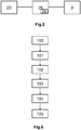
- the figure 6 represents the different steps of the process. Some steps may be optional and the order of steps may also differ, with some steps being simultaneous.
- the preliminary step 100 relates to the saving of a correspondence table between angular positions of the rotor 15 and associated control voltages for different commands of the electric motor 1.
- mathematical functions can be saved to enable the voltages of the motor to be calculated.
- Different mathematical functions can be associated with different commands of the motor 1 according to the desired rotational speed.
- the first step 101 consists of establishing a block command at the start of the electric motor 1 and up to a rotational speed of the electric motor 1 corresponding to a first predetermined threshold, for example 10% of the maximum rotational speed.
- the block control is established by determining the angular position of the rotor 15 (and hence the switching times) from the signal from at least one Hall effect sensor 23, generally three Hall effect sensors 23.
- the second step 102 concerns the estimation of the angular position of the rotor 15 at predetermined times between two instants corresponding to the changes of state of a Hall effect sensor 23.
- the signal coming from one of the Hall effect sensors 23 is selected and the angular position of the rotor 15 is estimated between the instants of change of state of the Hall effect sensor 23.
- This estimation is for example carried out as soon as the electric motor 1 has reached a rotation speed corresponding to a predefined value lower than the threshold defined in step 101, for example 8% of the maximum rotational speed.
- the estimation consists of estimating a rotational speed or an evolution of the rotational speed of the electric motor 1 from the instants of the previous changes of state and of applying the same speed of rotation or the same evolution of the speed of rotation. over the time interval until the moment of the next state change of the signal H from the Hall effect sensor 23. This determination can be repeated and updated with each new change of state of the Hall effect sensor 23.
- the estimation can also be made over a time interval corresponding to several changes in the state of the signal from the Hall effect sensor 23, for example over a time interval of two changes of state corresponding to a rotation of 360 Of the electric motor in the case of a control magnet comprising two magnetic poles.
- the rotational speed or evolution of the estimated rotational speed makes it possible to determine the angular position of the rotor 15 at each instant and in particular at selected predetermined moments.
- the third step 103 relates to the determination of a voltage value associated with each predetermined instant selected.
- the voltage values associated with the different positions of the rotor 15 to obtain a sinusoidal control signal C corresponding to the control of the electric motor 1 are saved in a memory of the control unit 25.
- these voltage values can be calculated by the control unit 25 from a mathematical function depending on the angular position of the rotor 15. Different mathematical functions can be associated with different engine control electrical 1 according to the desired speed of rotation for example.
- the fourth step 104 relates to the generation of a pseudo-sinusoidal control signal C from the voltage values determined in step 103.
- This control signal C generated is transmitted to the electromagnetic excitation coils 9 when the rotational speed the rotor 15 of the electric motor 1 is greater than the first predetermined threshold to produce a rotating field and drive the rotor 15 in rotation.
- the fifth step 105 is an optional step and concerns the generation of a substantially sinusoidal control signal C with a predetermined phase advance when the rotational speed of the rotor 15 exceeds a second predetermined threshold and / or when the torque to be supplied exceeds a predetermined threshold. predetermined value.
- the value of the phase advance can vary depending on the rotation speed and / or the torque to be provided so that the greater the rotation and / or the torque to be supplied, the greater the phase advance.
- the phase advance is obtained by inserting a time offset at the intermediate moments so that the voltage values determined in step 103 are applied with a lead time ⁇ T as previously described from the Figures 4 and 5 .
- such a control method makes it possible to obtain a high torque at startup and at high speeds of rotation if necessary while providing a quieter operation than with a block drive.
- such a method does not require expensive additional equipment such as an accurate encoder.
Abstract
La présente invention concerne un moteur électrique (1) à courant continu sans balais, notamment pour un système d'essuyage, comprenant : - un rotor (15) comprenant un aimant de commande, - un stator (3) présentant des bobines d'excitation électromagnétique (9) du rotor (15), - au moins un capteur à effet Hall (23) configuré pour détecter une position angulaire de l'aimant de commande (21), - une unité de commande (25) connectée audit capteur à effet Hall (25) et configurée pour déterminer au moins une position angulaire du rotor (15) par rapport au stator (3) à partir des signaux (H) du capteur à effet Hall (23) et pour générer des signaux de commande (C) pour alimenter les bobines d'excitation électromagnétique (9) du stator (3) en fonction de la position angulaire du rotor (15) déterminée, dans lequel l'unité de commande (25) comprend une horloge (26) et est configurée pour : - estimer la position angulaire du rotor (15) à une pluralité d'instants prédéterminés (i 21 ...i 25 ) compris entre deux changements d'état du capteur à effet Hall (23) à partir des instants (I0, I1) des précédents changements d'état, - déterminer des valeurs des tensions de commande associées aux positions angulaires du rotor (15) estimées pour les instants prédéterminés (i 21 ...i 25 ), lesdites valeurs de tension permettant de générer un signal de commande (C) sensiblement sinusoïdal, - générer un signal de commande (C) sensiblement sinusoïdal à partir des valeurs de tension déterminées. L'invention concerne également un moto-réducteur, un système d'essuyage et un procédé de commande du moteur électrique (1).The present invention relates to a brushless direct current electric motor (1), in particular for a wiper system, comprising: a rotor (15) comprising a control magnet, a stator (3) having electromagnetic excitation coils (9) of the rotor (15), at least one Hall effect sensor (23) configured to detect an angular position of the control magnet (21), a control unit (25) connected to said Hall effect sensor (25) and configured to determine at least one angular position of the rotor (15) relative to the stator (3) from the signals (H) of the Hall effect sensor (23) and for generating control signals (C) for supplying the electromagnetic excitation coils (9) of the stator (3) according to the angular position of the determined rotor (15), wherein the control unit (25) comprises a clock (26) and is configured to: - estimating the angular position of the rotor (15) at a plurality of predetermined times (i 21 ... i 25) between two state changes of the Hall effect sensor (23) from the instants (I0, I1) previous state changes, determining values of the control voltages associated with the angular positions of the rotor (15) estimated for the predetermined instants (i 21 ... i 25), said voltage values making it possible to generate a substantially sinusoidal control signal (C), generating a substantially sinusoidal control signal (C) from the determined voltage values. The invention also relates to a geared motor, a wiper system and a method of controlling the electric motor (1).
Description
La présente invention concerne un moteur électrique et notamment un moteur électrique d'un moto-réducteur pour systèmes d'essuyage de véhicule automobile.The present invention relates to an electric motor and in particular an electric motor of a geared motor for wiper systems of a motor vehicle.
Différents types de moteurs électriques peuvent être utilisés dans un moto-réducteur et notamment des moteurs électriques à courant continu sans balai qui présentent de nombreux avantages comme une grande durée de vie, un encombrement et une consommation réduits ainsi qu'un faible niveau sonore.Different types of electric motors can be used in a geared motor including brushless DC electric motors which have many advantages such as a long service life, reduced space and consumption and a low noise level.
Cependant, la commande des moteurs électriques à courant continu sans balai est plus complexe par rapport aux moteurs électriques à balais car pour permettre un bon fonctionnement, il est nécessaire de connaître précisément la position angulaire du rotor du moteur électrique à courant continu sans balai.However, the control of brushless DC electric motors is more complex compared to electric brush motors because to allow proper operation, it is necessary to know precisely the angular position of the rotor of the brushless DC electric motor.
En effet, de tels moteurs électriques comprennent des bobines d'excitation électromagnétique disposées au niveau du stator et alimentées alternativement via un onduleur pour permettre l'entraînement d'aimants permanents disposés sur le rotor.Indeed, such electric motors comprise electromagnetic excitation coils disposed at the stator and fed alternately via an inverter to allow the drive of permanent magnets arranged on the rotor.
On dénombre trois types de commande pour commuter les interrupteurs de l'onduleur et alimenter les bobines d'excitation électromagnétique :
- la commande en blocs en utilisant par exemple trois capteurs à effet Hall pour déterminer les positions angulaires du rotor aux instants des changements de commutation,
- la commande sans capteur ou « sensorless » où on applique une séquence prédéfinie au démarrage puis on détermine la position angulaire du rotor à partir des forces contre électromotrices mesurées lorsque la vitesse de rotation est suffisante, cependant cette commande ne permet pas des démarrages avec un couple élevé,
- la commande sinusoïdale qui permet d'augmenter la constante de couple et d'avoir une régulation plus en douceur qui permet de réduire le bruit, cependant cette commande nécessite un encodeur précis pour déterminer la position angulaire du rotor à chaque instant ce qui rend cette solution coûteuse.
- the block control using, for example, three Hall effect sensors for determining the angular positions of the rotor at the instant of the commutation changes,
- sensorless or "sensorless" control where a predefined sequence is applied at startup and then the rotor angular position is determined from the electromotive forces measured when the speed of rotation is sufficient, however this command does not allow starting with a torque Student,
- sinusoidal control that increases the torque constant and has a more smooth control that reduces noise, however this command requires a precise encoder to determine the angular position of the rotor at each moment what makes this solution expensive.
Dans le cas d'un moteur électrique destiné à être utilisé dans un moto-réducteur d'un système d'essuyage pour véhicule automobile, il convient d'avoir à la fois un moteur électrique permettant d'effectuer un démarrage avec un couple élevé (par exemple en cas d'essuie-glace collé par des saletés ou par le gel), un moteur électrique permettant d'avoir un couple élevé à haute vitesse de rotation (en cas de pare-brise sec), un moteur émettant un bruit faible et un coût de revient réduit.In the case of an electric motor for use in a gear motor of a wiper system for a motor vehicle, it is necessary to have both an electric motor for starting with a high torque ( for example in the case of wiper glued by dirt or frost), an electric motor allowing to have a high torque at high speed of rotation (in case of dry windshield), a motor emitting a weak noise and a reduced cost price.
La présente invention vise donc à fournir une solution pour permettre une commande efficace d'un moto-réducteur pour système d'essuyage pouvant fournir un couple élevé au démarrage et à haute vitesse tout en limitant le bruit de fonctionnement et le coût de revient.The present invention therefore aims to provide a solution to allow efficient control of a gear motor for a wiper system that can provide high torque at startup and at high speed while limiting the operating noise and cost.
A cet effet, la présente invention concerne un moteur électrique à courant continu sans balais, notamment pour un système d'essuyage, comprenant :
- un rotor comprenant un aimant de commande,
- un stator présentant des bobines d'excitation électromagnétique du rotor,
- au moins un capteur à effet Hall configuré pour détecter une position angulaire de l'aimant de commande,
- une unité de commande connectée audit capteur à effet Hall et configurée pour déterminer au moins une position angulaire du rotor par rapport au stator à partir des signaux du capteur à effet Hall et pour générer des signaux de commande pour alimenter les bobines d'excitation électromagnétique du stator en fonction de la position angulaire du rotor déterminée,
- estimer la position angulaire du rotor à une pluralité d'instants prédéterminés compris entre deux changements d'état du capteur à effet Hall à partir des instants des précédents changements d'état,
- déterminer des valeurs des tensions de commande associées aux positions angulaires du rotor estimées pour les instants prédéterminés, lesdites valeurs de tension permettant de générer un signal de commande sinusoïdal ou sensiblement sinusoïdal,
- générer un signal de commande sinusoïdal ou sensiblement sinusoïdal à partir des valeurs de tension déterminées.
- a rotor comprising a control magnet,
- a stator having electromagnetic excitation coils of the rotor,
- at least one Hall effect sensor configured to detect an angular position of the control magnet,
- a control unit connected to said Hall effect sensor and configured to determine at least one angular position of the rotor with respect to the stator from the Hall effect sensor signals and to generate control signals for supplying the electromagnetic excitation coils of the Hall sensor; stator according to the angular position of the determined rotor,
- estimating the angular position of the rotor at a plurality of predetermined times between two state changes of the Hall effect sensor from the instants of the previous state changes,
- determining values of the control voltages associated with the estimated rotor angular positions for the predetermined times, said voltage values for generating a sinusoidal or substantially sinusoidal control signal,
- generating a sinusoidal or substantially sinusoidal control signal from the determined voltage values.
L'estimation d'une position angulaire du rotor à des instants intermédiaires entre les signaux transmis par un capteur à effet Hall permet de recréer un encodeur précis pour un coût réduit et ainsi permettre de générer un signal de commande sinusoïdal sans avoir besoin d'utiliser un encodeur précis coûteux.The estimation of an angular position of the rotor at intermediate moments between the signals transmitted by a Hall effect sensor makes it possible to recreate an accurate encoder for a reduced cost and thus make it possible to generate a sinusoidal control signal without the need to use an expensive precise encoder.
La présente invention concerne également les aspects suivants qui peuvent être combinés entre eux pour fournir de nouveauThe present invention also relates to the following aspects which can be combined with one another to provide again
L'unité de commande est configurée pour générer un signal de commande en blocs à partir des changements d'état du, au moins un, capteur à effet Hall pour des vitesses de rotation inférieures à un premier seuil prédéterminé et pour générer un signal de commande sensiblement sinusoïdal pour des vitesses de rotation supérieures au premier seuil prédéterminé.The control unit is configured to generate a block control signal from the state changes of the at least one Hall effect sensor for rotational speeds below a first predetermined threshold and to generate a control signal. substantially sinusoidal for rotational speeds greater than the first predetermined threshold.
L'unité de commande est configurée pour générer un signal de commande sinusoïdal avec une avance de phase prédéterminée lorsque la vitesse de rotation dépasse un deuxième seuil prédéterminé.The control unit is configured to generate a sinusoidal control signal with a predetermined phase advance when the rotational speed exceeds a second predetermined threshold.
Le premier seuil prédéterminé correspond à une vitesse de rotation égale à 10% de la vitesse de rotation maximale.The first predetermined threshold corresponds to a rotation speed equal to 10% of the maximum rotational speed.
L'unité de commande est configurée pour générer un signal de commande sinusoïdal avec une avance de phase prédéterminée lorsque le couple à fournir est supérieur à un seuil prédéterminé.The control unit is configured to generate a sinusoidal control signal with a predetermined phase advance when the torque to be supplied is greater than a predetermined threshold.
Le moteur électrique comprend au moins deux capteurs à effet Hall et dans lequel l'unité de commande est configurée pour générer un signal de commande sensiblement sinusoïdal à partir du signal fourni par un seul des capteurs à effet Hall.The electric motor comprises at least two Hall effect sensors and wherein the control unit is configured to generate a substantially sinusoidal control signal from the signal provided by only one of the Hall effect sensors.
La présente invention concerne également un moto-réducteur, notamment pour système d'essuyage, comprenant un moteur électrique tel que décrit précédemment couplé à un réducteur.The present invention also relates to a geared motor, particularly for a wiper system, comprising an electric motor as described previously coupled to a gearbox.
La Présente invention concerne également un système d'essuyage, notamment pour véhicule automobile, comprenant un moto-réducteur tel que décrit précédemment.The present invention also relates to a wiper system, especially for a motor vehicle, comprising a geared motor as described above.
La présente invention concerne également un procédé de commande d'un moteur électrique à courant continu sans balais, notamment pour un système d'essuyage, comprenant :
- un rotor comprenant un aimant de commande,
- un stator présentant des bobines d'excitation électromagnétique du rotor,
- au moins un capteur à effet Hall configuré pour détecter une position angulaire de l'aimant de commande,
- une unité de commande connectée audit capteur à effet Hall et configurée pour déterminer une position angulaire du rotor par rapport au stator à partir des signaux du capteur à effet Hall et pour générer des signaux de commande pour alimenter les bobines d'excitation électromagnétique du stator en fonction de la position angulaire du rotor déterminée,
- on estime la position angulaire du rotor à une pluralité d'instants prédéterminés compris entre deux changements d'état du capteur à effet Hall à partir des instants des précédents changements d'état,
- on détermine les valeurs des tensions de commande associées aux positions angulaires du rotor estimées pour les instants prédéterminés, lesdites valeurs de tension permettant de générer un signal de commande sensiblement sinusoïdal,
- on génère un signal de commande sensiblement sinusoïdal à partir des valeurs de tension déterminées.
- a rotor comprising a control magnet,
- a stator having electromagnetic excitation coils of the rotor,
- at least one Hall effect sensor configured to detect an angular position of the control magnet,
- a control unit connected to said Hall effect sensor and configured to determine an angular position of the rotor relative to the stator from the Hall effect sensor signals and to generate control signals for supplying the electromagnetic excitation coils of the stator to depending on the angular position of the determined rotor,
- the angular position of the rotor is estimated at a plurality of predetermined times between two state changes of the Hall sensor from the instants of the previous state changes,
- the values of the control voltages associated with the estimated rotor angular positions are determined for the predetermined instants, said voltage values making it possible to generate a substantially sinusoidal control signal,
- a substantially sinusoidal control signal is generated from the determined voltage values.
Le procédé comprend également les aspects suivants :
- L'étape d'estimation de la position angulaire du rotor à une pluralité d'instants prédéterminés compris entre deux changements d'état du capteur à effet Hall est réalisée à partir des instants des deux précédents changements d'état du capteur à effet Hall en supposant que la vitesse de rotation est constante.
- The step of estimating the angular position of the rotor at a plurality of predetermined times between two state changes of the Hall effect sensor is performed from the instants of the two previous state changes of the Hall effect sensor. assuming that the speed of rotation is constant.
L'étape d'estimation de la position angulaire du rotor à une pluralité d'instants prédéterminés compris entre deux changements d'état du capteur à effet Hall est réalisée à partir des instants d'au moins trois précédents changements d'état du capteur à effet Hall pour prendre en compte une évolution de la vitesse de rotation du rotor.The step of estimating the angular position of the rotor at a plurality of predetermined times between two changes of state of the Hall effect sensor is performed from the instants of at least three previous changes of state of the sensor to Hall effect to take into account an evolution of the rotational speed of the rotor.
Le procédé comprend une étape préliminaire de sauvegarde d'une table de correspondance entre des positions angulaires du rotor et des tensions de commande associées pour obtenir un signal de commande sensiblement sinusoïdal et dans lequel l'étape de détermination des valeurs des tensions de commande associées aux positions angulaires du rotor comprend la recherche de ces valeurs dans la table de correspondance sauvegardée.The method comprises a preliminary step of saving a correspondence table between angular positions of the rotor and associated control voltages to obtain a substantially sinusoidal control signal and wherein the step of determining the values of the control voltages associated with the Rotor angular positions include finding these values in the saved correspondence table.
Le procédé comprend une étape dans laquelle on génère un signal de commande sensiblement sinusoïdal avec une avance de phase prédéterminée lorsque la vitesse de rotation du rotor dépasse un deuxième seuil prédéterminé.The method comprises a step in which a substantially sinusoidal control signal is generated with a predetermined phase advance when the rotational speed of the rotor exceeds a second predetermined threshold.
Le procédé comprend une étape dans laquelle on génère un signal de commande sensiblement sinusoïdal avec une avance de phase prédéterminée lorsque le couple à fournir est supérieur à un seuil prédéterminé.The method comprises a step in which a substantially sinusoidal control signal is generated with a predetermined phase advance when the torque to be supplied is greater than a predetermined threshold.
Le signal de commande avec une avance de phase est obtenu en introduisant un décalage temporel pour l'application des tensions de commande déterminées.The control signal with a phase advance is obtained by introducing a time shift for the application of the determined control voltages.
Pour des vitesses de rotation inférieures à un premier seuil prédéterminé, on génère un signal de commande en blocs à partir des changements d'état d'au moins un capteur à effet Hall et pour des vitesses de rotation supérieures au premier seuil prédéterminé, on génère un signal de commande sensiblement sinusoïdal à partir des signaux issus d'un seul capteur à effet Hall selon le procédé de commande décrit précédemment.For rotation speeds lower than a first predetermined threshold, a block control signal is generated from the state changes of at least one Hall effect sensor and for rotational speeds higher than the first predetermined threshold, it generates a substantially sinusoidal control signal from the signals from a single Hall effect sensor according to the control method described above.
D'autres caractéristiques et avantages de l'invention ressortiront de la description suivante, donnée à titre d'exemple et sans caractère limitatif, en regard des dessins annexés sur lesquels :
- la
figure 1 représente un schéma d'une vue en perspective d'un moto-réducteur électrique à courant continu sans balai, - La
figure 2 représente un schéma d'une unité de commande reliée à un capteur à effet Hall et à des bobines d'excitation électromagnétique ; - les
figures 3a et 3b représentent respectivement une vue en perspective d'une aimant de commande associé à un capteur a effet Hall et du signal fourni par le capteur à effet Hall lors d'une rotation de l'aimant de commande, - la
figure 4 représente un diagramme du signal fourni par un capteur à effet Hall en fonction du temps lors d'une rotation de l'aimant de commande, le signal estimé pour le prochain cycle et le signal de commande obtenu pour le prochain cycle, - la
figures 5 représente un diagramme du signal fourni par un capteur à effet Hall en fonction du temps lors d'une rotation de l'aimant de commande et le signal estimé pour le prochain cycle décalé temporellement.
- the
figure 1 represents a diagram of a perspective view of a brushless direct current electric gear motor, - The
figure 2 represents a diagram of a control unit connected to a Hall effect sensor and to electromagnetic excitation coils; - the
Figures 3a and 3b respectively show a perspective view of a control magnet associated with a Hall effect sensor and the signal provided by the Hall effect sensor during a rotation of the control magnet, - the
figure 4 represents a diagram of the signal provided by a Hall effect sensor as a function of time during a rotation of the control magnet, the estimated signal for the next cycle and the control signal obtained for the next cycle, - the
figures 5 represents a diagram of the signal provided by a Hall effect sensor as a function of time during a rotation of the control magnet and the estimated signal for the next time-shifted cycle.
Sur toutes les figures, les éléments identiques portent les mêmes numéros de référence.In all the figures, the identical elements bear the same reference numbers.
Les réalisations suivantes sont des exemples. Bien que la description se réfère à un ou plusieurs modes de réalisation, ceci ne signifie pas nécessairement que chaque référence concerne le même mode de réalisation ou que les caractéristiques s'appliquent seulement à un seul mode de réalisation. De simples caractéristiques de différents modes de réalisation peuvent également être combinées ou interchangées pour fournir d'autres réalisations.The following achievements are examples. Although the description refers to one or more embodiments, this does not necessarily mean that each reference relates to the same embodiment or that the features apply only to a single embodiment. Simple features of different embodiments may also be combined or interchanged to provide other embodiments.
La
Le moteur électrique 1 comprend un stator 3 comprenant des tôles statoriques 7 généralement entourées et protégées par une carcasse (non représentée). Les tôles statoriques 7 sont configurées pour recevoir des bobines d'excitation électromagnétique 9. Le moteur électrique 1 comprend également deux paliers 11 (seul l'un des paliers 11 est visible sur la
De plus, afin de pouvoir établir des signaux de commande adaptés, il est nécessaire de connaître la position angulaire du rotor 15. Pour cela, le moteur électrique 1 comprend également un aimant de commande 21 monté sur l'arbre moteur 17. L'aimant de commande 21 est multipolaire et comprend au moins une paire de pôles magnétiques. A l'état monté, l'aimant de commande 21 est destiné à venir en regard avec au moins un capteur à effet Hall 23. Le capteur à effet Hall 23 est par exemple positionné sur une carte à circuit imprimé 24 fixée sur le stator 3. L'aimant de commande 21 peut comprendre plusieurs couches axiales multipolaires si plusieurs capteurs à effet Hall 23 sont utilisés. Dans le cas présent, trois capteurs à effet Hall notés 23a, 23b et 23c sont associés respectivement à trois couches axiales multipolaires notées 21a, 21b et 21c de l'aimant de commande 21.In addition, in order to be able to establish appropriate control signals, it is necessary to know the angular position of the
Le nombre de capteurs à effet Hall 23 est généralement compris entre 1 et 3. Le(s) capteur(s) à effet Hall 23 est (sont) configuré(s) pour détecter un pôle magnétique de l'aimant de commande 21 et par conséquent une position angulaire de l'aimant de commande 21.The number of
Le moteur électrique 1 comprend également une unité de commande 25, représentée sur la
De préférence, seuls les signaux issus d'un seul capteur à effet Hall 23 sont utilisés par l'unité de commande 25 pour estimer les positions angulaires intermédiaires pour éviter d'insérer une erreur dans l'estimation due à des tolérances de positionnement des autres capteurs à effet Hall 23. Ainsi, dans la suite de la description, un seul capteur à effet Hall 23 sera utilisé pour réaliser l'estimation des positions angulaires intermédiaires mais il est également possible d'utiliser les signaux issus de plusieurs capteurs à effet Hall 23 sans sortir du cadre de la présente invention. Les erreurs de tolérance peuvent aussi être corrigées par un calibrage.Preferably, only the signals from a single
De plus, on se limitera à la description du cas où l'aimant de commande 21 comprend une paire de pôles magnétiques mais il est également possible d'utiliser un aimant de commande 21 comprenant un nombre de paire de pôles magnétiques plus important sans sortir du cadre de la présente invention.In addition, it will be limited to the description of the case where the
La
Pour réaliser l'estimation de la position angulaire du rotor 15 entre deux changements d'état du signal H issu d'un capteur à effet Hall 23, l'unité de commande 25 peut estimer la vitesse de rotation du rotor 15 grâce, par exemple, à deux changements d'état précédents du signal H issu du capteur à effet Hall 23. Ainsi, à partir de cette vitesse de rotation estimée, la position angulaire du rotor 15 à chaque instant d'horloge 26 peut être estimée.To realize the estimation of the angular position of the
La
De plus, afin d'améliorer la précision de l'estimation de la position angulaire du rotor 15 aux instants intermédiaires i21...i25, il est également possible de tenir compte de plusieurs instants I0, Il... précédents pour prendre en compte une évolution de la vitesse de rotation sur plusieurs intervalles de temps entre deux changements d'état. Par exemple dans le cas de la
De plus, en appliquant un décalage temporel sur les instants I1, 12...et les instants intermédiaire i21...i25, il est possible de créer une avance de phase du signal de commande C sinusoïdal créé. La
Par ailleurs, l'estimation des positions angulaires du rotor 15 aux instants intermédiaires n'étant pas possible au démarrage, puisqu'il n'y a pas de signal de changement d'état antérieur pour estimer la vitesse. Ainsi, au démarrage, l'unité de commande 25 peut être configurée pour commander le moteur électrique 1 par une commande en blocs tant que la vitesse de rotation est inférieure à un premier seuil prédéterminé, par exemple 10 % de la vitesse de rotation maximale du rotor 15.Moreover, the estimation of the angular positions of the
Pour effectuer cette commande en blocs, l'unité de commande 25 peut utiliser le signal ou les signaux issu(s) du ou des capteur(s) à effet Hall 23. Le moteur électrique 1 peut par exemple comprendre trois capteurs à effet Hall 23 espacés les uns des autres de 120° autour d'un aimant de commande 21 comprenant une paire de pôles magnétiques et fournissant la position angulaire du rotor 15 tous les 60° afin de déterminer les instants de commutation pour la commande en blocs ou en utilisant trois capteurs à effet Hall et un aimant de commande 21 comprenant trois couches axiales multipolaires disposées de manière à permettre un détection de la position angulaire du rotor 15 tous les 60°To carry out this command in blocks, the
Alternativement, un nombre réduit de capteurs à effet Hall 23 par exemple un seul capteur à effet Hall 23 peut être utilisé avec un aimant de commande 21 comprenant trois paires de pôles afin de détecter une position angulaire du rotor tous les 60° et déterminer ainsi les instants de commutation.Alternatively, a reduced number of
Une telle commande par blocs permet un démarrage du moteur électrique 1 avec un couple important. Une telle possibilité est importante dans le cas où le moteur électrique 1 est utilisé dans un moto-réducteur d'un dispositif d'essuyage pour véhicule automobile, notamment lorsque les balais d'essuyage adhèrent fortement au pare-brise du fait de saletés ou du gel.Such block control allows a starting of the
Puis, lorsque la vitesse de rotation du rotor 15 du moteur électrique 1 dépasse le premier seuil prédéterminé, la commande sinusoïdale tel que décrite précédemment est appliquée. Une telle commande sinusoïdale (ou quasi-sinusoïdale) permet d'obtenir un couple important à haut régime et d'obtenir un fonctionnement plus doux et donc de limiter le bruit du moteur électrique 1. Le couple important permet d'obtenir un bon fonctionnement du dispositif d'essuyage même en cas de pare-brise sec par exemple et la réduction du bruit émis par le moteur électrique 1 permet d'améliorer le confort des passagers du véhicule.Then, when the rotational speed of the
La présente invention concerne également un moto-réducteur dans lequel le moteur électrique est couplé à un mécanisme réducteur et un système d'essuyage utilisant le moteur électrique 1 décrit précédemment, l'arbre de sortie du mécanisme réducteur étant par exemple relié à un bras d'essuie-glace, éventuellement par le biais d'une timonerie.The present invention also relates to a geared motor in which the electric motor is coupled to a reduction mechanism and a wiper system using the
La présente invention concerne également un procédé de commande d'un moteur électrique 1 à courant continu sans balai. La
L'étape préliminaire 100 concerne la sauvegarde d'une table de correspondance entre des positions angulaires du rotor 15 et des tensions de commande associées pour différentes commandes du moteur électrique 1. Alternativement, des fonctions mathématiques peuvent être sauvegardées pour permettre de calculer les tensions de commande associées aux différentes positions du rotor 15. Différentes fonctions mathématiques peuvent être associées à différentes commandes du moteur 1 en fonction de la vitesse de rotation désirée.The
La première étape 101 consiste à établir une commande en blocs au démarrage du moteur électrique 1 et jusqu'à une vitesse de rotation du moteur électrique 1 correspondant à un premier seuil prédéterminé, par exemple 10 % de la vitesse de rotation maximale. La commande par blocs est établie en déterminant la position angulaire du rotor 15 (et donc les instants de commutation) à partir du signal issu d'au moins un capteur à effet Hall 23, généralement trois capteurs à effet Hall 23.The
La deuxième étape 102 concerne l'estimation de la position angulaire du rotor 15 à des instants prédéterminés entre deux instants correspondant aux changements d'état d'un capteur à effet Hall 23. Ainsi, dans le cas d'un moteur électrique 1 comprenant plusieurs capteurs à effet Hall 23, on sélectionne le signal issu d'un des capteurs à effet Hall 23 et on estime la position angulaire du rotor 15 entre les instants de changement d'état du capteur à effet Hall 23. Cette estimation est par exemple réalisée dès que le moteur électrique 1 a atteint une vitesse de rotation correspondant à une valeur prédéfinie inférieure au seuil défini dans l'étape 101, par exemple 8 % de la vitesse de rotation maximale. L'estimation consiste à estimer une vitesse de rotation ou une évolution de la vitesse de rotation du moteur électrique 1 à partir des instants des changements d'état précédents et d'appliquer la même vitesse de rotation ou la même évolution de la vitesse de rotation sur l'intervalle de temps jusqu'à l'instant du changement d'état suivant du signal H issu du capteur à effet Hall 23. Cette détermination pouvant être réitérée et mise à jour à chaque nouveau changement d'état du capteur à effet Hall 23. L'estimation peut aussi être faite sur un intervalle de temps correspondant à plusieurs changements d'état du signal issu du capteur à effet Hall 23, par exemple sur un intervalle de temps de deux changements d'état correspondant à une rotation de 360° du moteur électrique dans le cas d'un aimant de commande comprenant deux pôles magnétiques. Ainsi, la vitesse de rotation ou évolution de la vitesse de rotation estimée permet de déterminer la position angulaire du rotor 15 à chaque instant et notamment à des instants prédéterminés sélectionnés.The
La troisième étape 103 concerne la détermination d'une valeur de tension associée à chaque instant prédéterminé sélectionné. Pour cela, les valeurs de tensions associées aux différentes positions du rotor 15 pour obtenir un signal de commande C sinusoïdal correspondant à la commande du moteur électrique 1 sont sauvegardées dans une mémoire de l'unité de commande 25. Alternativement, ces valeurs de tensions peuvent être calculées par l'unité de commande 25 à partir d'une fonction mathématique dépendant de la position angulaire du rotor 15. Différentes fonctions mathématiques peuvent être associées à différentes commande du moteur électrique 1 en fonction de la vitesse de rotation désirée par exemple.The
La quatrième étape 104 concerne la génération d'un signal de commande C pseudo-sinusoïdal à partir des valeurs de tension déterminés à l'étape 103. Ce signal de commande C généré est transmis aux bobines d'excitation électromagnétique 9 lorsque la vitesse de rotation du rotor 15 du moteur électrique 1 est supérieure au premier seuil prédéterminé pour produire un champ tournant et entraîner le rotor 15 en rotation.The
La cinquième étape 105 est une étape facultative et concerne la génération d'un signal de commande C sensiblement sinusoïdal avec une avance de phase prédéterminée lorsque la vitesse de rotation du rotor 15 dépasse un deuxième seuil prédéterminé et/ou lorsque le couple à fournir dépasse une valeur prédéterminée. La valeur de l'avance de phase peut varier en fonction de la vitesse de rotation et/ou du couple à fournir de sorte que plus la rotation et/ou le couple à fournir sont importants et plus l'avance de phase est importante. L'avance de phase est obtenue en insérant un décalage temporel au niveau des instants intermédiaires de sorte que les valeurs de tension déterminées à l'étape 103 sont appliquées avec un temps d'avance ΔT comme décrit précédemment à partir des
Ainsi, un tel procédé de commande permet d'obtenir un couple élevé au démarrage et à hautes vitesses de rotation si nécessaire tout en procurant un fonctionnement moins bruyant qu'avec une commande en blocs. De plus, un tel procédé ne nécessite pas d'équipements supplémentaires coûteux tel qu'un encodeur précis.Thus, such a control method makes it possible to obtain a high torque at startup and at high speeds of rotation if necessary while providing a quieter operation than with a block drive. In addition, such a method does not require expensive additional equipment such as an accurate encoder.
Claims (16)
Applications Claiming Priority (1)
| Application Number | Priority Date | Filing Date | Title |
|---|---|---|---|
| FR1752535A FR3064427B1 (en) | 2017-03-27 | 2017-03-27 | ELECTRIC MOTOR, REDUCER MOTOR, WIPER SYSTEM AND ASSOCIATED CONTROL PROCEDURE |
Publications (1)
| Publication Number | Publication Date |
|---|---|
| EP3382886A1 true EP3382886A1 (en) | 2018-10-03 |
Family
ID=59153054
Family Applications (1)
| Application Number | Title | Priority Date | Filing Date |
|---|---|---|---|
| EP18163218.3A Withdrawn EP3382886A1 (en) | 2017-03-27 | 2018-03-22 | Electric motor, gear motor, wiping system and associated control method |
Country Status (5)
| Country | Link |
|---|---|
| US (1) | US10432114B2 (en) |
| EP (1) | EP3382886A1 (en) |
| JP (1) | JP2018191497A (en) |
| CN (1) | CN108667254B (en) |
| FR (1) | FR3064427B1 (en) |
Families Citing this family (3)
| Publication number | Priority date | Publication date | Assignee | Title |
|---|---|---|---|---|
| FR3066970B1 (en) * | 2017-06-02 | 2021-01-01 | Valeo Systemes Dessuyage | MOTOR-REDUCER FOR MOTOR VEHICLE WIPING SYSTEM |
| WO2020224645A1 (en) * | 2019-05-08 | 2020-11-12 | 上海禹点电子科技有限公司 | Speed regulation control system for windshield wiper |
| FR3121984B1 (en) * | 2021-04-14 | 2023-04-14 | Vitesco Technologies | Method for adapting to the tolerances of a system comprising a position sensor and a rotating target |
Citations (1)
| Publication number | Priority date | Publication date | Assignee | Title |
|---|---|---|---|---|
| EP2840700A1 (en) * | 2012-04-16 | 2015-02-25 | Mitsuba Corporation | Brushless motor and wiper device |
Family Cites Families (8)
| Publication number | Priority date | Publication date | Assignee | Title |
|---|---|---|---|---|
| WO1995024071A1 (en) * | 1994-03-03 | 1995-09-08 | Iomega Corporation | Servo motor controller using position interpolation |
| US6239564B1 (en) * | 1998-10-06 | 2001-05-29 | H.R. Textron, Inc. | State advance controller commutation loop for brushless D.C. motors |
| US7005810B2 (en) * | 2003-02-21 | 2006-02-28 | Matsushita Electric Industrial Co., Ltd. | Motor driving apparatus |
| JP2011010401A (en) * | 2009-06-24 | 2011-01-13 | Jtekt Corp | Motor controller and motor-driven power steering device |
| KR101240140B1 (en) * | 2009-09-01 | 2013-03-07 | 주식회사 만도 | Method and Apparatus for Recognizing Rotor Position, and Electric Power Steering System Using the Same |
| JP5824660B2 (en) * | 2010-07-12 | 2015-11-25 | パナソニックIpマネジメント株式会社 | Phase shift detection device, motor drive device, brushless motor, and phase shift detection method |
| KR101927693B1 (en) * | 2012-01-26 | 2018-12-12 | 삼성전자 주식회사 | Sensorless controlling apparatus and method for motor |
| JP2016111920A (en) * | 2014-11-26 | 2016-06-20 | 株式会社リコー | Permanent magnet type motor, position estimation device, and motor drive controller |
-
2017
- 2017-03-27 FR FR1752535A patent/FR3064427B1/en active Active
-
2018
- 2018-03-22 EP EP18163218.3A patent/EP3382886A1/en not_active Withdrawn
- 2018-03-26 JP JP2018058353A patent/JP2018191497A/en active Pending
- 2018-03-27 US US15/936,562 patent/US10432114B2/en active Active
- 2018-03-27 CN CN201810257293.XA patent/CN108667254B/en active Active
Patent Citations (1)
| Publication number | Priority date | Publication date | Assignee | Title |
|---|---|---|---|---|
| EP2840700A1 (en) * | 2012-04-16 | 2015-02-25 | Mitsuba Corporation | Brushless motor and wiper device |
Non-Patent Citations (3)
| Title |
|---|
| KIM JONGHWA ET AL: "Position Estimation Using Linear Hall Sensors for Permanent Magnet Linear Motor Systems", IEEE TRANSACTIONS ON INDUSTRIAL ELECTRONICS, IEEE SERVICE CENTER, PISCATAWAY, NJ, USA, vol. 63, no. 12, 1 December 2016 (2016-12-01), pages 7644 - 7652, XP011633598, ISSN: 0278-0046, [retrieved on 20161108], DOI: 10.1109/TIE.2016.2591899 * |
| RUIQING MA ET AL: "A novel sinusoidal current driving method for BLDCM based on SVPWM", ELECTRICAL MACHINES AND SYSTEMS (ICEMS), 2010 INTERNATIONAL CONFERENCE ON, IEEE, PISCATAWAY, NJ, USA, 10 October 2010 (2010-10-10), pages 732 - 735, XP031832835, ISBN: 978-1-4244-7720-3 * |
| SREEJITH KUMAR N ET AL: "Quasi sinusoid commutation for BLDC motor A simplified approach on 16 bit microcontroller platform", POWER ELECTRONICS, DRIVES AND ENERGY SYSTEMS (PEDES), 2012 IEEE INTERNATIONAL CONFERENCE ON, IEEE, 16 December 2012 (2012-12-16), pages 1 - 9, XP032346363, ISBN: 978-1-4673-4506-4, DOI: 10.1109/PEDES.2012.6484306 * |
Also Published As
| Publication number | Publication date |
|---|---|
| FR3064427B1 (en) | 2021-10-22 |
| CN108667254B (en) | 2020-09-01 |
| US10432114B2 (en) | 2019-10-01 |
| JP2018191497A (en) | 2018-11-29 |
| FR3064427A1 (en) | 2018-09-28 |
| US20180294750A1 (en) | 2018-10-11 |
| CN108667254A (en) | 2018-10-16 |
Similar Documents
| Publication | Publication Date | Title |
|---|---|---|
| EP1881594B1 (en) | Method of adjusting parameters of a synchronous motor and variable speed drive using such a method | |
| EP3516764B1 (en) | Gear motor, associated wiper system and associated control method | |
| EP3382886A1 (en) | Electric motor, gear motor, wiping system and associated control method | |
| EP3542450A1 (en) | Gear motor, associated wiper system and associated control method | |
| FR2894735A1 (en) | SYNCHRONOUS MOTOR GENERATOR WITH FIELD WINDING | |
| FR3062762A1 (en) | METHOD OF ESTIMATING THE ANGULAR POSITION OF A ROTOR OF AN ELECTRIC DRIVE SYSTEM | |
| EP1285490B1 (en) | Method for determining the position of a rotor of an electromagnetic motor with no commutator and device therefor | |
| WO2020001904A1 (en) | Brushless direct current electric motor and method for controlling same | |
| EP3382887A1 (en) | Method for starting a synchronous machine, associated control device, synchronous machine and compressor | |
| FR2908246A1 (en) | Direct current electric motor for driving e.g. window regulator, of motor vehicle, has two set of coils integrated to shaft and supplied by current to induce shaft rotation, where one set has impedance value different from that of other set | |
| EP3394978B1 (en) | Pseudo-sinusoidal control method for controlling a synchronous electric motor | |
| WO2020002553A1 (en) | Brushless direct current electric motor and associated control method | |
| FR2864722A1 (en) | DC commutator motor drive force determining process for motor vehicle, involves obtaining frequency spectrums characterizing rotational position of DC commutator motor during predetermined time period | |
| EP3815239A1 (en) | Brushless direct-current electric motor and associated control method | |
| WO2017129902A1 (en) | Spectral spread for electric motor | |
| FR3128598A1 (en) | Method for automatic setting of an angular position sensor | |
| FR3049410A1 (en) | STARTING METHOD FOR SYNCHRONOUS MACHINE, CONTROL DEVICE, SYNCHRONOUS MACHINE, AND COMPRESSOR THEREFOR. | |
| FR3121984A1 (en) | Method for adapting to the tolerances of a system comprising a position sensor and a rotating target | |
| FR3131993A1 (en) | Device and method for controlling a synchronous machine and estimating the rotor position, starting at a predetermined low speed | |
| FR2843248A1 (en) | Brushless polyphase electrical motor synchronised control system having detection determining rotor positions and synchronisation logic determining phase sequence/applying identically through power electronics. | |
| EP3235117A1 (en) | Method and device for evaluating operating parameters as well as process and system for controlling a synchronous machine | |
| FR2517088A1 (en) | Electric speed controller for slowly rotating alternator - uses phase sensitive rectifier to generate voltage controlling frequency of energy converter driving motor | |
| FR2986289A1 (en) | Active magnetic bearing e.g. radial-type active magnetic bearing, with self-position detection for electrical motor, has control device including position estimating unit to estimate position of ferromagnetic body forming rotor |
Legal Events
| Date | Code | Title | Description |
|---|---|---|---|
| PUAI | Public reference made under article 153(3) epc to a published international application that has entered the european phase |
Free format text: ORIGINAL CODE: 0009012 |
|
| STAA | Information on the status of an ep patent application or granted ep patent |
Free format text: STATUS: REQUEST FOR EXAMINATION WAS MADE |
|
| 17P | Request for examination filed |
Effective date: 20180322 |
|
| AK | Designated contracting states |
Kind code of ref document: A1 Designated state(s): AL AT BE BG CH CY CZ DE DK EE ES FI FR GB GR HR HU IE IS IT LI LT LU LV MC MK MT NL NO PL PT RO RS SE SI SK SM TR |
|
| AX | Request for extension of the european patent |
Extension state: BA ME |
|
| STAA | Information on the status of an ep patent application or granted ep patent |
Free format text: STATUS: EXAMINATION IS IN PROGRESS |
|
| 17Q | First examination report despatched |
Effective date: 20200218 |
|
| STAA | Information on the status of an ep patent application or granted ep patent |
Free format text: STATUS: THE APPLICATION IS DEEMED TO BE WITHDRAWN |
|
| 18D | Application deemed to be withdrawn |
Effective date: 20200829 |