EP3382886A1 - Elektromotor, getriebemotor, wischsystem und entsprechendes steuerverfahren - Google Patents
Elektromotor, getriebemotor, wischsystem und entsprechendes steuerverfahren Download PDFInfo
- Publication number
- EP3382886A1 EP3382886A1 EP18163218.3A EP18163218A EP3382886A1 EP 3382886 A1 EP3382886 A1 EP 3382886A1 EP 18163218 A EP18163218 A EP 18163218A EP 3382886 A1 EP3382886 A1 EP 3382886A1
- Authority
- EP
- European Patent Office
- Prior art keywords
- rotor
- hall effect
- control
- effect sensor
- control signal
- Prior art date
- Legal status (The legal status is an assumption and is not a legal conclusion. Google has not performed a legal analysis and makes no representation as to the accuracy of the status listed.)
- Withdrawn
Links
Images

Classifications
-
- H—ELECTRICITY
- H02—GENERATION; CONVERSION OR DISTRIBUTION OF ELECTRIC POWER
- H02K—DYNAMO-ELECTRIC MACHINES
- H02K29/00—Motors or generators having non-mechanical commutating devices, e.g. discharge tubes or semiconductor devices
- H02K29/06—Motors or generators having non-mechanical commutating devices, e.g. discharge tubes or semiconductor devices with position sensing devices
- H02K29/08—Motors or generators having non-mechanical commutating devices, e.g. discharge tubes or semiconductor devices with position sensing devices using magnetic effect devices, e.g. Hall-plates, magneto-resistors
-
- H—ELECTRICITY
- H02—GENERATION; CONVERSION OR DISTRIBUTION OF ELECTRIC POWER
- H02P—CONTROL OR REGULATION OF ELECTRIC MOTORS, ELECTRIC GENERATORS OR DYNAMO-ELECTRIC CONVERTERS; CONTROLLING TRANSFORMERS, REACTORS OR CHOKE COILS
- H02P6/00—Arrangements for controlling synchronous motors or other dynamo-electric motors using electronic commutation dependent on the rotor position; Electronic commutators therefor
- H02P6/08—Arrangements for controlling the speed or torque of a single motor
-
- B—PERFORMING OPERATIONS; TRANSPORTING
- B60—VEHICLES IN GENERAL
- B60S—SERVICING, CLEANING, REPAIRING, SUPPORTING, LIFTING, OR MANOEUVRING OF VEHICLES, NOT OTHERWISE PROVIDED FOR
- B60S1/00—Cleaning of vehicles
- B60S1/02—Cleaning windscreens, windows or optical devices
- B60S1/04—Wipers or the like, e.g. scrapers
- B60S1/06—Wipers or the like, e.g. scrapers characterised by the drive
- B60S1/08—Wipers or the like, e.g. scrapers characterised by the drive electrically driven
-
- B—PERFORMING OPERATIONS; TRANSPORTING
- B60—VEHICLES IN GENERAL
- B60S—SERVICING, CLEANING, REPAIRING, SUPPORTING, LIFTING, OR MANOEUVRING OF VEHICLES, NOT OTHERWISE PROVIDED FOR
- B60S1/00—Cleaning of vehicles
- B60S1/02—Cleaning windscreens, windows or optical devices
- B60S1/04—Wipers or the like, e.g. scrapers
- B60S1/06—Wipers or the like, e.g. scrapers characterised by the drive
- B60S1/16—Means for transmitting drive
- B60S1/166—Means for transmitting drive characterised by the combination of a motor-reduction unit and a mechanism for converting rotary into oscillatory movement
-
- B—PERFORMING OPERATIONS; TRANSPORTING
- B60—VEHICLES IN GENERAL
- B60S—SERVICING, CLEANING, REPAIRING, SUPPORTING, LIFTING, OR MANOEUVRING OF VEHICLES, NOT OTHERWISE PROVIDED FOR
- B60S1/00—Cleaning of vehicles
- B60S1/02—Cleaning windscreens, windows or optical devices
- B60S1/04—Wipers or the like, e.g. scrapers
- B60S1/06—Wipers or the like, e.g. scrapers characterised by the drive
- B60S1/16—Means for transmitting drive
- B60S1/18—Means for transmitting drive mechanically
- B60S1/26—Means for transmitting drive mechanically by toothed gearing
-
- H—ELECTRICITY
- H02—GENERATION; CONVERSION OR DISTRIBUTION OF ELECTRIC POWER
- H02K—DYNAMO-ELECTRIC MACHINES
- H02K11/00—Structural association of dynamo-electric machines with electric components or with devices for shielding, monitoring or protection
- H02K11/20—Structural association of dynamo-electric machines with electric components or with devices for shielding, monitoring or protection for measuring, monitoring, testing, protecting or switching
- H02K11/21—Devices for sensing speed or position, or actuated thereby
- H02K11/215—Magnetic effect devices, e.g. Hall-effect or magneto-resistive elements
-
- H—ELECTRICITY
- H02—GENERATION; CONVERSION OR DISTRIBUTION OF ELECTRIC POWER
- H02K—DYNAMO-ELECTRIC MACHINES
- H02K11/00—Structural association of dynamo-electric machines with electric components or with devices for shielding, monitoring or protection
- H02K11/30—Structural association with control circuits or drive circuits
- H02K11/33—Drive circuits, e.g. power electronics
-
- H—ELECTRICITY
- H02—GENERATION; CONVERSION OR DISTRIBUTION OF ELECTRIC POWER
- H02K—DYNAMO-ELECTRIC MACHINES
- H02K7/00—Arrangements for handling mechanical energy structurally associated with dynamo-electric machines, e.g. structural association with mechanical driving motors or auxiliary dynamo-electric machines
- H02K7/10—Structural association with clutches, brakes, gears, pulleys or mechanical starters
- H02K7/116—Structural association with clutches, brakes, gears, pulleys or mechanical starters with gears
-
- H—ELECTRICITY
- H02—GENERATION; CONVERSION OR DISTRIBUTION OF ELECTRIC POWER
- H02P—CONTROL OR REGULATION OF ELECTRIC MOTORS, ELECTRIC GENERATORS OR DYNAMO-ELECTRIC CONVERTERS; CONTROLLING TRANSFORMERS, REACTORS OR CHOKE COILS
- H02P6/00—Arrangements for controlling synchronous motors or other dynamo-electric motors using electronic commutation dependent on the rotor position; Electronic commutators therefor
- H02P6/06—Arrangements for speed regulation of a single motor wherein the motor speed is measured and compared with a given physical value so as to adjust the motor speed
-
- H—ELECTRICITY
- H02—GENERATION; CONVERSION OR DISTRIBUTION OF ELECTRIC POWER
- H02P—CONTROL OR REGULATION OF ELECTRIC MOTORS, ELECTRIC GENERATORS OR DYNAMO-ELECTRIC CONVERTERS; CONTROLLING TRANSFORMERS, REACTORS OR CHOKE COILS
- H02P6/00—Arrangements for controlling synchronous motors or other dynamo-electric motors using electronic commutation dependent on the rotor position; Electronic commutators therefor
- H02P6/10—Arrangements for controlling torque ripple, e.g. providing reduced torque ripple
-
- H—ELECTRICITY
- H02—GENERATION; CONVERSION OR DISTRIBUTION OF ELECTRIC POWER
- H02P—CONTROL OR REGULATION OF ELECTRIC MOTORS, ELECTRIC GENERATORS OR DYNAMO-ELECTRIC CONVERTERS; CONTROLLING TRANSFORMERS, REACTORS OR CHOKE COILS
- H02P6/00—Arrangements for controlling synchronous motors or other dynamo-electric motors using electronic commutation dependent on the rotor position; Electronic commutators therefor
- H02P6/14—Electronic commutators
- H02P6/16—Circuit arrangements for detecting position
-
- H—ELECTRICITY
- H02—GENERATION; CONVERSION OR DISTRIBUTION OF ELECTRIC POWER
- H02P—CONTROL OR REGULATION OF ELECTRIC MOTORS, ELECTRIC GENERATORS OR DYNAMO-ELECTRIC CONVERTERS; CONTROLLING TRANSFORMERS, REACTORS OR CHOKE COILS
- H02P6/00—Arrangements for controlling synchronous motors or other dynamo-electric motors using electronic commutation dependent on the rotor position; Electronic commutators therefor
- H02P6/20—Arrangements for starting
- H02P6/22—Arrangements for starting in a selected direction of rotation
-
- H—ELECTRICITY
- H02—GENERATION; CONVERSION OR DISTRIBUTION OF ELECTRIC POWER
- H02P—CONTROL OR REGULATION OF ELECTRIC MOTORS, ELECTRIC GENERATORS OR DYNAMO-ELECTRIC CONVERTERS; CONTROLLING TRANSFORMERS, REACTORS OR CHOKE COILS
- H02P2207/00—Indexing scheme relating to controlling arrangements characterised by the type of motor
- H02P2207/05—Synchronous machines, e.g. with permanent magnets or DC excitation
Definitions
- the present invention relates to an electric motor and in particular an electric motor of a geared motor for wiper systems of a motor vehicle.
- Different types of electric motors can be used in a geared motor including brushless DC electric motors which have many advantages such as a long service life, reduced space and consumption and a low noise level.
- Such electric motors comprise electromagnetic excitation coils disposed at the stator and fed alternately via an inverter to allow the drive of permanent magnets arranged on the rotor.
- the present invention therefore aims to provide a solution to allow efficient control of a gear motor for a wiper system that can provide high torque at startup and at high speed while limiting the operating noise and cost.
- the present invention also relates to the following aspects which can be combined with one another to provide again
- the control unit is configured to generate a block control signal from the state changes of the at least one Hall effect sensor for rotational speeds below a first predetermined threshold and to generate a control signal. substantially sinusoidal for rotational speeds greater than the first predetermined threshold.
- the control unit is configured to generate a sinusoidal control signal with a predetermined phase advance when the rotational speed exceeds a second predetermined threshold.
- the first predetermined threshold corresponds to a rotation speed equal to 10% of the maximum rotational speed.
- the control unit is configured to generate a sinusoidal control signal with a predetermined phase advance when the torque to be supplied is greater than a predetermined threshold.
- the electric motor comprises at least two Hall effect sensors and wherein the control unit is configured to generate a substantially sinusoidal control signal from the signal provided by only one of the Hall effect sensors.
- the present invention also relates to a geared motor, particularly for a wiper system, comprising an electric motor as described previously coupled to a gearbox.
- the present invention also relates to a wiper system, especially for a motor vehicle, comprising a geared motor as described above.
- the step of estimating the angular position of the rotor at a plurality of predetermined times between two changes of state of the Hall effect sensor is performed from the instants of at least three previous changes of state of the sensor to Hall effect to take into account an evolution of the rotational speed of the rotor.
- the method comprises a preliminary step of saving a correspondence table between angular positions of the rotor and associated control voltages to obtain a substantially sinusoidal control signal and wherein the step of determining the values of the control voltages associated with the Rotor angular positions include finding these values in the saved correspondence table.
- the method comprises a step in which a substantially sinusoidal control signal is generated with a predetermined phase advance when the rotational speed of the rotor exceeds a second predetermined threshold.
- the method comprises a step in which a substantially sinusoidal control signal is generated with a predetermined phase advance when the torque to be supplied is greater than a predetermined threshold.
- the control signal with a phase advance is obtained by introducing a time shift for the application of the determined control voltages.
- a block control signal is generated from the state changes of at least one Hall effect sensor and for rotational speeds higher than the first predetermined threshold, it generates a substantially sinusoidal control signal from the signals from a single Hall effect sensor according to the control method described above.
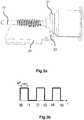
- the figure 1 is a schematic perspective view of a geared motor 100 comprising an electric motor 1 and a gear 2 and intended to drive for example a wiper system of a motor vehicle.
- the electric motor 1 comprises a stator 3 comprising stator plates 7 generally surrounded and protected by a carcass (not shown).
- the stator laminations 7 are configured to receive electromagnetic excitation coils 9.
- the electric motor 1 also comprises two bearings 11 (only one of the bearings 11 is visible on the figure 1 ) are arranged at both ends of a drive shaft 17.
- the bearings 11 make it possible to ensure the mechanical connection between the stator 3 and a rotor 15.
- Permanent magnets (not shown) are arranged on the drive shaft 17. mounted state of the electric motor 1, the permanent magnets are configured to come into contact with the electromagnetic excitation coils 9.
- the supply of the electromagnetic excitation coils 9 with appropriate control signals makes it possible to create a rotating field which causes rotating the rotor 15 via the permanent magnets.
- the electric motor 1 also comprises a control magnet 21 mounted on the drive shaft 17.
- the magnet 21 is multipolar and comprises at least one pair of magnetic poles.
- the control magnet 21 is intended to come into contact with at least one Hall effect sensor 23.
- the Hall effect sensor 23 is for example positioned on a printed circuit board 24 fixed on the stator 3
- the control magnet 21 may comprise several multipolar axial layers if a plurality of Hall effect sensors 23 are used. In the present case, three Hall effect sensors denoted 23a, 23b and 23c are respectively associated with three multipolar axial layers denoted 21a, 21b and 21c of the control magnet 21.
- the number of Hall effect sensors 23 is generally between 1 and 3.
- the Hall sensor (s) 23 is (are) configured to detect a magnetic pole of the control magnet 21 and by therefore an angular position of the control magnet 21.
- the electric motor 1 also comprises a control unit 25, represented on the figure 2 , and configured to receive the signals generated by the Hall effect sensor (s) 23 and to determine an angular position of the rotor 15 from the signals from said Hall effect sensor (s) 23.
- the control unit 25 may be implemented at the level of the printed circuit board 24.
- the control unit 25 is connected to the Hall sensor (s) 23 for example via a printed circuit or by a wired connection or by wireless communication means known to those skilled in the art.
- the control unit 25 is also configured to generate control signals from the angular position of the determined rotor. These control signals are used to supply the electromagnetic excitation coils 9 of the stator 3 in order to cause the rotor 15 to rotate.
- the control unit 25 comprises a clock 26 and is configured to estimate the position. angular rotor 15 between two signal state changes or signals from the Hall effect sensor (s) 23.
- the control unit 25 Preferably, only the signals from a single Hall effect sensor 23 are used by the control unit 25 to estimate the intermediate angular positions to avoid inserting an error in the estimate due to positioning tolerances of the others. Hall effect sensors 23.
- a single Hall effect sensor 23 will be used to estimate the intermediate angular positions, but it is also possible to use the signals from several Hall effect sensors. 23 without departing from the scope of the present invention. Tolerance errors can also be corrected by calibration.
- control magnet 21 comprises a pair of magnetic poles but it is also possible to use a control magnet 21 comprising a larger number of pairs of magnetic poles without leaving the of the present invention.
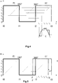
- the figure 3a represents an example of a control magnet 21 mounted on the shaft 17 of the rotor 15 comprising a pair of magnetic poles and the figure 3b represents the signal H from the Hall effect sensor 23 over time when the rotational speed of the rotor 15 supporting the control magnet 21 is constant.
- Two changes of state (the times of the changes of state being referenced 10, I1 ... I5) of the Hall effect sensor 23 correspond in this case to a rotation of 180 ° of the rotor 15.
- the control unit 25 can estimate the speed of rotation of the rotor 15 by, for example , at two previous state changes of the signal H from the Hall effect sensor 23.
- the angular position of the rotor 15 at each clock instant 26 can be estimated.
- the figure 4 represents an example of a graph representing the signal H from the Hall effect sensor 23 between the instants I0 and I2 of the state changes of the Hall effect sensor 23 of the figure 3a .
- time I2 it is possible from instants I0 and I1, for example, to estimate the instant I3 corresponding to the next change of state, for example by considering that the time interval I2-I3 is equal to I0-I1 time interval (assumption of a constant speed, which can often be assumed because of the inertia of the rotor 15).
- the time interval I2-I3 is equal to I0-I1 time interval (assumption of a constant speed, which can often be assumed because of the inertia of the rotor 15).
- I0-I1 time interval assumption of a constant speed, which can often be assumed because of the inertia of the rotor 15.
- these values can be generated by the control unit 25 from a predetermined mathematical equation.
- the greater the number of intermediate moments chosen the more the control signal obtained will be close to a sinusoidal signal.
- the figure 4 represents an example of a control signal C obtained by considering the intermediate moments i 21 to i 25 . Indeed, the signal obtained is quasi-sinusoidal or substantially sinusoidal since a single value is applied to the control signal between two intermediate moments, however, if the duration between two intermediate instants i 21 ... i 25 is sufficiently low, the control signal C obtained approaches a sinusoidal signal.
- the estimation of I3 and intermediate points i 21 ... i 25 can take into account not only the instants I0 and I1 but also the previous instants.
- a regression for example a polynomial or hyperbolic or other regression, may in particular be applied to determine a function corresponding to the evolution of the speed so as to determine the evolution of the speed between the instants I2 and I3.
- This determination is then repeated over time taking into account the instants of the new state changes, for example at each instant corresponding to a change of state of the signal H supplied by the Hall effect sensor 23.
- the information corresponding to the interval I1-I2 can be used (for example in combination with the interval I0-I1) to determine the instant I4 and the intermediate moments between I3 and I4.
- phase advance of the sinusoidal control signal C created.
- the figure 5 represents a diagram on which instants I'2 and I'3 are created by a time shift ⁇ T from instants I2 and I3, which also makes it possible to obtain intermediate instants i '21 ... i' 25 shifted and therefore to obtain a sinusoidal control signal C with a phase advance.
- This phase advance makes it possible to increase the torque supplied by the electric motor 1, the phase advance can be chosen according to the desired torque.
- the phase advance is for example applied when the rotation speed of the rotor 15 exceeds a predetermined threshold, here called the second predetermined threshold, and / or the desired torque exceeds a predetermined threshold.
- the application of a control signal C with a phase advance therefore depends on the torque to be supplied.
- control unit 25 can be configured to control the electric motor 1 by block control as long as the rotational speed is lower than a first predetermined threshold, for example 10% of the maximum rotational speed of the motor. rotor 15.
- the control unit 25 can use the signal or the signals coming from the Hall effect sensor (s).
- the electric motor 1 can for example comprise three Hall effect sensors. spaced from each other by 120 ° around a control magnet 21 comprising a pair of magnetic poles and providing the angular position of the rotor 15 every 60 ° to determine the switching times for the block drive or using three Hall effect sensors and a control magnet 21 comprising three multipolar axial layers arranged to allow detection of the angular position of the rotor 15 every 60 °
- a reduced number of Hall effect sensors 23, for example a single Hall effect sensor 23 can be used with a control magnet 21 comprising three pairs of poles in order to detect an angular position of the rotor every 60 ° and thus to determine switching times.
- Such block control allows a starting of the electric motor 1 with a large torque.
- Such a possibility is important in the case where the electric motor 1 is used in a geared motor of a wiper device for a motor vehicle, especially when the wiper blades strongly adhere to the windshield due to dirt or dirt. gel.
- the sinusoidal control as described above is applied.
- Such a sinusoidal (or quasi-sinusoidal) control makes it possible to obtain high torque at high speed and to obtain a smoother operation and thus to limit the noise of the electric motor 1.
- the large torque makes it possible to obtain a good operation of the wiper device even in case of dry windshield for example and the reduction of the noise emitted by the electric motor 1 improves the comfort of the passengers of the vehicle.
- the present invention also relates to a geared motor in which the electric motor is coupled to a reduction mechanism and a wiper system using the electric motor 1 described above, the output shaft of the reducing mechanism being for example connected to a control arm. windscreen wiper, possibly through a wheelhouse.
- the present invention also relates to a method for controlling a brushless direct current electric motor 1.
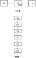
- the figure 6 represents the different steps of the process. Some steps may be optional and the order of steps may also differ, with some steps being simultaneous.
- the preliminary step 100 relates to the saving of a correspondence table between angular positions of the rotor 15 and associated control voltages for different commands of the electric motor 1.
- mathematical functions can be saved to enable the voltages of the motor to be calculated.
- Different mathematical functions can be associated with different commands of the motor 1 according to the desired rotational speed.
- the first step 101 consists of establishing a block command at the start of the electric motor 1 and up to a rotational speed of the electric motor 1 corresponding to a first predetermined threshold, for example 10% of the maximum rotational speed.
- the block control is established by determining the angular position of the rotor 15 (and hence the switching times) from the signal from at least one Hall effect sensor 23, generally three Hall effect sensors 23.
- the second step 102 concerns the estimation of the angular position of the rotor 15 at predetermined times between two instants corresponding to the changes of state of a Hall effect sensor 23.
- the signal coming from one of the Hall effect sensors 23 is selected and the angular position of the rotor 15 is estimated between the instants of change of state of the Hall effect sensor 23.
- This estimation is for example carried out as soon as the electric motor 1 has reached a rotation speed corresponding to a predefined value lower than the threshold defined in step 101, for example 8% of the maximum rotational speed.
- the estimation consists of estimating a rotational speed or an evolution of the rotational speed of the electric motor 1 from the instants of the previous changes of state and of applying the same speed of rotation or the same evolution of the speed of rotation. over the time interval until the moment of the next state change of the signal H from the Hall effect sensor 23. This determination can be repeated and updated with each new change of state of the Hall effect sensor 23.
- the estimation can also be made over a time interval corresponding to several changes in the state of the signal from the Hall effect sensor 23, for example over a time interval of two changes of state corresponding to a rotation of 360 Of the electric motor in the case of a control magnet comprising two magnetic poles.
- the rotational speed or evolution of the estimated rotational speed makes it possible to determine the angular position of the rotor 15 at each instant and in particular at selected predetermined moments.
- the third step 103 relates to the determination of a voltage value associated with each predetermined instant selected.
- the voltage values associated with the different positions of the rotor 15 to obtain a sinusoidal control signal C corresponding to the control of the electric motor 1 are saved in a memory of the control unit 25.
- these voltage values can be calculated by the control unit 25 from a mathematical function depending on the angular position of the rotor 15. Different mathematical functions can be associated with different engine control electrical 1 according to the desired speed of rotation for example.
- the fourth step 104 relates to the generation of a pseudo-sinusoidal control signal C from the voltage values determined in step 103.
- This control signal C generated is transmitted to the electromagnetic excitation coils 9 when the rotational speed the rotor 15 of the electric motor 1 is greater than the first predetermined threshold to produce a rotating field and drive the rotor 15 in rotation.
- the fifth step 105 is an optional step and concerns the generation of a substantially sinusoidal control signal C with a predetermined phase advance when the rotational speed of the rotor 15 exceeds a second predetermined threshold and / or when the torque to be supplied exceeds a predetermined threshold. predetermined value.
- the value of the phase advance can vary depending on the rotation speed and / or the torque to be provided so that the greater the rotation and / or the torque to be supplied, the greater the phase advance.
- the phase advance is obtained by inserting a time offset at the intermediate moments so that the voltage values determined in step 103 are applied with a lead time ⁇ T as previously described from the Figures 4 and 5 .
- such a control method makes it possible to obtain a high torque at startup and at high speeds of rotation if necessary while providing a quieter operation than with a block drive.
- such a method does not require expensive additional equipment such as an accurate encoder.
Applications Claiming Priority (1)
| Application Number | Priority Date | Filing Date | Title |
|---|---|---|---|
| FR1752535A FR3064427B1 (fr) | 2017-03-27 | 2017-03-27 | Moteur electrique, moto-reducteur, systeme d'essuyage et procede de commande associe |
Publications (1)
| Publication Number | Publication Date |
|---|---|
| EP3382886A1 true EP3382886A1 (de) | 2018-10-03 |
Family
ID=59153054
Family Applications (1)
| Application Number | Title | Priority Date | Filing Date |
|---|---|---|---|
| EP18163218.3A Withdrawn EP3382886A1 (de) | 2017-03-27 | 2018-03-22 | Elektromotor, getriebemotor, wischsystem und entsprechendes steuerverfahren |
Country Status (5)
| Country | Link |
|---|---|
| US (1) | US10432114B2 (de) |
| EP (1) | EP3382886A1 (de) |
| JP (1) | JP2018191497A (de) |
| CN (1) | CN108667254B (de) |
| FR (1) | FR3064427B1 (de) |
Families Citing this family (3)
| Publication number | Priority date | Publication date | Assignee | Title |
|---|---|---|---|---|
| FR3066970B1 (fr) * | 2017-06-02 | 2021-01-01 | Valeo Systemes Dessuyage | Moto-reducteur pour systeme d'essuyage de vehicule automobile |
| WO2020224645A1 (zh) * | 2019-05-08 | 2020-11-12 | 上海禹点电子科技有限公司 | 一种雨刮的调速控制系统 |
| FR3121984B1 (fr) * | 2021-04-14 | 2023-04-14 | Vitesco Technologies | Procédé pour s’adapter aux tolérances d’un système comportant un capteur de position et une cible tournante |
Citations (1)
| Publication number | Priority date | Publication date | Assignee | Title |
|---|---|---|---|---|
| EP2840700A1 (de) * | 2012-04-16 | 2015-02-25 | Mitsuba Corporation | Bürstenloser motor und wischervorrichtung |
Family Cites Families (8)
| Publication number | Priority date | Publication date | Assignee | Title |
|---|---|---|---|---|
| WO1995024071A1 (en) * | 1994-03-03 | 1995-09-08 | Iomega Corporation | Servo motor controller using position interpolation |
| US6239564B1 (en) * | 1998-10-06 | 2001-05-29 | H.R. Textron, Inc. | State advance controller commutation loop for brushless D.C. motors |
| KR100628588B1 (ko) * | 2003-02-21 | 2006-09-26 | 마츠시타 덴끼 산교 가부시키가이샤 | 모터 구동 장치, 공기 조화기, 냉장고, 극저온 냉동기,급탕기 및 휴대 전화 |
| JP2011010401A (ja) * | 2009-06-24 | 2011-01-13 | Jtekt Corp | モータ制御装置および電動パワーステアリング装置 |
| KR101240140B1 (ko) * | 2009-09-01 | 2013-03-07 | 주식회사 만도 | 로터 위치 감지장치, 방법 및 그를 이용한 전동식 파워스티어링 시스템 |
| JP5824660B2 (ja) * | 2010-07-12 | 2015-11-25 | パナソニックIpマネジメント株式会社 | 位相ずれ検出装置、モータ駆動装置、およびブラシレスモータ、並びに位相ずれ検出方法 |
| KR101927693B1 (ko) * | 2012-01-26 | 2018-12-12 | 삼성전자 주식회사 | 전동기의 센서리스 제어 장치 및 방법 |
| JP2016111920A (ja) * | 2014-11-26 | 2016-06-20 | 株式会社リコー | 永久磁石型モータ、位置推定装置及びモータ駆動制御装置 |
-
2017
- 2017-03-27 FR FR1752535A patent/FR3064427B1/fr active Active
-
2018
- 2018-03-22 EP EP18163218.3A patent/EP3382886A1/de not_active Withdrawn
- 2018-03-26 JP JP2018058353A patent/JP2018191497A/ja active Pending
- 2018-03-27 US US15/936,562 patent/US10432114B2/en active Active
- 2018-03-27 CN CN201810257293.XA patent/CN108667254B/zh active Active
Patent Citations (1)
| Publication number | Priority date | Publication date | Assignee | Title |
|---|---|---|---|---|
| EP2840700A1 (de) * | 2012-04-16 | 2015-02-25 | Mitsuba Corporation | Bürstenloser motor und wischervorrichtung |
Non-Patent Citations (3)
| Title |
|---|
| KIM JONGHWA ET AL: "Position Estimation Using Linear Hall Sensors for Permanent Magnet Linear Motor Systems", IEEE TRANSACTIONS ON INDUSTRIAL ELECTRONICS, IEEE SERVICE CENTER, PISCATAWAY, NJ, USA, vol. 63, no. 12, 1 December 2016 (2016-12-01), pages 7644 - 7652, XP011633598, ISSN: 0278-0046, [retrieved on 20161108], DOI: 10.1109/TIE.2016.2591899 * |
| RUIQING MA ET AL: "A novel sinusoidal current driving method for BLDCM based on SVPWM", ELECTRICAL MACHINES AND SYSTEMS (ICEMS), 2010 INTERNATIONAL CONFERENCE ON, IEEE, PISCATAWAY, NJ, USA, 10 October 2010 (2010-10-10), pages 732 - 735, XP031832835, ISBN: 978-1-4244-7720-3 * |
| SREEJITH KUMAR N ET AL: "Quasi sinusoid commutation for BLDC motor A simplified approach on 16 bit microcontroller platform", POWER ELECTRONICS, DRIVES AND ENERGY SYSTEMS (PEDES), 2012 IEEE INTERNATIONAL CONFERENCE ON, IEEE, 16 December 2012 (2012-12-16), pages 1 - 9, XP032346363, ISBN: 978-1-4673-4506-4, DOI: 10.1109/PEDES.2012.6484306 * |
Also Published As
| Publication number | Publication date |
|---|---|
| CN108667254B (zh) | 2020-09-01 |
| JP2018191497A (ja) | 2018-11-29 |
| FR3064427A1 (fr) | 2018-09-28 |
| US20180294750A1 (en) | 2018-10-11 |
| FR3064427B1 (fr) | 2021-10-22 |
| US10432114B2 (en) | 2019-10-01 |
| CN108667254A (zh) | 2018-10-16 |
Similar Documents
| Publication | Publication Date | Title |
|---|---|---|
| EP1881594B1 (de) | Verfahren zur Justierung der Parameter eines Synchronmotors und Verwendung eines solchen Verfahrens in einer Drehzahlregelung | |
| EP3516764B1 (de) | Getriebemotor, zugehöriges wischersystem und zugehöriges steuerungsverfahren | |
| EP3382886A1 (de) | Elektromotor, getriebemotor, wischsystem und entsprechendes steuerverfahren | |
| WO2018091302A1 (fr) | Moto-reducteur, systeme d'essuyage et procede de commande associes | |
| FR2894735A1 (fr) | Generateur-moteur synchrone a enroulement de champ | |
| FR3062762A1 (fr) | Procede d'estimation de la position angulaire d’un rotor d’un systeme d’entrainement electrique | |
| FR2999038A1 (fr) | Installation de commande et procede pour determiner l'angle du rotor d'une machine synchrone | |
| WO2020001904A1 (fr) | Moteur electrique a courant continu sans balai et procede de commande associe | |
| EP1285490A1 (de) | Verfahren zur bestimmung der rotorposition eines kollektorlosen elektromagnetischen motors und vorrichtung zur durchführung eines solchen verfahrens | |
| JP5405903B2 (ja) | 車両用電装品の制御装置 | |
| EP3382887A1 (de) | Startverfahren für eine synchronmaschine, steuervorrichtung, entsprechende synchronmaschine und entsprechender kompressor | |
| FR2908246A1 (fr) | Moteur electrique a courant continu et procede de controle de la position angulaire d'un tel moteur | |
| EP3394978B1 (de) | Pseudosinusoidales steuerungsverfahren zur steuerung eines elektrischen synchronmotors | |
| WO2020002553A1 (fr) | Moteur electrique a courant continu sans balai et procede de commande associe | |
| FR2864722A1 (fr) | Procede d'exploitation d'informations de vitesse de rotation et de position de rotation d'un moteur a courant continu | |
| EP3815239A1 (de) | Bürstenloser gleichstrom-elektromotor und zugehöriges steuerungsverfahren | |
| WO2017129902A1 (fr) | Étalement spectral pour moteur électrique | |
| FR3128598A1 (fr) | Procédé de calage automatique d'un capteur de position angulaire | |
| FR3049410A1 (fr) | Procede de demarrage pour une machine synchrone, dispositif de commande, machine synchrone, et compresseur associes. | |
| FR3121984A1 (fr) | Procédé pour s’adapter aux tolérances d’un système comportant un capteur de position et une cible tournante | |
| FR3131993A1 (fr) | Dispositif et procédé de commande d’une machine synchrone et d’estimation de la position rotor, du démarrage à une faible vitesse prédéterminée | |
| FR2843248A1 (fr) | Procede de commande de fonctionnement synchronise d'au moins deux moteurs electriques polyphases | |
| WO2016098032A1 (fr) | Procédé et dispositif d'évaluation de paramètres de fonctionnement ainsi que processus et systeme de commande d'une machine synchrone | |
| FR2517088A1 (fr) | Commande electrique pour reguler la vitesse et/ou la position d'une charge entrainee a tres faible vitesse de rotation |
Legal Events
| Date | Code | Title | Description |
|---|---|---|---|
| PUAI | Public reference made under article 153(3) epc to a published international application that has entered the european phase |
Free format text: ORIGINAL CODE: 0009012 |
|
| STAA | Information on the status of an ep patent application or granted ep patent |
Free format text: STATUS: REQUEST FOR EXAMINATION WAS MADE |
|
| 17P | Request for examination filed |
Effective date: 20180322 |
|
| AK | Designated contracting states |
Kind code of ref document: A1 Designated state(s): AL AT BE BG CH CY CZ DE DK EE ES FI FR GB GR HR HU IE IS IT LI LT LU LV MC MK MT NL NO PL PT RO RS SE SI SK SM TR |
|
| AX | Request for extension of the european patent |
Extension state: BA ME |
|
| STAA | Information on the status of an ep patent application or granted ep patent |
Free format text: STATUS: EXAMINATION IS IN PROGRESS |
|
| 17Q | First examination report despatched |
Effective date: 20200218 |
|
| STAA | Information on the status of an ep patent application or granted ep patent |
Free format text: STATUS: THE APPLICATION IS DEEMED TO BE WITHDRAWN |
|
| 18D | Application deemed to be withdrawn |
Effective date: 20200829 |