EP3382131A1 - Gate and actuating module for a gate - Google Patents
Gate and actuating module for a gate Download PDFInfo
- Publication number
- EP3382131A1 EP3382131A1 EP17201004.3A EP17201004A EP3382131A1 EP 3382131 A1 EP3382131 A1 EP 3382131A1 EP 17201004 A EP17201004 A EP 17201004A EP 3382131 A1 EP3382131 A1 EP 3382131A1
- Authority
- EP
- European Patent Office
- Prior art keywords
- movement
- shaft
- actuating
- door leaf
- storage device
- Prior art date
- Legal status (The legal status is an assumption and is not a legal conclusion. Google has not performed a legal analysis and makes no representation as to the accuracy of the status listed.)
- Granted
Links
- 230000033001 locomotion Effects 0.000 claims abstract description 73
- 230000005540 biological transmission Effects 0.000 claims abstract description 25
- 230000001404 mediated effect Effects 0.000 claims abstract description 3
- 230000008878 coupling Effects 0.000 claims description 7
- 238000010168 coupling process Methods 0.000 claims description 7
- 238000005859 coupling reaction Methods 0.000 claims description 7
- 239000002655 kraft paper Substances 0.000 description 5
- 230000005484 gravity Effects 0.000 description 4
- 238000006073 displacement reaction Methods 0.000 description 1
- 230000000694 effects Effects 0.000 description 1
- 238000004146 energy storage Methods 0.000 description 1
- 230000007257 malfunction Effects 0.000 description 1
- 238000009420 retrofitting Methods 0.000 description 1
- 238000004804 winding Methods 0.000 description 1
Images


Classifications
-
- E—FIXED CONSTRUCTIONS
- E05—LOCKS; KEYS; WINDOW OR DOOR FITTINGS; SAFES
- E05D—HINGES OR SUSPENSION DEVICES FOR DOORS, WINDOWS OR WINGS
- E05D13/00—Accessories for sliding or lifting wings, e.g. pulleys, safety catches
- E05D13/10—Counterbalance devices
- E05D13/12—Counterbalance devices with springs
- E05D13/1253—Counterbalance devices with springs with canted-coil torsion springs
- E05D13/1261—Counterbalance devices with springs with canted-coil torsion springs specially adapted for overhead wings
-
- E—FIXED CONSTRUCTIONS
- E05—LOCKS; KEYS; WINDOW OR DOOR FITTINGS; SAFES
- E05D—HINGES OR SUSPENSION DEVICES FOR DOORS, WINDOWS OR WINGS
- E05D13/00—Accessories for sliding or lifting wings, e.g. pulleys, safety catches
- E05D13/003—Anti-dropping devices
-
- E—FIXED CONSTRUCTIONS
- E05—LOCKS; KEYS; WINDOW OR DOOR FITTINGS; SAFES
- E05D—HINGES OR SUSPENSION DEVICES FOR DOORS, WINDOWS OR WINGS
- E05D13/00—Accessories for sliding or lifting wings, e.g. pulleys, safety catches
- E05D13/10—Counterbalance devices
- E05D13/12—Counterbalance devices with springs
-
- E—FIXED CONSTRUCTIONS
- E05—LOCKS; KEYS; WINDOW OR DOOR FITTINGS; SAFES
- E05F—DEVICES FOR MOVING WINGS INTO OPEN OR CLOSED POSITION; CHECKS FOR WINGS; WING FITTINGS NOT OTHERWISE PROVIDED FOR, CONCERNED WITH THE FUNCTIONING OF THE WING
- E05F15/00—Power-operated mechanisms for wings
- E05F15/60—Power-operated mechanisms for wings using electrical actuators
- E05F15/603—Power-operated mechanisms for wings using electrical actuators using rotary electromotors
- E05F15/665—Power-operated mechanisms for wings using electrical actuators using rotary electromotors for vertically-sliding wings
- E05F15/668—Power-operated mechanisms for wings using electrical actuators using rotary electromotors for vertically-sliding wings for overhead wings
- E05F15/681—Power-operated mechanisms for wings using electrical actuators using rotary electromotors for vertically-sliding wings for overhead wings operated by flexible elongated pulling elements, e.g. belts
- E05F15/686—Power-operated mechanisms for wings using electrical actuators using rotary electromotors for vertically-sliding wings for overhead wings operated by flexible elongated pulling elements, e.g. belts by cables or ropes
-
- E—FIXED CONSTRUCTIONS
- E05—LOCKS; KEYS; WINDOW OR DOOR FITTINGS; SAFES
- E05Y—INDEXING SCHEME RELATING TO HINGES OR OTHER SUSPENSION DEVICES FOR DOORS, WINDOWS OR WINGS AND DEVICES FOR MOVING WINGS INTO OPEN OR CLOSED POSITION, CHECKS FOR WINGS AND WING FITTINGS NOT OTHERWISE PROVIDED FOR, CONCERNED WITH THE FUNCTIONING OF THE WING
- E05Y2201/00—Constructional elements; Accessories therefore
- E05Y2201/20—Brakes; Disengaging means, e.g. clutches; Holders, e.g. locks; Stops; Accessories therefore
- E05Y2201/214—Disengaging means
- E05Y2201/216—Clutches
-
- E—FIXED CONSTRUCTIONS
- E05—LOCKS; KEYS; WINDOW OR DOOR FITTINGS; SAFES
- E05Y—INDEXING SCHEME RELATING TO HINGES OR OTHER SUSPENSION DEVICES FOR DOORS, WINDOWS OR WINGS AND DEVICES FOR MOVING WINGS INTO OPEN OR CLOSED POSITION, CHECKS FOR WINGS AND WING FITTINGS NOT OTHERWISE PROVIDED FOR, CONCERNED WITH THE FUNCTIONING OF THE WING
- E05Y2201/00—Constructional elements; Accessories therefore
- E05Y2201/20—Brakes; Disengaging means, e.g. clutches; Holders, e.g. locks; Stops; Accessories therefore
- E05Y2201/23—Actuation thereof
- E05Y2201/232—Actuation thereof by automatically acting means
- E05Y2201/236—Actuation thereof by automatically acting means using force or torque
-
- E—FIXED CONSTRUCTIONS
- E05—LOCKS; KEYS; WINDOW OR DOOR FITTINGS; SAFES
- E05Y—INDEXING SCHEME RELATING TO HINGES OR OTHER SUSPENSION DEVICES FOR DOORS, WINDOWS OR WINGS AND DEVICES FOR MOVING WINGS INTO OPEN OR CLOSED POSITION, CHECKS FOR WINGS AND WING FITTINGS NOT OTHERWISE PROVIDED FOR, CONCERNED WITH THE FUNCTIONING OF THE WING
- E05Y2201/00—Constructional elements; Accessories therefore
- E05Y2201/20—Brakes; Disengaging means, e.g. clutches; Holders, e.g. locks; Stops; Accessories therefore
- E05Y2201/252—Brakes; Disengaging means, e.g. clutches; Holders, e.g. locks; Stops; Accessories therefore characterised by type of friction
- E05Y2201/26—Mechanical friction
-
- E—FIXED CONSTRUCTIONS
- E05—LOCKS; KEYS; WINDOW OR DOOR FITTINGS; SAFES
- E05Y—INDEXING SCHEME RELATING TO HINGES OR OTHER SUSPENSION DEVICES FOR DOORS, WINDOWS OR WINGS AND DEVICES FOR MOVING WINGS INTO OPEN OR CLOSED POSITION, CHECKS FOR WINGS AND WING FITTINGS NOT OTHERWISE PROVIDED FOR, CONCERNED WITH THE FUNCTIONING OF THE WING
- E05Y2201/00—Constructional elements; Accessories therefore
- E05Y2201/60—Suspension or transmission members; Accessories therefore
- E05Y2201/622—Suspension or transmission members elements
- E05Y2201/676—Transmission of human force
- E05Y2201/678—Hand chains
-
- E05Y2400/3013—
-
- E—FIXED CONSTRUCTIONS
- E05—LOCKS; KEYS; WINDOW OR DOOR FITTINGS; SAFES
- E05Y—INDEXING SCHEME RELATING TO HINGES OR OTHER SUSPENSION DEVICES FOR DOORS, WINDOWS OR WINGS AND DEVICES FOR MOVING WINGS INTO OPEN OR CLOSED POSITION, CHECKS FOR WINGS AND WING FITTINGS NOT OTHERWISE PROVIDED FOR, CONCERNED WITH THE FUNCTIONING OF THE WING
- E05Y2900/00—Application of doors, windows, wings or fittings thereof
- E05Y2900/10—Application of doors, windows, wings or fittings thereof for buildings or parts thereof
- E05Y2900/106—Application of doors, windows, wings or fittings thereof for buildings or parts thereof for garages
Definitions
- the invention relates to a gate with a movable between a closed position and an open position door leaf, a preferably rope-shaped, in particular wire-shaped and coupled to the door leaf force transmission means for transmitting an opening force on the door leaf, a movable storage device of the force transmission means in the course of a closing movement of the door leaf a release movement is released and received in the course of an opening movement by a receiving movement and a coupled to the storage device manually operated actuator, with the release movement and the receiving movement of the storage device is mediated in the course of a closing movement or opening movement of the door leaf.
- the door leaf is regularly arranged in the closed position approximately in a vertical plane and arranged in the open position above the head usually in a horizontal plane.
- the door leaf can be made in one piece.
- it comprises a plurality of door leaf elements which extend perpendicular to the door leaf movement direction Joint axes are hinged together.
- Such gates as they can be used in the context of the invention are, for example, in the EP 370376 A1 disclosed.
- Such a weight compensating device may, for example, be designed as a torsion spring, which rotates a torsion spring shaft, which is usually arranged above the opening to be closed by the door leaf and extends approximately perpendicular to the direction of the door leaf movement.
- a torsion spring which rotates a torsion spring shaft, which is usually arranged above the opening to be closed by the door leaf and extends approximately perpendicular to the direction of the door leaf movement.
- one end of the torsion spring is held stationary, while the other end is coupled to the rotatably mounted torsion spring shaft.
- a storage device in the form of a cable drum can be arranged coaxially with the torsion spring shaft, from which a cable, in particular wire rope, coupled to the door leaf is unwound in the course of the closing movement of the door leaf by rotating the torsion spring shaft.
- the rotation of the Torsionsfederwelle in the course of the closing movement causes a tension of the torsion spring.
- the stored energy in the tensioned torsion spring is then available to assist the opening movement of the door leaf.
- the force exerted by the torsion spring is transmitted via the unwound from the storage device forming a cable drum power transmission means in the form of a wire rope on the door leaf.
- a release movement of running as a cable drum storage device On the other hand, coupled to the door leaf rope in the course of an opening movement by the supported by the torsion spring rotation of Reel drum wound in a direction opposite to the release movement again on the cable drum.
- the corresponding movement of the cable drum is referred to as a picking movement.
- an actuator may be provided with a coaxial with the cable drum and rotatably connected sprocket.
- the sprocket may be circulated by a hand chain that meshes with the sprocket.
- a hand chain that meshes with the sprocket.
- a rotary motion is transmitted to the sprocket and thus also to the cable drum.
- a wire releasing releasing movement of the storage device or a leading to winding the wire rope receiving movement of the cable drum in the context of a closing or opening movement of the gate mediates.
- a so-called cable break catch device is sometimes activated, in particular during a closing movement, when the force exerted by the door leaf under the effect of gravity on the force transmission means falls below a predetermined value. Then another Torblattiolo is stopped, while under certain circumstances, a release movement of the storage device takes place with the other areas of the power transmission means are released. This causes a malfunction of the door, which can be eliminated only by service technicians.
- the invention has the object to ensure the reliable operation of generic gates without the use of service technicians.
- this object is achieved by a development of the known goals, which is characterized essentially by the fact that the actuator, for example, a rotating from a hand chain and with respect to a parallel, in particular coaxial with the Torsionsfederwelle rotatable operating wheel, such as a sprocket belt pulley or a Having pulley, a limiting device for limiting the force transmitted from the actuator to the memory device and / or of the actuating device to the memory device transferable moment of motion, in particular torque, assigned.
- the actuator for example, a rotating from a hand chain and with respect to a parallel, in particular coaxial with the Torsionsfederwelle rotatable operating wheel, such as a sprocket belt pulley or a Having pulley
- a limiting device for limiting the force transmitted from the actuator to the memory device and / or of the actuating device to the memory device transferable moment of motion, in particular torque, assigned.
- the available force (gravity, spring buffer) urging the door panel to the closed position may not be enough to accelerate the door panel sufficiently quickly so that it is accelerated in accordance with the release of the power transmission means in the direction of the closed position. Then, the weight force of the door leaf does not exert sufficient force on the power transmission means.
- the power transmission means in the form of a wire rope passes after release from the storage device unwound from the storage without slack between the storage device and the door leaf, resulting in the triggering of a cable breaker, which in turn stops the Torblattiolo, while other areas the power transmission means are released from the storage device or other sections of the wire rope are unwound from the cable drum.
- This can also cause the wire rope can not be wound in a controlled manner on the cable drum, because it runs chaotically between the cable drum and the coupling point on the door leaf without biasing force.
- the speed of the release of the power transmission means of the memory device is limited because the coupling between actuator on the one hand and memory device on the other hand when large forces occur, as may occur when jerky tightening the hand-operated actuator, separated and the actuator then independent of the storage unit is moved.
- overly rapid release of the power transmission means from the memory device can be prevented and a sufficient voltage of the power transmission means between the coupling point on the door leaf and the memory device can be ensured.
- the opening speed of the door leaf can be limited by the limiting device.
- the power transmission means or cable should be wound on the cable drum at an excessively high speed, resulting in a correspondingly high opening speed, the actuator being separated from the storage means by means of the limiting means. This can avoid that the door leaf runs when reaching the open position at an excessively high speed against a corresponding stop or spring buffer. Also damage to the gate can be avoided.
- the force transmission means according to the invention is preferably cord-shaped, in particular designed in the form of a wire rope, while the gates Storage device has a drum drum with respect to a rotatable drum, released by the rope in the course of a closing movement and on which the rope is wound in the course of an opening movement.
- the drum axis runs approximately perpendicular to the direction of movement of the door.
- the drum can also be designed frustoconical, so that at the beginning of a closing movement a shorter cable length per revolution of the cable drum is released from the cable drum than at the end of the closing movement. This takes into account the fact that less closing force is available at the beginning of the closing movement than at the end of the closing movement.
- the actuating device may be a possibly by a hand chain, a hand belt, such as a toothed belt, or a hand rope circulating and this meshing operating wheel to rotate, the cable drum and the operating wheel are preferably rotatable relative to a common axis of rotation, also is intended to the use of gearboxes with axial offset between the input and output shaft, and at least the cable drum with respect to a shaft extending coaxially to the axis of rotation, such as a torsion spring shaft is fixed.
- the cable drum is rotatably connected to the shaft. This can be achieved by a positive connection.
- the actuating wheel realized, for example, as a sprocket, belt pulley or pulley is, if appropriate, indirectly connected indirectly to the shaft via a friction clutch separating upon reaching a predetermined torque.
- the operating wheel can be arranged for example on a non-rotatably connected to the shaft stub shaft, wherein the friction clutch transmits a rotational movement of the sprocket on the stub shaft before reaching a predetermined torque, which in turn is rotatably connected to the shaft connected to the cable drum.
- the friction clutch separates the rotational movement of the sprocket from the stub shaft, so that the actuating wheel is then rotated independently of the stub shaft and thus also independent of the shaft.
- Slip clutches are used to compensate for the differences between a drive shaft and a hoist winch. According to DE 2027491 A1 is prevented with a slip clutch that the door leaf is urged with tensioned energy storage in engine operation in the closed position.
- the friction clutch at least one optionally connected via the shaft stub rotatably connected to the shaft and a voltage applied to a preferably approximately perpendicular to the axis of rotation end face of the actuating wheel friction disc and a biasing means for generating a biasing force with the friction disc and the operating wheel are urged against each other, on. If an axial movement of the actuating wheel is blocked along the shaft axis, a frictional engagement between the friction disc and the actuating wheel is achieved by the biasing force, the torque of the actuating wheel to the friction disc and thus to the shaft and the Cable drum allows while the friction is separated when the predetermined torque is exceeded.
- the friction clutch on two friction plates, between which the operating wheel is received of which at least one rotatably connected to the shaft or the stub shaft and at least one fixed in the axial direction with the shaft or stub shaft, or forms an axial stop for axial movement of the actuating wheel.
- the pretensioning device of a friction clutch according to the invention may have a diaphragm spring, which may possibly be indirectly connected via a clamping disk to the boundary surface of the friction disk facing away from the actuating wheel.
- the biasing means may comprise adjusting means for adjusting the force urging the friction disc against the operating wheel, so as to be able to adjust the predetermined torque at which the friction clutch separates.
- the adjusting device on a facing away from the friction disc boundary surface of the plate spring can be applied groove nut.
- an axial movement of the groove nut and thus an adjustment of the bias of the plate spring is effected.
- the shaft can have a torsion spring shaft which revolves around a torsion spring, wherein the torsion spring is tensioned in the course of the closing movement of the door leaf.
- the actuating device and the limiting device can be arranged on a releasably connected to the torsion spring shaft and in the assembled state coaxially extending stub shaft.
- actuator and limiting means may be detachably and interchangeably attached to the torsion spring shaft.
- An inventive actuation module designed for producing a door according to the invention by means of retrofitting already mounted doors accordingly has an actuation device and a delimiting device, wherein the delimiting device transmits one of the actuation device to a memory device for a force transmission means the force exercisable by the gate can be limited.
- the actuating device and the limiting device of an actuating module according to the invention are arranged on a shaft stub which can be detachably connected to the torsion spring shaft.
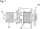
- Fig. 1 Tor shown has a weight balancing device with a torsion spring rotating around a torsion spring 12.
- One end of the torsion spring 12 is coupled to the rotatably mounted Torsionsfederwelle 10, while the other end of the torsion spring is fixedly mounted.
- the torsion spring shaft 10 By rotating the torsion spring shaft 10, which extends approximately in the horizontal direction over the head, the torsion spring is tensioned or relaxed.
- torsion spring serving as a storage device for a power transmission means in the form of a wire rope drum 20 is rotatably connected to the Torsionsfederwelle so that the wire during an opening movement, which leads to the tension of the torsion spring 12, unwound from the cable drum or during a closing movement of the door leaf , which is supported by the tensioned torsion spring 12, is wound on the cable drum.
- the actuation module 100 On the side facing away from the torsion spring 12 of the cable drum 20, an actuating module 100 according to the invention is mounted. As in Fig. 2 and 3 illustrated, the actuation module 100 has a rotatably coupled to the torsion spring shaft 10 stub shaft 120, which rotatably mounted on the Torsionsfederwelle via a coupling nose 122 which engages in a corresponding recess in the Torsionsfederwelle 10 and with the aid of bores 124 passing through nuts on the Torsionsfederwelle can be secured.
- the stub shaft 120 extends coaxially with the axis of the torsion spring shaft 10.
- a designed as a sprocket 130 operating wheel is placed, which is rotatable with respect to the axis of the Torsionsfederwelle.
- the rotational movement of the sprocket 130 is a total of 140 designated limiting device on the stub shaft 120 and thus also on the torsion spring shaft 10th transfer.
- the limiting device comprises a friction disc 142 designed as a brake disk, which abuts against an end face 132 of the sprocket 130 running perpendicular to the axis of the torsion spring shaft.
- the brake disc 142 is urged by means of a plate spring 144 against the end face 132 of the sprocket 130, which by means of a in Fig. 3 recognizable further brake disc 143, which abuts against the end face 132 opposite end face, is locked in the axial direction.
- the biasing force of the plate spring 144 is transmitted via a clamping disc 146 on the end face 132 of the sprocket 130.
- the biasing force is adjustable by means of a groove nut 148.
- the groove nut 148 on a shaft axis of the shaft stub 120 circumferential thread are screwed and so are offset in the axial direction.
- the plate spring 144 is biased so as to adjust a torque at which the friction clutch produced by the brake discs 142, 143 on the one hand and stub shaft 120 on the other hand is separated.
- the actuation module can also be produced in one piece with the torsion spring shaft 10. It is also thought to arrange the cable drum on the side facing away from the torsion spring side of the actuating module. Gates according to the invention can also be equipped with tension spring systems for weight compensation. It is also thought to use other transmission means instead of a wire rope. It is essential that an actuating device is provided, with which the force or the torque is limited, by which or the storage device for the power transmission means can be transmitted.
Abstract
Tor mit einem zwischen einer Schließstellung und einer Öffnungsstellung bewegbaren Torblatt, einem vorzugsweise seilförmigen, insbesondere drahtseilförmigen und an das Torblatt gekoppelten Kraftübertragungsmittel zum Übertragen einer Öffnungskraft auf das Torblatt, einer bewegbaren Speichereinrichtung, von der das Kraftübertragungsmittel im Verlauf einer Schließbewegung des Torblatts durch eine Freigabebewegung freigegeben und im Verlauf einer Öffnungsbewegung durch eine Aufnahmebewegung aufgenommen wird, und einer an die Speichereinrichtung gekoppelten Betätigungseinrichtung, mit der die Freigabebewegung und die Aufnahmebewegung der Speichereinrichtung im Verlauf der Schließbewegung bzw. der Öffnungsbewegung des Torblatts vermittelt wird, gekennzeichnet durch eine Begrenzungseinrichtung zur Begrenzung der von der Betätigungseinrichtung auf die Speichereinrichtung übertragbaren Kraft und/oder des von der Betätigungseinrichtung auf die Speichereinrichtung übertragbaren Bewegungsmoments, insbesondere Drehmoments.Gate with a movable between a closed position and an open position door leaf, a preferably rope-shaped, in particular wire rope-shaped and coupled to the door leaf force transmission means for transmitting an opening force on the door leaf, a movable storage device, released by the power transmission means in the course of a closing movement of the door leaf by a release movement and is received in the course of an opening movement by a receiving movement, and an actuating device coupled to the storage device, with which the release movement and the receiving movement of the storage device in the course of the closing movement or the opening movement of the door leaf is mediated, characterized by a limiting device for limiting the of the Actuating device transferable to the storage device force and / or transferable from the actuator to the storage device Movement torque, in particular torque.
Description
Die Erfindung betrifft ein Tor mit einem zwischen einer Schließstellung und einer Öffnungsstellung bewegbaren Torblatt, einem vorzugsweise seilförmigen, insbesondere drahtseilförmigen und an das Torblatt gekoppelten Kraftübertragungsmittel zum Übertragen einer Öffnungskraft auf das Torblatt, einer bewegbaren Speichereinrichtung von der das Kraftübertragungsmittel im Verlauf einer Schließbewegung des Torblatts durch eine Freigabebewegung freigegeben und im Verlauf einer Öffnungsbewegung durch eine Aufnahmebewegung aufgenommen wird und einer an die Speichereinrichtung gekoppelten handbetätigten Betätigungseinrichtung, mit der die Freigabebewegung und die Aufnahmebewegung der Speichereinrichtung im Verlauf einer Schließbewegung bzw. Öffnungsbewegung des Torblatts vermittelt wird.The invention relates to a gate with a movable between a closed position and an open position door leaf, a preferably rope-shaped, in particular wire-shaped and coupled to the door leaf force transmission means for transmitting an opening force on the door leaf, a movable storage device of the force transmission means in the course of a closing movement of the door leaf a release movement is released and received in the course of an opening movement by a receiving movement and a coupled to the storage device manually operated actuator, with the release movement and the receiving movement of the storage device is mediated in the course of a closing movement or opening movement of the door leaf.
Bei derartigen Toren, wie sie auch im Rahmen der Erfindung zum Einsatz kommen, ist das Torblatt in der Schließstellung regelmäßig etwa in einer Vertikalebene angeordnet und in der Öffnungsstellung über Kopf üblicherweise in einer Horizontalebene angeordnet. Das Torblatt kann einteilig ausgeführt sein. Im Fall von sogenannten Sektionaltoren umfasst es aber eine Mehrzahl von Torblattelementen, die bezüglich senkrecht zur Torblattbewegungsrichtung verlaufenden Gelenkachsen gelenkig miteinander verbunden sind. Derartige Tore, wie sie auch im Rahmen der Erfindung zum Einsatz kommen können, sind beispielsweise in der
Im Verlauf der Torblattöffnungsbewegung muss das Torblatt gegen die Schwerkraftwirkung angehoben und in die üblicherweise über Kopf angeordnete Öffnungsstellung bewegt werden. Diese Bewegung wird üblicherweise durch Führungsschienenanordnungen geführt. Ferner wird die Bewegung üblicherweise durch eine Gewichtsausgleichseinrichtung unterstützt, welche über das Kraftübertragungsmittel an das Torblatt gekoppelt ist und eine in Öffnungsrichtung wirkende Kraft auf das in der Schließstellung angeordnete Torblatt ausübt.In the course of Torblattöffnungsbewegung the door leaf must be raised against the force of gravity and moved into the usually over-head opening position. This movement is usually guided by guide rail arrangements. Further, the movement is usually supported by a weight balancing device which is coupled via the power transmission means to the door leaf and exerts an opening force acting on the arranged in the closed position door leaf.
Eine derartige Gewichtsausgleichseinrichtung kann beispielsweise als Torsionsfeder ausgeführt sein, die eine üblicherweise oberhalb der mit dem Torblatt zu verschließenden Öffnung angeordnete und etwa senkrecht zur Torblattbewegungsrichtung verlaufenden Torsionsfederwelle umläuft. Dabei ist ein Ende der Torsionsfeder ortsfest gehalten, während das andere Ende an die drehbar gelagerte Torsionsfederwelle gekoppelt ist. Koaxial zur Torsionsfederwelle kann dabei eine Speichereinrichtung in Form einer Seiltrommel angeordnet sein, von der ein andererseits an das Torblatt gekoppeltes Seil, insbesondere Drahtseil, im Verlauf der Schließbewegung des Torblatts durch Drehen der Torsionsfederwelle abgewickelt wird. Die Drehung der Torsionsfederwelle im Verlauf der Schließbewegung bewirkt eine Spannung der Torsionsfeder. Die in der gespannten Torsionsfeder gespeicherte Energie steht dann zur Unterstützung der Öffnungsbewegung des Torblatts zur Verfügung. Die von der Torsionsfeder ausgeübte Kraft wird über das von der eine Speichereinrichtung bildenden Seiltrommel abgewickelte Kraftübertragungsmittel in Form eines Drahtseils auf das Torblatt übertragen.Such a weight compensating device may, for example, be designed as a torsion spring, which rotates a torsion spring shaft, which is usually arranged above the opening to be closed by the door leaf and extends approximately perpendicular to the direction of the door leaf movement. In this case, one end of the torsion spring is held stationary, while the other end is coupled to the rotatably mounted torsion spring shaft. A storage device in the form of a cable drum can be arranged coaxially with the torsion spring shaft, from which a cable, in particular wire rope, coupled to the door leaf is unwound in the course of the closing movement of the door leaf by rotating the torsion spring shaft. The rotation of the Torsionsfederwelle in the course of the closing movement causes a tension of the torsion spring. The stored energy in the tensioned torsion spring is then available to assist the opening movement of the door leaf. The force exerted by the torsion spring is transmitted via the unwound from the storage device forming a cable drum power transmission means in the form of a wire rope on the door leaf.
Die Drehung der Seiltrommel im Verlauf der Schließbewegung, durch die das Drahtseil von der Seiltrommel freigegeben wird, stellt dabei eine Freigabebewegung der als Seiltrommel ausgeführten Speichereinrichtung dar. Andererseits wird das an das Torblatt gekoppelte Seil im Verlauf einer Öffnungsbewegung durch die von der Torsionsfeder unterstützte Drehung der Seiltrommel in einer der Freigabebewegung entgegengesetzten Richtung wieder auf die Seiltrommel aufgewickelt. Die entsprechende Bewegung der Seiltrommel wird als Aufnahmebewegung bezeichnet.The rotation of the cable drum in the course of the closing movement, by which the wire rope is released from the cable drum, thereby represents a release movement of running as a cable drum storage device. On the other hand, coupled to the door leaf rope in the course of an opening movement by the supported by the torsion spring rotation of Reel drum wound in a direction opposite to the release movement again on the cable drum. The corresponding movement of the cable drum is referred to as a picking movement.
Bei handbetätigten Toren kann eine Betätigungseinrichtung mit einem koaxial zur Seiltrommel angeordneten und drehfest damit verbundenen Kettenrad vorgesehen sein. Das Kettenrad kann von einer Handkette umlaufen sein, die das Kettenrad kämmt. Durch Ziehen an der Handkette wird eine Drehbewegung auf das Kettenrad und damit auch auf die Seiltrommel übertragen. Durch diese Drehung wird eine das Drahtseil freigebende Freigabebewegung der Speichereinrichtung bzw. ein zum Aufwickeln des Drahtseils führende Aufnahmebewegung der Seiltrommel im Rahmen einer Schließ- bzw. Öffnungsbewegung des Tors vermittelt.In manually operated gates, an actuator may be provided with a coaxial with the cable drum and rotatably connected sprocket. The sprocket may be circulated by a hand chain that meshes with the sprocket. By pulling on the hand chain a rotary motion is transmitted to the sprocket and thus also to the cable drum. By this rotation, a wire releasing releasing movement of the storage device or a leading to winding the wire rope receiving movement of the cable drum in the context of a closing or opening movement of the gate mediates.
Bei Einsatz entsprechender Tore, insbesondere handbetriebener Tore, wird insbesondere im Verlauf einer Schließbewegung bisweilen eine sogenannte Seilbruchfangvorrichtung aktiviert, wenn die von dem Torblatt unter Schwerkraftwirkung auf das Kraftübertragungsmittel ausgeübte Kraft einen vorgegebenen Wert unterschreitet. Dann wird eine weitere Torblattbewegung gestoppt, während unter Umständen noch eine Freigabebewegung der Speichereinrichtung erfolgt, mit der weitere Bereiche des Kraftübertragungsmittels freigegeben werden. Das bedingt eine Betriebsstörung des Tors, welche nur durch Servicetechniker beseitigt werden kann.When using appropriate gates, in particular manually operated gates, a so-called cable break catch device is sometimes activated, in particular during a closing movement, when the force exerted by the door leaf under the effect of gravity on the force transmission means falls below a predetermined value. Then another Torblattbewegung is stopped, while under certain circumstances, a release movement of the storage device takes place with the other areas of the power transmission means are released. This causes a malfunction of the door, which can be eliminated only by service technicians.
Angesichts dieser Probleme im Stand der Technik liegt der Erfindung die Aufgabe zugrunde, den zuverlässigen Betrieb gattungsgemäßer Tore ohne Einsatz von Servicetechnikern sicherzustellen.In view of these problems in the prior art, the invention has the object to ensure the reliable operation of generic gates without the use of service technicians.
Erfindungsgemäß wird diese Aufgabe durch eine Weiterbildung der bekannten Tore gelöst, die im Wesentlichen dadurch gekennzeichnet ist, dass der Betätigungseinrichtung, die beispielsweise ein von einer Handkette umlaufendes und bezüglich einer parallel, insbesondere koaxial zur Torsionsfederwelle drehbares Betätigungsrad, wie etwa ein Kettenrad eine Gurtscheibe oder eine Seilscheibe aufweisen kann, eine Begrenzungseinrichtung zur Begrenzung der von der Betätigungseinrichtung auf die Speichereinrichtung übertragenen Kraft und/oder des von der Betätigungseinrichtung auf die Speichereinrichtung übertragbaren Bewegungsmoments, insbesondere Drehmoments, zugeordnet ist.According to the invention this object is achieved by a development of the known goals, which is characterized essentially by the fact that the actuator, for example, a rotating from a hand chain and with respect to a parallel, in particular coaxial with the Torsionsfederwelle rotatable operating wheel, such as a sprocket belt pulley or a Having pulley, a limiting device for limiting the force transmitted from the actuator to the memory device and / or of the actuating device to the memory device transferable moment of motion, in particular torque, assigned.
Diese Erfindung geht auf die folgende Erkenntnis zurück:
- In der Öffnungsstellung ist das Torblatt üblicherweise etwa in einer Horizontalebene über Kopf angeordnet, und wird von geeigneten Trägersystemen, wie etwa Führungsschienen, abgestützt. Die das Torblatt in die Schließstellung drängende Kraft muss sowohl die entgegenwirkende Kraft der Gewichtsausgleichseinrichtung, wie etwa der Torsionsfeder, als auch die Massenträgheit des Torblatts selbst überwinden. Diese Kraft wird zum Teil von der Gewichtskraft des Torblatts zur Verfügung gestellt, wenn das Torblatt zumindest teilweise in der die Torblattbewegung führenden Führungsanordnung unter der Schwerkraftwirkung in Richtung auf die Schließstellung gedrängt wird. In einigen Fällen ist ein Federpuffer vorgesehen, der bei Erreichen der Öffnungsstellung beispielsweise durch den bei der Öffnungsbewegung vorlaufenden Rand des Torblatts gespannt wird, so dass die darin gespeicherte Kraft zur Unterstützung der Öffnungsbewegung zur Verfügung steht. Jedenfalls ist die zu Beginn der Torblattöffnungsbewegung verfügbare und in Öffnungsrichtung wirkende Kraft vergleichsweise gering.
- In the open position, the door leaf is usually located about in a horizontal plane above the head, and is supported by suitable support systems, such as guide rails. The force urging the door leaf into the closed position must overcome both the counteracting force of the counterweight device, such as the torsion spring, and the mass inertia of the door leaf itself. This force is provided, in part, by the weight of the door leaf when the door leaf is at least partially urged in the direction of the closed position by the force of gravity to guide the door leaf movement. In some cases, a spring buffer is provided, which is stretched when reaching the open position, for example, by the leading edge during the opening movement of the door leaf, so that the stored therein power is available to support the opening movement. In any case, the force available at the beginning of the door leaf opening movement and acting in the opening direction is comparatively small.
Wenn in diesem Zustand die Betätigungseinrichtung mit großer Kraft betätigt und so eine rasche Freigabe des Kraftübertragungsmittels bewirkt wird, reicht die zur Verfügung stehende, das Torblatt in die Schließstellung drängende Kraft (Schwerkraft; Federpuffer) unter Umständen nicht aus, um das Torblatt genügend schnell zu beschleunigen, damit es entsprechend der Freigabe des Kraftübertragungsmittels in Richtung auf die Schließstellung beschleunigt wird. Dann wird von der Gewichtskraft des Torblatts keine ausreichende Kraft auf das Kraftübertragungsmittel ausgeübt. Wenn das Kraftübertragungsmittel in Form eines Drahtseils verwirklicht wird, verläuft dieses nach Freigabe von der Speichereinrichtung bzw. Abwickeln von der Seiltrommel ohne Vorspannung schlaff zwischen der Speichereinrichtung und dem Torblatt, was zum Auslösen einer Seilbruchfangvorrichtung führt, welche wiederum die Torblattbewegung stoppt, während andererseits weitere Bereiche des Kraftübertragungsmittels von der Speichereinrichtung freigegeben werden bzw. weitere Abschnitte des Drahtseils von der Seiltrommel abgewickelt werden. Das kann auch dazu führen, dass das Drahtseil nicht mehr in geregelter Weise auf die Seiltrommel aufgewickelt werden kann, weil es ohne Vorspannkraft chaotisch zwischen Seiltrommel und der Ankopplungsstelle am Torblatt verläuft.In this state, when the actuator is operated with great force to cause rapid release of the power transmission means, the available force (gravity, spring buffer) urging the door panel to the closed position may not be enough to accelerate the door panel sufficiently quickly so that it is accelerated in accordance with the release of the power transmission means in the direction of the closed position. Then, the weight force of the door leaf does not exert sufficient force on the power transmission means. When the power transmission means in the form of a wire rope is realized, this passes after release from the storage device unwound from the storage without slack between the storage device and the door leaf, resulting in the triggering of a cable breaker, which in turn stops the Torblattbewegung, while other areas the power transmission means are released from the storage device or other sections of the wire rope are unwound from the cable drum. This can also cause the wire rope can not be wound in a controlled manner on the cable drum, because it runs chaotically between the cable drum and the coupling point on the door leaf without biasing force.
Durch den erfindungsgemäßen Einsatz einer Begrenzungseinrichtung wird die Geschwindigkeit der Freigabe des Kraftübertragungsmittels von der Speichereinrichtung begrenzt, weil die Kopplung zwischen Betätigungseinrichtung einerseits und Speichereinrichtung andererseits bei Auftreten großer Kräfte, wie sie bei ruckartigem Anziehen der handbetätigten Betätigungseinrichtung vorkommen können, getrennt und die Betätigungseinrichtung dann unabhängig von der Speichereinheit bewegt wird. Dadurch kann eine übermäßig schnelle Freigabe des Kraftübertragungsmittels von der Speichereinrichtung unterbunden und eine ausreichende Spannung des Kraftübertragungsmittels zwischen dem Ankopplungspunkt am Torblatt und der Speichereinrichtung sichergestellt werden.By the use of a limiting device according to the invention, the speed of the release of the power transmission means of the memory device is limited because the coupling between actuator on the one hand and memory device on the other hand when large forces occur, as may occur when jerky tightening the hand-operated actuator, separated and the actuator then independent of the storage unit is moved. As a result, overly rapid release of the power transmission means from the memory device can be prevented and a sufficient voltage of the power transmission means between the coupling point on the door leaf and the memory device can be ensured.
Darüber hinaus kann durch die Begrenzungseinrichtung auch die Öffnungsgeschwindigkeit des Torblatts begrenzt werden. Wenn bei handbetätigten Toren über Zug an der Handkette und entsprechende Drehung des Kettenrads das Kraftübertragungsmittel bzw. Drahtseil mit übermäßig großer Geschwindigkeit auf die Seiltrommel aufgewickelt werden soll, was zu einer entsprechend hohen Öffnungsgeschwindigkeit führt, wird die Betätigungseinrichtung mit Hilfe der Begrenzungseinrichtung von der Speichereinrichtung getrennt. Dadurch kann vermieden werden, dass das Torblatt bei Erreichen der Öffnungsstellung mit übermäßig hoher Geschwindigkeit gegen einen entsprechenden Anschlag bzw. Federpuffer läuft. Auch dadurch können Beschädigungen des Tors vermieden werden.In addition, the opening speed of the door leaf can be limited by the limiting device. In the case of manually operated gates, by pulling the hand chain and correspondingly rotating the sprocket, the power transmission means or cable should be wound on the cable drum at an excessively high speed, resulting in a correspondingly high opening speed, the actuator being separated from the storage means by means of the limiting means. This can avoid that the door leaf runs when reaching the open position at an excessively high speed against a corresponding stop or spring buffer. Also damage to the gate can be avoided.
Wie vorstehend bereits angesprochen, ist das Kraftübertragungsmittel erfindungsgemäßer Tore vorzugsweise seilförmig, insbesondere in Form eines Drahtseils ausgeführt, während die Speichereinrichtung eine bezüglich einer Trommelachse drehbare Seiltrommel aufweist, von der das Seil im Verlauf einer Schließbewegung freigegeben und auf die das Seil im Verlauf einer Öffnungsbewegung aufgewickelt wird. Die Trommelachse verläuft dabei etwa senkrecht zur Bewegungsrichtung des Tors. Die Trommel kann dabei auch kegelstumpfmantelförmig ausgeführt sein, so dass zu Beginn einer Schließbewegung eine geringere Seillänge pro Umdrehung der Seiltrommel von der Seiltrommel freigegeben wird als zum Ende der Schließbewegung. Das trägt dem Umstand Rechnung, dass zu Beginn der Schließbewegung weniger Schließkraft zur Verfügung steht als am Ende der Schließbewegung.As already mentioned above, the force transmission means according to the invention is preferably cord-shaped, in particular designed in the form of a wire rope, while the gates Storage device has a drum drum with respect to a rotatable drum, released by the rope in the course of a closing movement and on which the rope is wound in the course of an opening movement. The drum axis runs approximately perpendicular to the direction of movement of the door. The drum can also be designed frustoconical, so that at the beginning of a closing movement a shorter cable length per revolution of the cable drum is released from the cable drum than at the end of the closing movement. This takes into account the fact that less closing force is available at the beginning of the closing movement than at the end of the closing movement.
Wie vorstehend bereits angesprochen, kann die Betätigungseinrichtung ein ggf. von einer Handkette, einem Handgurt, wie etwa einem Zahngurt, oder einem Handseil umlaufendes und dieses kämmende Betätigungsrad umlaufen sein, wobei die Seiltrommel und das Betätigungsrad vorzugsweise bezüglich einer gemeinsamen Drehachse drehbar sind, wobei auch an den Einsatz von Getrieben mit Achsversatz zwischen Eingangs- und Ausgangswelle gedacht ist, und zumindest die Seiltrommel bezüglich einer koaxial zur Drehachse verlaufenden Welle, wie etwa einer Torsionsfederwelle, befestigt ist. Dabei ist die Seiltrommel drehfest mit der Welle verbunden. Das kann durch eine formschlüssige Verbindung erreicht werden.As already mentioned above, the actuating device may be a possibly by a hand chain, a hand belt, such as a toothed belt, or a hand rope circulating and this meshing operating wheel to rotate, the cable drum and the operating wheel are preferably rotatable relative to a common axis of rotation, also is intended to the use of gearboxes with axial offset between the input and output shaft, and at least the cable drum with respect to a shaft extending coaxially to the axis of rotation, such as a torsion spring shaft is fixed. The cable drum is rotatably connected to the shaft. This can be achieved by a positive connection.
In der erfindungsgemäß gewünschten Kraftbegrenzung mit Hilfe einer Begrenzungseinrichtung ist das beispielsweise als Kettenrad, Gurtscheibe oder Seilscheibe verwirklichte Betätigungsradzweckmäßigerweise über eine bei Erreichen eines vorgegebenen Drehmoments trennende Reibkupplung ggf. mittelbar mit der Welle verbunden. Dazu kann das Betätigungsrad beispielsweise auf einem drehfest mit der Welle verbundenen Wellenstummel angeordnet sein, wobei die Reibkupplung vor Erreichen eines vorgegebenen Drehmoments eine Drehbewegung des Kettenrads auf den Wellenstummel überträgt, welcher wiederum drehfest mit der mit der Seiltrommel verbundenen Welle verbundenen ist. Bei Überschreiten des vorgegebenen Drehmoments trennt die Reibkupplung die Drehbewegung des Kettenrads von dem Wellenstummel, so dass das Betätigungsrad dann unabhängig von dem Wellenstummel und damit auch unabhängig von der Welle gedreht wird. Bei motorbetriebenen Toren können gemäß
Bei einer besonders bevorzugten Ausführungsform der Erfindung weist die Reibkupplung mindestens eine ggf. über den Wellenstummel drehfest mit der Welle verbundene und eine an einer vorzugsweise etwa senkrecht zur Drehachse verlaufenden Stirnfläche des Betätigungsrads anliegende Reibscheibe und eine Vorspanneinrichtung zum Erzeugen einer Vorspannkraft, mit der Reibscheibe und Betätigungsrad gegeneinander gedrängt werden, auf. Wenn eine axiale Bewegung des Betätigungsrads längs der Wellenachse blockiert ist, wird durch die Vorspannkraft ein Reibschluss zwischen Reibscheibe und Betätigungsrad erreicht, welcher bis zum Erreichen des durch die Vorspannkraft vorgegebenen Drehmoments eine Übertragung des Drehmoments des Betätigungsrads auf die Reibscheibe und damit auf die Welle und die Seiltrommel ermöglicht, während der Reibschluss bei Überschreiten des vorgegebenen Drehmoments getrennt wird.In a particularly preferred embodiment of the invention, the friction clutch at least one optionally connected via the shaft stub rotatably connected to the shaft and a voltage applied to a preferably approximately perpendicular to the axis of rotation end face of the actuating wheel friction disc and a biasing means for generating a biasing force with the friction disc and the operating wheel are urged against each other, on. If an axial movement of the actuating wheel is blocked along the shaft axis, a frictional engagement between the friction disc and the actuating wheel is achieved by the biasing force, the torque of the actuating wheel to the friction disc and thus to the shaft and the Cable drum allows while the friction is separated when the predetermined torque is exceeded.
Bei einer weiter bevorzugten Ausführungsform der Erfindung weist die Reibkupplung zwei Reibscheiben auf, zwischen denen das Betätigungsrad aufgenommen ist, von denen mindestens eine drehfest mit der Welle bzw. dem Wellenstummel und mindestens eine in axialer Richtung feststehend mit der Welle bzw. dem Wellenstummel verbunden ist, bzw. einen axialen Anschlag für eine Axialbewegung des Betätigungsrads bildet.In a further preferred embodiment of the invention, the friction clutch on two friction plates, between which the operating wheel is received, of which at least one rotatably connected to the shaft or the stub shaft and at least one fixed in the axial direction with the shaft or stub shaft, or forms an axial stop for axial movement of the actuating wheel.
Die Vorspanneinrichtung einer erfindungsgemäßen Reibkupplung kann eine ggf. mittelbar über eine Klemmscheibe an der dem Betätigungsrad abgewandten Begrenzungsfläche der Reibscheibe anliegende Tellerfeder aufweisen.The pretensioning device of a friction clutch according to the invention may have a diaphragm spring, which may possibly be indirectly connected via a clamping disk to the boundary surface of the friction disk facing away from the actuating wheel.
Bei einer besonders bevorzugten Ausführungsform der Erfindung kann die Vorspanneinrichtung eine Einstelleinrichtung zum Einstellen der die Reibscheibe gegen das Betätigungsrad drängenden Kraft aufweisen, um so das vorgegebene Drehmoment, bei dem die Reibkupplung trennt, einstellen zu können.In a particularly preferred embodiment of the invention, the biasing means may comprise adjusting means for adjusting the force urging the friction disc against the operating wheel, so as to be able to adjust the predetermined torque at which the friction clutch separates.
Bei einer besonders bevorzugten Ausführungsform der Erfindung weist die Einstelleinrichtung eine an die der Reibscheibe abgewandten Begrenzungsfläche der Tellerfeder anlegbare Nutmutter auf. Durch Drehen der Nutmutter bezüglich der Wellenachse wird eine axiale Bewegung der Nutmutter und damit eine Einstellung der Vorspannung der Tellerfeder bewirkt.In a particularly preferred embodiment of the invention, the adjusting device on a facing away from the friction disc boundary surface of the plate spring can be applied groove nut. By rotating the groove nut with respect to the shaft axis, an axial movement of the groove nut and thus an adjustment of the bias of the plate spring is effected.
Wie eingangs bereits erläutert, kann die Welle eine von einer Torsionsfeder umlaufende Torsionsfederwelle aufweisen, wobei die Torsionsfeder im Verlauf der Schließbewegung des Torblatts gespannt wird. Dabei können die Betätigungseinrichtung und die Begrenzungseinrichtung auf einem lösbar mit der Torsionsfederwelle verbundenen und im montierten Zustand koaxial dazu verlaufenden Wellenstummel angeordnet sein. Bei dieser Ausführungsform der Erfindung können Betätigungseinrichtung und Begrenzungseinrichtung lösbar und austauschbar an der Torsionsfederwelle befestigt sein.As already explained, the shaft can have a torsion spring shaft which revolves around a torsion spring, wherein the torsion spring is tensioned in the course of the closing movement of the door leaf. In this case, the actuating device and the limiting device can be arranged on a releasably connected to the torsion spring shaft and in the assembled state coaxially extending stub shaft. In this embodiment of the invention, actuator and limiting means may be detachably and interchangeably attached to the torsion spring shaft.
Ein zur Herstellung eines erfindungsgemäßen Tors im Wege einer Nachrüstung von bereits montierten Toren ausgelegtes erfindungsgemäßes Betätigungsmodul weist demnach eine Betätigungseinrichtung und eine Begrenzungseinrichtung auf, wobei mit der Begrenzungseinrichtung eine von der Betätigungseinrichtung auf eine Speichereinrichtung für ein Kraftübertragungsmittel des Tors ausübbare Kraft begrenzt werden kann. Bei einer bevorzugten Ausführungsform der Erfindung sind die Betätigungseinrichtung und die Begrenzungseinrichtung eines erfindungsgemäßen Betätigungsmoduls auf einem lösbar mit der Torsionsfederwelle koppelbaren Wellenstummel angeordnet.An inventive actuation module designed for producing a door according to the invention by means of retrofitting already mounted doors accordingly has an actuation device and a delimiting device, wherein the delimiting device transmits one of the actuation device to a memory device for a force transmission means the force exercisable by the gate can be limited. In a preferred embodiment of the invention, the actuating device and the limiting device of an actuating module according to the invention are arranged on a shaft stub which can be detachably connected to the torsion spring shaft.
Nachstehend wird die Erfindung unter Bezugnahme auf die Zeichnung, auf die hinsichtlich aller erfindungswesentlichen und in der Beschreibung nicht näher herausgestellten Einzelheiten ausdrücklich verwiesen wird, erläutert. In der Zeichnung zeigt:
- Fig. 1
- einen eine Betätigungseinrichtung aufweisenden Bereich eines erfindungsgemäßen Tors,
- Fig. 2
- eine perspektivische Darstellung eines erfindungsgemäßes Betätigungsmoduls, und
- Fig. 3
- eine Ansicht des Betätigungsmoduls gemäß
Fig. 2 .
- Fig. 1
- an actuating device having a region of a door according to the invention,
- Fig. 2
- a perspective view of an inventive actuating module, and
- Fig. 3
- a view of the actuating module according to
Fig. 2 ,
Das in
Auf der der Torsionsfeder 12 abgewandten Seite der Seiltrommel 20 ist ein erfindungsgemäßes Betätigungsmodul 100 angebracht. Wie in
Die Drehbewegung des Kettenrads 130 wird über eine insgesamt mit 140 bezeichnete Begrenzungseinrichtung auf den Wellenstummel 120 und damit auch auf die Torsionsfederwelle 10 übertragen. Die Begrenzungseinrichtung umfasst eine als Bremsscheibe ausgeführte Reibscheibe 142, die an einer senkrecht zur Achse der Torsionsfederwelle verlaufenden Stirnfläche 132 des Kettenrads 130 anliegt. Die Bremsscheibe 142 wird mit Hilfe einer Tellerfeder 144 gegen die Stirnfläche 132 des Kettenrads 130 gedrängt, welche mit Hilfe einer in
Wenn mit Hilfe einer das Kettenrad umlaufenden und dieses kämmenden Handkette ein übermäßiges Drehmoment auf das Kettenrad 130 ausgeübt wird, wird dieses nicht über die Reibkupplung auf den Wellenstummel 120 und damit die Torsionsfederwelle und die Torsionsfeder übertragen. So wird verhindert, dass das Seil 22 mit einer so großen Geschwindigkeit von der Seiltrommel 20 abgewickelt wird, dass der bei der Schließbewegung vorlaufende Rand des Torblatts der Freigabebewegung nicht mehr folgen kann und das Seil dann schlaff wird.If an excessive torque is exerted on the
Die Erfindung ist nicht auf das anhand der Zeichnung beschriebene Ausführungsbeispiel beschränkt. Vielmehr kann das Betätigungsmodul auch einstückig mit der Torsionsfederwelle 10 hergestellt werden. Es ist auch daran gedacht, die Seiltrommel, auf der der Torsionsfeder abgewandten Seite des Betätigungsmoduls anzuordnen. Erfindungsgemäße Tore können auch mit Zugfedersystemen zum Gewichtsausgleich ausgestattet werden. Ferner ist daran gedacht, anstelle eines Drahtseils andere Übertragungsmittel einzusetzen. Wesentlich ist, dass eine Betätigungseinrichtung vorgesehen ist, mit der die Kraft bzw. das Drehmoment begrenzt wird, durch die bzw. das die Speichereinrichtung für das Kraftübertragungsmittel übertragen werden kann.The invention is not limited to the embodiment described with reference to the drawing. Rather, the actuation module can also be produced in one piece with the
Claims (15)
Priority Applications (1)
| Application Number | Priority Date | Filing Date | Title |
|---|---|---|---|
| PL17201004T PL3382131T3 (en) | 2017-03-31 | 2017-11-10 | Gate and actuating module for a gate |
Applications Claiming Priority (1)
| Application Number | Priority Date | Filing Date | Title |
|---|---|---|---|
| DE102017003168.1A DE102017003168A1 (en) | 2017-03-31 | 2017-03-31 | GATE AND OPERATING MODULE FOR ONE GATE |
Publications (2)
| Publication Number | Publication Date |
|---|---|
| EP3382131A1 true EP3382131A1 (en) | 2018-10-03 |
| EP3382131B1 EP3382131B1 (en) | 2020-07-15 |
Family
ID=60301880
Family Applications (1)
| Application Number | Title | Priority Date | Filing Date |
|---|---|---|---|
| EP17201004.3A Active EP3382131B1 (en) | 2017-03-31 | 2017-11-10 | Gate and actuating module for a gate |
Country Status (3)
| Country | Link |
|---|---|
| EP (1) | EP3382131B1 (en) |
| DE (1) | DE102017003168A1 (en) |
| PL (1) | PL3382131T3 (en) |
Citations (3)
| Publication number | Priority date | Publication date | Assignee | Title |
|---|---|---|---|---|
| GB1013115A (en) * | 1962-02-02 | 1965-12-15 | Hill Aldam & Company Ltd E | Improvements in or relating to door opening mechanisms |
| DE2649629A1 (en) * | 1976-10-29 | 1978-05-03 | Hoermann Kg | Gate power drive with safety stop - has spring deformed by obstruction to actuate motor control switch |
| DE8421440U1 (en) * | 1984-07-18 | 1985-11-14 | Machill, Rolf, 5000 Köln | Device for auxiliary actuation of drives, in particular gate drives |
Family Cites Families (5)
| Publication number | Priority date | Publication date | Assignee | Title |
|---|---|---|---|---|
| DE2027491A1 (en) * | 1970-06-04 | 1971-12-16 | Kurz, Rudolf, 7918 Illertissen | Gate for halls, garages or the like |
| DE2702032A1 (en) * | 1977-01-19 | 1978-07-20 | Kaeuferle Stahlbau J | Up-and-over garage door - has electric motor driven winch system with door guided by vertical and horizontal rails |
| DE3631576A1 (en) * | 1986-09-17 | 1988-03-31 | Rhein Getriebe Gmbh | Device for the closing and opening of doors |
| ATE108859T1 (en) | 1988-11-25 | 1994-08-15 | Hoermann Kg | GATE LEAF. |
| CA2352620A1 (en) * | 2001-07-06 | 2003-01-06 | Pierre-Louis Foucault | Anti-back drive chain hoist |
-
2017
- 2017-03-31 DE DE102017003168.1A patent/DE102017003168A1/en not_active Withdrawn
- 2017-11-10 PL PL17201004T patent/PL3382131T3/en unknown
- 2017-11-10 EP EP17201004.3A patent/EP3382131B1/en active Active
Patent Citations (3)
| Publication number | Priority date | Publication date | Assignee | Title |
|---|---|---|---|---|
| GB1013115A (en) * | 1962-02-02 | 1965-12-15 | Hill Aldam & Company Ltd E | Improvements in or relating to door opening mechanisms |
| DE2649629A1 (en) * | 1976-10-29 | 1978-05-03 | Hoermann Kg | Gate power drive with safety stop - has spring deformed by obstruction to actuate motor control switch |
| DE8421440U1 (en) * | 1984-07-18 | 1985-11-14 | Machill, Rolf, 5000 Köln | Device for auxiliary actuation of drives, in particular gate drives |
Also Published As
| Publication number | Publication date |
|---|---|
| PL3382131T3 (en) | 2020-11-30 |
| EP3382131B1 (en) | 2020-07-15 |
| DE102017003168A1 (en) | 2018-10-04 |
Similar Documents
| Publication | Publication Date | Title |
|---|---|---|
| DE102007062515B4 (en) | Automatic revolving door system and method of operating an automatic revolving door system | |
| DE2758874A1 (en) | IMPROVEMENTS TO WIRED WINDOW REGULATORS, ESPECIALLY FOR MOTOR VEHICLES | |
| EP2709941B1 (en) | Elevator system | |
| DE102009007634A1 (en) | Door drive device, in particular direct drive | |
| DE102009041699B3 (en) | Curtain arrangement for an architectural opening | |
| EP2925947A1 (en) | Roller shutter having a door leaf in the form of a flexible curtain | |
| DE202008010358U1 (en) | Wellentorantrieb and thus provided gate | |
| EP3250774B1 (en) | Door, in particular a high-speed door | |
| DE202010017276U1 (en) | Door drive device with Zugmittelüberwachungseinrichtung and thus provided gate | |
| WO2011098528A1 (en) | Swing door drive device | |
| EP3382131A1 (en) | Gate and actuating module for a gate | |
| EP1870551B1 (en) | Device for regulating the closing sequence for swinging doors with two leaves | |
| DE102009039623A1 (en) | Door drive e.g. shaft door drive, apparatus for driving leaf of sectional door in e.g. opening direction, has load monitoring device designed to be connected to traction mechanism to drive door leaf upon exceedance of load threshold | |
| CH680515A5 (en) | ||
| DE3104568C2 (en) | Device for closing doors and gates, in particular sliding gates | |
| EP1870550B1 (en) | Device for controlling the closing sequence of rotary doors with two leaves | |
| EP2284343A2 (en) | Gate | |
| DE102017126212B3 (en) | Method for operating a winch | |
| EP2248958A2 (en) | Sliding sunroof | |
| DE102012200037B4 (en) | Drive device for winding and unwinding a darkening device | |
| DE102006028877A1 (en) | Device for closing sequence control for double-leaf revolving doors | |
| DE19542565A1 (en) | Safety device for a roller shutter or a roller shutter | |
| DE4100608A1 (en) | Automatic safety switch mechanism - is for electrically driven roller blinks and cuts off power when cord is over-tensioned | |
| EP1225292A2 (en) | Door | |
| DE3607205A1 (en) | Window roller blind |
Legal Events
| Date | Code | Title | Description |
|---|---|---|---|
| PUAI | Public reference made under article 153(3) epc to a published international application that has entered the european phase |
Free format text: ORIGINAL CODE: 0009012 |
|
| STAA | Information on the status of an ep patent application or granted ep patent |
Free format text: STATUS: REQUEST FOR EXAMINATION WAS MADE |
|
| 17P | Request for examination filed |
Effective date: 20171110 |
|
| AK | Designated contracting states |
Kind code of ref document: A1 Designated state(s): AL AT BE BG CH CY CZ DE DK EE ES FI FR GB GR HR HU IE IS IT LI LT LU LV MC MK MT NL NO PL PT RO RS SE SI SK SM TR |
|
| AX | Request for extension of the european patent |
Extension state: BA ME |
|
| STAA | Information on the status of an ep patent application or granted ep patent |
Free format text: STATUS: EXAMINATION IS IN PROGRESS |
|
| 17Q | First examination report despatched |
Effective date: 20191011 |
|
| GRAP | Despatch of communication of intention to grant a patent |
Free format text: ORIGINAL CODE: EPIDOSNIGR1 |
|
| STAA | Information on the status of an ep patent application or granted ep patent |
Free format text: STATUS: GRANT OF PATENT IS INTENDED |
|
| INTG | Intention to grant announced |
Effective date: 20200406 |
|
| GRAS | Grant fee paid |
Free format text: ORIGINAL CODE: EPIDOSNIGR3 |
|
| GRAA | (expected) grant |
Free format text: ORIGINAL CODE: 0009210 |
|
| STAA | Information on the status of an ep patent application or granted ep patent |
Free format text: STATUS: THE PATENT HAS BEEN GRANTED |
|
| AK | Designated contracting states |
Kind code of ref document: B1 Designated state(s): AL AT BE BG CH CY CZ DE DK EE ES FI FR GB GR HR HU IE IS IT LI LT LU LV MC MK MT NL NO PL PT RO RS SE SI SK SM TR |
|
| REG | Reference to a national code |
Ref country code: CH Ref legal event code: EP Ref country code: GB Ref legal event code: FG4D Free format text: NOT ENGLISH |
|
| REG | Reference to a national code |
Ref country code: IE Ref legal event code: FG4D Free format text: LANGUAGE OF EP DOCUMENT: GERMAN |
|
| REG | Reference to a national code |
Ref country code: DE Ref legal event code: R096 Ref document number: 502017006186 Country of ref document: DE |
|
| REG | Reference to a national code |
Ref country code: AT Ref legal event code: REF Ref document number: 1291216 Country of ref document: AT Kind code of ref document: T Effective date: 20200815 |
|
| REG | Reference to a national code |
Ref country code: NL Ref legal event code: FP |
|
| REG | Reference to a national code |
Ref country code: SE Ref legal event code: TRGR |
|
| REG | Reference to a national code |
Ref country code: LT Ref legal event code: MG4D |
|
| PG25 | Lapsed in a contracting state [announced via postgrant information from national office to epo] |
Ref country code: FI Free format text: LAPSE BECAUSE OF FAILURE TO SUBMIT A TRANSLATION OF THE DESCRIPTION OR TO PAY THE FEE WITHIN THE PRESCRIBED TIME-LIMIT Effective date: 20200715 Ref country code: NO Free format text: LAPSE BECAUSE OF FAILURE TO SUBMIT A TRANSLATION OF THE DESCRIPTION OR TO PAY THE FEE WITHIN THE PRESCRIBED TIME-LIMIT Effective date: 20201015 Ref country code: HR Free format text: LAPSE BECAUSE OF FAILURE TO SUBMIT A TRANSLATION OF THE DESCRIPTION OR TO PAY THE FEE WITHIN THE PRESCRIBED TIME-LIMIT Effective date: 20200715 Ref country code: PT Free format text: LAPSE BECAUSE OF FAILURE TO SUBMIT A TRANSLATION OF THE DESCRIPTION OR TO PAY THE FEE WITHIN THE PRESCRIBED TIME-LIMIT Effective date: 20201116 Ref country code: LT Free format text: LAPSE BECAUSE OF FAILURE TO SUBMIT A TRANSLATION OF THE DESCRIPTION OR TO PAY THE FEE WITHIN THE PRESCRIBED TIME-LIMIT Effective date: 20200715 Ref country code: ES Free format text: LAPSE BECAUSE OF FAILURE TO SUBMIT A TRANSLATION OF THE DESCRIPTION OR TO PAY THE FEE WITHIN THE PRESCRIBED TIME-LIMIT Effective date: 20200715 Ref country code: BG Free format text: LAPSE BECAUSE OF FAILURE TO SUBMIT A TRANSLATION OF THE DESCRIPTION OR TO PAY THE FEE WITHIN THE PRESCRIBED TIME-LIMIT Effective date: 20201015 |
|
| PG25 | Lapsed in a contracting state [announced via postgrant information from national office to epo] |
Ref country code: LV Free format text: LAPSE BECAUSE OF FAILURE TO SUBMIT A TRANSLATION OF THE DESCRIPTION OR TO PAY THE FEE WITHIN THE PRESCRIBED TIME-LIMIT Effective date: 20200715 Ref country code: RS Free format text: LAPSE BECAUSE OF FAILURE TO SUBMIT A TRANSLATION OF THE DESCRIPTION OR TO PAY THE FEE WITHIN THE PRESCRIBED TIME-LIMIT Effective date: 20200715 Ref country code: IS Free format text: LAPSE BECAUSE OF FAILURE TO SUBMIT A TRANSLATION OF THE DESCRIPTION OR TO PAY THE FEE WITHIN THE PRESCRIBED TIME-LIMIT Effective date: 20201115 |
|
| REG | Reference to a national code |
Ref country code: DE Ref legal event code: R097 Ref document number: 502017006186 Country of ref document: DE |
|
| PG25 | Lapsed in a contracting state [announced via postgrant information from national office to epo] |
Ref country code: EE Free format text: LAPSE BECAUSE OF FAILURE TO SUBMIT A TRANSLATION OF THE DESCRIPTION OR TO PAY THE FEE WITHIN THE PRESCRIBED TIME-LIMIT Effective date: 20200715 Ref country code: SM Free format text: LAPSE BECAUSE OF FAILURE TO SUBMIT A TRANSLATION OF THE DESCRIPTION OR TO PAY THE FEE WITHIN THE PRESCRIBED TIME-LIMIT Effective date: 20200715 Ref country code: RO Free format text: LAPSE BECAUSE OF FAILURE TO SUBMIT A TRANSLATION OF THE DESCRIPTION OR TO PAY THE FEE WITHIN THE PRESCRIBED TIME-LIMIT Effective date: 20200715 Ref country code: DK Free format text: LAPSE BECAUSE OF FAILURE TO SUBMIT A TRANSLATION OF THE DESCRIPTION OR TO PAY THE FEE WITHIN THE PRESCRIBED TIME-LIMIT Effective date: 20200715 |
|
| PLBE | No opposition filed within time limit |
Free format text: ORIGINAL CODE: 0009261 |
|
| STAA | Information on the status of an ep patent application or granted ep patent |
Free format text: STATUS: NO OPPOSITION FILED WITHIN TIME LIMIT |
|
| PG25 | Lapsed in a contracting state [announced via postgrant information from national office to epo] |
Ref country code: AL Free format text: LAPSE BECAUSE OF FAILURE TO SUBMIT A TRANSLATION OF THE DESCRIPTION OR TO PAY THE FEE WITHIN THE PRESCRIBED TIME-LIMIT Effective date: 20200715 |
|
| 26N | No opposition filed |
Effective date: 20210416 |
|
| PG25 | Lapsed in a contracting state [announced via postgrant information from national office to epo] |
Ref country code: MC Free format text: LAPSE BECAUSE OF FAILURE TO SUBMIT A TRANSLATION OF THE DESCRIPTION OR TO PAY THE FEE WITHIN THE PRESCRIBED TIME-LIMIT Effective date: 20200715 Ref country code: SK Free format text: LAPSE BECAUSE OF FAILURE TO SUBMIT A TRANSLATION OF THE DESCRIPTION OR TO PAY THE FEE WITHIN THE PRESCRIBED TIME-LIMIT Effective date: 20200715 |
|
| REG | Reference to a national code |
Ref country code: CH Ref legal event code: PL |
|
| PG25 | Lapsed in a contracting state [announced via postgrant information from national office to epo] |
Ref country code: LU Free format text: LAPSE BECAUSE OF NON-PAYMENT OF DUE FEES Effective date: 20201110 |
|
| REG | Reference to a national code |
Ref country code: BE Ref legal event code: MM Effective date: 20201130 |
|
| PG25 | Lapsed in a contracting state [announced via postgrant information from national office to epo] |
Ref country code: SI Free format text: LAPSE BECAUSE OF FAILURE TO SUBMIT A TRANSLATION OF THE DESCRIPTION OR TO PAY THE FEE WITHIN THE PRESCRIBED TIME-LIMIT Effective date: 20200715 Ref country code: LI Free format text: LAPSE BECAUSE OF NON-PAYMENT OF DUE FEES Effective date: 20201130 Ref country code: CH Free format text: LAPSE BECAUSE OF NON-PAYMENT OF DUE FEES Effective date: 20201130 |
|
| PG25 | Lapsed in a contracting state [announced via postgrant information from national office to epo] |
Ref country code: IE Free format text: LAPSE BECAUSE OF NON-PAYMENT OF DUE FEES Effective date: 20201110 |
|
| PG25 | Lapsed in a contracting state [announced via postgrant information from national office to epo] |
Ref country code: TR Free format text: LAPSE BECAUSE OF FAILURE TO SUBMIT A TRANSLATION OF THE DESCRIPTION OR TO PAY THE FEE WITHIN THE PRESCRIBED TIME-LIMIT Effective date: 20200715 Ref country code: MT Free format text: LAPSE BECAUSE OF FAILURE TO SUBMIT A TRANSLATION OF THE DESCRIPTION OR TO PAY THE FEE WITHIN THE PRESCRIBED TIME-LIMIT Effective date: 20200715 Ref country code: CY Free format text: LAPSE BECAUSE OF FAILURE TO SUBMIT A TRANSLATION OF THE DESCRIPTION OR TO PAY THE FEE WITHIN THE PRESCRIBED TIME-LIMIT Effective date: 20200715 |
|
| PG25 | Lapsed in a contracting state [announced via postgrant information from national office to epo] |
Ref country code: MK Free format text: LAPSE BECAUSE OF FAILURE TO SUBMIT A TRANSLATION OF THE DESCRIPTION OR TO PAY THE FEE WITHIN THE PRESCRIBED TIME-LIMIT Effective date: 20200715 |
|
| GBPC | Gb: european patent ceased through non-payment of renewal fee |
Effective date: 20211110 |
|
| PG25 | Lapsed in a contracting state [announced via postgrant information from national office to epo] |
Ref country code: GR Free format text: LAPSE BECAUSE OF FAILURE TO SUBMIT A TRANSLATION OF THE DESCRIPTION OR TO PAY THE FEE WITHIN THE PRESCRIBED TIME-LIMIT Effective date: 20200715 Ref country code: BE Free format text: LAPSE BECAUSE OF NON-PAYMENT OF DUE FEES Effective date: 20201130 |
|
| PG25 | Lapsed in a contracting state [announced via postgrant information from national office to epo] |
Ref country code: GB Free format text: LAPSE BECAUSE OF NON-PAYMENT OF DUE FEES Effective date: 20211110 |
|
| P01 | Opt-out of the competence of the unified patent court (upc) registered |
Effective date: 20230316 |
|
| PGFP | Annual fee paid to national office [announced via postgrant information from national office to epo] |
Ref country code: NL Payment date: 20231122 Year of fee payment: 7 |
|
| REG | Reference to a national code |
Ref country code: AT Ref legal event code: MM01 Ref document number: 1291216 Country of ref document: AT Kind code of ref document: T Effective date: 20221110 |
|
| PG25 | Lapsed in a contracting state [announced via postgrant information from national office to epo] |
Ref country code: AT Free format text: LAPSE BECAUSE OF NON-PAYMENT OF DUE FEES Effective date: 20221110 |
|
| PGFP | Annual fee paid to national office [announced via postgrant information from national office to epo] |
Ref country code: SE Payment date: 20231123 Year of fee payment: 7 Ref country code: IT Payment date: 20231130 Year of fee payment: 7 Ref country code: FR Payment date: 20231123 Year of fee payment: 7 Ref country code: DE Payment date: 20231120 Year of fee payment: 7 Ref country code: CZ Payment date: 20231027 Year of fee payment: 7 |
|
| PGFP | Annual fee paid to national office [announced via postgrant information from national office to epo] |
Ref country code: PL Payment date: 20231030 Year of fee payment: 7 |