EP3380792B1 - Hausenergiezentrale und verfahren zum betreiben einer hausenergiezentrale - Google Patents
Hausenergiezentrale und verfahren zum betreiben einer hausenergiezentrale Download PDFInfo
- Publication number
- EP3380792B1 EP3380792B1 EP16800990.0A EP16800990A EP3380792B1 EP 3380792 B1 EP3380792 B1 EP 3380792B1 EP 16800990 A EP16800990 A EP 16800990A EP 3380792 B1 EP3380792 B1 EP 3380792B1
- Authority
- EP
- European Patent Office
- Prior art keywords
- air
- power plant
- domestic power
- fuel cell
- tract
- Prior art date
- Legal status (The legal status is an assumption and is not a legal conclusion. Google has not performed a legal analysis and makes no representation as to the accuracy of the status listed.)
- Active
Links
Images


Classifications
-
- F—MECHANICAL ENGINEERING; LIGHTING; HEATING; WEAPONS; BLASTING
- F24—HEATING; RANGES; VENTILATING
- F24D—DOMESTIC- OR SPACE-HEATING SYSTEMS, e.g. CENTRAL HEATING SYSTEMS; DOMESTIC HOT-WATER SUPPLY SYSTEMS; ELEMENTS OR COMPONENTS THEREFOR
- F24D5/00—Hot-air central heating systems; Exhaust gas central heating systems
- F24D5/02—Hot-air central heating systems; Exhaust gas central heating systems operating with discharge of hot air into the space or area to be heated
-
- C—CHEMISTRY; METALLURGY
- C25—ELECTROLYTIC OR ELECTROPHORETIC PROCESSES; APPARATUS THEREFOR
- C25B—ELECTROLYTIC OR ELECTROPHORETIC PROCESSES FOR THE PRODUCTION OF COMPOUNDS OR NON-METALS; APPARATUS THEREFOR
- C25B1/00—Electrolytic production of inorganic compounds or non-metals
- C25B1/01—Products
- C25B1/02—Hydrogen or oxygen
- C25B1/04—Hydrogen or oxygen by electrolysis of water
-
- F—MECHANICAL ENGINEERING; LIGHTING; HEATING; WEAPONS; BLASTING
- F24—HEATING; RANGES; VENTILATING
- F24D—DOMESTIC- OR SPACE-HEATING SYSTEMS, e.g. CENTRAL HEATING SYSTEMS; DOMESTIC HOT-WATER SUPPLY SYSTEMS; ELEMENTS OR COMPONENTS THEREFOR
- F24D18/00—Small-scale combined heat and power [CHP] generation systems specially adapted for domestic heating, space heating or domestic hot-water supply
-
- G—PHYSICS
- G06—COMPUTING OR CALCULATING; COUNTING
- G06Q—INFORMATION AND COMMUNICATION TECHNOLOGY [ICT] SPECIALLY ADAPTED FOR ADMINISTRATIVE, COMMERCIAL, FINANCIAL, MANAGERIAL OR SUPERVISORY PURPOSES; SYSTEMS OR METHODS SPECIALLY ADAPTED FOR ADMINISTRATIVE, COMMERCIAL, FINANCIAL, MANAGERIAL OR SUPERVISORY PURPOSES, NOT OTHERWISE PROVIDED FOR
- G06Q50/00—Information and communication technology [ICT] specially adapted for implementation of business processes of specific business sectors, e.g. utilities or tourism
- G06Q50/06—Energy or water supply
-
- H—ELECTRICITY
- H01—ELECTRIC ELEMENTS
- H01M—PROCESSES OR MEANS, e.g. BATTERIES, FOR THE DIRECT CONVERSION OF CHEMICAL ENERGY INTO ELECTRICAL ENERGY
- H01M10/00—Secondary cells; Manufacture thereof
- H01M10/60—Heating or cooling; Temperature control
- H01M10/61—Types of temperature control
- H01M10/613—Cooling or keeping cold
-
- H—ELECTRICITY
- H01—ELECTRIC ELEMENTS
- H01M—PROCESSES OR MEANS, e.g. BATTERIES, FOR THE DIRECT CONVERSION OF CHEMICAL ENERGY INTO ELECTRICAL ENERGY
- H01M10/00—Secondary cells; Manufacture thereof
- H01M10/60—Heating or cooling; Temperature control
- H01M10/62—Heating or cooling; Temperature control specially adapted for specific applications
- H01M10/627—Stationary installations, e.g. power plant buffering or backup power supplies
-
- H—ELECTRICITY
- H01—ELECTRIC ELEMENTS
- H01M—PROCESSES OR MEANS, e.g. BATTERIES, FOR THE DIRECT CONVERSION OF CHEMICAL ENERGY INTO ELECTRICAL ENERGY
- H01M10/00—Secondary cells; Manufacture thereof
- H01M10/60—Heating or cooling; Temperature control
- H01M10/66—Heat-exchange relationships between the cells and other systems, e.g. central heating systems or fuel cells
-
- H—ELECTRICITY
- H01—ELECTRIC ELEMENTS
- H01M—PROCESSES OR MEANS, e.g. BATTERIES, FOR THE DIRECT CONVERSION OF CHEMICAL ENERGY INTO ELECTRICAL ENERGY
- H01M16/00—Structural combinations of different types of electrochemical generators
- H01M16/003—Structural combinations of different types of electrochemical generators of fuel cells with other electrochemical devices, e.g. capacitors, electrolysers
- H01M16/006—Structural combinations of different types of electrochemical generators of fuel cells with other electrochemical devices, e.g. capacitors, electrolysers of fuel cells with rechargeable batteries
-
- H—ELECTRICITY
- H01—ELECTRIC ELEMENTS
- H01M—PROCESSES OR MEANS, e.g. BATTERIES, FOR THE DIRECT CONVERSION OF CHEMICAL ENERGY INTO ELECTRICAL ENERGY
- H01M8/00—Fuel cells; Manufacture thereof
- H01M8/04—Auxiliary arrangements, e.g. for control of pressure or for circulation of fluids
- H01M8/04007—Auxiliary arrangements, e.g. for control of pressure or for circulation of fluids related to heat exchange
- H01M8/04014—Heat exchange using gaseous fluids; Heat exchange by combustion of reactants
-
- H—ELECTRICITY
- H01—ELECTRIC ELEMENTS
- H01M—PROCESSES OR MEANS, e.g. BATTERIES, FOR THE DIRECT CONVERSION OF CHEMICAL ENERGY INTO ELECTRICAL ENERGY
- H01M8/00—Fuel cells; Manufacture thereof
- H01M8/04—Auxiliary arrangements, e.g. for control of pressure or for circulation of fluids
- H01M8/04082—Arrangements for control of reactant parameters, e.g. pressure or concentration
- H01M8/04089—Arrangements for control of reactant parameters, e.g. pressure or concentration of gaseous reactants
- H01M8/04119—Arrangements for control of reactant parameters, e.g. pressure or concentration of gaseous reactants with simultaneous supply or evacuation of electrolyte; Humidifying or dehumidifying
- H01M8/04156—Arrangements for control of reactant parameters, e.g. pressure or concentration of gaseous reactants with simultaneous supply or evacuation of electrolyte; Humidifying or dehumidifying with product water removal
-
- H—ELECTRICITY
- H01—ELECTRIC ELEMENTS
- H01M—PROCESSES OR MEANS, e.g. BATTERIES, FOR THE DIRECT CONVERSION OF CHEMICAL ENERGY INTO ELECTRICAL ENERGY
- H01M8/00—Fuel cells; Manufacture thereof
- H01M8/06—Combination of fuel cells with means for production of reactants or for treatment of residues
- H01M8/0662—Treatment of gaseous reactants or gaseous residues, e.g. cleaning
-
- H—ELECTRICITY
- H01—ELECTRIC ELEMENTS
- H01M—PROCESSES OR MEANS, e.g. BATTERIES, FOR THE DIRECT CONVERSION OF CHEMICAL ENERGY INTO ELECTRICAL ENERGY
- H01M8/00—Fuel cells; Manufacture thereof
- H01M8/24—Grouping of fuel cells, e.g. stacking of fuel cells
- H01M8/2465—Details of groupings of fuel cells
- H01M8/247—Arrangements for tightening a stack, for accommodation of a stack in a tank or for assembling different tanks
-
- H—ELECTRICITY
- H02—GENERATION; CONVERSION OR DISTRIBUTION OF ELECTRIC POWER
- H02J—CIRCUIT ARRANGEMENTS OR SYSTEMS FOR SUPPLYING OR DISTRIBUTING ELECTRIC POWER; SYSTEMS FOR STORING ELECTRIC ENERGY
- H02J3/00—Circuit arrangements for AC mains or AC distribution networks
- H02J3/28—Arrangements for balancing of the load in a network by storage of energy
- H02J3/32—Arrangements for balancing of the load in a network by storage of energy using batteries with converting means
-
- F—MECHANICAL ENGINEERING; LIGHTING; HEATING; WEAPONS; BLASTING
- F24—HEATING; RANGES; VENTILATING
- F24D—DOMESTIC- OR SPACE-HEATING SYSTEMS, e.g. CENTRAL HEATING SYSTEMS; DOMESTIC HOT-WATER SUPPLY SYSTEMS; ELEMENTS OR COMPONENTS THEREFOR
- F24D2101/00—Electric generators of small-scale CHP systems
- F24D2101/30—Fuel cells
-
- F—MECHANICAL ENGINEERING; LIGHTING; HEATING; WEAPONS; BLASTING
- F24—HEATING; RANGES; VENTILATING
- F24D—DOMESTIC- OR SPACE-HEATING SYSTEMS, e.g. CENTRAL HEATING SYSTEMS; DOMESTIC HOT-WATER SUPPLY SYSTEMS; ELEMENTS OR COMPONENTS THEREFOR
- F24D2103/00—Thermal aspects of small-scale CHP systems
- F24D2103/10—Small-scale CHP systems characterised by their heat recovery units
- F24D2103/13—Small-scale CHP systems characterised by their heat recovery units characterised by their heat exchangers
-
- F—MECHANICAL ENGINEERING; LIGHTING; HEATING; WEAPONS; BLASTING
- F24—HEATING; RANGES; VENTILATING
- F24D—DOMESTIC- OR SPACE-HEATING SYSTEMS, e.g. CENTRAL HEATING SYSTEMS; DOMESTIC HOT-WATER SUPPLY SYSTEMS; ELEMENTS OR COMPONENTS THEREFOR
- F24D2200/00—Heat sources or energy sources
- F24D2200/16—Waste heat
- F24D2200/19—Fuel cells
-
- F—MECHANICAL ENGINEERING; LIGHTING; HEATING; WEAPONS; BLASTING
- F24—HEATING; RANGES; VENTILATING
- F24D—DOMESTIC- OR SPACE-HEATING SYSTEMS, e.g. CENTRAL HEATING SYSTEMS; DOMESTIC HOT-WATER SUPPLY SYSTEMS; ELEMENTS OR COMPONENTS THEREFOR
- F24D2200/00—Heat sources or energy sources
- F24D2200/16—Waste heat
- F24D2200/29—Electrical devices, e.g. computers, servers
-
- F—MECHANICAL ENGINEERING; LIGHTING; HEATING; WEAPONS; BLASTING
- F24—HEATING; RANGES; VENTILATING
- F24D—DOMESTIC- OR SPACE-HEATING SYSTEMS, e.g. CENTRAL HEATING SYSTEMS; DOMESTIC HOT-WATER SUPPLY SYSTEMS; ELEMENTS OR COMPONENTS THEREFOR
- F24D2200/00—Heat sources or energy sources
- F24D2200/16—Waste heat
- F24D2200/31—Air conditioning systems
-
- H—ELECTRICITY
- H01—ELECTRIC ELEMENTS
- H01M—PROCESSES OR MEANS, e.g. BATTERIES, FOR THE DIRECT CONVERSION OF CHEMICAL ENERGY INTO ELECTRICAL ENERGY
- H01M2250/00—Fuel cells for particular applications; Specific features of fuel cell system
- H01M2250/10—Fuel cells in stationary systems, e.g. emergency power source in plant
-
- Y—GENERAL TAGGING OF NEW TECHNOLOGICAL DEVELOPMENTS; GENERAL TAGGING OF CROSS-SECTIONAL TECHNOLOGIES SPANNING OVER SEVERAL SECTIONS OF THE IPC; TECHNICAL SUBJECTS COVERED BY FORMER USPC CROSS-REFERENCE ART COLLECTIONS [XRACs] AND DIGESTS
- Y02—TECHNOLOGIES OR APPLICATIONS FOR MITIGATION OR ADAPTATION AGAINST CLIMATE CHANGE
- Y02B—CLIMATE CHANGE MITIGATION TECHNOLOGIES RELATED TO BUILDINGS, e.g. HOUSING, HOUSE APPLIANCES OR RELATED END-USER APPLICATIONS
- Y02B30/00—Energy efficient heating, ventilation or air conditioning [HVAC]
- Y02B30/52—Heat recovery pumps, i.e. heat pump based systems or units able to transfer the thermal energy from one area of the premises or part of the facilities to a different one, improving the overall efficiency
-
- Y—GENERAL TAGGING OF NEW TECHNOLOGICAL DEVELOPMENTS; GENERAL TAGGING OF CROSS-SECTIONAL TECHNOLOGIES SPANNING OVER SEVERAL SECTIONS OF THE IPC; TECHNICAL SUBJECTS COVERED BY FORMER USPC CROSS-REFERENCE ART COLLECTIONS [XRACs] AND DIGESTS
- Y02—TECHNOLOGIES OR APPLICATIONS FOR MITIGATION OR ADAPTATION AGAINST CLIMATE CHANGE
- Y02B—CLIMATE CHANGE MITIGATION TECHNOLOGIES RELATED TO BUILDINGS, e.g. HOUSING, HOUSE APPLIANCES OR RELATED END-USER APPLICATIONS
- Y02B90/00—Enabling technologies or technologies with a potential or indirect contribution to GHG emissions mitigation
- Y02B90/10—Applications of fuel cells in buildings
-
- Y—GENERAL TAGGING OF NEW TECHNOLOGICAL DEVELOPMENTS; GENERAL TAGGING OF CROSS-SECTIONAL TECHNOLOGIES SPANNING OVER SEVERAL SECTIONS OF THE IPC; TECHNICAL SUBJECTS COVERED BY FORMER USPC CROSS-REFERENCE ART COLLECTIONS [XRACs] AND DIGESTS
- Y02—TECHNOLOGIES OR APPLICATIONS FOR MITIGATION OR ADAPTATION AGAINST CLIMATE CHANGE
- Y02E—REDUCTION OF GREENHOUSE GAS [GHG] EMISSIONS, RELATED TO ENERGY GENERATION, TRANSMISSION OR DISTRIBUTION
- Y02E60/00—Enabling technologies; Technologies with a potential or indirect contribution to GHG emissions mitigation
- Y02E60/10—Energy storage using batteries
-
- Y—GENERAL TAGGING OF NEW TECHNOLOGICAL DEVELOPMENTS; GENERAL TAGGING OF CROSS-SECTIONAL TECHNOLOGIES SPANNING OVER SEVERAL SECTIONS OF THE IPC; TECHNICAL SUBJECTS COVERED BY FORMER USPC CROSS-REFERENCE ART COLLECTIONS [XRACs] AND DIGESTS
- Y02—TECHNOLOGIES OR APPLICATIONS FOR MITIGATION OR ADAPTATION AGAINST CLIMATE CHANGE
- Y02E—REDUCTION OF GREENHOUSE GAS [GHG] EMISSIONS, RELATED TO ENERGY GENERATION, TRANSMISSION OR DISTRIBUTION
- Y02E60/00—Enabling technologies; Technologies with a potential or indirect contribution to GHG emissions mitigation
- Y02E60/30—Hydrogen technology
- Y02E60/36—Hydrogen production from non-carbon containing sources, e.g. by water electrolysis
-
- Y—GENERAL TAGGING OF NEW TECHNOLOGICAL DEVELOPMENTS; GENERAL TAGGING OF CROSS-SECTIONAL TECHNOLOGIES SPANNING OVER SEVERAL SECTIONS OF THE IPC; TECHNICAL SUBJECTS COVERED BY FORMER USPC CROSS-REFERENCE ART COLLECTIONS [XRACs] AND DIGESTS
- Y02—TECHNOLOGIES OR APPLICATIONS FOR MITIGATION OR ADAPTATION AGAINST CLIMATE CHANGE
- Y02E—REDUCTION OF GREENHOUSE GAS [GHG] EMISSIONS, RELATED TO ENERGY GENERATION, TRANSMISSION OR DISTRIBUTION
- Y02E60/00—Enabling technologies; Technologies with a potential or indirect contribution to GHG emissions mitigation
- Y02E60/30—Hydrogen technology
- Y02E60/50—Fuel cells
-
- Y—GENERAL TAGGING OF NEW TECHNOLOGICAL DEVELOPMENTS; GENERAL TAGGING OF CROSS-SECTIONAL TECHNOLOGIES SPANNING OVER SEVERAL SECTIONS OF THE IPC; TECHNICAL SUBJECTS COVERED BY FORMER USPC CROSS-REFERENCE ART COLLECTIONS [XRACs] AND DIGESTS
- Y02—TECHNOLOGIES OR APPLICATIONS FOR MITIGATION OR ADAPTATION AGAINST CLIMATE CHANGE
- Y02P—CLIMATE CHANGE MITIGATION TECHNOLOGIES IN THE PRODUCTION OR PROCESSING OF GOODS
- Y02P20/00—Technologies relating to chemical industry
- Y02P20/10—Process efficiency
- Y02P20/129—Energy recovery, e.g. by cogeneration, H2recovery or pressure recovery turbines
Definitions
- the present invention relates to a domestic energy center and a method for operating a domestic energy center.
- Home energy centers are basically known from the state of the art and are used to supply a residential building with electricity and/or heat.
- the object of the present invention is to provide an energy-efficient and safe home energy center. It is also the object of the invention to provide a method for operating a home energy center.
- a home energy center in particular for the self-sufficient energy supply of a residential building with electricity and/or heat, with a housing that has an outside air connection and an exhaust air connection, a ventilation device having a heat exchanger, wherein the ventilation device is connected to the outside air connection in such a way that outside air can flow in a first air line via the heat exchanger, or via an outside air bypass past the heat exchanger, into a supply air line of the home energy center, wherein the supply air line runs at least partially within the housing.
- the home energy system is also equipped with an exhaust air line in which an air volume flow caused by the ventilation device can be continued within the housing, a fuel cell unit which is preferably arranged within the housing and is integrated into the exhaust air line in such a way that unwanted gas released in the fuel cell unit can be diluted by the air volume flow and discharged from the fuel cell unit together with waste heat, and a storage battery unit which is preferably arranged within the housing and is integrated into the exhaust air line in such a way that unwanted gas released in the storage battery unit can be diluted by the air volume flow and discharged from the fuel cell unit together with waste heat.
- an exhaust air line in which an air volume flow caused by the ventilation device can be continued within the housing
- a fuel cell unit which is preferably arranged within the housing and is integrated into the exhaust air line in such a way that unwanted gas released in the fuel cell unit can be diluted by the air volume flow and discharged from the fuel cell unit together with waste heat
- a storage battery unit which is preferably arranged within the housing and is integrated into the exhaust air line in
- the home energy system is also equipped with a second air duct that is connected to the exhaust air duct, whereby the second air duct of the ventilation unit is thermally coupled to the first air duct via the heat exchanger of the ventilation unit, so that exhaust air guided to the outside via the second air duct can, if required, release at least part of the thermal energy contained in it via the heat exchanger of the ventilation unit to the first air duct and at the same time the undesirable gases diluted by the air volume flow can be discharged with the air volume flow via the outside air connection.
- the home energy center according to the invention has the advantage that the fuel cell unit, the storage battery unit and/or the home energy center itself that it comprises do not necessarily have to be completely sealed. Rather, the formation of explosive gas mixtures in the home energy center is avoided because the undesirable gases diluted by the air volume flow can be discharged with the air volume flow via the outside air connection.
- the home energy center according to the invention can therefore be operated safely and can also be manufactured cost-effectively.
- An undesirable gas released in the fuel cell unit can be, for example, leakage gas containing hydrogen.
- An undesirable gas released in the storage battery unit can be, for example, hydrogen sulphide (lead battery) or, at the appropriate temperature, diethyl carbonate (lithium-ion battery).
- exhaust air directed to the outside can, if necessary, transfer at least part of the heat energy contained in it, e.g. the waste heat from the fuel cell unit and the storage battery unit, via the heat exchanger of the ventilation unit to the first
- the house energy center is designed to be energy efficient because the heat can be released through the air duct.
- the comparatively low electrical efficiency of the fuel cell unit can be compensated by using the waste heat.
- the invention further includes the knowledge that domestic energy centers using hydrogen as an energy source must meet increased safety requirements, since hydrogen forms explosive mixtures in a wide mixing ratio with oxygen or air.
- the invention also includes the knowledge that the use of explosion-proof components would hardly be economically viable, particularly in private homes.
- the domestic energy center according to the invention provides an alternative safety concept, which consists in the fact that hydrogen that may escape from an electrolysis unit and/or a fuel cell unit and/or from other components can be diluted well below its ignition limit by diluting it with exhaust air from the domestic energy center.
- the safety-relevant function of the presence of a sufficiently large cooling and flushing volume flow to dilute potentially escaping and/or H2-rich gases that escape as intended during operation is preferably monitored using suitable sensors, preferably a flow monitor and/or a differential pressure measurement and/or an explosion-proof H2 sensor.
- the housing of the domestic energy center and all of its sub-spaces can be flowed through by the cooling and flushing volume flow, guided by the exhaust air line.
- the exhaust air line can be designed in such a way that it can absorb the waste heat generated by the components and at the same time absorb any hydrogen that may escape and dilute it to total concentrations well below the lower flammable limit (LFL is 4% H2 in air), transport it away and release it into the environment as exhaust air.
- the storage battery unit is preferably inside the housing of the home energy center, preferably within a separate sub-room.
- the storage battery unit can be arranged outside the housing of the home energy center.
- the exhaust air line runs in sections outside the housing of the home energy center.
- the home energy center has a separate, also sufficiently airtight housing for the storage battery unit, which has an inlet and outlet for the cooling and flushing volume flow through which the cooling and flushing volume flow can be supplied and discharged.
- efficient cooling is advantageous in order to achieve a long service life, which ensures a homogeneous temperature distribution with temperature deviations of ⁇ 5 K. preferably ⁇ 3 K and at the same time enables an average temperature of preferably ⁇ 25 °C.
- the cooling and flushing volume flow is first guided into an air distribution volume with low pressure losses, then flows around the individual battery cells or battery cell blocks in defined gaps with defined pressure losses, which are significantly higher than those in the distribution and collection volumes, and is collected in a collection volume with low pressure losses and drained from there.
- the advantage of this arrangement is a very even distribution and guidance of the cooling and flushing volume flow around the battery cells and thus a particularly efficient and even cooling of the individual cells. Any undesirable gases escaping from the storage battery, in particular H2-containing gases, which can arise when the storage battery unit is overcharged, can be discharged via the exhaust air.
- the components of the home energy center can be arranged in one housing or in several housings connected to one another via the exhaust air line, which are technically sufficiently airtight with respect to the environment.
- Technically sufficiently airtight is considered here if the loss of air volume flow across the housing boundaries is less than 20%, particularly preferably less than 5%, of the total cooling and flushing volume flow.
- the home energy center is provided with a supply air connection and an exhaust air connection for connecting the home energy center to at least one living room to be centrally ventilated in such a way that an air flow flowing into the supply air line of the home energy center can first be supplied to the living room as supply air and exhaust air from the living room can be passed on in the exhaust air line of the home energy center.
- Controlled living space ventilation can thus advantageously be carried out by means of the home energy center, whereby heat dissipated from the home energy center can be used to heat the living room.
- the fuel cell unit is air-cooled, preferably exclusively air-cooled.
- the fuel cell unit of the fuel cell unit preferably has proton exchange membranes, so that the fuel cell unit is a PEM fuel cell unit.
- a cooling unit can be connected downstream of the first air line of the ventilation unit.
- This can, for example, have a second heat exchanger and a refrigeration machine connected to this heat exchanger.
- the refrigeration machine is preferably a compression refrigeration machine.
- the supply air line can be directly connected to the exhaust air line. This is useful, for example, in existing buildings where controlled living space ventilation is not feasible - for example for cost reasons.
- the waste heat from the home energy center can be used in particular (but not exclusively) via a heat pump and/or gas-liquid heat exchanger that is thermally coupled to the exhaust air line, preferably with the aim of feeding the thermal energy from the exhaust air line into the hot water (HW) circuit of a house.
- the fuel cell unit can be liquid-cooled and at least temporarily thermally coupled to a hot water tank in the home energy center.
- the housing of the domestic energy center can have several separate sub-chambers that are coupled to one another via the exhaust air line.
- the individual sub-chambers in the housing of the domestic energy center are preferably arranged in the direction of increasing quantity of potentially emitted H2.
- the individual sub-chambers are preferably arranged according to the requirements of the operating temperature and/or cooling and/or depending on process-related aspects.
- Components with similar safety-related properties can also be combined in common sub-chambers or sub-chamber groups and also placed differently within this sub-chamber group in the flow sequence according to thermal and/or process-related requirements. This includes creating sub-chambers within sub-chamber groups that are flowed through in series.
- the use of a storage battery unit that has lead batteries as a short-term storage requires relatively low temperatures, preferably in the range of 20-25 °C.
- the lead battery should therefore be located as close as possible to the inlet of the ventilation system for the cooling and flushing volume flow, in other words as far upstream as possible in the exhaust air line.
- the storage battery unit should preferably be placed downstream of power electronics that do not emit hydrogen but do generate waste heat.
- the home energy center is also preferably provided with an electrolysis unit which is arranged within the housing and integrated into the exhaust air line in such a way that undesirable gas released in the electrolysis unit can be diluted by the air volume flow and discharged from the electrolysis unit together with waste heat.
- the electrolysis unit can advantageously convert excess electrical power, e.g. from a photovoltaic system, into hydrogen that can be stored.
- the electrolysis unit has its own electrolyte/cooling circuit and can transfer the heat generated in the electrochemical process to the cooling and rinsing volume flow and/or to a hot water storage tank via suitable heat exchangers.
- the waste heat via the component surfaces is also transferred to the cooling and rinsing volume flow. This means that the waste heat from the electrolysis unit can be used almost entirely to provide thermal energy for the household.
- the home energy center can be designed in such a way that the air flow emerging from the fuel cell unit and which can be fed to the second air duct of the ventilation device as exhaust air is guided in such a way that it only mixes with the exhaust air originating from a respective living room after it has flowed through the electrolysis unit.
- a power electronics system included in the home energy center for example a solar charger, an isolated inverter and/or a DC/DC converter, can be integrated into the exhaust air line.
- the power electronics can be surrounded by the cooling and flushing volume flow of the home energy center in such a way that effective cooling is achieved by forced convection via the cooling and flushing volume flow.
- other power electronic components and/or electrotechnical components and/or Sensors can be integrated. This has the advantage that, in contrast to the usual installation method for some power electronic components, which is often based on natural, passive convection cooling, the installation space can be made much more compact by actively flowing around and thus more efficient convective cooling through the cooling and flushing volume flow.
- the home energy center has a mixing area that is at least temporarily fluidically connected to the fuel cell unit in such a way that the mixing area can absorb a purge gas emerging from the fuel cell unit. Further preferably, the mixing area is connected to the ventilation device in such a way that an air flow emerging from the mixing area can be fed together with the purge gas as exhaust air to the second air line of the ventilation device.
- the fuel cell unit can contain an air-cooled fuel cell stack with an open cathode, in which the cooling air for the cathode and the reaction air are preferably one and the same volume flow, via which the process water generated during the reaction in the fuel cell unit is preferably also discharged again as air humidity.
- This air humidity can be used to supplement outside air heated by the ventilation device with moist exhaust air from the fuel cell system in such a way that the supply air to be supplied to the living room has a desired air temperature and/or a desired air humidity.
- the fuel cell unit is connected to the ventilation device in such a way that an air flow flowing into the supply air line of the house energy center can also be supplied as indirect supply air first to the fuel cell unit and via this, if necessary, indirectly to the respective living room.
- the living room can thus be comfortably ventilated with clean process water from the fuel cell unit.
- a ratio between direct and indirect supply air can be adjustable.
- a ratio between the supply air portion and the exhaust air portion of the air flow exiting the fuel cell unit can be adjustable.
- the fuel cell unit can be connected to the ventilation device and a respective living room in such a way that an air flow exiting the fuel cell unit can be fed as exhaust air together with exhaust air from a respective living room to the second air line of the ventilation device. In this way, process water from the fuel cell unit can be led past the living room if, for example, the room air is already sufficiently humidified.
- the domestic energy center preferably has a flow monitor and/or explosion-proof H2 sensor in the exhaust air line.
- the domestic energy center can be designed to measure a volume flow via at least one measuring point, for example at the entrance to flow-through areas in which H2 can be released.
- the domestic energy center has a catalytic burner/recombiner downstream of the electrolysis unit with respect to its position in the cooling and flushing volume flow, which is integrated into the cooling and flushing volume flow of the domestic energy center in such a way that the cooling and flushing volume flow is or can be guided via the catalytic burner.
- the combustion heat of the catalytic burner is preferably coupled into the hot water tank via a heat exchanger and a water circuit.
- the components of the catalytic burner can advantageously be cooled externally via the cooling and flushing volume flow and the warm exhaust gases can optionally also be fed into the cooling and flushing volume flow, in a particularly preferred embodiment via the downstream mixing area.
- the fan and possibly other ventilation installations are placed first in the course of the cooling and flushing volume flow, followed downstream by the rooms for electrics and/or power electronics and/or sensors and/or an ultra-short-term storage module (supercap) and/or permanently technically sealed components. Since no H2 emissions are to be expected in the system up to this point in the air flow, the flow up to this point can take place both in parallel and in series. Then, in the particularly preferred arrangement, the room with the short-term energy storage, which is preferably designed as a battery storage unit, is flowed through.
- Downstream preferably flowed through in series, follows at least one room for the electrolysis unit and/or for the fuel cell unit and/or for the catalytic burner and/or for the catalytic recombiner. Further downstream, in a particularly preferred embodiment, separate from the spaces of the previously described components, there are one or more spaces for the admixture of H2-containing gases into the purge air flow.
- the purge gas from the fuel cell unit and/or electrolysis and/or the exhaust gases from the catalytic burner and/or the catalytic recombiner and/or the cathode exhaust air of a liquid-cooled fuel cell unit can advantageously be introduced into these mixing areas and mixed with the cooling and purge volume flow.
- the mixing area and the admixture points present there are designed to be optimized for improved mixing.
- the domestic energy center has a purge arrangement for purging the fuel cell unit on its anode side and/or the electrolysis unit on its cathode side.
- the purge arrangement can be integrated into the cooling and purging volume flow in such a way that a potentially H2-rich purge gas emerging from the purge arrangement can be mixed with the cooling and purging volume flow and discharged from the domestic energy center as exhaust air.
- the purge arrangement has an expandable buffer container, preferably a bellows storage device, which buffers the very high purge volume flows, which are pulse-like and only last for about 0.5 s, at low pressure and delays them, preferably releasing them to the mixing point within about 20 s with a significantly lower volume flow.
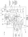
- the domestic energy center 500 shown has a ventilation device 12 which has a first air line 14 from an outside air connection 16 to a supply air connection 18 and a second air line 20 from an exhaust air connection 22 to an exhaust air connection 24.
- the outside air connection 16 and the exhaust air connection 24 are connected to the environment U of a living room 26 during operation, not the living room 26 itself.
- the supply air connection 18 is connected to the living room 26 both directly via a supply air line 15 and indirectly via a fuel cell unit 200.
- the exhaust air connection 22 is connected to the living room 26 via an exhaust air line 30.
- the home energy center 500 additionally has an electrolysis unit 300, which is integrated into the exhaust air line 30 of the home energy center 500 in such a way that the exhaust air ABL originating from the common room 26 is guided as a cooling and flushing volume flow via the electrolysis unit 300 before it can flow to the second air line 20 of the ventilation device 12.
- a hydrogen dryer 360 and/or a catalytic burner 350 are optionally connected downstream of the electrolysis unit 300.
- the optional catalytic burner 350 is used for the catalytic combustion of hydrogen from a hydrogen tank (not shown) and thus for providing thermal energy for hot water and heating energy.
- the catalytic burner 350 is integrated into the exhaust air line 30 of the house energy center 500 in such a way that the process air required for the H2 combustion is taken from the cooling and flushing volume flow, that the exhaust air ABL originating from the common room 26 is guided as a cooling and flushing volume flow over the catalytic burner 350 and that the process air is fed back to the cooling and flushing volume flow after combustion, preferably in the mixing zone 370.
- a mixing zone 370 Downstream of the catalytic burner 350 in the exhaust air line 30 is a mixing zone 370 in which a hydrogen-containing purge gas originating from the fuel cell unit 200 and/or the electrolysis unit 300 can be mixed with the cooling and flushing volume flow and discharged from the house energy center as exhaust air FOL in the exhaust air line 30.
- a purge gas can be obtained, for example, by means of a purge arrangement (not shown) for flushing the fuel cell unit 200 on its anode side and the electrolysis unit 300 on its cathode side.
- a storage battery exhaust air connection 350 is visible, via which a storage battery 400 assigned to the house energy center 500 and included here is fed into the exhaust air line 30 of the house energy center 500.
- the exhaust air ABL originating from the common room 26 is thus also guided via the storage battery 400.
- undesirable gas emissions, in particular H2 which is generated when the storage battery unit is overloaded, can also be discharged from the storage battery 400.
- the home energy center 500 has power electronic components 450, which are also integrated into the exhaust air line 30 of the home energy center 500.
- the exhaust air ABL originating from the common room 26 is therefore also guided via the power electronic components 450.
- the power electronic components 450 can be used to charge the storage battery 400, for example, using solar power from a photovoltaic system (not shown), supply the household with 230 VAC and/or connect the fuel cell unit and/or the electrolysis unit to the 48 VDC node, to which the storage battery unit 400 is also connected.
- an ultra-short-term storage device (supercap) can also be integrated here, which is also connected to the 48 VDC node.
- the ventilation unit 12, the fuel cell unit 200, the electrolysis unit 300, the power electronic components solar charge controller 450, the storage battery 400, the catalytic burner 350 and the hydrogen dryer 360 are housed in a common housing 550, which makes the home energy center 500 particularly compact.
- Both the first ventilation line 14 of the ventilation device 12 and the second ventilation line 20 of the ventilation device 12 are routed via a heat exchanger 34 of the ventilation device 12, so that a heat exchange takes place between the air flows routed via the two air lines 14 and 20.
- exhaust air ABL routed via the second air line 20 can transfer its heat to outside air AUL routed via the first air line 14, so that at least part of the thermal energy of the room air RL that would otherwise be dissipated with the exhaust air FOL can be recovered and returned to the living space 26.
- An outside air bypass 14' with a bypass flap 60 is also provided on the ventilation unit 12 in order to bypass the heat exchanger 34 of the ventilation unit 12 if necessary.
- This bypass flap 60 can be controlled in such a way that outside air AUL flowing in via the outside air connection 16 flows directly into the supply air line 15.
- the fuel cell unit 200 is connected on the inlet side via part of the supply air line 15 to the supply air connection 18 of the ventilation device 12 and is thus supplied with fresh and optionally preheated supply air ZUL, which is simultaneously required both for the reaction with the hydrogen in the fuel cell unit of the fuel cell unit 200 and as cooling air to dissipate the heat generated during the reaction.
- the fuel cell unit of the fuel cell unit 200 has proton exchange membranes (PEM membranes) to which the reaction air flow and cooling air flow are not supplied separately, but in one air flow. This air flow through the fuel cell unit 200 absorbs water generated as a result of the reaction in the fuel cell unit and is thus humidified.
- the warm and moist air flow emerging from the fuel cell unit 200 is fed wholly or partially to the supply air line 200 and/or the exhaust air line 30.
- the supply air ZUL exiting the ventilation device 12 is cooler and drier than the desired room air RL, i.e. if heat and moisture must be added to it, part or all of the air exiting the fuel cell unit 200 is fed to this supply air ZUL.
- the outlet of the fuel cell unit 200 is connected to the supply air line 15 via a first fuel cell outlet line 36.
- a non-return valve 38 is connected upstream of the fuel cell unit 200 on the inlet side.
- the air exiting from the fuel cell unit 200 is fed via a second fuel cell outlet line 40, controlled by a ventilation flap 42 arranged therein, to the exhaust air line 30 as exhaust air ABL' and thus returned to the ventilation device 12.
- reaction heat dissipated with the air exiting the fuel cell unit 200 is conducted with the exhaust air flow through the heat exchanger 34 of the ventilation device 12, so that this thermal energy can also be at least partially extracted from the exhaust air flow and fed into the supply air flow.
- the air flow exiting from the fuel cell unit 200 and which can be fed to the second air duct 20 of the ventilation device 12 as exhaust air ABL ⁇ is guided in such a way that it only mixes with the exhaust air ABL originating from a respective living room 26 after it has flowed through the electrolysis unit 300.
- controllable ventilation flap 42 can also be used to adjust how much of the supply air ZUL exiting the ventilation device 12 is fed directly to the living room 26 and how much of the air is fed to the fuel cell unit 200 and thus, if applicable, indirectly to the room air RL in the living room 26.
- the control of the home energy center 500 and in particular the ventilation flap 42 is carried out by the air temperature and the air humidity in the living room 26.
- an air humidity sensor 50 and an air temperature sensor 52 are arranged on the exhaust air connection 25.
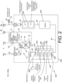
- the design of the home energy center 500 in Fig. 2 shows the integration of a liquid-cooled fuel cell unit 200.
- the main heat of the fuel cell unit 200 is released to a hot water tank 800 via a cooling circuit.
- the fuel cell unit 200 can be integrated into the same sub-room TR1 in which the electrolysis unit 300 is also integrated.
- the devices for the optional direct coupling of the fuel cell cooling air into the supply air of the living spaces in this design part of the cooling and flushing volume flow is used as fuel cell reaction air in the fuel cell cathode and the moist and heated exhaust air from the fuel cell cathode is then mixed with the cooling and flushing volume flow. Heat and moisture from the fuel cell unit 200 can thus be released into the supply air ZUL via the cooling and flushing volume flow and via the gas/gas heat exchanger 12.
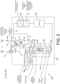
- Fig. 3 shows an embodiment of the home energy center 500 without connection to a KWL, as is often found when integrating into existing residential complexes, since central KWL systems are often not to be retrofitted there.
- the home energy center 500 here draws in outside air AUL via a fan and a filter as part of the ventilation unit 12 and optionally heats this outside air AUL via a gas/gas heat exchanger 34 and thus provides the cooling and flushing volume flow for the home energy center 5000.
- This cooling and flushing volume flow and thus also the ventilation components within the housing, in particular the fan, the flow channels and the gas/gas heat exchanger 34, can be made significantly smaller than in the embodiments of the Fig.1 and Fig.2 , in which the entire exhaust air ABL of the common room 26 is preferably used, and its dimensioning is based solely on the requirements of the safety/heating and process technology of the domestic energy center 500.
- An advantage of this design is also the more compact design when only one volume flow is present and passed through the housing 550.
- the air-cooled fuel cell unit 200 takes at least a portion of the cooling and flushing volume flow for the electrochemical reaction with the hydrogen and for cooling the fuel cell unit 200.
- This air flow through the fuel cell unit 200 absorbs water and heat generated as a result of the reaction in the fuel cell unit 200 and is thus humidified.
- the warm and moist air flow exiting the fuel cell unit 200 is mixed with the unused portion of the cooling and flushing volume flow and flows through the other system parts to dilute the escaping gases and to absorb heat.
- the heat released by all components within the housing to the cooling and flushing volume flow can be released to the hot water tank 800 via the optional heat exchanger 39, which can be coupled to the hot water tank 800 directly or via a heat pump.
- Fig. 4 shows an embodiment of the home energy center 500, similar to that of Fig.3 , in which there is no connection to a KWL and in which a liquid-cooled fuel cell unit 200 is integrated.
- the main heat of the fuel cell unit 200 is released to the heat storage unit (not shown) via a cooling circuit.
- the fuel cell unit 200 can be integrated into the same sub-space TR1 in which the electrolysis unit 300 is integrated.
- a smaller part of the cooling and flushing volume flow is conveyed as fuel cell reaction air into the fuel cell cathode and the moist and heated cathode exhaust air is mixed with the cooling and flushing volume flow.
- the heat released by all components within the housing 550 to the cooling and flushing volume flow can also be released to the hot water storage tank 800 via the optional heat exchanger, which can be coupled to the hot water storage tank 800 directly or via a heat pump.
- a home energy center 500 in Fig. 5 serves to provide a self-sufficient energy supply of electricity and/or heat to a residential building equipped with a KWL.
- the Home Energy Center 500 in Fig. 5 has a housing 550 which has an outside air connection 16 and an exhaust air connection 24. Also provided is a ventilation device 12 having a heat exchanger 34.
- the ventilation device 12 is connected to the outside air connection 16 in such a way that outside air AUL in a first air line 14 via the Heat exchanger 34, can flow into a supply air line 15 of the house energy center 500.
- the supply air line 15 runs at least partially within the housing 550.
- the home energy center 500 has a supply air connection 17 and an exhaust air connection 25 for connecting the home energy center 500 to at least one living room 26 to be centrally ventilated, such that an air flow flowing into the supply air line 15 of the home energy center 500 can first be supplied to the living room 26 as supply air ZUL.
- Home energy center 500 in Fig. 5 also has an exhaust air line 30 in which an air volume flow caused by the ventilation device 12 can be continued within the housing 50. Exhaust air ABL originating from the living room 26 can be continued in the exhaust air line 30 of the house energy center 500.
- Home Energy Center 500 in Fig. 5 further comprises a fuel cell unit 200, which is arranged within the housing 550 and is integrated into the exhaust air line 30 in such a way that undesirable gas released in the fuel cell unit 200 can be diluted by the air volume flow and discharged together with waste heat from the fuel cell unit 200. Also part of the home energy center 500 is a storage battery unit 450, which is arranged in an external housing 555 and is integrated into the exhaust air line 30 in such a way that undesirable gas released in the storage battery unit 450 can be diluted by the air volume flow and discharged together with waste heat from the storage battery unit 450.
- Home Energy Center 500 in Fig. 5 is equipped with a second air line 20 which is connected to the exhaust air line 30, wherein the second air line 20 of the ventilation device 12 is thermally coupled to the first air line 14 via the heat exchanger 34 of the ventilation device 12, so that exhaust air ABL led to the outside via the second air line 20 can release at least part of the thermal energy contained in it to the first air line 14 via the heat exchanger 34 of the ventilation device 12 and at the same time the undesirable gases diluted by the air volume flow can be discharged with the air volume flow via the outside air connection 16, so that the formation of explosive gas mixtures in the domestic energy center is avoided and it can be operated safely.
- FIG. 5 shows similar to the embodiment of the Fig. 1 a domestic energy center 500 with exclusively air-cooled fuel cell unit 200 and connected to a common room 26 for the purpose of controlled living space ventilation.
- outside air AUL from the environment U enters the house energy center 500 as air volume flow L via the outside air connection 16 of the housing 550. This is effected by a fan of the ventilation device 12.
- the air volume flow L then flows via the first air line 14 via the heat exchanger 34 into the supply air line 15 and from there via the supply air connection 17 into the living room 26.
- a portion L' of the air volume flow L is supplied in parallel flow to the fuel cell unit 200 (in Fig. 5 example downwards) This portion L' is sucked in by a fan 201 of the fuel cell unit 200.
- the portion L' mixes via the slightly opened control flap 43 with the air volume flow L, which flows from there via the supply air connection 17 into the living room 26.
- the air volume flow L (as exhaust air ABL) flows via the exhaust air connection 25 into the exhaust air line 30 of the house energy center 500 and in the further course (in Fig. 5 example downwards) to an additional fan 112.
- the additional fan 112 and a power electronics 450 are arranged in a sub-chamber TR2.
- the air volume flow L flows via the exhaust air line 30 to the exhaust air connection 350, via which the storage battery 400 assigned to the home energy center 500 and arranged in the external housing is integrated into the exhaust air line 30 of the home energy center 500.
- the air volume flow L flows back into the housing 550 via the exhaust air connection 350'.
- the air volume flow L flows to the catalytic burner 350 in the subspace TR3 (in Fig. 5 example at the bottom) and further course to the electrolysis unit 300 in sub-chamber TR4. Accordingly, the sub-chambers TR2, TR3, TR4 are flowed through serially. Finally, the air volume flow L flows past a hydrogen sensor 59 and from there into the second air line 20 and through the heat exchanger 35 to the exhaust air connection 24 in order to pass through this as exhaust air to the environment U.
Landscapes
- Engineering & Computer Science (AREA)
- Chemical & Material Sciences (AREA)
- Electrochemistry (AREA)
- Chemical Kinetics & Catalysis (AREA)
- General Chemical & Material Sciences (AREA)
- Manufacturing & Machinery (AREA)
- Life Sciences & Earth Sciences (AREA)
- Sustainable Development (AREA)
- Sustainable Energy (AREA)
- Business, Economics & Management (AREA)
- Physics & Mathematics (AREA)
- Combustion & Propulsion (AREA)
- Health & Medical Sciences (AREA)
- Economics (AREA)
- General Engineering & Computer Science (AREA)
- Mechanical Engineering (AREA)
- Thermal Sciences (AREA)
- Primary Health Care (AREA)
- General Business, Economics & Management (AREA)
- Water Supply & Treatment (AREA)
- General Health & Medical Sciences (AREA)
- Human Resources & Organizations (AREA)
- Marketing (AREA)
- Power Engineering (AREA)
- Strategic Management (AREA)
- Tourism & Hospitality (AREA)
- Public Health (AREA)
- General Physics & Mathematics (AREA)
- Theoretical Computer Science (AREA)
- Inorganic Chemistry (AREA)
- Materials Engineering (AREA)
- Metallurgy (AREA)
- Organic Chemistry (AREA)
- Fuel Cell (AREA)
Applications Claiming Priority (2)
| Application Number | Priority Date | Filing Date | Title |
|---|---|---|---|
| DE102015120454 | 2015-11-25 | ||
| PCT/EP2016/078691 WO2017089469A1 (de) | 2015-11-25 | 2016-11-24 | Hausenergiezentrale und verfahren zum betreiben einer hausenergiezentrale |
Publications (3)
| Publication Number | Publication Date |
|---|---|
| EP3380792A1 EP3380792A1 (de) | 2018-10-03 |
| EP3380792C0 EP3380792C0 (de) | 2024-10-23 |
| EP3380792B1 true EP3380792B1 (de) | 2024-10-23 |
Family
ID=57391990
Family Applications (1)
| Application Number | Title | Priority Date | Filing Date |
|---|---|---|---|
| EP16800990.0A Active EP3380792B1 (de) | 2015-11-25 | 2016-11-24 | Hausenergiezentrale und verfahren zum betreiben einer hausenergiezentrale |
Country Status (6)
| Country | Link |
|---|---|
| US (1) | US11120514B2 (pl) |
| EP (1) | EP3380792B1 (pl) |
| CN (1) | CN108474565B (pl) |
| ES (1) | ES3002182T3 (pl) |
| PL (1) | PL3380792T3 (pl) |
| WO (1) | WO2017089469A1 (pl) |
Families Citing this family (26)
| Publication number | Priority date | Publication date | Assignee | Title |
|---|---|---|---|---|
| DE102018111564A1 (de) * | 2018-05-15 | 2019-11-21 | Schuster Energieversorgungssysteme Gmbh & Co. Kg | Vermeidung der Belüftung von Schränken mit Batterien |
| DE102018133201A1 (de) * | 2018-12-20 | 2020-06-25 | Hps Home Power Solutions Gmbh | Spülsystem und dessen Verwendung in einem Energiesystem |
| DE102018133198A1 (de) | 2018-12-20 | 2020-06-25 | Hps Home Power Solutions Gmbh | Energiesystem und Verfahren zur Druckanpassung in einem Energiesystem |
| DE102018133203A1 (de) | 2018-12-20 | 2020-06-25 | Hps Home Power Solutions Gmbh | Spülsystem und Verfahren zu dessen Überwachung |
| DE102018133199A1 (de) * | 2018-12-20 | 2020-06-25 | Hps Home Power Solutions Gmbh | Verfahren zum Einspeichern eines Mediums in eine Druckspeichereinrichtung |
| DE102018133206B3 (de) | 2018-12-20 | 2020-03-26 | Hps Home Power Solutions Gmbh | Energiesystem und Verfahren zur Leitungsdrucküberwachung |
| DE102018133194A1 (de) | 2018-12-20 | 2020-06-25 | Hps Home Power Solutions Gmbh | Lüftungssystem und Verfahren zu dessen Betrieb |
| DE202019102516U1 (de) | 2019-05-06 | 2019-05-15 | Hps Home Power Solutions Gmbh | Energiesystem |
| NL2025467B1 (nl) * | 2020-03-18 | 2021-10-19 | Lucky Beheer B V | Warmwaterinstallatie en werkwijze voor verwarmen van water |
| DE112022003401T5 (de) | 2021-07-05 | 2024-04-18 | Blue World Technologies Holding ApS | Elektrisches Kraftfahrzeug mit einem Brennstoffzeliensystem und Verfahren zur Brandrisikobegrenzung |
| US20230175706A1 (en) * | 2021-12-07 | 2023-06-08 | Ohmium International, Inc. | Integrated systems for generating thermal energy and hydrogen |
| DE102022109043A1 (de) | 2022-04-13 | 2023-10-19 | Hps Home Power Solutions Ag | Vorrichtung zur Aufbereitung einer Elektrolytflüssigkeit |
| DE102022113558A1 (de) | 2022-05-30 | 2023-11-30 | Hps Home Power Solutions Ag | Vorrichtung zum Trocknen eines Gasstroms |
| DE102022114038A1 (de) | 2022-06-02 | 2023-12-07 | Hps Home Power Solutions Ag | Energiesystem |
| GB2620986B (en) * | 2022-07-29 | 2024-07-24 | Octopus Energy Heating Ltd | Hot water supply system |
| DE102022130105A1 (de) | 2022-08-03 | 2024-02-08 | Hps Home Power Solutions Ag | Speichervorrichtung zum Speichern von Gas |
| EP4317761A1 (de) | 2022-08-03 | 2024-02-07 | HPS Home Power Solutions AG | Speichervorrichtung zum speichern von gas |
| DE102022131679A1 (de) | 2022-11-30 | 2024-06-06 | Hps Home Power Solutions Ag | Energiesystem |
| DE102022131682B3 (de) | 2022-11-30 | 2023-08-10 | Hps Home Power Solutions Ag | Energiesystem sowie Verfahren zur Überwachung eines Energiesystems auf Dichtigkeit und/oder Störungen. |
| DE102022131680A1 (de) | 2022-11-30 | 2024-06-06 | Hps Home Power Solutions Ag | Energiesystem |
| DE102022131861A1 (de) | 2022-12-01 | 2024-06-06 | Hps Home Power Solutions Ag | Kondensatablaufeinrichtung und Verfahren zu deren Betrieb |
| DE102022133761A1 (de) * | 2022-12-16 | 2024-06-27 | HYTING GmbH | Lüftungsheizvorrichtung zum Erwärmen eines Luftstroms und Verfahren zum Betreiben einer Lüftungsheizvorrichtung |
| DE102023113240A1 (de) | 2023-05-22 | 2024-11-28 | Hps Home Power Solutions Ag | Energiesystem |
| DE102023204856A1 (de) * | 2023-05-25 | 2024-11-28 | Robert Bosch Gesellschaft mit beschränkter Haftung | Fluidversorgungsvorrichtung und elektrochemisches System |
| DE102023119435A1 (de) | 2023-07-24 | 2025-01-30 | Hps Home Power Solutions Ag | Vermeidung einer explosionsfähigen Atmosphäre in einem Energiesystem |
| EP4570964A1 (de) | 2023-12-13 | 2025-06-18 | HPS Home Power Solutions AG | Spülvorrichtung zum zwischenspeichern eines gasförmigen mediums aus einem spülvorgang |
Citations (1)
| Publication number | Priority date | Publication date | Assignee | Title |
|---|---|---|---|---|
| WO2010075602A1 (de) * | 2008-12-30 | 2010-07-08 | Fronius International Gmbh | Verfahren und vorrichtung zum austragen verbrauchter und zum teil explosionsfähiger betriebsmedien einer brennstoffzelle |
Family Cites Families (11)
| Publication number | Priority date | Publication date | Assignee | Title |
|---|---|---|---|---|
| US5980726A (en) * | 1998-05-05 | 1999-11-09 | Proton Energy Systems | Hydrogen electrochemical system environment |
| US6627340B1 (en) * | 1999-11-06 | 2003-09-30 | Energy Conversion Devices, Inc. | Fuel cell hydrogen supply systems using secondary fuel to release stored hydrogen |
| US6401463B1 (en) * | 2000-11-29 | 2002-06-11 | Marconi Communications, Inc. | Cooling and heating system for an equipment enclosure using a vortex tube |
| CN1212492C (zh) * | 2001-11-19 | 2005-07-27 | 乐金电子(天津)电器有限公司 | 具换气功能的空调器 |
| DE20307317U1 (de) * | 2003-05-09 | 2004-09-16 | Viessmann Werke Gmbh & Co Kg | Brennstoffzellen-Heizgerät |
| JP4432369B2 (ja) * | 2003-05-30 | 2010-03-17 | ダイキン工業株式会社 | 調湿装置 |
| CN101893301A (zh) * | 2010-07-12 | 2010-11-24 | 孟翔鸣 | 移动通信基站排热控温节能系统 |
| DE102011076650A1 (de) * | 2011-02-25 | 2012-10-04 | Heliocentris Energiesysteme Gmbh | Lüftungs- und Heizsystem |
| JP5763484B2 (ja) * | 2011-09-15 | 2015-08-12 | 本田技研工業株式会社 | 燃料電池システム |
| CN102340045B (zh) * | 2011-09-28 | 2016-05-11 | 奇瑞汽车股份有限公司 | 一种动力电池冷却循环系统 |
| EP2869377A1 (en) * | 2013-10-29 | 2015-05-06 | Total Marketing Services | Power generation system |
-
2016
- 2016-11-24 PL PL16800990.0T patent/PL3380792T3/pl unknown
- 2016-11-24 ES ES16800990T patent/ES3002182T3/es active Active
- 2016-11-24 WO PCT/EP2016/078691 patent/WO2017089469A1/de not_active Ceased
- 2016-11-24 EP EP16800990.0A patent/EP3380792B1/de active Active
- 2016-11-24 US US15/777,973 patent/US11120514B2/en active Active
- 2016-11-24 CN CN201680079724.7A patent/CN108474565B/zh active Active
Patent Citations (1)
| Publication number | Priority date | Publication date | Assignee | Title |
|---|---|---|---|---|
| WO2010075602A1 (de) * | 2008-12-30 | 2010-07-08 | Fronius International Gmbh | Verfahren und vorrichtung zum austragen verbrauchter und zum teil explosionsfähiger betriebsmedien einer brennstoffzelle |
Also Published As
| Publication number | Publication date |
|---|---|
| CN108474565A (zh) | 2018-08-31 |
| US20190385245A1 (en) | 2019-12-19 |
| EP3380792A1 (de) | 2018-10-03 |
| EP3380792C0 (de) | 2024-10-23 |
| ES3002182T3 (en) | 2025-03-06 |
| US11120514B2 (en) | 2021-09-14 |
| PL3380792T3 (pl) | 2025-03-31 |
| WO2017089469A1 (de) | 2017-06-01 |
| CN108474565B (zh) | 2022-02-11 |
Similar Documents
| Publication | Publication Date | Title |
|---|---|---|
| EP3380792B1 (de) | Hausenergiezentrale und verfahren zum betreiben einer hausenergiezentrale | |
| DE112011102786B4 (de) | Lufteinnahmevorrichtung für luftgekühlte Brennstoffzellen und damit durchgeführtes Verfahren | |
| DE102005012120A1 (de) | Luftfahrzeug mit einer Brennstoffzelle | |
| DE102010061628A1 (de) | System und Verfahren zur Leistungssteigerung von Gasturbinen | |
| DE112023001192T5 (de) | Dampfinjektionsmodul und Fahrzeugwärmemanagement mit diesem Modul | |
| EP2371023B1 (de) | Verfahren und vorrichtung zum austragen verbrauchter und zum teil explosionsfähiger betriebsmedien einer brennstoffzelle | |
| DE19706584C2 (de) | Hochtemperaturbrennstoffzellen mit Erwärmung des Reaktionsgases | |
| EP2678611B1 (de) | Lüftungs- und heizsystem | |
| DE102015117055B4 (de) | Stapelgehäuse-Belüftung, Brennstoffzellensystem sowie Fahrzeug | |
| DE102022131682B3 (de) | Energiesystem sowie Verfahren zur Überwachung eines Energiesystems auf Dichtigkeit und/oder Störungen. | |
| DE112016005853B4 (de) | Gaszu- und -abführsystem | |
| DE102010047523A1 (de) | Brennstoffzellensystem mit wenigstens einer Brennstoffzelle | |
| EP4379876A2 (de) | Energiesystem | |
| DE112013005350T5 (de) | Energieerzeugungssystem und Verfahren zum Kühlen von Brennstoffzellenabgas in Einem Energieerzeugungssystem | |
| DE102014018444A1 (de) | Brennstoffzellensystem und Gas/Gas-Befeuchter | |
| DE102014103554B4 (de) | Verfahren und Vorrichtung zur Gewinnung von Stickstoff aus Luft | |
| DE10324386B4 (de) | Brennstoffzellensystem | |
| DE102012011326A1 (de) | Brennstoffzellensystem | |
| DE102020105044B3 (de) | Dezentrale Vorrichtung zur Klimatisierung und Belüftung von einzelnen Innenräumen und System zur Klimatisierung von Innenräumen | |
| DE102014017868A1 (de) | System mit Vorrichtung zur Trocknung von Gas für Batteriegehäuse | |
| EP4095443A1 (de) | Energiewandlungsvorrichtung mit einer brennstoffzelleneinheit | |
| DE202021102823U1 (de) | Energiewandlungsvorrichtung mit einer Brennstoffzelleneinheit | |
| DE202024102388U1 (de) | Trockenanlage | |
| DE102017215255A1 (de) | Verfahren zur Bestimmung der Temperatur eines Kathodenbetriebsgases am Eingang eines Befeuchtermoduls eines Brennstoffzellensystems, Brennstoffzellensystem und Fahrzeug | |
| DE102024200823A1 (de) | Vorrichtung für ein Batteriegehäuse |
Legal Events
| Date | Code | Title | Description |
|---|---|---|---|
| STAA | Information on the status of an ep patent application or granted ep patent |
Free format text: STATUS: UNKNOWN |
|
| STAA | Information on the status of an ep patent application or granted ep patent |
Free format text: STATUS: THE INTERNATIONAL PUBLICATION HAS BEEN MADE |
|
| PUAI | Public reference made under article 153(3) epc to a published international application that has entered the european phase |
Free format text: ORIGINAL CODE: 0009012 |
|
| STAA | Information on the status of an ep patent application or granted ep patent |
Free format text: STATUS: REQUEST FOR EXAMINATION WAS MADE |
|
| 17P | Request for examination filed |
Effective date: 20180625 |
|
| AK | Designated contracting states |
Kind code of ref document: A1 Designated state(s): AL AT BE BG CH CY CZ DE DK EE ES FI FR GB GR HR HU IE IS IT LI LT LU LV MC MK MT NL NO PL PT RO RS SE SI SK SM TR |
|
| AX | Request for extension of the european patent |
Extension state: BA ME |
|
| RIN1 | Information on inventor provided before grant (corrected) |
Inventor name: BENZ, UWE Inventor name: RADUE, DIRK Inventor name: SCHROEDER, KEVIN Inventor name: ABUL-ELLA, ZEYAD Inventor name: HIERL, ANDREAS Inventor name: SCHNEIDER, GUNNAR |
|
| RIN1 | Information on inventor provided before grant (corrected) |
Inventor name: SCHROEDER, KEVIN Inventor name: RADUE, DIRK Inventor name: BENZ, UWE Inventor name: ABUL-ELLA, ZEYAD Inventor name: SCHNEIDER, GUNNAR Inventor name: HIERL, ANDREAS |
|
| DAV | Request for validation of the european patent (deleted) | ||
| DAX | Request for extension of the european patent (deleted) | ||
| STAA | Information on the status of an ep patent application or granted ep patent |
Free format text: STATUS: EXAMINATION IS IN PROGRESS |
|
| 17Q | First examination report despatched |
Effective date: 20201022 |
|
| GRAP | Despatch of communication of intention to grant a patent |
Free format text: ORIGINAL CODE: EPIDOSNIGR1 |
|
| STAA | Information on the status of an ep patent application or granted ep patent |
Free format text: STATUS: GRANT OF PATENT IS INTENDED |
|
| RIC1 | Information provided on ipc code assigned before grant |
Ipc: H01M 10/613 20140101ALI20240429BHEP Ipc: F24D 101/30 20220101ALI20240429BHEP Ipc: H01M 10/66 20140101ALI20240429BHEP Ipc: F24D 103/13 20220101ALI20240429BHEP Ipc: F24D 18/00 20220101ALI20240429BHEP Ipc: H02J 3/32 20060101ALI20240429BHEP Ipc: H01M 16/00 20060101ALI20240429BHEP Ipc: H01M 10/627 20140101ALI20240429BHEP Ipc: H01M 8/247 20160101ALI20240429BHEP Ipc: H01M 8/0662 20160101ALI20240429BHEP Ipc: H01M 8/04014 20160101ALI20240429BHEP Ipc: G06Q 50/06 20120101ALI20240429BHEP Ipc: C25B 1/04 20060101ALI20240429BHEP Ipc: F24D 5/02 20060101AFI20240429BHEP |
|
| INTG | Intention to grant announced |
Effective date: 20240516 |
|
| GRAS | Grant fee paid |
Free format text: ORIGINAL CODE: EPIDOSNIGR3 |
|
| GRAA | (expected) grant |
Free format text: ORIGINAL CODE: 0009210 |
|
| STAA | Information on the status of an ep patent application or granted ep patent |
Free format text: STATUS: THE PATENT HAS BEEN GRANTED |
|
| AK | Designated contracting states |
Kind code of ref document: B1 Designated state(s): AL AT BE BG CH CY CZ DE DK EE ES FI FR GB GR HR HU IE IS IT LI LT LU LV MC MK MT NL NO PL PT RO RS SE SI SK SM TR |
|
| REG | Reference to a national code |
Ref country code: GB Ref legal event code: FG4D Free format text: NOT ENGLISH |
|
| RIN1 | Information on inventor provided before grant (corrected) |
Inventor name: ABUL-ELLA, ZEYAD Inventor name: SCHROEDER, KEVIN Inventor name: BENZ, UWE Inventor name: SCHNEIDER, GUNNAR Inventor name: RADUE, DIRK Inventor name: HIERL, ANDREAS |
|
| REG | Reference to a national code |
Ref country code: CH Ref legal event code: EP |
|
| REG | Reference to a national code |
Ref country code: DE Ref legal event code: R096 Ref document number: 502016016761 Country of ref document: DE |
|
| REG | Reference to a national code |
Ref country code: IE Ref legal event code: FG4D Free format text: LANGUAGE OF EP DOCUMENT: GERMAN |
|
| RAP2 | Party data changed (patent owner data changed or rights of a patent transferred) |
Owner name: HPS HOME POWER SOLUTIONS AG |
|
| U01 | Request for unitary effect filed |
Effective date: 20241122 |
|
| U07 | Unitary effect registered |
Designated state(s): AT BE BG DE DK EE FI FR IT LT LU LV MT NL PT RO SE SI Effective date: 20241129 |
|
| PGFP | Annual fee paid to national office [announced via postgrant information from national office to epo] |
Ref country code: GB Payment date: 20241204 Year of fee payment: 9 |
|
| REG | Reference to a national code |
Ref country code: ES Ref legal event code: FG2A Ref document number: 3002182 Country of ref document: ES Kind code of ref document: T3 Effective date: 20250306 |
|
| PG25 | Lapsed in a contracting state [announced via postgrant information from national office to epo] |
Ref country code: IS Free format text: LAPSE BECAUSE OF FAILURE TO SUBMIT A TRANSLATION OF THE DESCRIPTION OR TO PAY THE FEE WITHIN THE PRESCRIBED TIME-LIMIT Effective date: 20250223 Ref country code: HR Free format text: LAPSE BECAUSE OF FAILURE TO SUBMIT A TRANSLATION OF THE DESCRIPTION OR TO PAY THE FEE WITHIN THE PRESCRIBED TIME-LIMIT Effective date: 20241023 |
|
| PGFP | Annual fee paid to national office [announced via postgrant information from national office to epo] |
Ref country code: ES Payment date: 20250109 Year of fee payment: 9 |
|
| PG25 | Lapsed in a contracting state [announced via postgrant information from national office to epo] |
Ref country code: NO Free format text: LAPSE BECAUSE OF FAILURE TO SUBMIT A TRANSLATION OF THE DESCRIPTION OR TO PAY THE FEE WITHIN THE PRESCRIBED TIME-LIMIT Effective date: 20250123 |
|
| PG25 | Lapsed in a contracting state [announced via postgrant information from national office to epo] |
Ref country code: GR Free format text: LAPSE BECAUSE OF FAILURE TO SUBMIT A TRANSLATION OF THE DESCRIPTION OR TO PAY THE FEE WITHIN THE PRESCRIBED TIME-LIMIT Effective date: 20250124 |
|
| PGFP | Annual fee paid to national office [announced via postgrant information from national office to epo] |
Ref country code: CH Payment date: 20250109 Year of fee payment: 9 |
|
| PGFP | Annual fee paid to national office [announced via postgrant information from national office to epo] |
Ref country code: PL Payment date: 20241104 Year of fee payment: 9 |
|
| PG25 | Lapsed in a contracting state [announced via postgrant information from national office to epo] |
Ref country code: RS Free format text: LAPSE BECAUSE OF FAILURE TO SUBMIT A TRANSLATION OF THE DESCRIPTION OR TO PAY THE FEE WITHIN THE PRESCRIBED TIME-LIMIT Effective date: 20250123 |
|
| U21 | Renewal fee for the european patent with unitary effect paid with additional fee |
Year of fee payment: 9 Effective date: 20250409 |
|
| PG25 | Lapsed in a contracting state [announced via postgrant information from national office to epo] |
Ref country code: SM Free format text: LAPSE BECAUSE OF FAILURE TO SUBMIT A TRANSLATION OF THE DESCRIPTION OR TO PAY THE FEE WITHIN THE PRESCRIBED TIME-LIMIT Effective date: 20241023 |
|
| PG25 | Lapsed in a contracting state [announced via postgrant information from national office to epo] |
Ref country code: MC Free format text: LAPSE BECAUSE OF FAILURE TO SUBMIT A TRANSLATION OF THE DESCRIPTION OR TO PAY THE FEE WITHIN THE PRESCRIBED TIME-LIMIT Effective date: 20241023 |
|
| PG25 | Lapsed in a contracting state [announced via postgrant information from national office to epo] |
Ref country code: SK Free format text: LAPSE BECAUSE OF FAILURE TO SUBMIT A TRANSLATION OF THE DESCRIPTION OR TO PAY THE FEE WITHIN THE PRESCRIBED TIME-LIMIT Effective date: 20241023 |
|
| PG25 | Lapsed in a contracting state [announced via postgrant information from national office to epo] |
Ref country code: CZ Free format text: LAPSE BECAUSE OF FAILURE TO SUBMIT A TRANSLATION OF THE DESCRIPTION OR TO PAY THE FEE WITHIN THE PRESCRIBED TIME-LIMIT Effective date: 20241023 |
|
| PLBE | No opposition filed within time limit |
Free format text: ORIGINAL CODE: 0009261 |
|
| STAA | Information on the status of an ep patent application or granted ep patent |
Free format text: STATUS: NO OPPOSITION FILED WITHIN TIME LIMIT |
|
| 26N | No opposition filed |
Effective date: 20250724 |
|
| PG25 | Lapsed in a contracting state [announced via postgrant information from national office to epo] |
Ref country code: IE Free format text: LAPSE BECAUSE OF NON-PAYMENT OF DUE FEES Effective date: 20241124 |