EP3380211B1 - Filter cartridge for a vehicule oil filter and oil filter - Google Patents
Filter cartridge for a vehicule oil filter and oil filter Download PDFInfo
- Publication number
- EP3380211B1 EP3380211B1 EP16798089.5A EP16798089A EP3380211B1 EP 3380211 B1 EP3380211 B1 EP 3380211B1 EP 16798089 A EP16798089 A EP 16798089A EP 3380211 B1 EP3380211 B1 EP 3380211B1
- Authority
- EP
- European Patent Office
- Prior art keywords
- filter cartridge
- oil
- filter
- oil filter
- passage
- Prior art date
- Legal status (The legal status is an assumption and is not a legal conclusion. Google has not performed a legal analysis and makes no representation as to the accuracy of the status listed.)
- Active
Links
- 239000000463 material Substances 0.000 claims description 35
- 238000007789 sealing Methods 0.000 claims description 28
- 238000006073 displacement reaction Methods 0.000 claims description 11
- 238000009434 installation Methods 0.000 claims description 4
- 238000003825 pressing Methods 0.000 claims description 2
- 238000007599 discharging Methods 0.000 claims 1
- 238000002485 combustion reaction Methods 0.000 description 37
- 210000000078 claw Anatomy 0.000 description 10
- 238000013016 damping Methods 0.000 description 4
- 230000003993 interaction Effects 0.000 description 4
- 230000010355 oscillation Effects 0.000 description 3
- 230000009467 reduction Effects 0.000 description 3
- 206010021580 Inadequate lubrication Diseases 0.000 description 2
- 230000000694 effects Effects 0.000 description 2
- 239000000446 fuel Substances 0.000 description 2
- 238000004519 manufacturing process Methods 0.000 description 2
- 125000006850 spacer group Chemical group 0.000 description 2
- 230000003068 static effect Effects 0.000 description 2
- 239000010913 used oil Substances 0.000 description 2
- 239000000969 carrier Substances 0.000 description 1
- 230000008859 change Effects 0.000 description 1
- 230000001419 dependent effect Effects 0.000 description 1
- 238000011161 development Methods 0.000 description 1
- 230000018109 developmental process Effects 0.000 description 1
- 230000002996 emotional effect Effects 0.000 description 1
- 238000001914 filtration Methods 0.000 description 1
- 238000003780 insertion Methods 0.000 description 1
- 230000037431 insertion Effects 0.000 description 1
- 230000010354 integration Effects 0.000 description 1
- 239000000314 lubricant Substances 0.000 description 1
- 230000001050 lubricating effect Effects 0.000 description 1
- 238000005461 lubrication Methods 0.000 description 1
- 238000011045 prefiltration Methods 0.000 description 1
- 230000002028 premature Effects 0.000 description 1
- 230000000717 retained effect Effects 0.000 description 1
- 239000000565 sealant Substances 0.000 description 1
- 238000011144 upstream manufacturing Methods 0.000 description 1
Images


Classifications
-
- B—PERFORMING OPERATIONS; TRANSPORTING
- B01—PHYSICAL OR CHEMICAL PROCESSES OR APPARATUS IN GENERAL
- B01D—SEPARATION
- B01D35/00—Filtering devices having features not specifically covered by groups B01D24/00 - B01D33/00, or for applications not specifically covered by groups B01D24/00 - B01D33/00; Auxiliary devices for filtration; Filter housing constructions
- B01D35/14—Safety devices specially adapted for filtration; Devices for indicating clogging
- B01D35/147—Bypass or safety valves
-
- B—PERFORMING OPERATIONS; TRANSPORTING
- B01—PHYSICAL OR CHEMICAL PROCESSES OR APPARATUS IN GENERAL
- B01D—SEPARATION
- B01D27/00—Cartridge filters of the throw-away type
- B01D27/10—Safety devices, e.g. by-passes
- B01D27/103—Bypass or safety valves
-
- B—PERFORMING OPERATIONS; TRANSPORTING
- B01—PHYSICAL OR CHEMICAL PROCESSES OR APPARATUS IN GENERAL
- B01D—SEPARATION
- B01D29/00—Filters with filtering elements stationary during filtration, e.g. pressure or suction filters, not covered by groups B01D24/00 - B01D27/00; Filtering elements therefor
- B01D29/11—Filters with filtering elements stationary during filtration, e.g. pressure or suction filters, not covered by groups B01D24/00 - B01D27/00; Filtering elements therefor with bag, cage, hose, tube, sleeve or like filtering elements
- B01D29/114—Filters with filtering elements stationary during filtration, e.g. pressure or suction filters, not covered by groups B01D24/00 - B01D27/00; Filtering elements therefor with bag, cage, hose, tube, sleeve or like filtering elements arranged for inward flow filtration
-
- B—PERFORMING OPERATIONS; TRANSPORTING
- B01—PHYSICAL OR CHEMICAL PROCESSES OR APPARATUS IN GENERAL
- B01D—SEPARATION
- B01D29/00—Filters with filtering elements stationary during filtration, e.g. pressure or suction filters, not covered by groups B01D24/00 - B01D27/00; Filtering elements therefor
- B01D29/96—Filters with filtering elements stationary during filtration, e.g. pressure or suction filters, not covered by groups B01D24/00 - B01D27/00; Filtering elements therefor in which the filtering elements are moved between filtering operations; Particular measures for removing or replacing the filtering elements; Transport systems for filters
-
- B—PERFORMING OPERATIONS; TRANSPORTING
- B01—PHYSICAL OR CHEMICAL PROCESSES OR APPARATUS IN GENERAL
- B01D—SEPARATION
- B01D35/00—Filtering devices having features not specifically covered by groups B01D24/00 - B01D33/00, or for applications not specifically covered by groups B01D24/00 - B01D33/00; Auxiliary devices for filtration; Filter housing constructions
- B01D35/005—Filters specially adapted for use in internal-combustion engine lubrication or fuel systems
-
- B—PERFORMING OPERATIONS; TRANSPORTING
- B01—PHYSICAL OR CHEMICAL PROCESSES OR APPARATUS IN GENERAL
- B01D—SEPARATION
- B01D35/00—Filtering devices having features not specifically covered by groups B01D24/00 - B01D33/00, or for applications not specifically covered by groups B01D24/00 - B01D33/00; Auxiliary devices for filtration; Filter housing constructions
- B01D35/14—Safety devices specially adapted for filtration; Devices for indicating clogging
- B01D35/153—Anti-leakage or anti-return valves
-
- B—PERFORMING OPERATIONS; TRANSPORTING
- B01—PHYSICAL OR CHEMICAL PROCESSES OR APPARATUS IN GENERAL
- B01D—SEPARATION
- B01D35/00—Filtering devices having features not specifically covered by groups B01D24/00 - B01D33/00, or for applications not specifically covered by groups B01D24/00 - B01D33/00; Auxiliary devices for filtration; Filter housing constructions
- B01D35/16—Cleaning-out devices, e.g. for removing the cake from the filter casing or for evacuating the last remnants of liquid
-
- B—PERFORMING OPERATIONS; TRANSPORTING
- B01—PHYSICAL OR CHEMICAL PROCESSES OR APPARATUS IN GENERAL
- B01D—SEPARATION
- B01D2201/00—Details relating to filtering apparatus
- B01D2201/16—Valves
- B01D2201/167—Single-way valves
-
- B—PERFORMING OPERATIONS; TRANSPORTING
- B01—PHYSICAL OR CHEMICAL PROCESSES OR APPARATUS IN GENERAL
- B01D—SEPARATION
- B01D2201/00—Details relating to filtering apparatus
- B01D2201/29—Filter cartridge constructions
- B01D2201/291—End caps
-
- B—PERFORMING OPERATIONS; TRANSPORTING
- B01—PHYSICAL OR CHEMICAL PROCESSES OR APPARATUS IN GENERAL
- B01D—SEPARATION
- B01D2201/00—Details relating to filtering apparatus
- B01D2201/30—Filter housing constructions
- B01D2201/301—Details of removable closures, lids, caps, filter heads
- B01D2201/305—Snap, latch or clip connecting means
-
- B—PERFORMING OPERATIONS; TRANSPORTING
- B01—PHYSICAL OR CHEMICAL PROCESSES OR APPARATUS IN GENERAL
- B01D—SEPARATION
- B01D2201/00—Details relating to filtering apparatus
- B01D2201/34—Seals or gaskets for filtering elements
- B01D2201/347—Radial sealings
-
- B—PERFORMING OPERATIONS; TRANSPORTING
- B01—PHYSICAL OR CHEMICAL PROCESSES OR APPARATUS IN GENERAL
- B01D—SEPARATION
- B01D2201/00—Details relating to filtering apparatus
- B01D2201/40—Special measures for connecting different parts of the filter
- B01D2201/4084—Snap or Seeger ring connecting means
Definitions
- the invention relates to an oil filter with an oil filter housing in which a filter cartridge is arranged.
- the invention also relates to a filter cartridge for insertion into the oil filter housing of the oil filter of a motor vehicle.
- the filter cartridge has a channel for filtered oil, which is at least partially surrounded in the radial direction by a filter material of the filter cartridge.
- the filter cartridge has the closure element which can be displaced in the axial direction of the filter cartridge relative to the first end plate of the filter cartridge.
- the drainage channel which is provided for draining the oil from the receiving area of the oil filter housing for the filter cartridge, can be closed by means of the closure element.
- the inlet of the outlet channel can be released by moving the filter cartridge into the dismantling position of the filter cartridge. In the dismantling position, the filter cartridge is moved from the first position into a direction opposite to the second position. Accordingly, a service valve is provided by the closure element in cooperation with the drainage channel. When the service valve is open and the inlet of the drain channel is released, it can be ensured that all the used oil is drained from the internal combustion engine when the oil is changed. In this way, the filter cartridge can be changed without the oil being carried over.
- the provision of the check valve is particularly simple; In the present case, an actuating element which is susceptible to wear and which is movable relative to the filter cartridge for opening the check valve can be dispensed with. Rather, the movement of the entire filter cartridge in the axial direction leads to the opening of the check valve.
- the check valve is thus provided by a few components and with a particularly low complexity of the oil filter.
- the closure element is correspondingly spaced from the drainage channel.
- the filter cartridge can be held in the dismantling position on a cover element of the oil filter housing.
- claws or similar holding elements can be provided on the filter cartridge, which can interact with claws or similar holding elements provided on the side of the cover element.
- the length of the claws of the filter cartridge and the cover element is dimensioned such that the axial displaceability of the filter cartridge from the first position into the second position and from the second position into the third position is guaranteed.
- the function of the bypass valve or pressure relief valve can be provided in particular by the provision of seals pressed in the axial direction (that is, in the axial direction of the filter cartridge) against a corresponding contact surface.
- Such axial seals ensure a particularly low-wear, reliable and functionally safe seal when the valve is closed.
- the sleeve element can in particular be displaceable along a wall of the filter cartridge protruding from the first end plate of the filter cartridge.
- a wall of the filter cartridge protruding from the first end plate of the filter cartridge.
- a spring element for moving the closure element is preferably provided on the side of the filter cartridge. Accordingly, a spring element can be arranged on the filter cartridge, by means of which the closure element is acted upon by a spring force of the spring element in a position closing the inlet of the outlet channel. Then this spring element for moving the closure element is exchanged together with the filter cartridge when the filter cartridge is exchanged. Wear of the spring element can thus be taken into account particularly well.
- the closure element preferably has at least one sealing element which is provided for sealing the inlet of the outlet channel. Then this at least one sealing element acting in the axial direction of the filter cartridge is also replaced when the filter cartridge is replaced. Accordingly can thus also wear of the sealing element for sealing the inlet of the outlet channel can be taken into account in a simplified manner.
- Appropriate design of the spring elements of the oil filter can ensure that the filter cartridge does not vibrate during operation, i.e. that there are no rapidly changing movements in the axial direction of the filter cartridge.
- defined intermediate stops are preferably provided in the respective positions of the filter cartridge.
- damping volumes with passage openings or bores acting as throttles can be provided on the side of the filter cartridge and / or on the side of the oil filter housing. This also serves to avoid axial oscillation of the filter cartridge.
- the oil filter housing preferably has a tubular receptacle in which a first region of the channel of the filter cartridge that has the at least one passage opening is received when the filter cartridge is brought into the first position or into the second position.
- the first region of the channel rests against a closure device at least in the first position and in the second position of the filter cartridge.
- the closure device can be moved away from the tubular receptacle by moving the filter cartridge from the first position into the second position in order to open the inlet into the channel provided on the side of the oil filter housing.
- the pressure difference between the unfiltered oil and the filtered oil on the pure oil side of the filter material leads to the opening of the inlet into the channel provided on the side of the oil filter housing when the oil filter is in operation, i.e. when the internal combustion engine and the oil pump is running, as the filter cartridge moves the locking device.
- the oil filter housing preferably has a stop for a spring element which, when the filter cartridge is moved into a third position in which the filter cartridge is displaced even further in the axial direction of the filter cartridge relative to the second position, exerts a spring force acting counter to the displacement direction Filter cartridge exercises.
- a spring element By means of such a spring element, the spring force which has to be overcome in order to bring about the opening of the bypass valve can be applied in a targeted manner.
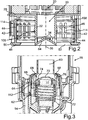
- Fig. 1 shows, in a sectional view, an oil filter 10 for a motor vehicle, which can in particular be a utility vehicle. However, one in Fig. 1 Likewise
- the filter cartridge 12 of the oil filter 10, shown in section, can also be used for an oil filter (not shown here) of a passenger vehicle.
- the oil filter 10 comprises an oil filter housing 14, which comprises a base body 16 and a cover 18 or a cover element. To change the filter cartridge 12, the cover 18 is dismantled or removed from the base body 16, as shown in FIG Fig. 1 is illustrated.
- the filter cartridge 12 has a channel 20 which is surrounded in the radial direction by a filter material 22.
- the filter material 22 can be designed, for example, as a folded filter.
- the channel 20 is tubular and has a plurality of recesses 24 in the area in which it is surrounded by the filter material 22.
- the oil filtered by means of the filter material 22 can reach the channel 20 via these recesses 24.
- the unfiltered oil accordingly passes in the radial direction, that is to say from the outside through the filter material 22 and thus reaches the channel 20.
- the channel 20 is in a region between a first, according to FIG Fig. 1 lower end plate 26 and a second, according to Fig. 1 upper end plate 28 surrounded by the filter material 22.
- the channel 20 is designed as a tubular connecting piece.
- a plurality of passage openings 34 is formed, the function of which will be explained in more detail below.
- the end 48 is tapered or stamped.
- a drain channel 54 for oil to be drained from the oil filter housing 14 can be closed when the cover 18 of the oil filter housing 14 is closed (cf. Fig. 4 ).
- the seal 68 can be arranged on the receptacle 60 and / or on the wall 66.
- the wall 66 and the area 64 are funnel-shaped or conical where the seal 68 is located. Is accordingly
- the seal 68 is also arranged obliquely with respect to the axial direction 36.
- at least one flat or horizontally arranged seal can also be provided at this point.
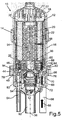
- Fig. 3 the closure device 70 is shown at a distance from a contact surface formed on the tubular receptacle 60. Accordingly, a seal 74 (in the present case arranged on the closure device 70) can be seen. Furthermore, in this state, the filtered oil can flow through a channel 76 provided on the side of the oil filter housing 14, which oil can exit from the channel 20 of the filter cartridge 12 via the passage openings 34.
- a seal 74 in the present case arranged on the closure device 70
- the filtered oil can flow through a channel 76 provided on the side of the oil filter housing 14, which oil can exit from the channel 20 of the filter cartridge 12 via the passage openings 34.
- the position shown of the closure device 70 in which the closure device 70 is moved away from the receptacle 60 against the force of the check valve spring 72, accordingly opens an inlet into the channel 76 provided on the side of the oil filter housing 14 for the filtered oil.
- the interaction of the filter cartridge 12 with the tubular receptacle 60 and the closure device 70 also provides a check valve 80 and a bypass valve 82 (cf. Fig. 1 ).
- the check valve 80 and the bypass valve 82 are closed.
- the check valve 80 is closed when the on the closure device 70 arranged seal 74 rests on the receptacle 60.
- the bypass valve 82 is closed when the seal 68 arranged in the present case on the receptacle 60 is in contact with the wall 66.
- the wall 66 thus serves, as it were, as a valve carrier for the bypass valve 82.
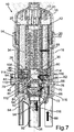
- Fig. 4 shows the oil filter 10 according to Fig. 1 in the sectional view, the oil filter housing 14 closed, that is to say the cover 18 is mounted on the base body 16.
- the internal combustion engine of the motor vehicle which has the oil filter 10
- an oil pump which conveys unfiltered oil to the filter cartridge 12 when the internal combustion engine is running, does not run either.
- the cover 18 is tightly mounted on the base body 16, the spring 46 presses the stamp-shaped end 48 of the sleeve element 44 against the inlet 56 of the drainage channel 54.
- the service valve 78 is correspondingly closed.
- the region 30 of the channel 20 is designed to be closed at the end, that is to say at its end facing the closure device 70.
- a (in the present case, conically designed) bottom part 84 of the channel 20 rests against the (presently also conically tapering) closure device 70 (cf. Fig. 15 ).
- the lower end plate 26 rests against an upper, axial end of the tubular receptacle 60.
- the lower end plate 26 is at a distance from the upper end of the receptacle 60, as shown in the first position.
- the nozzle-shaped region 30 of the channel 20, the bottom part 84 of which rests against the closure device 70 is inserted further into the tubular receptacle 60 when the filter cartridge 12 moves out of the first position in the axial direction 36 (cf. Fig. 4 ) in the second position (compare Fig. 5 ) is shifted.
- the area 30 of the filter cartridge 12 presses the closure device 70 away from the receptacle 60 against the force of the check valve spring 72.
- arrows illustrate the pressures which lead to the axial displacement of the floating filter cartridge 12 within the oil filter housing 14 when the oil pump conveys the unfiltered oil into the oil filter housing 14.
- first arrows 96 illustrate the pressure of the unfiltered oil on the upper end plate 28 of the filter cartridge 12.
- Further arrows 98 illustrate the pressure of the unfiltered oil on the lower end plate 26 of the filter cartridge 12.
- a third arrow 100 illustrates the pressure of the oil downstream of the filter material 22 which is correspondingly reduced compared to the pressure of the unfiltered oil due to the pressure loss.
- arrows 102 illustrate the spring force applied by the spring 46 and arrows 104 the spring force applied by the check valve spring 72. Accordingly, that illustrated by arrow 96 is Force greater than the sum of the forces illustrated by arrows 98, 100, 102, 104.
- the sealing ring or O-ring 106 arranged on the filter cartridge 12 or integrated into the filter cartridge 12 and axially displaceable together with the filter cartridge 12 enables the axial stroke of the filter cartridge 12, this sealing element ensuring that in the in Fig. 5
- a pre-filter screen can be provided for the case that the bypass valve 82 or pressure relief valve opens in the event of excess pressure.
- the forces of the check valve spring 72 or the bypass valve spring 62 are preferably designed so that the filter cartridge 12 does not vibrate during operation.
- the spring force of the bypass valve spring 62 is very much greater than the spring force of the check valve spring 72. This ensures that the bypass valve 82 only opens when, due to the pressure loss in the clogged or clogged filter material 22, the with reference to Fig. 7 and Fig. 8 The situation described occurs and, accordingly, both the check valve 80 and the bypass valve 82 are open.
- the connector-shaped region 120 of the channel 20 is inserted into the receptacle 130, which is provided on the side of the cover 18.
- the sealing rings 128 correspondingly rest against an inside of the tubular receptacle 130. Accordingly, no unfiltered oil can enter the passage openings 126. Consequently, the bypass valve 82 is also closed.
- the sealing rings 128 designed as radial seals in the area 120 of the channel 20 prevent the unfiltered oil from entering the channel 20 as long as the passage openings 126 are in overlap with the wall of the receptacle 130.
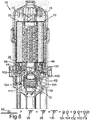
- the passage openings 34 which are formed in the region 30 of the channel 20 in the wall 32, are fluidically connected to an inlet in the channel 76 provided on the side of the oil filter housing 14. Filtered oil can therefore get into this channel 76 and the check valve 80 is open. In contrast, the service valve 78 is still closed. The bypass valve 82 is also still closed. In Fig. 13 The arrows 88 again illustrate the path of the unfiltered oil through the oil filter housing 14 and then in the radial direction through the filter material 22 into the channel 20. In an analogous manner, the arrows 94 illustrate the path of the filtered oil through the channel 20 and the passage openings 34 into the channel 76 and on to the internal combustion engine via the channel 92. The lower end plate 26 of the filter cartridge 12, however, does not yet lie against the receptacle 60.
- bypass valve 82 is now also open: the area 120 of the channel 20 has been moved out of the receptacle 130 so far that the unfiltered oil can reach the area 120 of the channel 20 via the passage openings 126.
- the corresponding flow path of the unfiltered oil is in Fig. 14 illustrated by further arrows 140.
- the unfiltered oil also reaches the channel 92 via the channel 76.
- the lower end plate 26 also rests on the upper end 108 of the sleeve element 44. Accordingly, the spring 46 is also compressed to a maximum extent.
- the check valve spring 72 is also compressed more than when the filter cartridge 12 is in the position shown in FIG Fig. 13 second position shown.
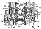
- FIGS. 15 to 17 further possible configurations of the area 30 of the channel 20 are to be illustrated.
- Fig. 15 the area 30 of the filter cartridge 12 is shown again enlarged, as it is in the case of the with reference to FIG FIGS. 1 to 14 Variants described can be used by way of example. Accordingly, the bottom part 84 is designed to be closed here.
Description
Die Erfindung betrifft einen Ölfilter mit einem Ölfiltergehäuse, in welchem eine Filterkartusche angeordnet ist. Des Weiteren betrifft die Erfindung eine Filterkartusche zum Einsetzen in das Ölfiltergehäuse des Ölfilters eines Kraftwagens. Die Filterkartusche weist einen Kanal für gefiltertes Öl auf, welcher in radialer Richtung zumindest bereichsweise von einem Filtermaterial der Filterkartusche umgeben ist.The invention relates to an oil filter with an oil filter housing in which a filter cartridge is arranged. The invention also relates to a filter cartridge for insertion into the oil filter housing of the oil filter of a motor vehicle. The filter cartridge has a channel for filtered oil, which is at least partially surrounded in the radial direction by a filter material of the filter cartridge.
Die
Die
Des Weiteren beschreibt die
Das aus dem Stand der Technik bekannte Rückschlagventil verhindert, dass bei einem Stopp des Verbrennungsmotors der Ölkreislauf leerläuft. Dem liegt die Erkenntnis zugrunde, dass alle Lager des Verbrennungsmotors mit Öl mit einem gewissen Druck zu beaufschlagen sind, damit die Schmierung der Lager gut funktioniert. Um jedoch einen entsprechenden Öldruck aufbauen zu können, ist es erforderlich, dass der Ölkreislauf mit Öl und nicht mit Luft befüllt ist. Ist kein Rückschlagventil vorgesehen, so bewirkt das Abstellen des Verbrennungsmotors, dass der Ölkreislauf größtenteils leerläuft. Das Rückschlagventil hilft also, auch bei einem Stopp des Verbrennungsmotors Ölvolumen im Ölkreislauf zu halten. Wenn nämlich aufgrund von Luft im Ölkreislauf der Öldruck nur verzögert aufgebaut werden kann, führt dies zu einer fehlenden oder mangelhaften Schmierung. Eine fehlende Schmierung kann jedoch zu Lagerschäden beziehungsweise zu Motorschäden führen. Eine mangelhafte Schmierung bedeutet einen höheren Verschleiß. Verschleißen Lager des Verbrennungsmotors, so führt dies zu einer Reduzierung der Lebensdauer des Verbrennungsmotors. Im schlimmsten Fall kann dies gar zu einem frühzeitigen Motorschaden führen.The check valve known from the prior art prevents the oil circuit from running empty when the internal combustion engine stops. This is based on the knowledge that all bearings of the internal combustion engine must be subjected to a certain pressure with oil so that the bearings can be lubricated properly. However, in order to be able to build up a corresponding oil pressure, it is necessary that the oil circuit is filled with oil and not with air. If no check valve is provided, switching off the internal combustion engine causes the oil circuit to run largely empty. The check valve therefore helps to keep the oil volume in the oil circuit even when the internal combustion engine stops. If, because of air in the oil circuit, the oil pressure can only build up with a delay, this leads to missing or inadequate lubrication. However, a lack of lubrication can lead to bearing damage or engine damage. Inadequate lubrication means greater wear and tear. If the bearings of the internal combustion engine wear out, this leads to a reduction in the service life of the internal combustion engine. In the worst case, this can even lead to premature engine damage.
Das Entlastungsventil oder Sicherheitsventil, welches auch als Bypassventil bezeichnet wird, öffnet jedoch bei verstopftem Filtermaterial einen Bypass. Das Öl durchströmt dann zwar nicht mehr das Filtermaterial, jedoch ist eine Notversorgung des Verbrennungsmotors zumindest mit ungefiltertem Öl gewährleistet.The relief valve or safety valve, which is also referred to as a bypass valve, opens a bypass when the filter material is clogged. The oil then no longer flows through the filter material, but an emergency supply of the internal combustion engine is at least guaranteed with unfiltered oil.
Bei der Anordnung derartiger Ventile in aus dem Stand der Technik bekannten Ölfiltern ist üblicherweise vorgesehen, dass entweder der Ventilsitz oder der Ventilkolben beziehungsweise Ventilpilz an der Filterkartusche angebracht ist und der jeweilige Gegenpart am Ölfiltergehäuse. Das Vorsehen derartiger Ventile führt jedoch zu einer vergleichsweise großen Bauteilanzahl und einer vergleichsweise hohen Komplexität des Ölfilters.When arranging such valves in oil filters known from the prior art, it is usually provided that either the valve seat or the valve piston or valve head is attached to the filter cartridge and the respective counterpart is attached to the oil filter housing. The provision of such valves, however, leads to a comparatively large number of components and a comparatively high complexity of the oil filter.
Aufgabe der vorliegenden Erfindung ist es daher, eine Filterkartusche der eingangs genannten Art und einen Ölfilter mit einer solchen Filterkartusche zu schaffen, durch welche beziehungsweise bei welchem auf vereinfachte Art zumindest eine Ventilfunktion bereitgestellt ist.The object of the present invention is therefore to create a filter cartridge of the type mentioned at the beginning and an oil filter with such a filter cartridge, by means of which or in which at least one valve function is provided in a simplified manner.
Diese Aufgabe wird durch einen Ölfilter mit den Merkmalen des Patentanspruchs 1 und durch eine Filterkartusche mit den Merkmalen des Patentanspruchs 9 gelöst. Vorteilhafte Ausgestaltungen mit zweckmäßigen Weiterbildungen der Erfindung sind in den abhängigen Patentansprüchen angegeben.This object is achieved by an oil filter with the features of claim 1 and by a filter cartridge with the features of claim 9. Advantageous configurations with expedient developments of the invention are specified in the dependent claims.
Der erfindungsgemäße Ölfilter für einen Kraftwagen umfasst eine Filterkartusche und ein Ölfiltergehäuse, in welchem die Filterkartusche angeordnet ist. Die Filterkartusche weist einen Kanal für gefiltertes Öl auf. In radialer Richtung ist der Kanal zumindest bereichsweise von einem Filtermaterial der Filterkartusche umgeben. In einer Wandung des Kanals ist zumindest eine Durchtrittsöffnung ausgebildet. Das Ölfiltergehäuse umfasst einen Grundkörper und ein Deckelelement. Bei von dem Grundkörper abgenommenem Deckelelement kann die Filterkartusche aus dem Ölfiltergehäuse entfernt werden.The oil filter according to the invention for a motor vehicle comprises a filter cartridge and an oil filter housing in which the filter cartridge is arranged. The filter cartridge has a channel for filtered oil. In the radial direction, the channel is at least partially surrounded by a filter material of the filter cartridge. At least one passage opening is formed in a wall of the channel. The oil filter housing comprises a base body and a cover element. With the cover element removed from the base body, the filter cartridge can be removed from the oil filter housing.
Des Weiteren ist die Filterkartusche in dem geschlossenen Ölfiltergehäuse, bei welchem das Deckelelement an den Grundkörper montiert ist, aus einer ersten Position, in welcher ein Eintreten von gefiltertem Öl über die zumindest eine Durchtrittsöffnung in einen auf Seiten des Ölfiltergehäuses vorgesehenen Kanal für das gefilterte Öl unterbunden ist, in eine zweite Position bewegbar. In der zweiten Position ist die Filterkartusche bezogen auf die erste Position in eine axiale Richtung der Filterkartusche verschoben. In der zweiten Position ist ein Einlass in den auf Seiten des Ölfiltergehäuses vorgesehenen Kanal mit der zumindest einen Durchtrittsöffnung fluidisch verbunden. So ist auf besonders einfache Weise im Zusammenwirken der Filterkartusche mit dem Ölfiltergehäuse ein Rückschlagventil bereitgestellt.Furthermore, the filter cartridge in the closed oil filter housing, in which the cover element is mounted on the base body, is prevented from a first position in which the entry of filtered oil via the at least one passage opening into a channel for the filtered oil provided on the side of the oil filter housing is movable to a second position. In the second position, the filter cartridge is displaced in an axial direction of the filter cartridge in relation to the first position. In the second position, an inlet into the channel provided on the side of the oil filter housing is fluidically connected to the at least one passage opening. A check valve is thus provided in a particularly simple manner in the interaction of the filter cartridge with the oil filter housing.
Die Filterkartusche weist ein relativ zu einer ersten Endplatte der Filterkartusche in die axiale Richtung der Filterkartusche verschiebbares Verschlusselement auf. Mittels des Verschlusselements ist ein Ablasskanal verschließbar, welcher zum Ablassen des Öls aus einem Aufnahmebereich des Ölfiltergehäuses für die Filterkartusche vorgesehen ist. Hierbei ist ein Einlass des Ablasskanals durch Verbringen der Filterkartusche in eine Demontageposition der Filterkartusche freigebbar. In der Demontageposition ist die Filterkartusche aus der ersten Position in eine der zweiten Position entgegengesetzte Richtung bewegt. Entsprechend ist durch das Verschlusselement im Zusammenwirken mit dem Ablasskanal ein Serviceventil bereitgestellt. Bei geöffnetem Serviceventil und somit freigegebenem Einlass des Ablasskanals kann bei einem Ölwechsel gewährleistet werden, dass das gesamte gebrauchte Öl aus dem Verbrennungsmotor abgelassen wird. So kann die Filterkartusche ohne eine Ölverschleppung gewechselt werden.The filter cartridge has a closure element that can be displaced in the axial direction of the filter cartridge relative to a first end plate of the filter cartridge. A drainage channel can be closed by means of the closure element and is provided for draining the oil from a receiving area of the oil filter housing for the filter cartridge. Here, an inlet of the outlet channel can be released by moving the filter cartridge into a dismantling position of the filter cartridge. In the dismantling position, the filter cartridge is moved from the first position into a direction opposite to the second position. Accordingly, a service valve is provided by the closure element in cooperation with the drainage channel. When the service valve is open and the inlet of the drain channel is released, it can be ensured that all the used oil is drained from the internal combustion engine when the oil is changed. In this way, the filter cartridge can be changed without the oil being carried over.
Die erfindungsgemäße Filterkartusche, welche in das Ölfiltergehäuse des Ölfilters eingesetzt werden kann, weist den Kanal für gefiltertes Öl auf. In radialer Richtung ist der Kanal zumindest bereichsweise von dem Filtermaterial der Filterkartusche umgeben. In der Wandung des Kanals ist die zumindest eine Durchtrittsöffnung ausgebildet. Durch Verbringen der Filterkartusche in die erste Position kann ein Eintreten von gefiltertem Öl über die zumindest eine Durchtrittsöffnung in den Kanal für das gefilterte Öl unterbunden werden, welcher auf Seiten des Ölfiltergehäuses vorgesehen ist. Durch Verbringen der Filterkartusche in die zweite Position, in welcher die Filterkartusche bezogen auf die erste Position in eine axiale Richtung der Filterkartusche verschoben ist, ist der Einlass in den auf Seiten des Ölfiltergehäuses vorgesehenen Kanal mit der zumindest einen Durchtrittsöffnung fluidisch verbindbar. In der ersten Position der Filterkartusche kann also das gefilterte Öl nicht die zumindest eine Durchtrittsöffnung in der Wandung des Kanals der Filterkartusche durchströmen und weiter in den auf Seiten des Ölfiltergehäuses vorgesehenen Kanal gelangen. Demgegenüber kann die fluidische Verbindung zwischen dem Kanal der Filterkartusche und dem auf Seiten des Ölfiltergehäuses vorgesehenen Kanal hergestellt werden, indem die Filterkartusche in die zweite Position verbracht wird. Bei fluidischer Verbindung der zumindest einen Durchtrittsöffnung mit dem Einlass des auf Seiten des Ölfiltergehäuses vorgesehenen Kanal kann dementsprechend das gefilterte Öl die zumindest eine Durchtrittsöffnung durchströmen und über den Einlass in den Kanal gelangen, welcher auf Seiten des Ölfiltergehäuses für das gefilterte Öl vorgesehen ist.The filter cartridge according to the invention, which can be inserted into the oil filter housing of the oil filter, has the channel for filtered oil. In the radial direction, the channel is at least partially surrounded by the filter material of the filter cartridge. The at least one passage opening is formed in the wall of the channel. By moving the filter cartridge into the first position, the entry of filtered oil via the at least one passage opening into the channel for the filtered oil, which is provided on the side of the oil filter housing, can be prevented. By moving the filter cartridge into the second position, in which the filter cartridge is displaced in an axial direction of the filter cartridge relative to the first position, the inlet into the channel provided on the oil filter housing side can be fluidically connected to the at least one passage opening. In the first position of the filter cartridge, the filtered oil cannot flow through the at least one passage opening in the wall of the channel of the filter cartridge and continue into the channel provided on the side of the oil filter housing. In contrast, the fluidic connection between the channel of the filter cartridge and the channel provided on the side of the oil filter housing can be established by bringing the filter cartridge into the second position. When the at least one passage opening is fluidically connected to the inlet of the channel provided on the side of the oil filter housing, the filtered oil can accordingly flow through the at least one passage opening and via the inlet into the channel which is provided on the side of the oil filter housing for the filtered oil.
Die Filterkartusche weist das relativ zu der ersten Endplatte der Filterkartusche in die axiale Richtung der Filterkartusche verschiebbare Verschlusselement auf. Mittels des Verschlusselements ist der Ablasskanal verschließbar, welcher zum Ablassen des Öls aus dem Aufnahmebereich des Ölfiltergehäuses für die Filterkartusche vorgesehen ist. Hierbei ist der Einlass des Ablasskanals durch Verbringen der Filterkartusche in die Demontageposition der Filterkartusche freigebbar. In der Demontageposition ist die Filterkartusche aus der ersten Position in eine der zweiten Position entgegengesetzte Richtung bewegt. Entsprechend ist durch das Verschlusselement im Zusammenwirken mit dem Ablasskanal ein Serviceventil bereitgestellt. Bei geöffnetem Serviceventil und somit freigegebenem Einlass des Ablasskanals kann bei einem Ölwechsel gewährleistet werden, dass das gesamte gebrauchte Öl aus dem Verbrennungsmotor abgelassen wird. So kann die Filterkartusche ohne eine Ölverschleppung gewechselt werden.The filter cartridge has the closure element which can be displaced in the axial direction of the filter cartridge relative to the first end plate of the filter cartridge. The drainage channel, which is provided for draining the oil from the receiving area of the oil filter housing for the filter cartridge, can be closed by means of the closure element. Here, the inlet of the outlet channel can be released by moving the filter cartridge into the dismantling position of the filter cartridge. In the dismantling position, the filter cartridge is moved from the first position into a direction opposite to the second position. Accordingly, a service valve is provided by the closure element in cooperation with the drainage channel. When the service valve is open and the inlet of the drain channel is released, it can be ensured that all the used oil is drained from the internal combustion engine when the oil is changed. In this way, the filter cartridge can be changed without the oil being carried over.
Die Filterkartusche ist also in dem Ölfiltergehäuse in die axiale Richtung der Filterkartusche verschiebbar, welche mit der axialen Richtung des Kanals der Filterkartusche zusammenfällt. Diese Verschieberichtung entspricht des Weiteren einer Richtung, in welche beim Einbau der Filterkartusche in das Ölfiltergehäuse die Filterkartusche in das Ölfiltergehäuse eingesetzt oder eingeschoben wird.The filter cartridge can therefore be displaced in the oil filter housing in the axial direction of the filter cartridge, which coincides with the axial direction of the channel of the filter cartridge. This displacement direction also corresponds to a direction in which the filter cartridge is inserted or pushed into the oil filter housing when the filter cartridge is installed in the oil filter housing.
Mit anderen Worten ist die Filterkartusche in dem Ölfiltergehäuse schwimmend gelagert. Dies bedeutet, dass die Filterkartusche entlang eines definierten Verfahrwegs oder Verschiebewegs axial in dem Ölfiltergehäuse bewegbar ist. Durch dieses Bewegen der Filterkartusche in die axiale Richtung kann dafür gesorgt werden, dass die zumindest eine Durchtrittsöffnung, welche in der Wandung des Kanals der Filterkartusche ausgebildet ist, mit dem Einlass in den auf Seiten des Ölfiltergehäuses vorgesehenen Kanal fluidisch verbunden wird. In dieser zweiten Position der Filterkartusche kann also das gefilterte Öl aus dem Kanal der Filterkartusche in den auf Seiten des Ölfiltergehäuses vorgesehenen Kanal für das gefilterte Öl eintreten. Befindet sich hingegen die Filterkartusche in der ersten Position, so ist die zumindest eine Durchtrittsöffnung in der Wandung des Kanals der Filterkartusche nicht von Öl durchströmbar. Entsprechend ist durch das Verbringen der Filterkartusche in die erste Position das Eintreten des gefilterten Öls in den auf Seiten des Ölfiltergehäuses vorgesehenen Kanal unterbindbar.In other words, the filter cartridge is floatingly mounted in the oil filter housing. This means that the filter cartridge can be moved axially in the oil filter housing along a defined travel path or displacement path. By moving the filter cartridge in the axial direction, it can be ensured that the at least one passage opening which is formed in the wall of the channel of the filter cartridge is fluidically connected to the inlet in the channel provided on the side of the oil filter housing. In this second position of the filter cartridge, the filtered oil can enter the channel for the filtered oil from the channel of the filter cartridge into the channel provided on the side of the oil filter housing. If, on the other hand, the filter cartridge is in the first position, the at least one passage opening in the wall of the channel of the filter cartridge cannot be flowed through by oil. Correspondingly, by moving the filter cartridge into the first position, the filtered oil can be prevented from entering the channel provided on the side of the oil filter housing.
Es ist also durch die axial verschiebbare Filterkartusche, bei welcher in der Wandung des Kanals die zumindest eine Durchtrittsöffnung vorgesehen ist, im Zusammenwirken mit dem auf Seiten des Ölfiltergehäuses vorgesehenen Kanal ein Rückschlagventil bereitgestellt. Wenn nämlich der Öldruck einer Ölpumpe im Betrieb des Ölfilters die Filterkartusche in die zweite Position verschiebt, so kann das gefilterte Öl in den auf Seiten des Ölfiltergehäuses vorgesehenen Kanal gelangen. Das gefilterte Öl steht dann für das Schmieren eines Verbrennungsmotors des Kraftwagens zur Verfügung.A check valve is therefore provided by the axially displaceable filter cartridge, in which the at least one passage opening is provided in the wall of the channel, in cooperation with the channel provided on the side of the oil filter housing. If the oil pressure of an oil pump moves the filter cartridge into the second position during operation of the oil filter, the filtered oil can get into the channel provided on the side of the oil filter housing. The filtered oil is then available for lubricating an internal combustion engine of the motor vehicle.
Die Bereitstellung des Rückschlagventils ist besonders einfach; es kann nämlich vorliegend auf ein relativ zu der Filterkartusche bewegbares, verschleißanfälliges Betätigungselement zum Öffnen des Rückschlagventils verzichtet werden. Vielmehr führt die Bewegung der gesamten Filterkartusche in die axiale Richtung zum Öffnen des Rückschlagventils. Es wird also das Rückschlagventil durch wenige Bauteile und bei besonders geringer Komplexität des Ölfilters bereitgestellt.The provision of the check valve is particularly simple; In the present case, an actuating element which is susceptible to wear and which is movable relative to the filter cartridge for opening the check valve can be dispensed with. Rather, the movement of the entire filter cartridge in the axial direction leads to the opening of the check valve. The check valve is thus provided by a few components and with a particularly low complexity of the oil filter.
Vorliegend wird also der Druckverlust über die Filterkartusche dazu verwendet, die axiale Bewegung der Filterkartusche zu erzeugen beziehungsweise zu bewirken. Die Differenz des Drucks des ungefilterten Öls auf die Filterkartusche gegenüber dem Druck des gefilterten Öls auf die Filterkartusche wird vorliegend also genutzt, um das Rückschlagventil aufzudrücken.In the present case, the pressure loss across the filter cartridge is used to generate or effect the axial movement of the filter cartridge. The difference the pressure of the unfiltered oil on the filter cartridge compared to the pressure of the filtered oil on the filter cartridge is used in the present case to push the check valve open.
Bevorzugt wird dann, wenn die Ölpumpe keinen Druck mehr aufbaut, also beim Abstellen des Verbrennungsmotors, die Filterkartusche in die erste Position verschoben. Dies kann durch ein Federelement bewirkt sein, welches auf Seiten des Ölfiltergehäuses und/oder auf Seiten der Filterkartusche angeordnet sein kann. In dieser ersten Position der Filterkartusche sorgt das Unterbinden des Durchströmtwerdens der zumindest einen Durchtrittsöffnung in der Wandung des Kanals der Filterkartusche dafür, dass der Druck im Ölkreislauf erhalten bleibt und somit der Ölkreislauf nicht leerläuft. Entsprechend ist durch die axial verschiebbare Filterkartusche auf vereinfachte Art eine Ventilfunktion bereitgestellt, nämlich die Funktion eines Rückschlagventils. Dadurch, dass die Filterkartusche selber als verschiebbarer Ventilkolben ausgeführt ist, lässt sich eine Reduzierung der Bauteilanzahl, des Gewichts und der Komplexität des die Filterkartusche aufweisenden Ölfilters erreichen. Des Weiteren sind so Vorteile im Hinblick auf für den Ölfilter vorzusehenden Bauraum erreichbar.When the oil pump no longer builds up pressure, that is, when the internal combustion engine is switched off, the filter cartridge is preferably moved into the first position. This can be brought about by a spring element which can be arranged on the side of the oil filter housing and / or on the side of the filter cartridge. In this first position of the filter cartridge, preventing the flow through the at least one passage opening in the wall of the channel of the filter cartridge ensures that the pressure in the oil circuit is maintained and thus the oil circuit does not run empty. Correspondingly, the axially displaceable filter cartridge provides a valve function in a simplified manner, namely the function of a check valve. Because the filter cartridge itself is designed as a displaceable valve piston, the number of components, the weight and the complexity of the oil filter having the filter cartridge can be reduced. Furthermore, advantages with regard to the installation space to be provided for the oil filter can be achieved in this way.
Bei aus dem Stand der Technik bekannten Rückschlagventilen im Ölkreislauf kann es, je nach Einbaulage des Rückschlagventils, dazu kommen, dass zumindest die Reinölseite des Bereichs des Ölfilters leerläuft, in welchem sich die Filterkartusche befindet. Dies führt dazu, dass bei einem Start des Verbrennungsmotors der Aufbau von Druck im Öl länger dauert, als dies wünschenswert ist. Dadurch, dass vorliegend dieses Leerlaufen verhindert ist, ergibt sich eine erhöhte Menge an im Ölkreislauf zurückgehaltenem Öl. Dies führt zu einem besonders raschen Öldruckaufbau nach dem Start des Verbrennungsmotors des Kraftwagens.In the case of check valves in the oil circuit known from the prior art, depending on the installation position of the check valve, at least the clean oil side of the area of the oil filter in which the filter cartridge is located can run empty. As a result, when the internal combustion engine is started, the build-up of pressure in the oil takes longer than is desirable. Because this idling is prevented in the present case, there is an increased amount of oil retained in the oil circuit. This leads to a particularly rapid build-up of oil pressure after the internal combustion engine of the motor vehicle has started.
Die verringerte Anzahl an vorzusehenden Bauteilen betrifft einerseits die Einzelteile der unterschiedlichen Ventile wie etwa des Rückschlagventils und des Bypassventils. Des Weiteren kann ein Stützdom entfallen, welcher bei aus dem Stand der Technik bekannten Ölfiltern vorgesehen ist, um Öl, welches sich im Bereich der Filterkartusche befindet, bei einem Stopp des Verbrennungsmotors im Ölfilter zurückzuhalten. Darüber hinaus lässt sich durch das Vorsehen einer Mehrzahl von Durchtrittsöffnungen in der Wandung des Kanals der Filterkartusche ein besonders großer durchströmbarer Querschnitt, also ein erhöhter Ventilquerschnitt, zur Verfügung stellen. Dies verringert den durch den Ölfilter und insbesondere durch die Filterkartusche bedingten Druckverlust im Betrieb des Ölfilters. Da die Ölpumpe üblicherweise mittels des Verbrennungsmotors angetrieben wird, führt der reduzierte Druckverlust auch zu einer Reduzierung des Kraftstoffverbrauchs des Verbrennungsmotors. Die Kraftstoffersparnis geht mit einem hohen Kosten-Nutzen-Verhältnis einher.The reduced number of components to be provided relates on the one hand to the individual parts of the different valves such as the check valve and the bypass valve. Furthermore, a support dome can be omitted, which is provided in oil filters known from the prior art in order to retain oil that is located in the area of the filter cartridge in the oil filter when the internal combustion engine stops. In addition, by providing a plurality of passage openings in the wall of the channel of the filter cartridge, a particularly large cross-section through which a flow can flow, that is to say an increased valve cross-section, can be made available. This reduces the pressure loss caused by the oil filter and in particular by the filter cartridge when the oil filter is in operation. Since the oil pump is usually driven by means of the internal combustion engine the reduced pressure loss also leads to a reduction in the fuel consumption of the internal combustion engine. The fuel savings go hand in hand with a high cost-benefit ratio.
Dadurch, dass Bauteile beziehungsweise Bauteilgruppen entfallen können beziehungsweise entsprechende Funktionsträger in das Ölfiltergehäuse integriert sein können, ergibt sich des Weiteren eine Kostenreduktion. Des Weiteren ist so eine kostengünstige und robuste Lösung bereitgestellt, welche insbesondere für den Einsatz in einer Serienfertigung, insbesondere Großserienfertigung geeignet ist.The fact that components or component groups can be omitted or corresponding function carriers can be integrated into the oil filter housing furthermore results in a cost reduction. Furthermore, a cost-effective and robust solution is provided which is particularly suitable for use in series production, in particular large series production.
Vorliegend wird zwar das zum Schmieren des Verbrennungsmotors des Kraftwagens eingesetzte Medium als Öl bezeichnet, jedoch ist auch eine Verwendung der Filterkartusche für andere Medien, insbesondere für andere Schmiermittel als Öl möglich.In the present case, the medium used to lubricate the internal combustion engine of the motor vehicle is referred to as oil, but it is also possible to use the filter cartridge for other media, in particular for lubricants other than oil.
Vorzugsweise ist durch Verbringen der Filterkartusche in eine dritte Position, in welcher die Filterkartusche bezogen auf die zweite Position weiter in die axiale Richtung der Filterkartusche verschoben ist, ein Einlass für ungefiltertes Öl in einen Kanal freigebbar. Der Einlass ist durch Verbringen der Filterkartusche in die erste Position und durch Verbringen der Filterkartusche in die zweite Position verschließbar. In der dritten Position der Filterkartusche kann dementsprechend ungefiltertes Öl in den Kanal gelangen, dessen Einlass freigegeben ist. Entsprechend ist durch das Verschieben der Filterkartusche in die dritte Position ein Bypassventil beziehungsweise Entlastungsventil oder Überdruckventil bereitgestellt.Preferably, by moving the filter cartridge into a third position, in which the filter cartridge is displaced further in the axial direction of the filter cartridge relative to the second position, an inlet for unfiltered oil into a channel can be released. The inlet can be closed by moving the filter cartridge into the first position and by moving the filter cartridge into the second position. In the third position of the filter cartridge, unfiltered oil can accordingly enter the channel, the inlet of which is open. Correspondingly, by moving the filter cartridge into the third position, a bypass valve or relief valve or pressure relief valve is provided.
Dieses Bypassventil sorgt dafür, dass beispielsweise bei verstopftem Filtermaterial der Filterkartusche zumindest ungefiltertes Öl zum Verbrennungsmotor des Kraftwagens gelangen kann. In der ersten und in der zweiten Position der Filterkartusche ist dieser Einlass für das ungefilterte Öl nicht freigegeben, sondern verschlossen. So ist dafür gesorgt, dass bei abgestelltem Verbrennungsmotor und bei laufendem Verbrennungsmotor kein ungefiltertes Öl in den Kanal gelangt, sofern nicht das Filtermaterial der Filterkartusche zugesetzt oder verstopft ist.This bypass valve ensures that, for example, if the filter material in the filter cartridge is clogged, at least unfiltered oil can reach the internal combustion engine of the motor vehicle. In the first and second position of the filter cartridge, this inlet for the unfiltered oil is not released, but closed. This ensures that when the internal combustion engine is switched off and the internal combustion engine is running, no unfiltered oil gets into the duct, unless the filter material of the filter cartridge is clogged or clogged.
Der Kanal der Filterkartusche kann einen ersten Bereich aufweisen, welcher an die erste Endplatte der Filterkartusche angrenzt und in welchem die zumindest eine Durchtrittsöffnung ausgebildet ist. Der Kanal der Filterkartusche kann des Weiteren einen zweiten Bereich aufweisen, in welchem durch wenigstens eine weitere Durchtrittsöffnung der Einlass für das ungefilterte Öl in den Kanal bereitgestellt ist. Durch Verbringen der Filterkartusche in die dritte Position ist das ungefilterte Öl über die wenigstens eine weitere Durchtrittsöffnung in den Kanal der Filterkartusche einbringbar. Entsprechend kann also der Kanal der Filterkartusche bei dieser Ausgestaltung sowohl von gefiltertem Öl als auch - bei geöffnetem Bypassventil - von ungefiltertem Öl durchströmt werden. Das ungefilterte Öl kann jedoch lediglich dann in diesen Kanal gelangen, wenn die Filterkartusche in die dritte Position verschoben ist.The channel of the filter cartridge can have a first region which adjoins the first end plate of the filter cartridge and in which the at least one passage opening is formed. The channel of the filter cartridge can furthermore have a second area in which the inlet for the unfiltered oil into the channel is provided through at least one further passage opening. By spending the Filter cartridge in the third position, the unfiltered oil can be introduced into the channel of the filter cartridge via the at least one further passage opening. Accordingly, in this embodiment, both filtered oil and, when the bypass valve is open, unfiltered oil can flow through the channel of the filter cartridge. However, the unfiltered oil can only get into this channel when the filter cartridge is moved to the third position.
Das Verschieben der Filterkartusche aus der zweiten Position in die dritte Position erfolgt bevorzugt gegen die Federkraft eines Federelements. Hierbei bringt die Federkraft bevorzugt einen Druck auf die Filterkartusche auf, welcher wesentlich größer ist als der bei nicht verstopftem oder zugesetztem Filtermaterial auf die Filterkartusche wirkende Betriebsdruck, welcher die Filterkartusche aus der ersten Position in die zweite Position verschiebt.The filter cartridge is preferably moved from the second position into the third position against the spring force of a spring element. Here, the spring force preferably applies a pressure to the filter cartridge which is significantly greater than the operating pressure acting on the filter cartridge when the filter material is not clogged or clogged and which moves the filter cartridge from the first position to the second position.
Bevorzugt ist der zweite Bereich als endseitig geschlossener und rohrförmiger Stutzen ausgebildet, wobei an einer Außenseite des Stutzens wenigstens ein Dichtelement angeordnet ist. Vorzugsweise sind hierbei - in die Bewegungsrichtung der Filterkartusche beim Bewegen derselben aus der ersten Position in die zweite Position gesehen - beidseitig der wenigstens einen weiteren Durchtrittsöffnung Dichtelemente an der Außenseite des Stutzens angeordnet. Durch das Vorsehen derartiger radialer Dichtungen kann besonders einfach und zuverlässig sichergestellt werden, dass lediglich dann ungefiltertes Öl die weitere Durchtrittsöffnung durchströmt, wenn die Filterkartusche in die dritte Position verschoben ist.The second area is preferably designed as a tubular connecting piece which is closed at the end, at least one sealing element being arranged on an outside of the connecting piece. In this case, as seen in the direction of movement of the filter cartridge when it is moved from the first position to the second position, sealing elements are preferably arranged on both sides of the at least one further passage opening on the outside of the connecting piece. By providing such radial seals, it can be ensured in a particularly simple and reliable manner that unfiltered oil only flows through the further passage opening when the filter cartridge is shifted into the third position.
In der Demontageposition ist entsprechend das Verschlusselement von dem Ablasskanal beabstandet. Insbesondere kann die Filterkartusche in der Demontageposition an einem Deckelelement des Ölfiltergehäuses gehalten sein. Hierfür können an der Filterkartusche Krallen oder dergleichen Halteelemente vorgesehen sein, welche mit auf Seiten des Deckelelements vorgesehenen Krallen oder dergleichen Halteelementen zusammenwirken können. Die Länge der Krallen der Filterkartusche und des Deckelelements ist hierbei so bemessen, dass die axiale Verschiebbarkeit der Filterkartusche aus der ersten Position in die zweite Position und aus der zweiten Position in die dritte Position gewährleistet ist.In the dismantling position, the closure element is correspondingly spaced from the drainage channel. In particular, the filter cartridge can be held in the dismantling position on a cover element of the oil filter housing. For this purpose, claws or similar holding elements can be provided on the filter cartridge, which can interact with claws or similar holding elements provided on the side of the cover element. The length of the claws of the filter cartridge and the cover element is dimensioned such that the axial displaceability of the filter cartridge from the first position into the second position and from the second position into the third position is guaranteed.
Das Verschlusselement kann als Hülsenelement ausgebildet sein, welches einen Aufnahmeraum begrenzt. Der Aufnahmeraum ist zwischen einem ersten Bereich des die zumindest eine Durchtrittsöffnung aufweisenden Kanals der Filterkartusche und dem Hülsenelement ausgebildet. Hierbei weist das Hülsenelement wenigstens eine Durchtrittsöffnung auf, über welche das ungefilterte Öl in den Aufnahmeraum einbringbar ist. In der dritten Position der Filterkartusche ist das ungefilterte Öl aus dem Aufnahmeraum in den auf Seiten des Ölfiltergehäuses vorgesehenen Kanal einbringbar.The closure element can be designed as a sleeve element which delimits a receiving space. The receiving space is between a first region of the channel of the filter cartridge, which has the at least one passage opening, and the Sleeve element formed. Here, the sleeve element has at least one passage opening through which the unfiltered oil can be introduced into the receiving space. In the third position of the filter cartridge, the unfiltered oil can be introduced from the receiving space into the channel provided on the side of the oil filter housing.
Bei einer derartigen Ausgestaltung kann insbesondere durch das Vorsehen von in axialer Richtung (also in die axiale Richtung der Filterkartusche) gegen eine entsprechende Anlagefläche gepressten Dichtungen die Funktion des Bypassventils oder Überdruckventils bereitgestellt werden. Derartige axiale Dichtungen sorgen für eine besonders verschleißarme, zuverlässige und funktionssichere Abdichtung bei geschlossenem Ventil.In such a configuration, the function of the bypass valve or pressure relief valve can be provided in particular by the provision of seals pressed in the axial direction (that is, in the axial direction of the filter cartridge) against a corresponding contact surface. Such axial seals ensure a particularly low-wear, reliable and functionally safe seal when the valve is closed.
Das Hülsenelement kann insbesondere entlang einer von der ersten Endplatte der Filterkartusche abstehenden Wandung der Filterkartusche verschiebbar sein. Durch eine derartige, insbesondere ebenfalls hülsenförmige Wandung kann eine besonders exakte und prozesssichere Führung des Hülsenelements beim Verschieben desselben sichergestellt werden.The sleeve element can in particular be displaceable along a wall of the filter cartridge protruding from the first end plate of the filter cartridge. By means of such a wall, in particular likewise sleeve-shaped, a particularly precise and process-reliable guidance of the sleeve element can be ensured when it is moved.
Ein Federelement zum Verschieben des Verschlusselements ist bevorzugt auf Seiten der Filterkartusche bereitgestellt. Entsprechend kann an der Filterkartusche ein Federelement angeordnet sein, mittels welchem das Verschlusselement in einer den Einlass des Ablasskanals verschließenden Stellung mit einer Federkraft des Federelements beaufschlagt ist. Dann wird dieses Federelement zum Bewegen des Verschlusselements gemeinsam mit der Filterkartusche getauscht, wenn die Filterkartusche ausgewechselt wird. Somit kann einem Verschleiß des Federelements besonders gut Rechnung getragen werden.A spring element for moving the closure element is preferably provided on the side of the filter cartridge. Accordingly, a spring element can be arranged on the filter cartridge, by means of which the closure element is acted upon by a spring force of the spring element in a position closing the inlet of the outlet channel. Then this spring element for moving the closure element is exchanged together with the filter cartridge when the filter cartridge is exchanged. Wear of the spring element can thus be taken into account particularly well.
Das Federelement kann insbesondere aus einem Kunststoff gebildet sein. Dadurch ist es möglich, die gesamte Filterkartusche einschließlich des Federelements einer Entsorgung durch Verbrennen zuzuführen. Denn hierbei verbrennt das aus dem Kunststoff gebildete Federelement mit. Dies verringert den Aufwand bei der Entsorgung der gebrauchten Filterkartusche.The spring element can in particular be formed from a plastic. This makes it possible to dispose of the entire filter cartridge including the spring element by burning it. Because here the spring element formed from the plastic also burns. This reduces the effort involved in disposing of the used filter cartridge.
Des Weiteren weist bevorzugt das Verschlusselement wenigstens ein Dichtelement auf, welches zum Abdichten des Einlasses des Ablasskanals vorgesehen ist. Dann wird nämlich auch dieses in die axiale Richtung der Filterkartusche wirkende wenigstens eine Dichtelement beim Austausch der Filterkartusche mit ausgetauscht. Entsprechend kann so auch einem Verschleiß des Dichtelements zum Abdichten des Einlasses des Ablasskanals vereinfacht Rechnung getragen werden.Furthermore, the closure element preferably has at least one sealing element which is provided for sealing the inlet of the outlet channel. Then this at least one sealing element acting in the axial direction of the filter cartridge is also replaced when the filter cartridge is replaced. Accordingly can thus also wear of the sealing element for sealing the inlet of the outlet channel can be taken into account in a simplified manner.
Als weiter vorteilhaft hat es sich gezeigt, wenn an einer Außenseite eines Bereichs des Kanals der Filterkartusche, welcher die zumindest eine Durchtrittsöffnung aufweist, ein Dichtelement angeordnet ist. Das Dichtelement läuft in radialer Richtung um den Bereich des Kanals um. Das Dichtelement ist in eine Strömungsrichtung des gefilterten Öls durch den Kanal der Filterkartusche betrachtet stromaufwärts der zumindest einen Durchtrittsöffnung angeordnet. Beispielsweise kann das Dichtelement durch wenigstens eine O-Ring-Dichtung bereitgestellt sein. Durch eine derartige radiale Dichtung kann besonders einfach sichergestellt werden, dass im Normalbetrieb, also bei (noch) nicht verstopftem beziehungsweise zugesetztem Filtermaterial lediglich gefiltertes Öl in den auf Seiten des Ölfiltergehäuses vorgesehenen Kanal für das gefilterte Öl gelangt.It has also been shown to be advantageous if a sealing element is arranged on an outside of a region of the channel of the filter cartridge which has the at least one passage opening. The sealing element runs around the area of the channel in the radial direction. The sealing element is arranged upstream of the at least one passage opening, viewed in a flow direction of the filtered oil through the channel of the filter cartridge. For example, the sealing element can be provided by at least one O-ring seal. Such a radial seal makes it particularly easy to ensure that in normal operation, that is, when the filter material is not (yet) clogged or clogged, only filtered oil gets into the channel for the filtered oil provided on the side of the oil filter housing.
Durch entsprechende Auslegung der Federelemente des Ölfilters kann dafür gesorgt werden, dass die Filterkartusche im Betrieb nicht schwingt, also keine rasch wechselnden Bewegungen in die axiale Richtung der Filterkartusche auftreten. Des Weiteren sind hierfür bevorzugt in den jeweiligen Positionen der Filterkartusche definierte Zwischenanschläge vorgesehen. Darüber hinaus können auf Seiten der Filterkartusche und/oder auf Seiten des Ölfiltergehäuses Dämpfungsvolumina mit als Drossel wirkenden Durchtrittsöffnungen beziehungsweise Bohrungen vorgesehen sein. Auch dies dient dem Vermeiden eines axialen Schwingens der Filterkartusche.Appropriate design of the spring elements of the oil filter can ensure that the filter cartridge does not vibrate during operation, i.e. that there are no rapidly changing movements in the axial direction of the filter cartridge. Furthermore, for this purpose, defined intermediate stops are preferably provided in the respective positions of the filter cartridge. In addition, damping volumes with passage openings or bores acting as throttles can be provided on the side of the filter cartridge and / or on the side of the oil filter housing. This also serves to avoid axial oscillation of the filter cartridge.
Die für die erfindungsgemäße Filterkartusche beschriebenen Vorteile und bevorzugten Ausführungsformen gelten auch für den erfindungsgemäßen Ölfilter und umgekehrt.The advantages and preferred embodiments described for the filter cartridge according to the invention also apply to the oil filter according to the invention and vice versa.
Hierbei bewirkt bevorzugt ein Federelement das Verschieben der Filterkartusche aus der zweiten Position in die erste Position, wenn ein Verbrennungsmotor des Kraftwagens abgeschaltet ist. Gegen den Druck dieses Federelements bewirkt bei laufendem Verbrennungsmotor eine Ölpumpe hingegen das Verschieben der Filterkartusche aus der ersten Position in die zweite Position. Der Hub beziehungsweise der Weg des Verschiebens der Filterkartusche in die axiale Richtung resultiert hierbei aus der Druckdifferenz des auf jeweilige Bereiche der Filterkartusche drückenden Öls unter Berücksichtigung der von dem Federelement aufgebrachten Federkraft.In this case, a spring element preferably causes the filter cartridge to be displaced from the second position into the first position when an internal combustion engine of the motor vehicle is switched off. In contrast to the pressure of this spring element, when the internal combustion engine is running, an oil pump moves the filter cartridge from the first position to the second position. The stroke or the displacement of the filter cartridge in the axial direction results from the pressure difference of the oil pressing on the respective areas of the filter cartridge, taking into account the spring force applied by the spring element.
Durch einen solchen Ölfilter ist eine Vereinfachung insbesondere im Hinblick auf die Bereitstellung der unterschiedlichen Ventilfunktionen erreicht. Dies gilt insbesondere für die Integration des Rückschlagventils in die Filterkartusche beziehungsweise das Filterelement. Bevorzugt sind jedoch sowohl die Funktionen des Rückschlagventils als auch des Serviceventils und des Bypassventils in einen Ventilkolben in Form der axial verschiebbaren, also schwimmend gelagerten Filterkartusche integriert ausgeführt. Durch die in die axiale Richtung beweglich beziehungsweise schwimmend gelagerte Filterkartusche lassen sich Vorteile im Hinblick auf eine Kombination der durch die Filterkartusche bewirkten Filtrationen des Öls und die Ventilsteuerung erreichen.Such an oil filter achieves a simplification, in particular with regard to the provision of the different valve functions. This is especially true for the integration of the check valve in the filter cartridge or the filter element. However, the functions of the check valve as well as the service valve and the bypass valve are preferably implemented in a valve piston in the form of the axially displaceable, that is to say floatingly mounted, filter cartridge. The filter cartridge, which is movably or floatingly mounted in the axial direction, allows advantages with regard to a combination of the oil filtrations effected by the filter cartridge and the valve control.
Bevorzugt weist das Ölfiltergehäuse eine rohrförmige Aufnahme auf, in welcher ein die zumindest eine Durchtrittsöffnung aufweisender erster Bereich des Kanals der Filterkartusche aufgenommen ist, wenn die Filterkartusche in die erste Position oder in die zweite Position verbracht ist. Der erste Bereich des Kanals liegt zumindest in der ersten Position und in der zweiten Position der Filterkartusche an einer Verschlusseinrichtung an. Die Verschlusseinrichtung ist durch Verschieben der Filterkartusche aus der ersten Position in die zweite Position von der rohrförmigen Aufnahme weg bewegbar, um den Einlass in den auf Seiten des Ölfiltergehäuses vorgesehenen Kanal freizugeben. Die Druckdifferenz zwischen dem ungefilterten Öl und dem gefilterten Öl auf der Reinölseite des Filtermaterials führt im Betrieb des Ölfilters, also bei laufendem Verbrennungsmotor und somit angetriebener Ölpumpe, zum Freigeben des Einlasses in den auf Seiten des Ölfiltergehäuses vorgesehenen Kanal, indem die Filterkartusche die Verschlusseinrichtung verschiebt.The oil filter housing preferably has a tubular receptacle in which a first region of the channel of the filter cartridge that has the at least one passage opening is received when the filter cartridge is brought into the first position or into the second position. The first region of the channel rests against a closure device at least in the first position and in the second position of the filter cartridge. The closure device can be moved away from the tubular receptacle by moving the filter cartridge from the first position into the second position in order to open the inlet into the channel provided on the side of the oil filter housing. The pressure difference between the unfiltered oil and the filtered oil on the pure oil side of the filter material leads to the opening of the inlet into the channel provided on the side of the oil filter housing when the oil filter is in operation, i.e. when the internal combustion engine and the oil pump is running, as the filter cartridge moves the locking device.
Hierbei kann die Filterkartusche die Verschlusseinrichtung gegen die Federkraft eines Federelements verschieben. Durch das Anliegen des ersten Bereichs des Kanals der Filterkartusche an der Verschlusseinrichtung ist ein definierter Zwischenanschlag beim Bewegen der Filterkartusche bereitgestellt. Dies macht das Bereitstellen der wenigstens einen Ventilfunktion besonders prozesssicher.Here, the filter cartridge can move the closure device against the spring force of a spring element. The fact that the first region of the channel of the filter cartridge rests against the closure device provides a defined intermediate stop when the filter cartridge is moved. This makes the provision of the at least one valve function particularly process-reliable.
Vorzugsweise weist das Ölfiltergehäuse einen Anschlag für ein Federelement auf, welches bei einem Verbringen der Filterkartusche in eine dritte Position, in welcher die Filterkartusche bezogen auf die zweite Position noch weiter in die axiale Richtung der Filterkartusche verschoben ist, eine entgegen der Verschieberichtung wirkende Federkraft auf die Filterkartusche ausübt. Durch ein solches Federelement kann gezielt die Federkraft aufgebracht werden, welche zu überwinden ist, um das Öffnen des Bypassventils zu bewirken.The oil filter housing preferably has a stop for a spring element which, when the filter cartridge is moved into a third position in which the filter cartridge is displaced even further in the axial direction of the filter cartridge relative to the second position, exerts a spring force acting counter to the displacement direction Filter cartridge exercises. By means of such a spring element, the spring force which has to be overcome in order to bring about the opening of the bypass valve can be applied in a targeted manner.
Hierbei kann durch ein Wegbewegen der rohrförmigen Aufnahme von einer Wandung des Ölfiltergehäuses ein Einlass für ungefiltertes Öl in einen Kanal freigebbar sein. Entsprechend kann durch das Wegbewegen der rohrförmigen Aufnahme von der Wandung der Einlass in den Kanal freigegeben werden. Das Wegbewegen der rohrförmigen Aufnahme von der Wandung kann beispielsweise dadurch bewirkt werden, dass die rohrförmige Wandung an einer Endplatte der Filterkartusche anliegt und aufgrund des zugesetzten oder verstopften Filtermaterials ein erhöhter Druck auf der Seite des ungefilterten Öls im Vergleich zu dem Druck auf der Reinölseite der Filterkartusche vorliegt. Entsprechend schiebt dann die Filterkartusche die rohrförmige Aufnahme von der Wandung des Ölfiltergehäuses weg. Auch hier ist durch das Anliegen der rohrförmigen Aufnahme an der Endplatte der Filterkartusche ein Zwischenanschlag bereitgestellt, welcher dem prozesssicheren Verschieben der Filterkartusche zuträglich ist.In this case, by moving the tubular receptacle away from a wall of the oil filter housing, an inlet for unfiltered oil into a channel can be released. Correspondingly, by moving the tubular receptacle away from the wall, the inlet into the channel can be released. The tubular receptacle can be moved away from the wall, for example, in that the tubular wall rests against an end plate of the filter cartridge and, due to the added or clogged filter material, there is an increased pressure on the unfiltered oil side compared to the pressure on the clean oil side of the filter cartridge is present. The filter cartridge then accordingly pushes the tubular receptacle away from the wall of the oil filter housing. Here, too, because the tubular receptacle rests on the end plate of the filter cartridge, an intermediate stop is provided which is conducive to the process-reliable displacement of the filter cartridge.
Zusätzlich oder alternativ kann durch ein Herausbewegen eines zweiten, wenigstens eine weitere Durchtrittsöffnung aufweisenden Bereichs des Kanals der Filterkartusche aus einer auf Seiten des Deckelelements bereitgestellten weiteren rohrförmigen Aufnahme für den zweiten Bereich des Kanals ein Einlass für ungefiltertes Öl in einen Kanal freigegeben werden. Die weitere rohrförmige Aufnahme für den zweiten Bereich des Kanals kann insbesondere eine Einströmöffnung für ungefiltertes Öl aufweisen. Auf diese Weise bewirken Schwankungen im Druck des ungefilterten Öls nicht unmittelbar ein Verschieben der Filterkartusche. Vielmehr sorgt das Hindurchströmen des ungefilterten Öls durch die wenigstens eine Einströmöffnung in der rohrförmigen Aufnahme für eine Dämpfung. Die wenigstens eine Einströmöffnung dient somit als Drossel, welche ein axiales Schwingen der Filterkartusche verhindert.Additionally or alternatively, by moving a second region of the channel of the filter cartridge with at least one further passage opening out of a further tubular receptacle provided on the side of the cover element for the second region of the channel, an inlet for unfiltered oil can be released into a channel. The further tubular receptacle for the second region of the channel can in particular have an inflow opening for unfiltered oil. In this way, fluctuations in the pressure of the unfiltered oil do not immediately cause the filter cartridge to move. Rather, the flow of the unfiltered oil through the at least one inflow opening in the tubular receptacle ensures damping. The at least one inflow opening thus serves as a throttle which prevents the filter cartridge from oscillating axially.
Schließlich hat es sich als vorteilhaft gezeigt, wenn das Ölfiltergehäuse den Ablasskanal aufweist, wobei der Einlass des Ablasskanals mittels des relativ zu der ersten Endplatte der Filterkartusche in die axiale Richtung der Filterkartusche verschiebbaren Verschlusselements verschlossen ist, wenn sich die Filterkartusche in der ersten Position oder in der zweiten Position befindet. Durch das Vorsehen eines solchen Ablasskanals kann im Zusammenwirken mit dem Verschlusselement besonders einfach ein Serviceventil bereitgestellt werden.Finally, it has been shown to be advantageous if the oil filter housing has the outlet channel, the inlet of the outlet channel being closed by means of the closure element which can be displaced in the axial direction of the filter cartridge relative to the first end plate of the filter cartridge when the filter cartridge is in the first position or in the second position. By providing such a discharge channel, a service valve can be provided in a particularly simple manner in cooperation with the closure element.
Die vorstehend in der Beschreibung genannten Merkmale und Merkmalskombinationen sowie die nachfolgend in der Figurenbeschreibung genannten und/oder in den Figuren alleine gezeigten Merkmale und Merkmalskombinationen sind nicht nur in der jeweils angegebenen Kombination, sondern auch in anderen Kombinationen oder in Alleinstellung verwendbar, ohne den Rahmen der Erfindung zu verlassen. Es sind somit auch Ausführungen als von der Erfindung umfasst und offenbart anzusehen, die in den Figuren nicht explizit gezeigt oder erläutert sind, jedoch durch separierte Merkmalskombinationen aus den erläuterten Ausführungen hervorgehen und erzeugbar sind. Es sind somit auch Ausführungen und Merkmalskombinationen als offenbart anzusehen, die nicht alle Merkmale eines ursprünglich formulierten unabhängigen Anspruchs aufweisen. Es sind darüber hinaus Ausführungen und Merkmalskombinationen, insbesondere durch die oben dargelegten Ausführungen, als offenbart anzusehen, die über die in den Rückbezügen der Ansprüche dargelegten Merkmalskombinationen hinausgehen oder von diesen abweichen.The features and feature combinations mentioned above in the description as well as the features and feature combinations mentioned below in the description of the figures and / or shown alone in the figures are not only in the respective specified combination, but can also be used in other combinations or on their own without departing from the scope of the invention. Thus, embodiments are also to be regarded as encompassed and disclosed by the invention, which are not explicitly shown or explained in the figures, but which emerge and can be generated from the explained embodiments by means of separate combinations of features. Thus, designs and combinations of features that do not have all of the features of an originally formulated independent claim are also to be regarded as disclosed. In addition, designs and combinations of features, in particular through the statements set out above, are to be regarded as disclosed which go beyond the combinations of features set forth in the back-references of the claims or differ from them.
Weitere Vorteile, Merkmale und Einzelheiten der Erfindung ergeben sich aus den Ansprüchen, der nachfolgenden Beschreibung bevorzugter Ausführungsformen sowie anhand der Zeichnungen. Dabei zeigen:
- Fig. 1
- in einer Schnittansicht einen Ölfilter eines Kraftwagens, wobei ein Ölfiltergehäuse des Kraftwagens geöffnet ist und eine Filterkartusche in das Ölfiltergehäuse eingebaut wird;
- Fig. 2
- in einer vergrößerten Detailansicht einen Endbereich der Filterkartusche;
- Fig. 3
- in einer Detailansicht auf Seiten des Ölfiltergehäuses vorgesehene Komponenten des Ölfilters;
- Fig. 4
- den Ölfilter gemäß
Fig. 1 bei geschlossenem Ölfiltergehäuse und ausgeschaltetem Verbrennungsmotor; - Fig. 5
- den Ölfilter gemäß
Fig. 1 bei geschlossenem Ölfiltergehäuse bei laufendem Verbrennungsmotor; - Fig. 6
- schematisch die Kräfte, welche beim Verschieben der Filterkartusche gemäß
Fig. 5 wirken; - Fig. 7
- die bei zugesetztem Filtermaterial noch weiter in die axiale Richtung verschobene Filterkartusche, wobei ein Bypassventil geöffnet wird;
- Fig. 8
- die beim Öffnen des Bypassventils gemäß
Fig. 7 wirkenden Kräfte; - Fig. 9
- in einer Schnittansicht eine Variante des Ölfilters bei geöffnetem Ölfiltergehäuse mit einer sich in einer Servicestellung befindenden Filterkartusche, wobei in das Ölfiltergehäuse eine Variante der Filterkartusche eingebaut wird;
- Fig. 10
- in einer vergrößerten Detailansicht einen Ausschnitt der Filterkartusche gemäß
Fig. 9 - Fig. 11
- in einer vergrößerten Detailansicht Komponenten des Ölfiltergehäuses gemäß
Fig. 9 ; - Fig. 12
- den Ölfilter gemäß
Fig. 9 mit geschlossenem Ölfiltergehäuse und in das Ölfiltergehäuse eingebauter Filterkartusche bei nicht laufendem Verbrennungsmotor; - Fig. 13
- den Ölfilter gemäß
Fig. 9 bei laufendem Verbrennungsmotor; - Fig. 14
- das Öffnen eines Bypassventils bei laufendem Verbrennungsmotor und verstopftem Filtermaterial bei der Variante des Ölfilters gemäß
Fig. 9 ; - Fig. 15
- in einer vergrößerten Schnittansicht eine Möglichkeit der Ausgestaltung eines Endbereichs eines Kanals der Filterkartusche, wobei der Endbereich des Kanals endseitig geschlossen ist;
- Fig. 16
- eine Variante der Filterkartusche, wobei der Endbereich des Kanals endseitig offen ist; und
- Fig. 17
- eine weitere Variante der Filterkartusche, wobei im Endbereich des Kanals ein Druckstück vorgesehen ist.
- Fig. 1
- in a sectional view an oil filter of a motor vehicle, wherein an oil filter housing of the motor vehicle is opened and a filter cartridge is installed in the oil filter housing;
- Fig. 2
- in an enlarged detailed view, an end region of the filter cartridge;
- Fig. 3
- Components of the oil filter provided in a detailed view on the side of the oil filter housing;
- Fig. 4
- the oil filter according to
Fig. 1 with the oil filter housing closed and the combustion engine switched off; - Fig. 5
- the oil filter according to
Fig. 1 with the oil filter housing closed and the combustion engine running; - Fig. 6
- schematically the forces which occur when moving the filter cartridge according to
Fig. 5 works; - Fig. 7
- the filter cartridge, which is displaced further in the axial direction when the filter material is added, a bypass valve being opened;
- Fig. 8
- when opening the bypass valve according to
Fig. 7 acting forces; - Fig. 9
- a sectional view of a variant of the oil filter with the oil filter housing open with a filter cartridge in a service position, a variant of the filter cartridge being built into the oil filter housing;
- Fig. 10
- in an enlarged detailed view a section of the filter cartridge according to FIG
Fig. 9 - Fig. 11
- in an enlarged detailed view of components of the oil filter housing according to FIG
Fig. 9 ; - Fig. 12
- the oil filter according to
Fig. 9 with closed oil filter housing and filter cartridge built into the oil filter housing when the internal combustion engine is not running; - Fig. 13
- the oil filter according to
Fig. 9 with the internal combustion engine running; - Fig. 14
- the opening of a bypass valve while the internal combustion engine is running and the filter material is clogged in the variant of the oil filter according to
Fig. 9 ; - Fig. 15
- in an enlarged sectional view, a possibility of designing an end region of a channel of the filter cartridge, the end region of the channel being closed at the end;
- Fig. 16
- a variant of the filter cartridge, the end region of the channel being open at the end; and
- Fig. 17
- Another variant of the filter cartridge, a pressure piece being provided in the end area of the channel.
Die Filterkartusche 12 weist einen Kanal 20 auf, welcher in radialer Richtung von einem Filtermaterial 22 umgeben ist. Das Filtermaterial 22 kann beispielsweise als Faltenfilter ausgebildet sein. Der Kanal 20 ist rohrförmig ausgebildet und weist in dem Bereich, in welchem er von dem Filtermaterial 22 umgeben ist, eine Vielzahl von Ausnehmungen 24 auf. Über diese Ausnehmungen 24 kann das mittels des Filtermaterials 22 gefilterte Öl in den Kanal 20 gelangen. Das ungefilterte Öl tritt dementsprechend in radialer Richtung, also von außen her durch das Filtermaterial 22 hindurch und gelangt so in den Kanal 20.The
Der Kanal 20 ist in einem Bereich zwischen einer ersten, gemäß
Von der oberen oder zweiten Endplatte 28 stehen in eine axiale Richtung 36 der Filterkartusche 12 mehrere Krallen 38 im Wesentlichen senkrecht ab. Die Krallen 38 sind mit korrespondierenden Krallen 40 in Eingriff, welche an dem Deckel 18 des Ölfiltergehäuses 14 vorgesehen sind. Über dieses Zusammenwirken der Krallen 38, 40 hängt die Filterkartusche 12 am Deckel 18, wenn die Filterkartusche 12 aus dem Grundkörper 16 des Ölfiltergehäuses 14 herausgenommen wird und wenn eine ungebrauchte, also neue Filterkartusche 12 anschließend in den Grundkörper 16 des Ölfiltergehäuses 14 eingesetzt wird. Die axiale Richtung 36 entspricht somit auch der Richtung, in welche beim Einbau der Filterkartusche 12 die Filterkartusche 12 in den im Wesentlichen rohrförmigen Grundkörper 16 des Ölfiltergehäuses 14 eingeschoben beziehungsweise eingesetzt wird.A plurality of
In Zusammenschau von
In der in
Anhand von
Die Dichtung 68 kann an der Aufnahme 60 und/oder an der Wandung 66 angeordnet sein. Vorliegend sind die Wandung 66 und der Bereich 64 dort trichterförmig beziehungsweise konisch ausgebildet, wo sich die Dichtung 68 befindet. Entsprechend ist auch die Dichtung 68 vorliegend bezogen auf die axiale Richtung 36 schräg angeordnet. In Varianten des Ölfilters 10 kann an dieser Stelle jedoch bei entsprechender Gestaltung der Aufnahme 60 und der Wandung 66 auch wenigstens eine ebene beziehungsweise waagerecht angeordnete Dichtung vorgesehen sein.The
Innerhalb der rohrförmigen Aufnahme 60 ist des Weiteren eine haubenförmige beziehungsweise domartige Verschlusseinrichtung 70 angeordnet. Diese Verschlusseinrichtung 70 wird in die axiale Richtung 36 von einem weiteren Federelement in Form einer Rückschlagventilfeder 72 mit einer Federkraft beaufschlagt. Die Rückschlagventilfeder 72 drückt die Verschlusseinrichtung 70 gegen die rohrförmige Aufnahme 60 (vergleiche
In
Im Folgenden werden die mittels der Filterkartusche 12 realisierbaren Ventilfunktionen genauer erläutert. Durch das Zusammenwirken des Hülsenelements 44 mit der axialen Dichtung in Form der Dichtringe 50, 52 mit dem Einlass 56 des Ablasskanals 54 ist vorliegend ein Serviceventil 78 bereitgestellt. In der in
Durch das Zusammenwirken der Filterkartusche 12 mit der rohrförmigen Aufnahme 60 und der Verschlusseinrichtung 70 sind des Weiteren ein Rückschlagventil 80 und ein Bypassventil 82 bereitgestellt (vergleiche
Bei der in
In der in
Das von der Ölpumpe des Kraftwagens in den Zulaufkanal 86 eingebrachte, ungefilterte Öl übt auf die Filterkartusche 12 einen gewissen Druck aus. Von Bedeutung für das axiale Verschieben der Filterkartusche 12 in eine in
Des Weiteren liegt die untere Endplatte 26 an einem oberen, axialen Ende der rohrförmigen Aufnahme 60 an. In der in
In
Ein Dichtelement, welches vorliegend beispielhaft als O-Ring 106 ausgebildet ist, ist im Bereich 30 des Kanals 20 an einer Außenseite der Wandung 32 angeordnet (vergleiche
Durch das Öl, welches sich im Bereich der Rückschlagventilfeder 72 befindet, ist ein hydraulischer Dämpferbereich bereitgestellt. Dadurch führen Druckschwankungen des Öls nicht zu einem axialen Schwingen mit geringer Amplitude, also zu einem rasch wechselnden hin und her Bewegen der Filterkartusche 12 innerhalb des Ölfiltergehäuses 14 in die axiale Richtung 36. Um dieses hydraulische Dämpfungsverhalten zu verbessern, können etwa im Bereich einer Wandung, an welcher die Rückschlagventilfeder 72 anliegt, Drosselbohrungen oder dergleichen durchströmbare Öffnungen vorgesehen sein.The oil, which is located in the area of the
Jedoch bewirkt das axiale Verschieben der Filterkartusche 12 in die axiale Richtung 36 in die in
Das ungefilterte Öl kann über vorliegend als Schlitze 114 ausgebildete Durchtrittsöffnungen, welche sowohl in der hülsenförmigen Wandung 42 als auch in dem Hülsenelement 44 ausgebildet sind (vergleiche
Des Weiteren veranschaulichen die Pfeile 88, 94 den zusätzlich weiterhin möglichen Weg des Öls in den Kanal 92 durch das Filtermaterial 22 hindurch und anschließend entlang des Kanals 20 der Filterkartusche 12. Zu der in
Die entsprechenden Kräfte sind in
Die Kräfte der Rückschlagventilfeder 72 beziehungsweise der Bypassventilfeder 62 sind bevorzugt so ausgelegt, dass die Filterkartusche 12 im Betrieb nicht schwingt. Insbesondere ist die Federkraft der Bypassventilfeder 62 sehr viel größer als die Federkraft der Rückschlagventilfeder 72. Dies sorgt dafür, dass das Bypassventil 82 nur dann öffnet, wenn aufgrund des Druckverlusts im zugesetzten beziehungsweise verstopften Filtermaterial 22 die mit Bezug auf
Jedoch ist die obere Endplatte 28 bei der in
In der in
Demgegenüber ist das Rückschlagventil 80 anders ausgebildet als bei der in
Bei der in
In der in
Der stutzenförmige Bereich 120 des Kanals 20 ist in die Aufnahme 130 eingeführt, welche auf Seiten des Deckels 18 vorgesehen ist. Die Dichtringe 128 liegen entsprechend an einer Innenseite der rohrförmigen Aufnahme 130 an. Dementsprechend kann kein ungefiltertes Öl in die Durchtrittsöffnungen 126 eintreten. Folglich ist auch das Bypassventil 82 geschlossen.The connector-shaped
Jedoch kann über Einströmöffnungen 138, welche in der Aufnahme 130 vorgesehen sind, ungefiltertes Öl in einen durch das Deckelteil 122 begrenzten Aufnahmeraum innerhalb der Aufnahme 130 gelangen. Dadurch ist ein hydraulischer Dämpfungsbereich bereitgestellt. Die Einströmöffnungen 138 wirken hierbei als Drosselelemente. Diese dämpfen bei etwaigen Druckschwankungen im Ölfiltergehäuse 14 ein Schwingen beziehungsweise rasches sich hin und her Bewegen der Filterkartusche 12 in die axiale Richtung 36. Dadurch, dass ein axiales Schwingen der Filterkartusche 12 verhindert ist, ist auch die Abnutzung der radialen Dichtung, vorliegend also des O-Rings 106, besonders gering.However, unfiltered oil can pass through
Die als radiale Dichtungen ausgebildeten Dichtringe 128 im Bereich 120 des Kanals 20 verhindern ein Eintreten des ungefilterten Öls in den Kanal 20, solange sich die Durchtrittsöffnungen 126 in Überdeckung mit der Wandung der Aufnahme 130 befinden.The sealing rings 128 designed as radial seals in the
Dementsprechend sind die Durchtrittsöffnungen 34, welche in dem Bereich 30 des Kanals 20 in der Wandung 32 ausgebildet sind, fluidisch mit einem Einlass in den auf Seiten des Ölfiltergehäuses 14 vorgesehenen Kanal 76 verbunden. Es kann also gefiltertes Öl in diesen Kanal 76 gelangen, und das Rückschlagventil 80 ist geöffnet. Das Serviceventil 78 ist demgegenüber weiterhin geschlossen. Auch ist das Bypassventil 82 weiterhin geschlossen. In
In der in
Demgegenüber ist nun auch das Bypassventil 82 geöffnet: Der Bereich 120 des Kanals 20 ist so weit aus der Aufnahme 130 heraus bewegt, dass das ungefilterte Öl über die Durchtrittsöffnungen 126 in den Bereich 120 des Kanals 20 gelangen kann. Der entsprechende Strömungsweg des ungefilterten Öls ist in
Sowohl bei der in
In den vorliegend gezeigten Varianten ist die dem Verschließen des Serviceventils 78 dienende Feder 46 Bestandteil der Filterkartusche 12. Es ist jedoch auch möglich, ein derartiges Federelement auf Seiten des Ölfiltergehäuses 14 vorzusehen. Des Weiteren ist die schwimmende Lagerung der Filterkartusche 12 vorliegend mit Bezug auf den Ölfilter 10 für ein Nutzfahrzeug beschrieben. Jedoch lässt sich das Öffnen zumindest des Rückschlagventils 80 und des Bypassventils 82 durch das axiale Verschieben der Filterkartusche 12 auch bei einem Ölfilter nutzen, wie er in einem Personenkraftwagen zum Einsatz kommt. Hier ist lediglich die Funktion des Serviceventils 78 nicht erforderlich. Denn bei einem Ölfilter für einen Personenkraftwagen wird die Filterkartusche 12 üblicherweise von unten in das Ölfiltergehäuse montiert beziehungsweise nach unten aus dem Ölfiltergehäuse entnommen, sodass das abzulassende Öl durch die entsprechende untenliegende Öffung ungehindert ablaufen kann.In the variants shown here, the
Anhand von
Bei der in
Bei der in
Claims (11)
- Oil filter for a motor vehicle, with a filter cartridge (12) located in an oil filter housing (14) of the oil filter (10), wherein the oil filter housing (14) comprises a base body (16) and a cover element (18), wherein the filter cartridge (12) has a first - lower-and a second - upper - end plate (26, 28) and a passage (20) for filtered oil, which is surrounded by a filter material (22) of the filter cartridge (12) in the radial direction at least in certain areas, wherein at least one through-opening (34) is formed in a wall (32) of the passage (20) in a region (30) adjoining the lower end plate (26) as a tubular connector, wherein the filter cartridge (12) can be moved in the closed oil filter housing (14), in which the cover element (18) is mounted on the base body (16), from a first position in which an entry of filtered oil via the at least one through-opening (34) into a passage (76) for filtered oil provided on the side of the oil filter housing (14) is prevented into a second position in which the filter cartridge (12) is displaced in an axial direction (36) of the filter cartridge (12) with respect to the first position and in which an inlet into the passage (76) provided on the side of the oil filter housing (14) is fluidically connected to the at least one through-opening (34), characterised in that
from the lower end plate (26) of the filter cartridge (12) a sleeve-shaped wall (42) projects in the axial direction (36), along which wall (34) a sleeve element (44) serving as a closing element is guided in the oil filter housing (14) in an axially displaceable manner, by means of which sleeve element (44) an annular inlet (56) of a discharge passage (54) for discharging the oil from a reception region of the oil filter housing (14) for the filter cartridge (12) can be closed, wherein the annular inlet (56) of the discharge passage (54) can be released by moving the filter cartridge (12) into a removal position of the filter cartridge (12), in which the filter cartridge (12) is moved from the first position in a direction counter to the second position. - Oil filter according to claim 1,
characterised in that
a spring element (46), which is formed from a plastic material in particular and by means of which a spring force of the spring element (46) is applied to the closing element (44) in a position closing the inlet (56) of the discharge passage (54), is located at the filter cartridge (12). - Oil filter according to claim 1 or 2,
characterised in that
the closing element (44) has at least one sealing element (50, 52) designed for sealing the inlet (56) of the discharge passage (54). - Oil filter according to any of claims 1 to 3,
characterised in that
the oil filter housing (14) has the discharge passage (54), wherein the inlet (56) of the discharge passage (54) is closed by means of the closing element (44) displaceable relative to the first end plate (26) of the filter cartridge (12) in the axial direction (36) of the filter cartridge (12) if the filter cartridge (12) is in the first position or in the second position. - Oil filter according to claim 2 or to any of claims 3 to 4 with reference to claim 2, characterised in that
in a third position of the filter cartridge (12), in which the filter cartridge (12) has been displaced further in the axial direction (36) of the filter cartridge (12) with respect to the second position, the first end plate (26) bears against an upper end (108) of the closing element (44), the spring element (46) being compressed to its maximum extent. - Oil filter according to any of claims 1 to 5,
characterised in that
the oil filter housing (14) has a tubular receptacle (60), in which a first region (30) of the passage (20) of the filter cartridge (12) having the at least one through-opening (34) is accommodated if the filter cartridge (12) has been moved into the first position or into the second position, wherein the first region (30) of the passage (20) bears at least in the first position and in the second position against a closing device (70), which, in particular against the spring force of a spring element (72), can be moved away from the tubular receptacle (60) by displacing the filter cartridge (12) from the first position into the second position, in order to open up the inlet into the passage (76) on the side of the oil filter housing (14) - Oil filter according to claim 6,
characterised in that
the oil filter housing (14) has a stop for a spring element (62), which applies a spring force acting against the displacement direction to the filter cartridge (12) at a movement of the filter cartridge (12) into a third position in which the filter cartridge (12) has been displaced further in the axial direction (36) of the filter cartridge (12) with respect to the second position, wherein an inlet for unfiltered oil into a passage (110, 92) can be opened up by moving the tubular receptacle (60) away from a wall (66) of the oil filter housing (14). - Oil filter according to any of claims 1 to 6,
characterised in that
the oil filter housing (14) has a stop for a spring element (62), which applies a spring force acting against the displacement direction to the filter cartridge (12) at a movement of the filter cartridge (12) into a third position in which the filter cartridge (12) has been displaced further in the axial direction (36) of the filter cartridge (12) with respect to the second position, wherein an inlet for unfiltered oil into a passage (110, 92) can be opened up by moving out a second region (120) of the passage (20) of the filter cartridge (12) having at least one further through-opening (126) from a further tubular receptacle (130) provided on the side of the cover element (18), in particular having an inflow opening (138) for unfiltered oil, for the second region (120) of the passage (20). - Filter cartridge for installation into an oil filter housing (14) of an oil filter (10) according to any of claims 1 to 7, having a first - lower - and a second - upper - end plate (26, 28) and a passage (20) for filtered oil, which is surrounded by filter material (22) at least in certain areas, wherein at least one through-opening (34) is formed in a wall (32) of the passage (20) in a region (30) adjoining the lower end plate (26) as a tubular connector,
characterised in that
from the lower end plate (26) a sleeve-shaped wall (42) projects in the axial direction (36), along which wall (42) a sleeve element (44) serving as a closing element is guided in the oil filter housing (14) in an axially displaceable manner for closing an annular inlet (56) of a discharge passage (54), wherein, by applying pressure to the upper end plate (28) in the direction of the lower end plate (26), the first region (30) - having the at least one through-opening (34) - of the passage (20) of the filter cartridge (12) can be displaced in the axial direction (36) until an upper end (108) of the sleeve element (44) comes to bear against the lower end plate (26), whereby, when the filter cartridge (12) is installed into the oil filter housing (14), valve functions of the oil filter (1) can be effected by means of pressure differentials induced in the operation of the oil filter (1) between filtered and unfiltered oil. - Filter cartridge according to claim 9,
characterised in that
a spring element (46), by means of which a spring force of the spring element (46) can be applied to a sleeve element (44) serving as closing element in a position closing the inlet (56) of the discharge passage (54), is located at the filter cartridge (12). - Filter cartridge according to claim 10 for installation into an oil filter housing (14) of an oil filter (10) according to claim 8 or 9,
characterised in that
the filter cartridge (12) has a second region (120) of the passage (20) having at least one further through-opening (126).
Priority Applications (1)
| Application Number | Priority Date | Filing Date | Title |
|---|---|---|---|
| PL16798089.5T PL3380211T4 (en) | 2015-11-28 | 2016-11-17 | Filter cartridge for a vehicule oil filter and oil filter |
Applications Claiming Priority (2)
| Application Number | Priority Date | Filing Date | Title |
|---|---|---|---|
| DE102015015370.6A DE102015015370A1 (en) | 2015-11-28 | 2015-11-28 | Filter device for an oil filter of a motor vehicle and oil filter |
| PCT/EP2016/001914 WO2017088962A1 (en) | 2015-11-28 | 2016-11-17 | Filter cartridge for an oil filter of a motor vehicle, and oil filter |
Publications (2)
| Publication Number | Publication Date |
|---|---|
| EP3380211A1 EP3380211A1 (en) | 2018-10-03 |
| EP3380211B1 true EP3380211B1 (en) | 2022-01-05 |
Family
ID=57348628
Family Applications (1)
| Application Number | Title | Priority Date | Filing Date |
|---|---|---|---|
| EP16798089.5A Active EP3380211B1 (en) | 2015-11-28 | 2016-11-17 | Filter cartridge for a vehicule oil filter and oil filter |
Country Status (11)
| Country | Link |
|---|---|
| US (1) | US11504656B2 (en) |
| EP (1) | EP3380211B1 (en) |
| JP (1) | JP6648274B2 (en) |
| KR (1) | KR102155947B1 (en) |
| CN (1) | CN108290094B (en) |
| BR (1) | BR112018009703B8 (en) |
| DE (1) | DE102015015370A1 (en) |
| ES (1) | ES2909125T3 (en) |
| PL (1) | PL3380211T4 (en) |
| WO (1) | WO2017088962A1 (en) |
| ZA (1) | ZA201803977B (en) |
Families Citing this family (5)
| Publication number | Priority date | Publication date | Assignee | Title |
|---|---|---|---|---|
| DE102018009928A1 (en) * | 2018-12-17 | 2020-06-18 | Daimler Ag | Oil filter for a motor vehicle and filter cartridge for an oil filter |
| CN112844832B (en) * | 2020-12-29 | 2022-06-14 | 徐州中液过滤技术有限公司 | Linear gap type oil return oil filter convenient for cleaning filter screen |
| CN113058306B (en) * | 2021-03-23 | 2022-06-07 | 重庆医药高等专科学校 | Traditional chinese medicine liquid medicine filter equipment |
| KR102428701B1 (en) | 2021-05-18 | 2022-08-04 | 이선호 | Reusable metal cartridges for vehicles oil filter and methods thereof |
| EP4311589A1 (en) * | 2022-07-28 | 2024-01-31 | Hamilton Sundstrand Corporation | Filter valve assembly |
Citations (2)
| Publication number | Priority date | Publication date | Assignee | Title |
|---|---|---|---|---|
| JP2004346929A (en) * | 2003-05-21 | 2004-12-09 | Arvin Technologies Inc | Quick discharge valve member for filter device |
| DE102009054523A1 (en) * | 2009-12-10 | 2011-06-16 | Hengst Gmbh & Co. Kg | liquid filters |
Family Cites Families (21)
| Publication number | Priority date | Publication date | Assignee | Title |
|---|---|---|---|---|
| DE3422482A1 (en) * | 1984-06-16 | 1985-12-19 | Filterwerk Mann & Hummel Gmbh, 7140 Ludwigsburg | LIQUID FILTER FOR THE LUBRICANT OR FUEL OF AN INTERNAL COMBUSTION ENGINE |
| US4812230A (en) | 1988-02-26 | 1989-03-14 | C.I.B., Inc. | Fluid filter |
| US5284579A (en) * | 1992-08-31 | 1994-02-08 | Dana Corporation | One-piece anti-drainback and relief valve |
| DE29917563U1 (en) | 1999-09-09 | 2001-02-01 | Hengst Walter Gmbh & Co Kg | Fluid filter with housing-fixed drain dome |
| WO2001017657A2 (en) | 1999-09-09 | 2001-03-15 | Ing. Walter Hengst Gmbh & Co. Kg | Fluid filter with a discharge dome that is fixed to the housing |
| JP3893313B2 (en) | 2002-04-26 | 2007-03-14 | 東洋▲ろ▼機製造株式会社 | Fluid filter |
| JP4094909B2 (en) * | 2002-08-09 | 2008-06-04 | 株式会社日立製作所 | Oil filter |
| DE10333398A1 (en) | 2003-07-16 | 2005-02-03 | Joma-Polytec Kunststofftechnik Gmbh | Oil filter arrangement |
| DE502005001405D1 (en) * | 2004-08-01 | 2007-10-18 | Joma Polytec Kunststofftechnik | Oil filter arrangement |
| DE102005057710B4 (en) * | 2005-12-02 | 2010-05-27 | Audi Ag | Replacement oil filter with spring-operated mandrel for drain |
| DE202007006385U1 (en) | 2006-05-10 | 2007-09-20 | Hengst Gmbh & Co.Kg | Liquid filter with return valve in the clean-side flow channel |
| JP2007303429A (en) | 2006-05-15 | 2007-11-22 | Hitachi Ltd | Oil filter |
| JP4830929B2 (en) | 2007-03-15 | 2011-12-07 | トヨタ紡織株式会社 | Oil filter |
| AR070161A1 (en) * | 2008-01-14 | 2010-03-17 | Purolator Filters Na Llc | SINGLE PIECE VALVE COMBINING ANTI-DRAIN AND RELIEF RETENTION |
| DE102010043836A1 (en) * | 2010-11-04 | 2012-05-10 | Hengst Gmbh & Co. Kg | Filter with a replaceable filter cartridge |
| DE102010063822A1 (en) | 2010-12-22 | 2012-06-28 | Hengst Gmbh & Co. Kg | Liquid filter with a filter bypass valve |
| DE102012000876C5 (en) * | 2012-01-19 | 2014-10-02 | Mann+Hummel Gmbh | Liquid filter and filter element of a liquid filter |
| BR102012005601A2 (en) | 2012-03-13 | 2013-11-19 | Mahle Metal Leve Sa | OIL PUMP AND OIL FILTER FOR INTERNAL COMBUSTION ENGINES |
| CN103480190B (en) | 2012-03-30 | 2017-03-01 | 康明斯过滤Ip公司 | There is the filter of filtration barrel body and corresponding filtration barrel body |
| DE102012210834A1 (en) | 2012-06-26 | 2014-01-02 | Hengst Gmbh & Co. Kg | Liquid filter with a filter bypass valve and a central discharge channel and filter insert for a liquid filter |
| US20150265948A1 (en) * | 2014-03-23 | 2015-09-24 | Parker-Hannifin Corporation | Reinforced oil filter check valve |
-
2015
- 2015-11-28 DE DE102015015370.6A patent/DE102015015370A1/en not_active Withdrawn
-
2016
- 2016-11-17 ES ES16798089T patent/ES2909125T3/en active Active
- 2016-11-17 JP JP2018527225A patent/JP6648274B2/en active Active
- 2016-11-17 KR KR1020187014863A patent/KR102155947B1/en active IP Right Grant
- 2016-11-17 US US15/778,183 patent/US11504656B2/en active Active
- 2016-11-17 PL PL16798089.5T patent/PL3380211T4/en unknown
- 2016-11-17 WO PCT/EP2016/001914 patent/WO2017088962A1/en active Application Filing
- 2016-11-17 BR BR112018009703A patent/BR112018009703B8/en active IP Right Grant
- 2016-11-17 EP EP16798089.5A patent/EP3380211B1/en active Active
- 2016-11-17 CN CN201680069078.6A patent/CN108290094B/en active Active
-
2018
- 2018-06-14 ZA ZA2018/03977A patent/ZA201803977B/en unknown
Patent Citations (2)
| Publication number | Priority date | Publication date | Assignee | Title |
|---|---|---|---|---|
| JP2004346929A (en) * | 2003-05-21 | 2004-12-09 | Arvin Technologies Inc | Quick discharge valve member for filter device |
| DE102009054523A1 (en) * | 2009-12-10 | 2011-06-16 | Hengst Gmbh & Co. Kg | liquid filters |
Also Published As
| Publication number | Publication date |
|---|---|
| BR112018009703A8 (en) | 2019-02-26 |
| KR20180080253A (en) | 2018-07-11 |
| DE102015015370A1 (en) | 2017-06-01 |
| EP3380211A1 (en) | 2018-10-03 |
| ZA201803977B (en) | 2019-07-31 |
| BR112018009703B8 (en) | 2023-03-07 |
| CN108290094A (en) | 2018-07-17 |
| JP2019502853A (en) | 2019-01-31 |
| ES2909125T3 (en) | 2022-05-05 |
| CN108290094B (en) | 2020-09-15 |
| US11504656B2 (en) | 2022-11-22 |
| BR112018009703B1 (en) | 2022-09-13 |
| US20180333664A1 (en) | 2018-11-22 |
| PL3380211T4 (en) | 2023-04-11 |
| JP6648274B2 (en) | 2020-02-14 |
| BR112018009703A2 (en) | 2018-11-06 |
| KR102155947B1 (en) | 2020-09-15 |
| PL3380211T3 (en) | 2022-06-13 |
| WO2017088962A1 (en) | 2017-06-01 |
Similar Documents
| Publication | Publication Date | Title |
|---|---|---|
| EP3380211B1 (en) | Filter cartridge for a vehicule oil filter and oil filter | |
| EP1137470B1 (en) | Fluid filter with a discharge dome that is fixed to the housing | |
| EP2378090B1 (en) | Oil mist separator | |
| DE19716085B4 (en) | Filter, in particular for fuels of internal combustion engines | |
| EP1937962B1 (en) | Internal combustion engine in particular on a motor vehicle with a fuel filter device | |
| DE112007001867T5 (en) | Fuel system with ventilation and backstop | |
| WO2007128306A2 (en) | Liquid filter with a non-return valve in the filtered side flow channel | |
| EP1216740A1 (en) | Filter for liquids | |
| WO2020126186A1 (en) | Oil filter for a motor vehicle and filter cartridge for an oil filter | |
| EP1766206B1 (en) | Coolant conditioning unit comprising a non-return valve | |
| EP2072768A1 (en) | Oil filter of a combustion engine and filter cartridge for the oil filter | |
| AT519290A2 (en) | Length adjustable connecting rod with a cylinder-piston unit with oil filter | |
| EP1130224A1 (en) | Liquid filter with a cooler | |
| EP1648583A1 (en) | Oil filter arrangement and filter element | |
| EP1210165B1 (en) | Filter with a valve combination component | |
| DE4330839C2 (en) | Filters for cleaning liquids | |
| EP2808071B1 (en) | Filter device, in particular for an automotive car | |
| EP2263773A1 (en) | Filter device | |
| EP3558485A1 (en) | Fluid outflow control by means of a sealing assembly | |
| DE102013008987A1 (en) | filter element | |
| DE102005022738A1 (en) | Internal combustion engine fuel injection system comprises pressure valve, throttle and fuel filter all integrated into single valve unit | |
| WO2019174815A1 (en) | Filter element for liquid medium, and pump with filter element | |
| AT522570B1 (en) | Hydraulic valve mechanism with throttle bore | |
| DE202007017979U1 (en) | Oil filter system of an internal combustion engine | |
| WO2006079425A1 (en) | Fuel injection device |
Legal Events
| Date | Code | Title | Description |
|---|---|---|---|
| STAA | Information on the status of an ep patent application or granted ep patent |
Free format text: STATUS: UNKNOWN |
|
| STAA | Information on the status of an ep patent application or granted ep patent |
Free format text: STATUS: THE INTERNATIONAL PUBLICATION HAS BEEN MADE |
|
| PUAI | Public reference made under article 153(3) epc to a published international application that has entered the european phase |
Free format text: ORIGINAL CODE: 0009012 |
|
| STAA | Information on the status of an ep patent application or granted ep patent |
Free format text: STATUS: REQUEST FOR EXAMINATION WAS MADE |
|
| 17P | Request for examination filed |
Effective date: 20180605 |
|
| AK | Designated contracting states |
Kind code of ref document: A1 Designated state(s): AL AT BE BG CH CY CZ DE DK EE ES FI FR GB GR HR HU IE IS IT LI LT LU LV MC MK MT NL NO PL PT RO RS SE SI SK SM TR |
|
| AX | Request for extension of the european patent |
Extension state: BA ME |
|
| DAV | Request for validation of the european patent (deleted) | ||
| DAX | Request for extension of the european patent (deleted) | ||
| RAP1 | Party data changed (applicant data changed or rights of an application transferred) |
Owner name: DAIMLER AG |
|
| STAA | Information on the status of an ep patent application or granted ep patent |
Free format text: STATUS: EXAMINATION IS IN PROGRESS |
|
| 17Q | First examination report despatched |
Effective date: 20200414 |
|
| STAA | Information on the status of an ep patent application or granted ep patent |
Free format text: STATUS: EXAMINATION IS IN PROGRESS |
|
| GRAP | Despatch of communication of intention to grant a patent |
Free format text: ORIGINAL CODE: EPIDOSNIGR1 |
|
| STAA | Information on the status of an ep patent application or granted ep patent |
Free format text: STATUS: GRANT OF PATENT IS INTENDED |
|
| INTG | Intention to grant announced |
Effective date: 20210628 |
|
| GRAS | Grant fee paid |
Free format text: ORIGINAL CODE: EPIDOSNIGR3 |
|
| GRAA | (expected) grant |
Free format text: ORIGINAL CODE: 0009210 |
|
| STAA | Information on the status of an ep patent application or granted ep patent |
Free format text: STATUS: THE PATENT HAS BEEN GRANTED |
|
| AK | Designated contracting states |
Kind code of ref document: B1 Designated state(s): AL AT BE BG CH CY CZ DE DK EE ES FI FR GB GR HR HU IE IS IT LI LT LU LV MC MK MT NL NO PL PT RO RS SE SI SK SM TR |
|
| REG | Reference to a national code |
Ref country code: GB Ref legal event code: FG4D Free format text: NOT ENGLISH |
|
| REG | Reference to a national code |
Ref country code: CH Ref legal event code: EP |
|
| REG | Reference to a national code |
Ref country code: AT Ref legal event code: REF Ref document number: 1460016 Country of ref document: AT Kind code of ref document: T Effective date: 20220115 |
|
| REG | Reference to a national code |
Ref country code: DE Ref legal event code: R096 Ref document number: 502016014372 Country of ref document: DE |
|
| REG | Reference to a national code |
Ref country code: IE Ref legal event code: FG4D Free format text: LANGUAGE OF EP DOCUMENT: GERMAN |
|
| REG | Reference to a national code |
Ref country code: DE Ref legal event code: R081 Ref document number: 502016014372 Country of ref document: DE Owner name: DAIMLER TRUCK AG, DE Free format text: FORMER OWNER: DAIMLER AG, STUTTGART, DE |
|
| REG | Reference to a national code |
Ref country code: LT Ref legal event code: MG9D |
|
| REG | Reference to a national code |
Ref country code: ES Ref legal event code: FG2A Ref document number: 2909125 Country of ref document: ES Kind code of ref document: T3 Effective date: 20220505 |
|
| REG | Reference to a national code |
Ref country code: NL Ref legal event code: MP Effective date: 20220105 |
|
| RAP2 | Party data changed (patent owner data changed or rights of a patent transferred) |
Owner name: DAIMLER TRUCK AG |
|
| PG25 | Lapsed in a contracting state [announced via postgrant information from national office to epo] |
Ref country code: NL Free format text: LAPSE BECAUSE OF FAILURE TO SUBMIT A TRANSLATION OF THE DESCRIPTION OR TO PAY THE FEE WITHIN THE PRESCRIBED TIME-LIMIT Effective date: 20220105 |
|
| PG25 | Lapsed in a contracting state [announced via postgrant information from national office to epo] |
Ref country code: SE Free format text: LAPSE BECAUSE OF FAILURE TO SUBMIT A TRANSLATION OF THE DESCRIPTION OR TO PAY THE FEE WITHIN THE PRESCRIBED TIME-LIMIT Effective date: 20220105 Ref country code: RS Free format text: LAPSE BECAUSE OF FAILURE TO SUBMIT A TRANSLATION OF THE DESCRIPTION OR TO PAY THE FEE WITHIN THE PRESCRIBED TIME-LIMIT Effective date: 20220105 Ref country code: PT Free format text: LAPSE BECAUSE OF FAILURE TO SUBMIT A TRANSLATION OF THE DESCRIPTION OR TO PAY THE FEE WITHIN THE PRESCRIBED TIME-LIMIT Effective date: 20220505 Ref country code: NO Free format text: LAPSE BECAUSE OF FAILURE TO SUBMIT A TRANSLATION OF THE DESCRIPTION OR TO PAY THE FEE WITHIN THE PRESCRIBED TIME-LIMIT Effective date: 20220405 Ref country code: LT Free format text: LAPSE BECAUSE OF FAILURE TO SUBMIT A TRANSLATION OF THE DESCRIPTION OR TO PAY THE FEE WITHIN THE PRESCRIBED TIME-LIMIT Effective date: 20220105 Ref country code: HR Free format text: LAPSE BECAUSE OF FAILURE TO SUBMIT A TRANSLATION OF THE DESCRIPTION OR TO PAY THE FEE WITHIN THE PRESCRIBED TIME-LIMIT Effective date: 20220105 Ref country code: BG Free format text: LAPSE BECAUSE OF FAILURE TO SUBMIT A TRANSLATION OF THE DESCRIPTION OR TO PAY THE FEE WITHIN THE PRESCRIBED TIME-LIMIT Effective date: 20220405 |
|
| PG25 | Lapsed in a contracting state [announced via postgrant information from national office to epo] |
Ref country code: LV Free format text: LAPSE BECAUSE OF FAILURE TO SUBMIT A TRANSLATION OF THE DESCRIPTION OR TO PAY THE FEE WITHIN THE PRESCRIBED TIME-LIMIT Effective date: 20220105 Ref country code: GR Free format text: LAPSE BECAUSE OF FAILURE TO SUBMIT A TRANSLATION OF THE DESCRIPTION OR TO PAY THE FEE WITHIN THE PRESCRIBED TIME-LIMIT Effective date: 20220406 Ref country code: FI Free format text: LAPSE BECAUSE OF FAILURE TO SUBMIT A TRANSLATION OF THE DESCRIPTION OR TO PAY THE FEE WITHIN THE PRESCRIBED TIME-LIMIT Effective date: 20220105 |
|
| PG25 | Lapsed in a contracting state [announced via postgrant information from national office to epo] |
Ref country code: IS Free format text: LAPSE BECAUSE OF FAILURE TO SUBMIT A TRANSLATION OF THE DESCRIPTION OR TO PAY THE FEE WITHIN THE PRESCRIBED TIME-LIMIT Effective date: 20220505 |
|
| REG | Reference to a national code |
Ref country code: DE Ref legal event code: R097 Ref document number: 502016014372 Country of ref document: DE |
|
| PG25 | Lapsed in a contracting state [announced via postgrant information from national office to epo] |
Ref country code: SM Free format text: LAPSE BECAUSE OF FAILURE TO SUBMIT A TRANSLATION OF THE DESCRIPTION OR TO PAY THE FEE WITHIN THE PRESCRIBED TIME-LIMIT Effective date: 20220105 Ref country code: SK Free format text: LAPSE BECAUSE OF FAILURE TO SUBMIT A TRANSLATION OF THE DESCRIPTION OR TO PAY THE FEE WITHIN THE PRESCRIBED TIME-LIMIT Effective date: 20220105 Ref country code: RO Free format text: LAPSE BECAUSE OF FAILURE TO SUBMIT A TRANSLATION OF THE DESCRIPTION OR TO PAY THE FEE WITHIN THE PRESCRIBED TIME-LIMIT Effective date: 20220105 Ref country code: EE Free format text: LAPSE BECAUSE OF FAILURE TO SUBMIT A TRANSLATION OF THE DESCRIPTION OR TO PAY THE FEE WITHIN THE PRESCRIBED TIME-LIMIT Effective date: 20220105 Ref country code: DK Free format text: LAPSE BECAUSE OF FAILURE TO SUBMIT A TRANSLATION OF THE DESCRIPTION OR TO PAY THE FEE WITHIN THE PRESCRIBED TIME-LIMIT Effective date: 20220105 Ref country code: CZ Free format text: LAPSE BECAUSE OF FAILURE TO SUBMIT A TRANSLATION OF THE DESCRIPTION OR TO PAY THE FEE WITHIN THE PRESCRIBED TIME-LIMIT Effective date: 20220105 |
|
| PLBE | No opposition filed within time limit |
Free format text: ORIGINAL CODE: 0009261 |
|
| STAA | Information on the status of an ep patent application or granted ep patent |
Free format text: STATUS: NO OPPOSITION FILED WITHIN TIME LIMIT |
|
| PG25 | Lapsed in a contracting state [announced via postgrant information from national office to epo] |
Ref country code: AL Free format text: LAPSE BECAUSE OF FAILURE TO SUBMIT A TRANSLATION OF THE DESCRIPTION OR TO PAY THE FEE WITHIN THE PRESCRIBED TIME-LIMIT Effective date: 20220105 |
|
| 26N | No opposition filed |
Effective date: 20221006 |
|
| REG | Reference to a national code |
Ref country code: GB Ref legal event code: 732E Free format text: REGISTERED BETWEEN 20221201 AND 20221207 |
|
| PG25 | Lapsed in a contracting state [announced via postgrant information from national office to epo] |
Ref country code: SI Free format text: LAPSE BECAUSE OF FAILURE TO SUBMIT A TRANSLATION OF THE DESCRIPTION OR TO PAY THE FEE WITHIN THE PRESCRIBED TIME-LIMIT Effective date: 20220105 |
|
| PGFP | Annual fee paid to national office [announced via postgrant information from national office to epo] |
Ref country code: PL Payment date: 20221104 Year of fee payment: 7 |
|
| PG25 | Lapsed in a contracting state [announced via postgrant information from national office to epo] |
Ref country code: MC Free format text: LAPSE BECAUSE OF FAILURE TO SUBMIT A TRANSLATION OF THE DESCRIPTION OR TO PAY THE FEE WITHIN THE PRESCRIBED TIME-LIMIT Effective date: 20220105 |
|
| REG | Reference to a national code |
Ref country code: CH Ref legal event code: PL |
|
| P01 | Opt-out of the competence of the unified patent court (upc) registered |
Effective date: 20230609 |
|
| REG | Reference to a national code |
Ref country code: BE Ref legal event code: MM Effective date: 20221130 |
|
| PG25 | Lapsed in a contracting state [announced via postgrant information from national office to epo] |
Ref country code: LI Free format text: LAPSE BECAUSE OF NON-PAYMENT OF DUE FEES Effective date: 20221130 Ref country code: CH Free format text: LAPSE BECAUSE OF NON-PAYMENT OF DUE FEES Effective date: 20221130 |
|
| PG25 | Lapsed in a contracting state [announced via postgrant information from national office to epo] |
Ref country code: LU Free format text: LAPSE BECAUSE OF NON-PAYMENT OF DUE FEES Effective date: 20221117 |
|
| PG25 | Lapsed in a contracting state [announced via postgrant information from national office to epo] |
Ref country code: IE Free format text: LAPSE BECAUSE OF NON-PAYMENT OF DUE FEES Effective date: 20221117 |
|
| PG25 | Lapsed in a contracting state [announced via postgrant information from national office to epo] |
Ref country code: BE Free format text: LAPSE BECAUSE OF NON-PAYMENT OF DUE FEES Effective date: 20221130 |
|
| REG | Reference to a national code |
Ref country code: AT Ref legal event code: MM01 Ref document number: 1460016 Country of ref document: AT Kind code of ref document: T Effective date: 20221117 |
|
| PGFP | Annual fee paid to national office [announced via postgrant information from national office to epo] |
Ref country code: GB Payment date: 20231121 Year of fee payment: 8 |
|
| PGFP | Annual fee paid to national office [announced via postgrant information from national office to epo] |
Ref country code: ES Payment date: 20231218 Year of fee payment: 8 |
|
| PG25 | Lapsed in a contracting state [announced via postgrant information from national office to epo] |
Ref country code: AT Free format text: LAPSE BECAUSE OF NON-PAYMENT OF DUE FEES Effective date: 20221117 |
|
| PGFP | Annual fee paid to national office [announced via postgrant information from national office to epo] |
Ref country code: TR Payment date: 20231106 Year of fee payment: 8 Ref country code: IT Payment date: 20231124 Year of fee payment: 8 Ref country code: FR Payment date: 20231123 Year of fee payment: 8 Ref country code: DE Payment date: 20231127 Year of fee payment: 8 |
|
| PGFP | Annual fee paid to national office [announced via postgrant information from national office to epo] |
Ref country code: PL Payment date: 20231103 Year of fee payment: 8 |
|
| PG25 | Lapsed in a contracting state [announced via postgrant information from national office to epo] |
Ref country code: HU Free format text: LAPSE BECAUSE OF FAILURE TO SUBMIT A TRANSLATION OF THE DESCRIPTION OR TO PAY THE FEE WITHIN THE PRESCRIBED TIME-LIMIT; INVALID AB INITIO Effective date: 20161117 |