EP2263773A1 - Filter device - Google Patents
Filter device Download PDFInfo
- Publication number
- EP2263773A1 EP2263773A1 EP10163057A EP10163057A EP2263773A1 EP 2263773 A1 EP2263773 A1 EP 2263773A1 EP 10163057 A EP10163057 A EP 10163057A EP 10163057 A EP10163057 A EP 10163057A EP 2263773 A1 EP2263773 A1 EP 2263773A1
- Authority
- EP
- European Patent Office
- Prior art keywords
- pin
- filter
- filter element
- valve
- filter device
- Prior art date
- Legal status (The legal status is an assumption and is not a legal conclusion. Google has not performed a legal analysis and makes no representation as to the accuracy of the status listed.)
- Granted
Links
- 239000007788 liquid Substances 0.000 claims description 10
- 238000001914 filtration Methods 0.000 claims description 6
- 238000002485 combustion reaction Methods 0.000 claims description 5
- 239000000446 fuel Substances 0.000 claims description 3
- 239000010687 lubricating oil Substances 0.000 claims description 3
- 238000007789 sealing Methods 0.000 description 11
- 239000003921 oil Substances 0.000 description 10
- 239000010779 crude oil Substances 0.000 description 5
- 239000012530 fluid Substances 0.000 description 3
- 238000004519 manufacturing process Methods 0.000 description 3
- 230000001419 dependent effect Effects 0.000 description 2
- 238000004140 cleaning Methods 0.000 description 1
- 239000011248 coating agent Substances 0.000 description 1
- 238000000576 coating method Methods 0.000 description 1
- 238000010276 construction Methods 0.000 description 1
- 238000002347 injection Methods 0.000 description 1
- 239000007924 injection Substances 0.000 description 1
- 238000009434 installation Methods 0.000 description 1
- 238000002955 isolation Methods 0.000 description 1
- 238000002156 mixing Methods 0.000 description 1
- 238000000926 separation method Methods 0.000 description 1
Images

Classifications
-
- B—PERFORMING OPERATIONS; TRANSPORTING
- B01—PHYSICAL OR CHEMICAL PROCESSES OR APPARATUS IN GENERAL
- B01D—SEPARATION
- B01D35/00—Filtering devices having features not specifically covered by groups B01D24/00 - B01D33/00, or for applications not specifically covered by groups B01D24/00 - B01D33/00; Auxiliary devices for filtration; Filter housing constructions
- B01D35/14—Safety devices specially adapted for filtration; Devices for indicating clogging
- B01D35/153—Anti-leakage or anti-return valves
-
- B—PERFORMING OPERATIONS; TRANSPORTING
- B01—PHYSICAL OR CHEMICAL PROCESSES OR APPARATUS IN GENERAL
- B01D—SEPARATION
- B01D35/00—Filtering devices having features not specifically covered by groups B01D24/00 - B01D33/00, or for applications not specifically covered by groups B01D24/00 - B01D33/00; Auxiliary devices for filtration; Filter housing constructions
- B01D35/16—Cleaning-out devices, e.g. for removing the cake from the filter casing or for evacuating the last remnants of liquid
-
- B—PERFORMING OPERATIONS; TRANSPORTING
- B01—PHYSICAL OR CHEMICAL PROCESSES OR APPARATUS IN GENERAL
- B01D—SEPARATION
- B01D2201/00—Details relating to filtering apparatus
- B01D2201/04—Supports for the filtering elements
- B01D2201/0415—Details of supporting structures
-
- B—PERFORMING OPERATIONS; TRANSPORTING
- B01—PHYSICAL OR CHEMICAL PROCESSES OR APPARATUS IN GENERAL
- B01D—SEPARATION
- B01D2201/00—Details relating to filtering apparatus
- B01D2201/29—Filter cartridge constructions
- B01D2201/291—End caps
-
- B—PERFORMING OPERATIONS; TRANSPORTING
- B01—PHYSICAL OR CHEMICAL PROCESSES OR APPARATUS IN GENERAL
- B01D—SEPARATION
- B01D2201/00—Details relating to filtering apparatus
- B01D2201/30—Filter housing constructions
- B01D2201/301—Details of removable closures, lids, caps, filter heads
- B01D2201/305—Snap, latch or clip connecting means
-
- B—PERFORMING OPERATIONS; TRANSPORTING
- B01—PHYSICAL OR CHEMICAL PROCESSES OR APPARATUS IN GENERAL
- B01D—SEPARATION
- B01D2201/00—Details relating to filtering apparatus
- B01D2201/34—Seals or gaskets for filtering elements
Definitions
- the present invention relates to a filter device for filtering a fluid of an internal combustion engine, in particular in a motor vehicle, having the features of the preamble of claim 1.
- Such a filter device is known, which is preferably an oil filter for cleaning lubricating oil, in particular for internal combustion engines of motor vehicles.
- the known filter device has a filter housing for receiving a filter element, wherein the filter housing has a raw-side inlet and a clean-side drain. When inserted, the filter element separates a raw space communicating with the feed from a clean space communicating with the feed.
- the filter housing of the known filter device has a communicating with the raw space idle, which forms for a formed on the filter element, axially and eccentrically protruding pin a pin receiving, in which the pin is inserted in the inserted state of the filter element. The pin thus closes the idle when the filter element is properly inserted into the filter housing.
- a drain valve in particular for an oil filter, known, in which a valve body for closing a drain opening is pressed spring-loaded against a valve seat at the drain opening of a liquid container.
- the valve body has at least one barb, which during the assembly of the drain valve through the drain opening can be snapped against the pressure of a spring and thus a predetermined by the shape of the barb distance of Valve body fixed to the valve seat in the open state.
- the present invention is concerned with the problem, for a filter device of the generic type, to provide an improved or at least another embodiment, which makes in particular a replacement of a filter element simpler and in which less crude and clean oil volume remains in the filter element change in the engine.
- the present invention is based on the general idea to provide in a filter device for filtering a liquid of an internal combustion engine, a connecting channel, which opens on the one hand in a clean room and on the other hand in an idle channel, said idle channel in inserted into the filter device filter element both to the raw space and to an oil reservoir is closed through the clean room, while it is open with the filter element removed and at the same time communicating with the clean room and the raw space is connected, so that after removal of the filter element of the clean room and the raw space can be preferably completely emptied through the idle channel.
- the filter device also has in known manner a filter housing for receiving the filter element, said filter element in the inserted state the known crude space separates from the known clean room.
- Axially and eccentrically projecting a pin is arranged on the filter element, which is inserted in the inserted state in a pin receptacle in the idle channel. Also in the field of pin receiving beyond a valve device according to the invention is provided, which is pressed with the filter element inserted through the pin in a closed state and thereby closes the idle channel.
- the indented with inserted filter element in the pin receptacle pin has a seal and is thus tightly inserted into the idle channel.
- the inventively provided between the clean room and the idle channel connecting channel opens in idle direction and thus downstream of the seal of the pin in the idle channel, so that with removed filter element both the raw space and the clean room on the open valve device and in particular by a hollow sliding piston valve device can be emptied through.
- the connecting channel is not closed to the valve device.
- the idle channel with plugged filter element in both directions, that is closed both in the direction of the raw space and in the direction of the oil reservoir or the clean room. Namely in the direction of the raw space both by the seal arranged on the journal and by an idle sealing point of the valve device and in the direction of the oil reservoir or the clean room by a further seal of the valve device.
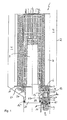
- a filter device 1 for filtering a liquid of an internal combustion engine, in particular in a motor vehicle, a filter housing 2 shown only schematically with a filter element 3, for example.
- a ring filter element disposed therein.
- the Filter element 3 separates in a known manner in the inserted state a bluff 4 of a clean room 5.
- the filter element 3 has an axially and eccentrically protruding pin 6, which is inserted in the inserted state in a pin receptacle 7 in an idle channel 8.
- the pin receptacle 7 can form an integral part of an insert 9, which is formed in particular from plastic.
- the insert 9 may be formed as part of a functional element 20 inserted into the filter housing 2.
- This functional element 20 has a ramp 26 which is shown in section, which ensures that, when the filter element 3 is mounted, the pin 6 is guided into the pin receptacle 7. This is necessary after an oil change, wherein the filter element 3 is replaced and the new filter element 3 is taken with the lid of the filter housing 2 until the pin 6 is seated in the pin receptacle 7.
- a valve device 10 is now provided in the area of the pin receptacle 7, which is pressed by the pin 6 into a closed state when the filter element 3 is present, closes the idling channel 8 and thereby, in the operating state of the filter device 1, drains the filter liquid from the raw space 4 into the idle channel 8 stops.
- the axially and eccentrically projecting from a lower end plate 11 of the filter element 3 pin 6 has a seal 12, via which the pin 6 is tightly inserted into the pin receptacle 7.
- the seal 12 may be formed, for example, as a simple O-ring seal and held in a corresponding, provided on the pin 6, circumferential groove.
- a connecting channel 13 is provided according to the invention, which opens in the idle direction 14 after the seal 12 of the pin 6 in the idle channel 8, so that when removed Filter element 3, both the raw space 4 and the clean room 5 via the open valve device 10th can be emptied, with an emptying of the clean room 5 via the connecting channel 13 takes place.
- the filter element 3 is slipped over a part 24 of the functional element 20, and is thereby also supported.
- This part 24 of the functional element 20 forms a portion of the clean room 5, which is emptied through the connecting channel 13 during removal of the filter element 3 in the idle channel 8.
- the valve device 10 comprises a sliding piston 15, two spring elements 16 and 17 and a valve piston 18, wherein the first spring element 16 between the valve piston 18 and the sliding piston 15 and the second spring element 17 between the valve piston 18 and the insert 9 is preferably made of plastic is.
- the second spring element 17 biases the valve piston 18 into its open position, whereas the first spring element 16 presses the valve piston 18 with the inserted filter element 3 into its closed position by actuation of the slide piston 15.
- the first Federlement 16 additionally serves together with the sliding piston 15 to compensate for tolerances from the filter element 3, z. B. from the pin 6 or from the production of the filter element 3, can result.
- the slide piston 15 is movably latched in the insert 9 in radially arranged windows 25, or openings, which also serve to drain the liquid from the blanks 4.
- Fig. 1 and 2 can be seen further, is the slide piston 15 with built-filter element 3 with the pin 6 of the filter element 3 in contact in the region of a valve 19.
- the valve 19 is formed by a sliding piston side valve seat, in which the pin 6 with a front side tight intervenes. With the filter element 3 removed, it is thus possible to pass through the open valve 19, that is, through the hollow slide piston 15, Filter liquid from the crude space 4 via the valve device 10 in the idle channel 8 drain.
- the mirror of the crude oil in the crude space 4 is laid down by the window 25 provided in the functional element 20 according to the invention, as a result of which more crude oil can leave the filter housing 2 via the idling channel 8 than was customary in the previously customary filters.
- windows 25 are provided underneath the seal 12 in the insert 9. These windows 25 simultaneously serve as a counter-latching means for the locking elements 23 of the sliding piston 15 designed as latching hooks.
- These windows 25 are also provided in an alternative embodiment, in which the sliding piston 15 attached to the pin 6, z. B. is locked.
- the sealing arrangement of the seals 12, 12 'and 12 "' is the same in the alternative embodiment.
- Fig. 1 and 2 is the filter element 3 shown in its installed state in which it is in contact with the pin 6 in contact with the sliding piston 15 and pushes it down.
- the first spring element 16 is pre-tensioned via the downwardly pushed sliding piston 15 and the associated valve piston 18 is pressed downwards, ie in its closed position, against a valve seat.
- the sliding piston 15 is in its upper initial position, whereby the first spring element 16 is relaxed.
- the second spring element 17 pushes the valve piston 18 upwards and lifts it from an insert-side valve seat.
- valve seat 27 forms the idle sealing point of the crude space 4 with respect to the idle channel 8 to the outside.
- the valve device 10 together with pin 6 and functional element 20 has six sealing points / seals 12, 12 ', 12 ", 12"', 28 and 27.
- the sealing point 28 is the valve seat 27 of the valve 19, which separates the clean room 5 from the raw space 4.
- the filtered oil is always present on the outside of the sliding piston 15 via the connection channel 13.
- the seals 12 'and 12 "form the seal of the functional element 20 in the filter housing 2.
- the seal of the valve seat 27 of the actual idle valve and its valve piston 18 seals the whole against the idling channel 8, and the environment.
- the Fig. 2 shows the sealing function of all important for the idling function seals in the case of the filter element 3 used or in the operation of the motor vehicle.
- the windows 25 are as long as possible so that the crude oil level is as low as possible. Particularly important is the sealing function of the seal 12 "', which prevents filtered oil flows back into the blanks 4.
- the various seals can be present both as an O-ring as well as molded seals ..
- the type of gaskets used can be chosen arbitrarily.
- the pin receptacle 7 of the insert 9 is liquid-tightly inserted via a seal 12 'in the idle channel 8, wherein the insert 9 is generally part of a Functional element 20 may be, which is liquid-tightly inserted via a corresponding nozzle 21 with a further seal 12 "in a clean-room side drain 22.
- the functional element 20 may be formed together with the insert 9 made of plastic, in particular as a plastic injection molded part to the pin 6 suitable ramp geometry
- the ramp must be designed so that the end face of the pin 6 engages in a slide piston side valve seat of the valve 19 is not violated, otherwise the sealing function can not be guaranteed
- the ramp must be designed so that the sliding piston 15 fastened to the journal 6 is not loosened or released, and if necessary a lubricious coating must be applied to the ramp. as well as for de n pin 6, and the sliding piston 15 are paid attention to the sliding properties.
- the geometry of the pin 6 itself must be adapted to the particular circumstances.
- the stability of the pin 6 must grow with increasing filter element size. Also, the thickness of the end plate 11 is mitangeformt on the pin 6 or to which it is attached, the weight of the filter element 3 must be adjusted to avoid that when installing a new filter element 3, the pin 6 is loosened or broken off.
- a seal 12 "' is also arranged on the sliding piston 15 in a corresponding circumferential groove, so that the sliding piston 15 is guided in a liquid-tight manner in the pin receptacle 7 or in a subsequent section of the idling channel 8 in the insert 9.
- the slide piston 15 may also be arranged on the journal 6 of the filter element 3.
- the filter device 1 according to the invention is designed for filtering lubricating oil or for filtering fuel.
- the filter device 1 according to the invention thus the pin 6 of the filter element 3 is used for actuating the valve device 10, but also has in addition via its seal 12 a sealing function.
- the two spring elements 16 and 17 in particular the manufacturing tolerances occurring during the production of the entire filter element 3 can be easily compensated.
- the filter device 1 according to the invention is used in particular in commercial vehicle construction, in which filter devices 1 with a large internal volume are common.
- 12 "'radial openings / windows 25 are provided in the region of the sliding piston 15 below the seal, through which filter liquid flowing from the raw space 4 to the valve device 10 can flow into an interior of the valve device 10
- the sliding piston 15 is pushed upwards by removing the filter element 3.
- the seal 12 "'retains its Sealing function. Due to the removal of the filter element 3, the spring force, which is now exerted by the second spring element 17 on the valve piston 18, also lifts it from its valve seat, so that filter fluid can flow away from the clean room 5 as well as from the raw space 4.
- the pin 6 can actuate an electrical circuit, which then actuates an electrically controlled valve located in the functional element 20.
- Fig. 3a, b show a filter device 1, which has a functional element 20 which has in the region of the pin receiving 7 above the seal 12 with inserted pin 6 more windows 25a, which allow a rapid and reliable emptying of the pin receptacle 7 before the pin 6 is pulled out. This can also prevent unwanted mixing of filtered and unfiltered fuel.
Abstract
Description
Die vorliegende Erfindung betrifft eine Filtereinrichtung zum Filtern einer Flüssigkeit einer Brennkraftmaschine, insbesondere in einem Kraftfahrzeug, mit den Merkmalen des Oberbegriffs des Anspruchs 1.The present invention relates to a filter device for filtering a fluid of an internal combustion engine, in particular in a motor vehicle, having the features of the preamble of
Aus der
Aus der
Aus der
Die vorliegende Erfindung beschäftigt sich mit dem Problem, für eine Filtereinrichtung der gattungsgemäßen Art, eine verbesserte oder zumindest eine andere Ausführungsform anzugeben, die insbesondere ein Austauschen eines Filterelements einfacher gestaltet und bei welcher weniger Roh- und Reinölvolumen beim Filterelementwechsel im Motor verbleibt.The present invention is concerned with the problem, for a filter device of the generic type, to provide an improved or at least another embodiment, which makes in particular a replacement of a filter element simpler and in which less crude and clean oil volume remains in the filter element change in the engine.
Dieses Problem wird erfindungsgemäß durch die Gegenstände der unabhängigen Ansprüche gelöst. Vorteilhafte Ausführungsformen sind Gegenstand der abhängigen Ansprüche.This problem is solved according to the invention by the subject matters of the independent claims. Advantageous embodiments are the subject of the dependent claims.
Die vorliegende Erfindung beruht auf dem allgemeinen Gedanken, bei einer Filtereinrichtung zum Filtern einer Flüssigkeit einer Brennkraftmaschine einen Verbindungskanal vorzusehen, der einerseits in einen Reinraum mündet und andererseits in einen Leerlaufkanal, wobei dieser Leerlaufkanal bei in die Filtereinrichtung eingesetztem Filterelement sowohl zum Rohraum hin als auch zu einem Ölreservoir über den Reinraum hin verschlossen ist, während er bei entferntem Filterelement geöffnet ist und gleichzeitig kommunizierend mit dem Reinraum und dem Rohraum verbunden ist, so dass nach einem Entfernen des Filterelements der Reinraum teilweise und der Rohraum vorzugsweise vollständig über den Leerlaufkanal entleert werden können. Die Filtereinrichtung weist darüber hinaus in bekannter Weise ein Filtergehäuse zur Aufnahme des Filterelements auf, wobei dieses Filterelement im eingesetzten Zustand den bekannten Rohraum von dem bekannten Reinraum trennt. Axial und exzentrisch abstehend ist an dem Filterelement ein Zapfen angeordnet, der im eingesteckten Zustand in eine Zapfenaufnahme im Leerlaufkanal eingesteckt ist. Ebenfalls im Bereich der Zapfenaufnahme ist darüber hinaus erfindungsgemäß eine Ventileinrichtung vorgesehen, die bei eingesetztem Filterelement durch den Zapfen in einen Schließzustand gedrückt wird und den Leerlaufkanal dadurch verschließt. Der bei eingesetztem Filterelement in die Zapfenaufnahme eingedrückte Zapfen weist eine Dichtung auf und ist somit dicht in den Leerlaufkanal einsteckbar. Durch das Betätigen der Ventileinrichtung durch das eingesteckte Filterelement kann weder Rohöl noch Reinöl über den Leerlaufkanal abfließen. Das Ventil und der Zapfen bilden mittels verschiedener Dichtungen die Abtrennung zwischen Roh- und Reinseite einerseits, sowie Roh- und Leerlauf- sowie Rein- und Leerlaufseite andererseits. Der erfindungsgemäß zwischen dem Reinraum und dem Leerlaufkanal vorgesehene Verbindungskanal, mündet in Leerlaufrichtung nach und damit stromab der Dichtung des Zapfens in den Leerlaufkanal, so dass bei entferntem Filterelement sowohl der Rohraum als auch der Reinraum über die geöffnete Ventileinrichtung und insbesondere durch einen hohlen Schiebekolben der Ventileinrichtung hindurch entleert werden können.The present invention is based on the general idea to provide in a filter device for filtering a liquid of an internal combustion engine, a connecting channel, which opens on the one hand in a clean room and on the other hand in an idle channel, said idle channel in inserted into the filter device filter element both to the raw space and to an oil reservoir is closed through the clean room, while it is open with the filter element removed and at the same time communicating with the clean room and the raw space is connected, so that after removal of the filter element of the clean room and the raw space can be preferably completely emptied through the idle channel. The filter device also has in known manner a filter housing for receiving the filter element, said filter element in the inserted state the known crude space separates from the known clean room. Axially and eccentrically projecting a pin is arranged on the filter element, which is inserted in the inserted state in a pin receptacle in the idle channel. Also in the field of pin receiving beyond a valve device according to the invention is provided, which is pressed with the filter element inserted through the pin in a closed state and thereby closes the idle channel. The indented with inserted filter element in the pin receptacle pin has a seal and is thus tightly inserted into the idle channel. By operating the valve device through the inserted filter element, neither crude oil nor clean oil can flow off via the idling channel. The valve and the pin form by means of various seals the separation between crude and clean side on the one hand, as well as raw and idle and clean and idle side on the other. The inventively provided between the clean room and the idle channel connecting channel opens in idle direction and thus downstream of the seal of the pin in the idle channel, so that with removed filter element both the raw space and the clean room on the open valve device and in particular by a hollow sliding piston valve device can be emptied through.
Bei eingestecktem Filterelement wird der Verbindungskanal nicht zur Ventileinrichtung hin verschlossen. Der Leerlaufkanal, ist bei eingestecktem Filterelement in beide Richtungen, dass heißt sowohl in Richtung des Rohraums als auch in Richtung des Ölreservoirs bzw. des Reinraumes verschlossen. Und zwar in Richtung des Rohraums sowohl durch die am Zapfen angeordnete Dichtung als auch durch eine Leerlaufdichtstelle der Ventileinrichtung und in Richtung des Ölreservoirs bzw. des Reinraumes durch eine weitere Dichtung der Ventileinrichtung. Mit der erfindungsgemäßen Filtereinrichtung, welche insbesondere bei Nutzfahrzeugen Anwendung findet, ist es möglich, Filterflüssigkeit sowohl aus dem Reinraum als auch aus dem Rohraum nach Entfernen des Filterelements über den Leerlaufkanal abzuführen.When the filter element is inserted, the connecting channel is not closed to the valve device. The idle channel, with plugged filter element in both directions, that is closed both in the direction of the raw space and in the direction of the oil reservoir or the clean room. Namely in the direction of the raw space both by the seal arranged on the journal and by an idle sealing point of the valve device and in the direction of the oil reservoir or the clean room by a further seal of the valve device. With the filter device according to the invention, which finds application in particular in commercial vehicles, it is possible Remove filter fluid from both the clean room and from the crude space after removal of the filter element via the idle channel.
Weitere wichtige Merkmale und Vorteile der Erfindung ergeben sich aus den Unteransprüchen, aus den Zeichnungen und aus der zugehörigen Figurenbeschreibung anhand der Zeichnungen.Other important features and advantages of the invention will become apparent from the dependent claims, from the drawings and from the associated figure description with reference to the drawings.
Es versteht sich, dass die vorstehend genannten und die nachstehend noch zu erläuternden Merkmale nicht nur in der jeweils angegebenen Kombination, sondern auch in anderen Kombinationen oder in Alleinstellung verwendbar sind, ohne den Rahmen der vorliegenden Erfindung zu verlassen.It is understood that the features mentioned above and those yet to be explained below can be used not only in the particular combination given, but also in other combinations or in isolation, without departing from the scope of the present invention.
Bevorzugte Ausführungsbeispiele der Erfindung sind in den Zeichnungen dargestellt und werden in der nachfolgenden Beschreibung näher erläutert, wobei sich gleiche Bezugszeichen auf gleiche oder ähnliche oder funktional gleiche Bauteile beziehen.Preferred embodiments of the invention are illustrated in the drawings and will be described in more detail in the following description, wherein like reference numerals refer to the same or similar or functionally identical components.
Dabei zeigen, jeweils schematisch,
- Fig. 1
- eine Schnittdarstellung durch eine erfindungsgemäße Filtereinrichtung,
- Fig. 2
- eine Darstellung wie in
Fig. 1 , jedoch im Bereich einer Ventileinrichtung, - Fig. 3
- eine Darstellung wie in
Fig. 2 , jedoch mit zusätzlichen Fenstern im Bereich der Ventileinrichtung.
- Fig. 1
- a sectional view through a filter device according to the invention,
- Fig. 2
- a representation like in
Fig. 1 but in the area of a valve device, - Fig. 3
- a representation like in
Fig. 2 , but with additional windows in the area of the valve device.
Entsprechend den
Das Filterelement 3 wird über einen Teil 24 des Funktionselements 20 gestülpt, und wird dadurch auch gestützt. Dieser Teil 24 des Funktionselements 20 bildet einen Abschnitt des Reinraumes 5, der durch den Verbindungskanal 13 beim Entfernen des Filterelementes 3 in den Leerlaufkanal 8 entleert wird.The
Generell umfasst die Ventileinrichtung 10 einen Schiebekolben 15, zwei Federelemente 16 und 17 sowie einen Ventilkolben 18, wobei das erste Federelement 16 zwischen dem Ventilkolben 18 und dem Schiebekolben 15 und das zweite Federelement 17 zwischen dem Ventilkolben 18 und dem vorzugsweise aus Kunststoff ausgebildeten Einsatz 9 angeordnet ist. Das zweite Federelement 17 spannt dabei den Ventilkolben 18 in seine Öffnungsstellung vor, wogegen das erste Federelement 16 durch Betätigung des Schiebekolbens 15 den Ventilkolben 18 bei eingesetztem Filterelement 3 in seine Schließstellung drückt. Das erste Federlement 16 dient zusätzlich zusammen mit dem Schiebekolben 15 zum Ausgleich von Toleranzen die vom Filterelement 3, z. B. vom Zapfen 6 oder von der Herstellung des Filterelements 3, herrühren können. Der Schiebekolben 15 ist im Einsatz 9 beweglich verrastet in radial angeordneten Fenstern 25, bzw. Öffnungen, die auch zum Abfluss der Flüssigkeit aus dem Rohraum 4 dienen.In general, the valve device 10 comprises a
Wie den
Durch die im erfindungsgemäßen Funktionselement 20 vorgesehenen Fenster 25 wird im Falle des Filterelementwechsels der Spiegel des Rohöles im Rohraum 4 nach unten verlegt, dadurch kann mehr Rohöl über den Leerlaufkanal 8 das Filtergehäuse 2 verlassen, als es bei den bisher üblichen Filtern üblich war.
Um auch im unteren Bereich des Filtergehäuses 2 den Rohraum 4 zu entleeren, sind im Einsatz 9 unterhalb der Dichtung 12"' Fenster 25 vorgesehen (nicht gezeigt). Diese Fenster 25 dienen gleichzeitig als Gegenrastmittel für die als Rasthaken ausgebildeten Sicherungselemente 23 des Schiebekolbens 15.In the case of the filter element change, the mirror of the crude oil in the
In order to empty the
Diese Fenster 25 sind auch bei einer alternativen Ausführungsform vorgesehen, bei der der Schiebekolben 15 am Zapfen 6 befestigt, z. B. verrastet ist. Die Dichtungsanordnung der Dichtungen 12, 12' und 12"' ist bei der alternativen Ausführungsform gleich.These
Gemäß den
Die
The
Die Fenster 25 sind möglichst lang damit der Rohölspiegel möglichst tief liegt. Wichtig ist insbesondere die Dichtfunktion der Dichtung 12"', die verhindert dass gefiltertes Öl in den Rohraum 4 zurückfließt. Die verschiedenen Dichtungen können sowohl als O-Ring als auch als angespritzte Dichtungen vorliegen. Die Art der verwendeten Dichtungen kann beliebig gewählt werden.The
Betrachtet man die
Die Geometrie des Zapfens 6 selber muss den jeweiligen Gegebenheiten angepasst werden. Bei der Verwendung der erfindungsgemäßen Filtereinrichtung 1 für Nutzfahrzeuge, muss man beachten, dass die Stabilität des Zapfens 6 mit zunehmender Filterelementgröße mitwachsen muss. Auch die Dicke der Endscheibe 11 an der der Zapfen 6 mitangeformt ist oder an der er befestigt ist, muss dem Gewicht des Filterelementes 3 angepasst werden, um zu vermeiden, dass beim Einbau eines neuen Filterelementes 3 der Zapfen 6 gelockert oder abgebrochen wird.Looking at the
The geometry of the
Desweiteren ist auch am Schiebekolben 15 in einer entsprechenden umlaufenden Nut eine Dichtung 12"' angeordnet, so dass der Schiebekolben 15 flüssigkeitsdicht in der Zapfenaufnahme 7 bzw. in einem sich daran anschließenden Abschnitt des Leerlaufkanals 8 im Einsatz 9 geführt ist. Selbstverständlich kann dabei rein theoretisch der Schiebekolben 15 auch am Zapfen 6 des Filterelements 3 angeordnet sein. In diesem Fall wären keine Sicherungselemente 23, wie beispielsweise Rasthaken, erforderlich, die durch Hintergreifen einer einsatzseitigen Rastkontur einen Verstellweg des Schiebekolbens 15 begrenzen.Furthermore, a
Generell ist die erfindungsgemäße Filtereinrichtung 1 zum Filtern von Schmieröl oder zum Filtern von Kraftstoff ausgebildet. Der erfindungsgemäßen Filtereinrichtung 1 wird somit der Zapfen 6 des Filterelements 3 zur Betätigung der Ventileinrichtung 10 benutzt, besitzt jedoch darüber hinaus über seine Dichtung 12 zusätzlich eine Dichtfunktion. Durch die beiden Federelemente 16 und 17 können darüber hinaus insbesondere die bei der Fertigung des gesamten Filterelementes 3 auftretenden Fertigungstoleranzen leicht kompensiert werden. Die erfindungsgemäße Filtereinrichtung 1 kommt insbesondere im Nutzfahrzeugbau zum Einsatz, in welchem Filtereinrichtungen 1 mit großem Innenvolumen üblich sind. Da bei derartigen Filtereinrichtungen 1 nicht nur rohseitig, sondern zugleich auch reinseitig viel Filterflüssigkeit ansteht, kann mit dem erfindungsgemäßen Einsatz 9 bzw. dem erfindungsgemäßen Funktionselement 20 eine kostengünstige und konstruktiv einfache Einrichtung geschaffen werden, die es gewährleistet, beim Austausch des Filterelements 3 den Rohraum 4 vollständig und den Reinraum 5 teilweise leer laufen zu lassen. Ohne die Dichtfunktion des Zapfens 6 und dem im Einsatz 9 bzw. im Funktionselement 20 vorgesehenen Verbindungskanal 13 zwischen dem Reinraum 5 und dem Leerlaufkanal 8, wäre ein teilweises Leerlaufen lassen des Reinraums 5 beim Ausbau des Filterelements 3 nicht möglich. Um ein Abfließen von Filterflüssigkeit aus dem Rohraum 4 zusätzlich zu erleichtern, sind im Bereich des Schiebekolbens 15 unterhalb der Dichtung 12"' Radialöffnungen / Fenster 25 vorgesehen, durch welche aus dem Rohraum 4 zur Ventileinrichtung 10 strömende Filterflüssigkeit in ein Inneres der Ventileinrichtung 10 hineinströmen kann. Durch das Entfernen des Filterelementes 3 wird der Schiebekolben 15 nach oben geschoben. Die Dichtung 12"' behält ihre Dichtfunktion. Durch das Entfernen des Filterelementes 3 wird aufgrund der nun von dem zweiten Federelement 17 auf den Ventilkolben 18 ausgeübten Federkraft auch dieser von seinem Ventilsitz abgehoben, so dass Filterflüssigkeit sowohl vom Reinraum 5 als auch vom Rohraum 4 abfließen kann.In general, the
In einer weiteren alternativen Ausführungsform, nicht gezeigt, kann der Zapfen 6 einen elektrischen Schaltkreis betätigen, der dann ein im Funktionselement 20 befindliches elektrisch gesteuertes Ventil betätigt.In a further alternative embodiment, not shown, the
Claims (13)
dadurch gekennzeichnet,
dass die Zapfenaufnahme (7), die Ventileinrichtung (10) und der Verbindungskanal (13) Bestandteil eines insbesondere aus Kunststoff ausgebildeten Einsatzes (9) sind.Filter device according to claim 1,
characterized,
in that the pin receptacle (7), the valve device (10) and the connecting channel (13) are part of an insert (9) formed in particular from plastic.
dadurch gekennzeichnet,
dass die Ventileinrichtung (10) einen Schiebekolben (15), Federelemente (16,17) und einen Ventilkolben (18) aufweist.Filter device according to claim 1 or 2,
characterized,
in that the valve device (10) has a slide piston (15), spring elements (16, 17) and a valve piston (18).
dadurch gekennzeichnet,
dass zwei Federelemente (16,17) vorgesehen sind, wovon das erste Federelement (16) zwischen dem Ventilkolben (18) und dem Schiebekolben (15) und das zweite Federelement (17) zwischen dem Ventilkolben (18) und dem Einsatz (9) angeordnet ist.Filter device according to claim 3,
characterized,
in that two spring elements (16, 17) are provided, of which the first spring element (16) is arranged between the valve piston (18) and the sliding piston (15) and the second spring element (17) is arranged between the valve piston (18) and the insert (9) is.
dadurch gekennzeichnet,
dass das zweite Federelement (17) den Ventilkolben (18) in seine Öffnungsstellung vorspannt, wogegen das erste Federelement (16) den Ventilkolben (18) bei eingesetztem Filterelement (3) in seine Schließstellung drückt.Filter device according to claim 4,
characterized,
that the second spring element (17) biases the valve piston (18) in its open position, whereas the first spring element (16) presses the valve piston (18) with its inserted filter element (3) in its closed position.
dadurch gekennzeichnet,
dass der Schiebekolben (15) bei eingebautem Filterelement (3) mit dem Zapfen (6) des Filterelements (3) in Kontakt steht.Filter device according to one of claims 3 to 5,
characterized,
that the sliding piston (15) is in contact with the pin (6) of the filter element (3) when the filter element (3) is installed.
dadurch gekennzeichnet,
dass der Einsatz (9) über eine O-Ringdichtung (12') flüssigkeitsdicht in den Leerlaufkanal (8) einsetzbar ist, wobei der Einsatz (9) zugleich Bestandteil eines Funktionselementes (20) ist.Filter device according to one of claims 2 to 6,
characterized,
that the insert (9) via an O-ring seal (12 ') fluid-tightly inserted into the idle channel (8), wherein the insert (9) is also part of a functional element (20).
dadurch gekennzeichnet,
dass der Schiebekolben (15) am Zapfen (6) des Filterelementes (3) angeordnet ist.Filter device according to one of claims 3 to 7,
characterized,
that the sliding piston (15) is arranged on the pin (6) of the filter element (3).
dadurch gekennzeichnet,
dass die Filtereinrichtung (1) zum Filtern von Schmieröl oder zum Filtern von Kraftstoff ausgestaltet ist.Filter device according to one of claims 1 to 8,
characterized,
in that the filter device (1) is designed to filter lubricating oil or to filter fuel.
dadurch gekennzeichnet,
dass der Schiebekolben (15) eine außen liegende Dichtung (12"') aufweist, über welche er gegenüber der Zapfenaufnahme (7) abgedichtet ist.Filter device according to one of claims 3 to 9,
characterized,
in that the sliding piston (15) has an outer seal (12 "'), by means of which it is sealed relative to the pin receptacle (7).
dadurch gekennzeichnet,
dass der Schiebekolben (15) einen dem Zapfen (6) zugewandten axialen Ventilsitz aufweist, an/in welchen der Zapfen (6) des Filterelements (3) mit seiner Stirnseite dicht eingreift.Filter device according to one of claims 3 to 10,
characterized,
that the sliding piston (15) facing the one pin (6) axial valve seat, tightly engaged on / in which the pin (6) of the filter element (3) with its end face.
dadurch gekennzeichnet,
dass der Schiebekolben (15) hohl ausgebildet ist.Filter device according to one of claims 3 to 11,
characterized,
that the sliding piston (15) is hollow.
Applications Claiming Priority (1)
| Application Number | Priority Date | Filing Date | Title |
|---|---|---|---|
| DE102009023027A DE102009023027A1 (en) | 2009-05-28 | 2009-05-28 | filtering device |
Publications (2)
| Publication Number | Publication Date |
|---|---|
| EP2263773A1 true EP2263773A1 (en) | 2010-12-22 |
| EP2263773B1 EP2263773B1 (en) | 2013-03-13 |
Family
ID=42651111
Family Applications (1)
| Application Number | Title | Priority Date | Filing Date |
|---|---|---|---|
| EP10163057A Not-in-force EP2263773B1 (en) | 2009-05-28 | 2010-05-18 | Filter device |
Country Status (3)
| Country | Link |
|---|---|
| EP (1) | EP2263773B1 (en) |
| KR (1) | KR101626991B1 (en) |
| DE (1) | DE102009023027A1 (en) |
Families Citing this family (5)
| Publication number | Priority date | Publication date | Assignee | Title |
|---|---|---|---|---|
| DE102013216807A1 (en) * | 2013-08-23 | 2015-02-26 | Robert Bosch Gmbh | Filter device with a connection of a filter element |
| DE102013216845A1 (en) * | 2013-08-23 | 2015-02-26 | Robert Bosch Gmbh | Filter device with a valve between filter housing and filter element |
| DE102015218184A1 (en) * | 2015-09-22 | 2017-03-23 | Mahle International Gmbh | filtering device |
| EP3608009A1 (en) | 2018-08-10 | 2020-02-12 | Mann+Hummel GmbH | Filter system and filter element with improved positioning means |
| DE102020207220A1 (en) | 2020-06-09 | 2021-12-09 | Mahle International Gmbh | Filter device for cleaning an oil and filter element |
Citations (7)
| Publication number | Priority date | Publication date | Assignee | Title |
|---|---|---|---|---|
| DE19702612A1 (en) * | 1997-01-24 | 1998-07-30 | Mann & Hummel Filter | Drain valve |
| WO2001012294A1 (en) | 1999-08-12 | 2001-02-22 | Purolator Products Na, Inc. | Center tube with built in snap for automotive oil filter |
| WO2002036940A1 (en) * | 2000-10-31 | 2002-05-10 | Arvin Technologies, Inc | Oil filter with integrated cooler |
| US6572768B1 (en) * | 2002-03-25 | 2003-06-03 | Arvin Technologies, Inc. | Oil filter apparatus |
| EP1229985B1 (en) | 1999-10-23 | 2003-08-27 | MAHLE Filtersysteme GmbH | Liquid filter, especially an oil filter |
| WO2003078025A1 (en) * | 2002-03-15 | 2003-09-25 | Arvin Technologies, Inc. | Oilfilter assembly |
| DE202006007194U1 (en) * | 2006-05-05 | 2007-09-13 | Hengst Gmbh & Co.Kg | Coolant filter with silicate storage |
Family Cites Families (3)
| Publication number | Priority date | Publication date | Assignee | Title |
|---|---|---|---|---|
| DE3422482A1 (en) * | 1984-06-16 | 1985-12-19 | Filterwerk Mann & Hummel Gmbh, 7140 Ludwigsburg | LIQUID FILTER FOR THE LUBRICANT OR FUEL OF AN INTERNAL COMBUSTION ENGINE |
| DE4439815C2 (en) * | 1994-11-08 | 2001-06-07 | Mann & Hummel Filter | Filters, in particular liquid filters |
| DE10302934A1 (en) * | 2003-01-24 | 2004-07-29 | Mann + Hummel Gmbh | Filter housing, e.g. for oil filter, contains filter element which divides housing into inner and outer regions, and heat exchanger |
-
2009
- 2009-05-28 DE DE102009023027A patent/DE102009023027A1/en not_active Withdrawn
-
2010
- 2010-05-18 EP EP10163057A patent/EP2263773B1/en not_active Not-in-force
- 2010-05-27 KR KR1020100049667A patent/KR101626991B1/en active IP Right Grant
Patent Citations (8)
| Publication number | Priority date | Publication date | Assignee | Title |
|---|---|---|---|---|
| DE19702612A1 (en) * | 1997-01-24 | 1998-07-30 | Mann & Hummel Filter | Drain valve |
| WO1998032517A1 (en) | 1997-01-24 | 1998-07-30 | Filterwerk Mann + Hummel Gmbh | Drain valve |
| WO2001012294A1 (en) | 1999-08-12 | 2001-02-22 | Purolator Products Na, Inc. | Center tube with built in snap for automotive oil filter |
| EP1229985B1 (en) | 1999-10-23 | 2003-08-27 | MAHLE Filtersysteme GmbH | Liquid filter, especially an oil filter |
| WO2002036940A1 (en) * | 2000-10-31 | 2002-05-10 | Arvin Technologies, Inc | Oil filter with integrated cooler |
| WO2003078025A1 (en) * | 2002-03-15 | 2003-09-25 | Arvin Technologies, Inc. | Oilfilter assembly |
| US6572768B1 (en) * | 2002-03-25 | 2003-06-03 | Arvin Technologies, Inc. | Oil filter apparatus |
| DE202006007194U1 (en) * | 2006-05-05 | 2007-09-13 | Hengst Gmbh & Co.Kg | Coolant filter with silicate storage |
Also Published As
| Publication number | Publication date |
|---|---|
| DE102009023027A1 (en) | 2010-12-02 |
| EP2263773B1 (en) | 2013-03-13 |
| KR101626991B1 (en) | 2016-06-03 |
| KR20100129205A (en) | 2010-12-08 |
Similar Documents
| Publication | Publication Date | Title |
|---|---|---|
| EP1137470B1 (en) | Fluid filter with a discharge dome that is fixed to the housing | |
| EP3329979B1 (en) | Filter housing and filter insert | |
| EP2654918B1 (en) | Liquid filter having a filter bypass valve and filter insert therefor | |
| EP2649292B1 (en) | Fuel filter | |
| DE10064482B4 (en) | Filter arrangement for liquids | |
| EP2445605B1 (en) | Filter device | |
| DE202005007872U1 (en) | Filter device, in particular for liquid filtration in internal combustion engines | |
| DE202005007869U1 (en) | Filter device, in particular for liquid filtration in internal combustion engines | |
| EP2263773B1 (en) | Filter device | |
| EP2854986A1 (en) | Filter device | |
| EP1222010B1 (en) | Liquid filter, especially an oil filter | |
| WO2020126186A1 (en) | Oil filter for a motor vehicle and filter cartridge for an oil filter | |
| DE102008049006A1 (en) | liquid filters | |
| EP1648583A1 (en) | Oil filter arrangement and filter element | |
| EP2337618B1 (en) | Filter device | |
| EP2808071B1 (en) | Filter device, in particular for an automotive car | |
| EP2314364A1 (en) | Filter device | |
| EP2263772B1 (en) | Filter device | |
| DE102010049975A1 (en) | filter means | |
| EP2783738B1 (en) | Filtering device | |
| DE102016203764A1 (en) | filtering device | |
| DE102015222425A1 (en) | Spin-on easy-change filter | |
| DE102018204255A1 (en) | filtering device | |
| WO2018065138A1 (en) | Liquid filter | |
| EP2608864B1 (en) | Filter and method for producing same |
Legal Events
| Date | Code | Title | Description |
|---|---|---|---|
| PUAI | Public reference made under article 153(3) epc to a published international application that has entered the european phase |
Free format text: ORIGINAL CODE: 0009012 |
|
| AK | Designated contracting states |
Kind code of ref document: A1 Designated state(s): AL AT BE BG CH CY CZ DE DK EE ES FI FR GB GR HR HU IE IS IT LI LT LU LV MC MK MT NL NO PL PT RO SE SI SK SM TR |
|
| AX | Request for extension of the european patent |
Extension state: BA ME RS |
|
| 17P | Request for examination filed |
Effective date: 20110528 |
|
| GRAP | Despatch of communication of intention to grant a patent |
Free format text: ORIGINAL CODE: EPIDOSNIGR1 |
|
| RIC1 | Information provided on ipc code assigned before grant |
Ipc: B01D 35/153 20060101AFI20120917BHEP |
|
| GRAS | Grant fee paid |
Free format text: ORIGINAL CODE: EPIDOSNIGR3 |
|
| GRAA | (expected) grant |
Free format text: ORIGINAL CODE: 0009210 |
|
| AK | Designated contracting states |
Kind code of ref document: B1 Designated state(s): AL AT BE BG CH CY CZ DE DK EE ES FI FR GB GR HR HU IE IS IT LI LT LU LV MC MK MT NL NO PL PT RO SE SI SK SM TR |
|
| REG | Reference to a national code |
Ref country code: GB Ref legal event code: FG4D Free format text: NOT ENGLISH |
|
| REG | Reference to a national code |
Ref country code: AT Ref legal event code: REF Ref document number: 600443 Country of ref document: AT Kind code of ref document: T Effective date: 20130315 Ref country code: CH Ref legal event code: EP |
|
| REG | Reference to a national code |
Ref country code: IE Ref legal event code: FG4D Free format text: LANGUAGE OF EP DOCUMENT: GERMAN |
|
| REG | Reference to a national code |
Ref country code: DE Ref legal event code: R096 Ref document number: 502010002513 Country of ref document: DE Effective date: 20130508 |
|
| PG25 | Lapsed in a contracting state [announced via postgrant information from national office to epo] |
Ref country code: ES Free format text: LAPSE BECAUSE OF FAILURE TO SUBMIT A TRANSLATION OF THE DESCRIPTION OR TO PAY THE FEE WITHIN THE PRESCRIBED TIME-LIMIT Effective date: 20130624 Ref country code: LT Free format text: LAPSE BECAUSE OF FAILURE TO SUBMIT A TRANSLATION OF THE DESCRIPTION OR TO PAY THE FEE WITHIN THE PRESCRIBED TIME-LIMIT Effective date: 20130313 Ref country code: SE Free format text: LAPSE BECAUSE OF FAILURE TO SUBMIT A TRANSLATION OF THE DESCRIPTION OR TO PAY THE FEE WITHIN THE PRESCRIBED TIME-LIMIT Effective date: 20130313 Ref country code: BG Free format text: LAPSE BECAUSE OF FAILURE TO SUBMIT A TRANSLATION OF THE DESCRIPTION OR TO PAY THE FEE WITHIN THE PRESCRIBED TIME-LIMIT Effective date: 20130613 Ref country code: NO Free format text: LAPSE BECAUSE OF FAILURE TO SUBMIT A TRANSLATION OF THE DESCRIPTION OR TO PAY THE FEE WITHIN THE PRESCRIBED TIME-LIMIT Effective date: 20130613 |
|
| REG | Reference to a national code |
Ref country code: NL Ref legal event code: VDEP Effective date: 20130313 |
|
| REG | Reference to a national code |
Ref country code: LT Ref legal event code: MG4D |
|
| PG25 | Lapsed in a contracting state [announced via postgrant information from national office to epo] |
Ref country code: SI Free format text: LAPSE BECAUSE OF FAILURE TO SUBMIT A TRANSLATION OF THE DESCRIPTION OR TO PAY THE FEE WITHIN THE PRESCRIBED TIME-LIMIT Effective date: 20130313 Ref country code: GR Free format text: LAPSE BECAUSE OF FAILURE TO SUBMIT A TRANSLATION OF THE DESCRIPTION OR TO PAY THE FEE WITHIN THE PRESCRIBED TIME-LIMIT Effective date: 20130614 Ref country code: FI Free format text: LAPSE BECAUSE OF FAILURE TO SUBMIT A TRANSLATION OF THE DESCRIPTION OR TO PAY THE FEE WITHIN THE PRESCRIBED TIME-LIMIT Effective date: 20130313 Ref country code: LV Free format text: LAPSE BECAUSE OF FAILURE TO SUBMIT A TRANSLATION OF THE DESCRIPTION OR TO PAY THE FEE WITHIN THE PRESCRIBED TIME-LIMIT Effective date: 20130313 |
|
| PG25 | Lapsed in a contracting state [announced via postgrant information from national office to epo] |
Ref country code: HR Free format text: LAPSE BECAUSE OF FAILURE TO SUBMIT A TRANSLATION OF THE DESCRIPTION OR TO PAY THE FEE WITHIN THE PRESCRIBED TIME-LIMIT Effective date: 20130313 |
|
| PG25 | Lapsed in a contracting state [announced via postgrant information from national office to epo] |
Ref country code: NL Free format text: LAPSE BECAUSE OF FAILURE TO SUBMIT A TRANSLATION OF THE DESCRIPTION OR TO PAY THE FEE WITHIN THE PRESCRIBED TIME-LIMIT Effective date: 20130313 Ref country code: EE Free format text: LAPSE BECAUSE OF FAILURE TO SUBMIT A TRANSLATION OF THE DESCRIPTION OR TO PAY THE FEE WITHIN THE PRESCRIBED TIME-LIMIT Effective date: 20130313 Ref country code: SK Free format text: LAPSE BECAUSE OF FAILURE TO SUBMIT A TRANSLATION OF THE DESCRIPTION OR TO PAY THE FEE WITHIN THE PRESCRIBED TIME-LIMIT Effective date: 20130313 Ref country code: RO Free format text: LAPSE BECAUSE OF FAILURE TO SUBMIT A TRANSLATION OF THE DESCRIPTION OR TO PAY THE FEE WITHIN THE PRESCRIBED TIME-LIMIT Effective date: 20130313 Ref country code: CZ Free format text: LAPSE BECAUSE OF FAILURE TO SUBMIT A TRANSLATION OF THE DESCRIPTION OR TO PAY THE FEE WITHIN THE PRESCRIBED TIME-LIMIT Effective date: 20130313 Ref country code: IS Free format text: LAPSE BECAUSE OF FAILURE TO SUBMIT A TRANSLATION OF THE DESCRIPTION OR TO PAY THE FEE WITHIN THE PRESCRIBED TIME-LIMIT Effective date: 20130713 Ref country code: PT Free format text: LAPSE BECAUSE OF FAILURE TO SUBMIT A TRANSLATION OF THE DESCRIPTION OR TO PAY THE FEE WITHIN THE PRESCRIBED TIME-LIMIT Effective date: 20130715 |
|
| PG25 | Lapsed in a contracting state [announced via postgrant information from national office to epo] |
Ref country code: PL Free format text: LAPSE BECAUSE OF FAILURE TO SUBMIT A TRANSLATION OF THE DESCRIPTION OR TO PAY THE FEE WITHIN THE PRESCRIBED TIME-LIMIT Effective date: 20130313 |
|
| BERE | Be: lapsed |
Owner name: MAHLE INTERNATIONAL G.M.B.H. Effective date: 20130531 |
|
| PG25 | Lapsed in a contracting state [announced via postgrant information from national office to epo] |
Ref country code: MC Free format text: LAPSE BECAUSE OF FAILURE TO SUBMIT A TRANSLATION OF THE DESCRIPTION OR TO PAY THE FEE WITHIN THE PRESCRIBED TIME-LIMIT Effective date: 20130313 |
|
| PLBE | No opposition filed within time limit |
Free format text: ORIGINAL CODE: 0009261 |
|
| STAA | Information on the status of an ep patent application or granted ep patent |
Free format text: STATUS: NO OPPOSITION FILED WITHIN TIME LIMIT |
|
| PG25 | Lapsed in a contracting state [announced via postgrant information from national office to epo] |
Ref country code: DK Free format text: LAPSE BECAUSE OF FAILURE TO SUBMIT A TRANSLATION OF THE DESCRIPTION OR TO PAY THE FEE WITHIN THE PRESCRIBED TIME-LIMIT Effective date: 20130313 |
|
| 26N | No opposition filed |
Effective date: 20131216 |
|
| REG | Reference to a national code |
Ref country code: IE Ref legal event code: MM4A |
|
| PG25 | Lapsed in a contracting state [announced via postgrant information from national office to epo] |
Ref country code: BE Free format text: LAPSE BECAUSE OF NON-PAYMENT OF DUE FEES Effective date: 20130531 Ref country code: IT Free format text: LAPSE BECAUSE OF FAILURE TO SUBMIT A TRANSLATION OF THE DESCRIPTION OR TO PAY THE FEE WITHIN THE PRESCRIBED TIME-LIMIT Effective date: 20130313 |
|
| REG | Reference to a national code |
Ref country code: DE Ref legal event code: R097 Ref document number: 502010002513 Country of ref document: DE Effective date: 20131216 |
|
| PG25 | Lapsed in a contracting state [announced via postgrant information from national office to epo] |
Ref country code: IE Free format text: LAPSE BECAUSE OF NON-PAYMENT OF DUE FEES Effective date: 20130518 |
|
| REG | Reference to a national code |
Ref country code: CH Ref legal event code: PL |
|
| PG25 | Lapsed in a contracting state [announced via postgrant information from national office to epo] |
Ref country code: CH Free format text: LAPSE BECAUSE OF NON-PAYMENT OF DUE FEES Effective date: 20140531 Ref country code: LI Free format text: LAPSE BECAUSE OF NON-PAYMENT OF DUE FEES Effective date: 20140531 |
|
| PG25 | Lapsed in a contracting state [announced via postgrant information from national office to epo] |
Ref country code: MT Free format text: LAPSE BECAUSE OF FAILURE TO SUBMIT A TRANSLATION OF THE DESCRIPTION OR TO PAY THE FEE WITHIN THE PRESCRIBED TIME-LIMIT Effective date: 20130313 |
|
| PG25 | Lapsed in a contracting state [announced via postgrant information from national office to epo] |
Ref country code: SM Free format text: LAPSE BECAUSE OF FAILURE TO SUBMIT A TRANSLATION OF THE DESCRIPTION OR TO PAY THE FEE WITHIN THE PRESCRIBED TIME-LIMIT Effective date: 20130313 |
|
| PG25 | Lapsed in a contracting state [announced via postgrant information from national office to epo] |
Ref country code: TR Free format text: LAPSE BECAUSE OF FAILURE TO SUBMIT A TRANSLATION OF THE DESCRIPTION OR TO PAY THE FEE WITHIN THE PRESCRIBED TIME-LIMIT Effective date: 20130313 Ref country code: CY Free format text: LAPSE BECAUSE OF FAILURE TO SUBMIT A TRANSLATION OF THE DESCRIPTION OR TO PAY THE FEE WITHIN THE PRESCRIBED TIME-LIMIT Effective date: 20130313 |
|
| PG25 | Lapsed in a contracting state [announced via postgrant information from national office to epo] |
Ref country code: HU Free format text: LAPSE BECAUSE OF FAILURE TO SUBMIT A TRANSLATION OF THE DESCRIPTION OR TO PAY THE FEE WITHIN THE PRESCRIBED TIME-LIMIT; INVALID AB INITIO Effective date: 20100518 Ref country code: MK Free format text: LAPSE BECAUSE OF FAILURE TO SUBMIT A TRANSLATION OF THE DESCRIPTION OR TO PAY THE FEE WITHIN THE PRESCRIBED TIME-LIMIT Effective date: 20130313 Ref country code: LU Free format text: LAPSE BECAUSE OF NON-PAYMENT OF DUE FEES Effective date: 20130518 |
|
| REG | Reference to a national code |
Ref country code: FR Ref legal event code: PLFP Year of fee payment: 7 |
|
| REG | Reference to a national code |
Ref country code: AT Ref legal event code: MM01 Ref document number: 600443 Country of ref document: AT Kind code of ref document: T Effective date: 20150518 |
|
| PG25 | Lapsed in a contracting state [announced via postgrant information from national office to epo] |
Ref country code: AT Free format text: LAPSE BECAUSE OF NON-PAYMENT OF DUE FEES Effective date: 20150518 |
|
| REG | Reference to a national code |
Ref country code: FR Ref legal event code: PLFP Year of fee payment: 8 |
|
| REG | Reference to a national code |
Ref country code: FR Ref legal event code: PLFP Year of fee payment: 9 |
|
| PG25 | Lapsed in a contracting state [announced via postgrant information from national office to epo] |
Ref country code: AL Free format text: LAPSE BECAUSE OF FAILURE TO SUBMIT A TRANSLATION OF THE DESCRIPTION OR TO PAY THE FEE WITHIN THE PRESCRIBED TIME-LIMIT Effective date: 20130313 |
|
| PGFP | Annual fee paid to national office [announced via postgrant information from national office to epo] |
Ref country code: FR Payment date: 20190528 Year of fee payment: 10 |
|
| PGFP | Annual fee paid to national office [announced via postgrant information from national office to epo] |
Ref country code: GB Payment date: 20190529 Year of fee payment: 10 Ref country code: DE Payment date: 20190731 Year of fee payment: 10 |
|
| REG | Reference to a national code |
Ref country code: DE Ref legal event code: R119 Ref document number: 502010002513 Country of ref document: DE |
|
| GBPC | Gb: european patent ceased through non-payment of renewal fee |
Effective date: 20200518 |
|
| PG25 | Lapsed in a contracting state [announced via postgrant information from national office to epo] |
Ref country code: FR Free format text: LAPSE BECAUSE OF NON-PAYMENT OF DUE FEES Effective date: 20200531 Ref country code: GB Free format text: LAPSE BECAUSE OF NON-PAYMENT OF DUE FEES Effective date: 20200518 |
|
| PG25 | Lapsed in a contracting state [announced via postgrant information from national office to epo] |
Ref country code: DE Free format text: LAPSE BECAUSE OF NON-PAYMENT OF DUE FEES Effective date: 20201201 |