EP2263773A1 - Dispositif de filtre - Google Patents
Dispositif de filtre Download PDFInfo
- Publication number
- EP2263773A1 EP2263773A1 EP10163057A EP10163057A EP2263773A1 EP 2263773 A1 EP2263773 A1 EP 2263773A1 EP 10163057 A EP10163057 A EP 10163057A EP 10163057 A EP10163057 A EP 10163057A EP 2263773 A1 EP2263773 A1 EP 2263773A1
- Authority
- EP
- European Patent Office
- Prior art keywords
- pin
- filter
- filter element
- valve
- filter device
- Prior art date
- Legal status (The legal status is an assumption and is not a legal conclusion. Google has not performed a legal analysis and makes no representation as to the accuracy of the status listed.)
- Granted
Links
- 239000007788 liquid Substances 0.000 claims description 10
- 238000001914 filtration Methods 0.000 claims description 6
- 238000002485 combustion reaction Methods 0.000 claims description 5
- 239000000446 fuel Substances 0.000 claims description 3
- 239000010687 lubricating oil Substances 0.000 claims description 3
- 238000007789 sealing Methods 0.000 description 11
- 239000003921 oil Substances 0.000 description 10
- 239000010779 crude oil Substances 0.000 description 5
- 239000012530 fluid Substances 0.000 description 3
- 238000004519 manufacturing process Methods 0.000 description 3
- 230000001419 dependent effect Effects 0.000 description 2
- 238000004140 cleaning Methods 0.000 description 1
- 239000011248 coating agent Substances 0.000 description 1
- 238000000576 coating method Methods 0.000 description 1
- 238000010276 construction Methods 0.000 description 1
- 238000002347 injection Methods 0.000 description 1
- 239000007924 injection Substances 0.000 description 1
- 238000009434 installation Methods 0.000 description 1
- 238000002955 isolation Methods 0.000 description 1
- 238000002156 mixing Methods 0.000 description 1
- 238000000926 separation method Methods 0.000 description 1
Images

Classifications
-
- B—PERFORMING OPERATIONS; TRANSPORTING
- B01—PHYSICAL OR CHEMICAL PROCESSES OR APPARATUS IN GENERAL
- B01D—SEPARATION
- B01D35/00—Filtering devices having features not specifically covered by groups B01D24/00 - B01D33/00, or for applications not specifically covered by groups B01D24/00 - B01D33/00; Auxiliary devices for filtration; Filter housing constructions
- B01D35/14—Safety devices specially adapted for filtration; Devices for indicating clogging
- B01D35/153—Anti-leakage or anti-return valves
-
- B—PERFORMING OPERATIONS; TRANSPORTING
- B01—PHYSICAL OR CHEMICAL PROCESSES OR APPARATUS IN GENERAL
- B01D—SEPARATION
- B01D35/00—Filtering devices having features not specifically covered by groups B01D24/00 - B01D33/00, or for applications not specifically covered by groups B01D24/00 - B01D33/00; Auxiliary devices for filtration; Filter housing constructions
- B01D35/16—Cleaning-out devices, e.g. for removing the cake from the filter casing or for evacuating the last remnants of liquid
-
- B—PERFORMING OPERATIONS; TRANSPORTING
- B01—PHYSICAL OR CHEMICAL PROCESSES OR APPARATUS IN GENERAL
- B01D—SEPARATION
- B01D2201/00—Details relating to filtering apparatus
- B01D2201/04—Supports for the filtering elements
- B01D2201/0415—Details of supporting structures
-
- B—PERFORMING OPERATIONS; TRANSPORTING
- B01—PHYSICAL OR CHEMICAL PROCESSES OR APPARATUS IN GENERAL
- B01D—SEPARATION
- B01D2201/00—Details relating to filtering apparatus
- B01D2201/29—Filter cartridge constructions
- B01D2201/291—End caps
-
- B—PERFORMING OPERATIONS; TRANSPORTING
- B01—PHYSICAL OR CHEMICAL PROCESSES OR APPARATUS IN GENERAL
- B01D—SEPARATION
- B01D2201/00—Details relating to filtering apparatus
- B01D2201/30—Filter housing constructions
- B01D2201/301—Details of removable closures, lids, caps, filter heads
- B01D2201/305—Snap, latch or clip connecting means
-
- B—PERFORMING OPERATIONS; TRANSPORTING
- B01—PHYSICAL OR CHEMICAL PROCESSES OR APPARATUS IN GENERAL
- B01D—SEPARATION
- B01D2201/00—Details relating to filtering apparatus
- B01D2201/34—Seals or gaskets for filtering elements
Definitions
- the present invention relates to a filter device for filtering a fluid of an internal combustion engine, in particular in a motor vehicle, having the features of the preamble of claim 1.
- Such a filter device is known, which is preferably an oil filter for cleaning lubricating oil, in particular for internal combustion engines of motor vehicles.
- the known filter device has a filter housing for receiving a filter element, wherein the filter housing has a raw-side inlet and a clean-side drain. When inserted, the filter element separates a raw space communicating with the feed from a clean space communicating with the feed.
- the filter housing of the known filter device has a communicating with the raw space idle, which forms for a formed on the filter element, axially and eccentrically protruding pin a pin receiving, in which the pin is inserted in the inserted state of the filter element. The pin thus closes the idle when the filter element is properly inserted into the filter housing.
- a drain valve in particular for an oil filter, known, in which a valve body for closing a drain opening is pressed spring-loaded against a valve seat at the drain opening of a liquid container.
- the valve body has at least one barb, which during the assembly of the drain valve through the drain opening can be snapped against the pressure of a spring and thus a predetermined by the shape of the barb distance of Valve body fixed to the valve seat in the open state.
- the present invention is concerned with the problem, for a filter device of the generic type, to provide an improved or at least another embodiment, which makes in particular a replacement of a filter element simpler and in which less crude and clean oil volume remains in the filter element change in the engine.
- the present invention is based on the general idea to provide in a filter device for filtering a liquid of an internal combustion engine, a connecting channel, which opens on the one hand in a clean room and on the other hand in an idle channel, said idle channel in inserted into the filter device filter element both to the raw space and to an oil reservoir is closed through the clean room, while it is open with the filter element removed and at the same time communicating with the clean room and the raw space is connected, so that after removal of the filter element of the clean room and the raw space can be preferably completely emptied through the idle channel.
- the filter device also has in known manner a filter housing for receiving the filter element, said filter element in the inserted state the known crude space separates from the known clean room.
- Axially and eccentrically projecting a pin is arranged on the filter element, which is inserted in the inserted state in a pin receptacle in the idle channel. Also in the field of pin receiving beyond a valve device according to the invention is provided, which is pressed with the filter element inserted through the pin in a closed state and thereby closes the idle channel.
- the indented with inserted filter element in the pin receptacle pin has a seal and is thus tightly inserted into the idle channel.
- the inventively provided between the clean room and the idle channel connecting channel opens in idle direction and thus downstream of the seal of the pin in the idle channel, so that with removed filter element both the raw space and the clean room on the open valve device and in particular by a hollow sliding piston valve device can be emptied through.
- the connecting channel is not closed to the valve device.
- the idle channel with plugged filter element in both directions, that is closed both in the direction of the raw space and in the direction of the oil reservoir or the clean room. Namely in the direction of the raw space both by the seal arranged on the journal and by an idle sealing point of the valve device and in the direction of the oil reservoir or the clean room by a further seal of the valve device.
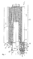
- a filter device 1 for filtering a liquid of an internal combustion engine, in particular in a motor vehicle, a filter housing 2 shown only schematically with a filter element 3, for example.
- a ring filter element disposed therein.
- the Filter element 3 separates in a known manner in the inserted state a bluff 4 of a clean room 5.
- the filter element 3 has an axially and eccentrically protruding pin 6, which is inserted in the inserted state in a pin receptacle 7 in an idle channel 8.
- the pin receptacle 7 can form an integral part of an insert 9, which is formed in particular from plastic.
- the insert 9 may be formed as part of a functional element 20 inserted into the filter housing 2.
- This functional element 20 has a ramp 26 which is shown in section, which ensures that, when the filter element 3 is mounted, the pin 6 is guided into the pin receptacle 7. This is necessary after an oil change, wherein the filter element 3 is replaced and the new filter element 3 is taken with the lid of the filter housing 2 until the pin 6 is seated in the pin receptacle 7.
- a valve device 10 is now provided in the area of the pin receptacle 7, which is pressed by the pin 6 into a closed state when the filter element 3 is present, closes the idling channel 8 and thereby, in the operating state of the filter device 1, drains the filter liquid from the raw space 4 into the idle channel 8 stops.
- the axially and eccentrically projecting from a lower end plate 11 of the filter element 3 pin 6 has a seal 12, via which the pin 6 is tightly inserted into the pin receptacle 7.
- the seal 12 may be formed, for example, as a simple O-ring seal and held in a corresponding, provided on the pin 6, circumferential groove.
- a connecting channel 13 is provided according to the invention, which opens in the idle direction 14 after the seal 12 of the pin 6 in the idle channel 8, so that when removed Filter element 3, both the raw space 4 and the clean room 5 via the open valve device 10th can be emptied, with an emptying of the clean room 5 via the connecting channel 13 takes place.
- the filter element 3 is slipped over a part 24 of the functional element 20, and is thereby also supported.
- This part 24 of the functional element 20 forms a portion of the clean room 5, which is emptied through the connecting channel 13 during removal of the filter element 3 in the idle channel 8.
- the valve device 10 comprises a sliding piston 15, two spring elements 16 and 17 and a valve piston 18, wherein the first spring element 16 between the valve piston 18 and the sliding piston 15 and the second spring element 17 between the valve piston 18 and the insert 9 is preferably made of plastic is.
- the second spring element 17 biases the valve piston 18 into its open position, whereas the first spring element 16 presses the valve piston 18 with the inserted filter element 3 into its closed position by actuation of the slide piston 15.
- the first Federlement 16 additionally serves together with the sliding piston 15 to compensate for tolerances from the filter element 3, z. B. from the pin 6 or from the production of the filter element 3, can result.
- the slide piston 15 is movably latched in the insert 9 in radially arranged windows 25, or openings, which also serve to drain the liquid from the blanks 4.
- Fig. 1 and 2 can be seen further, is the slide piston 15 with built-filter element 3 with the pin 6 of the filter element 3 in contact in the region of a valve 19.
- the valve 19 is formed by a sliding piston side valve seat, in which the pin 6 with a front side tight intervenes. With the filter element 3 removed, it is thus possible to pass through the open valve 19, that is, through the hollow slide piston 15, Filter liquid from the crude space 4 via the valve device 10 in the idle channel 8 drain.
- the mirror of the crude oil in the crude space 4 is laid down by the window 25 provided in the functional element 20 according to the invention, as a result of which more crude oil can leave the filter housing 2 via the idling channel 8 than was customary in the previously customary filters.
- windows 25 are provided underneath the seal 12 in the insert 9. These windows 25 simultaneously serve as a counter-latching means for the locking elements 23 of the sliding piston 15 designed as latching hooks.
- These windows 25 are also provided in an alternative embodiment, in which the sliding piston 15 attached to the pin 6, z. B. is locked.
- the sealing arrangement of the seals 12, 12 'and 12 "' is the same in the alternative embodiment.
- Fig. 1 and 2 is the filter element 3 shown in its installed state in which it is in contact with the pin 6 in contact with the sliding piston 15 and pushes it down.
- the first spring element 16 is pre-tensioned via the downwardly pushed sliding piston 15 and the associated valve piston 18 is pressed downwards, ie in its closed position, against a valve seat.
- the sliding piston 15 is in its upper initial position, whereby the first spring element 16 is relaxed.
- the second spring element 17 pushes the valve piston 18 upwards and lifts it from an insert-side valve seat.
- valve seat 27 forms the idle sealing point of the crude space 4 with respect to the idle channel 8 to the outside.
- the valve device 10 together with pin 6 and functional element 20 has six sealing points / seals 12, 12 ', 12 ", 12"', 28 and 27.
- the sealing point 28 is the valve seat 27 of the valve 19, which separates the clean room 5 from the raw space 4.
- the filtered oil is always present on the outside of the sliding piston 15 via the connection channel 13.
- the seals 12 'and 12 "form the seal of the functional element 20 in the filter housing 2.
- the seal of the valve seat 27 of the actual idle valve and its valve piston 18 seals the whole against the idling channel 8, and the environment.
- the Fig. 2 shows the sealing function of all important for the idling function seals in the case of the filter element 3 used or in the operation of the motor vehicle.
- the windows 25 are as long as possible so that the crude oil level is as low as possible. Particularly important is the sealing function of the seal 12 "', which prevents filtered oil flows back into the blanks 4.
- the various seals can be present both as an O-ring as well as molded seals ..
- the type of gaskets used can be chosen arbitrarily.
- the pin receptacle 7 of the insert 9 is liquid-tightly inserted via a seal 12 'in the idle channel 8, wherein the insert 9 is generally part of a Functional element 20 may be, which is liquid-tightly inserted via a corresponding nozzle 21 with a further seal 12 "in a clean-room side drain 22.
- the functional element 20 may be formed together with the insert 9 made of plastic, in particular as a plastic injection molded part to the pin 6 suitable ramp geometry
- the ramp must be designed so that the end face of the pin 6 engages in a slide piston side valve seat of the valve 19 is not violated, otherwise the sealing function can not be guaranteed
- the ramp must be designed so that the sliding piston 15 fastened to the journal 6 is not loosened or released, and if necessary a lubricious coating must be applied to the ramp. as well as for de n pin 6, and the sliding piston 15 are paid attention to the sliding properties.
- the geometry of the pin 6 itself must be adapted to the particular circumstances.
- the stability of the pin 6 must grow with increasing filter element size. Also, the thickness of the end plate 11 is mitangeformt on the pin 6 or to which it is attached, the weight of the filter element 3 must be adjusted to avoid that when installing a new filter element 3, the pin 6 is loosened or broken off.
- a seal 12 "' is also arranged on the sliding piston 15 in a corresponding circumferential groove, so that the sliding piston 15 is guided in a liquid-tight manner in the pin receptacle 7 or in a subsequent section of the idling channel 8 in the insert 9.
- the slide piston 15 may also be arranged on the journal 6 of the filter element 3.
- the filter device 1 according to the invention is designed for filtering lubricating oil or for filtering fuel.
- the filter device 1 according to the invention thus the pin 6 of the filter element 3 is used for actuating the valve device 10, but also has in addition via its seal 12 a sealing function.
- the two spring elements 16 and 17 in particular the manufacturing tolerances occurring during the production of the entire filter element 3 can be easily compensated.
- the filter device 1 according to the invention is used in particular in commercial vehicle construction, in which filter devices 1 with a large internal volume are common.
- 12 "'radial openings / windows 25 are provided in the region of the sliding piston 15 below the seal, through which filter liquid flowing from the raw space 4 to the valve device 10 can flow into an interior of the valve device 10
- the sliding piston 15 is pushed upwards by removing the filter element 3.
- the seal 12 "'retains its Sealing function. Due to the removal of the filter element 3, the spring force, which is now exerted by the second spring element 17 on the valve piston 18, also lifts it from its valve seat, so that filter fluid can flow away from the clean room 5 as well as from the raw space 4.
- the pin 6 can actuate an electrical circuit, which then actuates an electrically controlled valve located in the functional element 20.
- Fig. 3a, b show a filter device 1, which has a functional element 20 which has in the region of the pin receiving 7 above the seal 12 with inserted pin 6 more windows 25a, which allow a rapid and reliable emptying of the pin receptacle 7 before the pin 6 is pulled out. This can also prevent unwanted mixing of filtered and unfiltered fuel.
Applications Claiming Priority (1)
| Application Number | Priority Date | Filing Date | Title |
|---|---|---|---|
| DE102009023027A DE102009023027A1 (de) | 2009-05-28 | 2009-05-28 | Filtereinrichtung |
Publications (2)
| Publication Number | Publication Date |
|---|---|
| EP2263773A1 true EP2263773A1 (fr) | 2010-12-22 |
| EP2263773B1 EP2263773B1 (fr) | 2013-03-13 |
Family
ID=42651111
Family Applications (1)
| Application Number | Title | Priority Date | Filing Date |
|---|---|---|---|
| EP10163057A Not-in-force EP2263773B1 (fr) | 2009-05-28 | 2010-05-18 | Dispositif de filtre |
Country Status (3)
| Country | Link |
|---|---|
| EP (1) | EP2263773B1 (fr) |
| KR (1) | KR101626991B1 (fr) |
| DE (1) | DE102009023027A1 (fr) |
Families Citing this family (5)
| Publication number | Priority date | Publication date | Assignee | Title |
|---|---|---|---|---|
| DE102013216845A1 (de) * | 2013-08-23 | 2015-02-26 | Robert Bosch Gmbh | Filtereinrichtung mit einem Ventil zwischen Filtergehäuse und Filterelement |
| DE102013216807A1 (de) * | 2013-08-23 | 2015-02-26 | Robert Bosch Gmbh | Filtereinrichtung mit einem Anschluss eines Filterelements |
| DE102015218184A1 (de) * | 2015-09-22 | 2017-03-23 | Mahle International Gmbh | Filtereinrichtung |
| EP3608009A1 (fr) | 2018-08-10 | 2020-02-12 | Mann+Hummel GmbH | Système de filtration et élément filtrant avec moyen de positionnement amélioré |
| DE102020207220A1 (de) | 2020-06-09 | 2021-12-09 | Mahle International Gmbh | Filtereinrichtung zum Reinigen eines Öls und Filterelement |
Citations (7)
| Publication number | Priority date | Publication date | Assignee | Title |
|---|---|---|---|---|
| WO1998032517A1 (fr) | 1997-01-24 | 1998-07-30 | Filterwerk Mann + Hummel Gmbh | Soupape d'evacuation |
| WO2001012294A1 (fr) | 1999-08-12 | 2001-02-22 | Purolator Products Na, Inc. | Tube central a fixation par pression integree destine a un filtre a huile pour automobile |
| WO2002036940A1 (fr) * | 2000-10-31 | 2002-05-10 | Arvin Technologies, Inc | Filtre a huile a refroidisseur integre |
| US6572768B1 (en) * | 2002-03-25 | 2003-06-03 | Arvin Technologies, Inc. | Oil filter apparatus |
| EP1229985B1 (fr) | 1999-10-23 | 2003-08-27 | MAHLE Filtersysteme GmbH | Filtre pour liquide, notamment filtre a huile |
| WO2003078025A1 (fr) * | 2002-03-15 | 2003-09-25 | Arvin Technologies, Inc. | Ensemble filtre a huile |
| DE202006007194U1 (de) * | 2006-05-05 | 2007-09-13 | Hengst Gmbh & Co.Kg | Kühlmittelfilter mit Silikatspeicher |
Family Cites Families (3)
| Publication number | Priority date | Publication date | Assignee | Title |
|---|---|---|---|---|
| DE3422482A1 (de) * | 1984-06-16 | 1985-12-19 | Filterwerk Mann & Hummel Gmbh, 7140 Ludwigsburg | Fluessigkeitsfilter fuer das schmieroel oder den kraftstoff einer brennkraftmaschine |
| DE4439815C2 (de) * | 1994-11-08 | 2001-06-07 | Mann & Hummel Filter | Filter, insbesondere Flüssigkeitsfilter |
| DE10302934A1 (de) * | 2003-01-24 | 2004-07-29 | Mann + Hummel Gmbh | Filtergehäuse mit Wärmetauscheranordnung für einen Verbrennungsmotor |
-
2009
- 2009-05-28 DE DE102009023027A patent/DE102009023027A1/de not_active Withdrawn
-
2010
- 2010-05-18 EP EP10163057A patent/EP2263773B1/fr not_active Not-in-force
- 2010-05-27 KR KR1020100049667A patent/KR101626991B1/ko active IP Right Grant
Patent Citations (8)
| Publication number | Priority date | Publication date | Assignee | Title |
|---|---|---|---|---|
| WO1998032517A1 (fr) | 1997-01-24 | 1998-07-30 | Filterwerk Mann + Hummel Gmbh | Soupape d'evacuation |
| DE19702612A1 (de) * | 1997-01-24 | 1998-07-30 | Mann & Hummel Filter | Ablaufventil |
| WO2001012294A1 (fr) | 1999-08-12 | 2001-02-22 | Purolator Products Na, Inc. | Tube central a fixation par pression integree destine a un filtre a huile pour automobile |
| EP1229985B1 (fr) | 1999-10-23 | 2003-08-27 | MAHLE Filtersysteme GmbH | Filtre pour liquide, notamment filtre a huile |
| WO2002036940A1 (fr) * | 2000-10-31 | 2002-05-10 | Arvin Technologies, Inc | Filtre a huile a refroidisseur integre |
| WO2003078025A1 (fr) * | 2002-03-15 | 2003-09-25 | Arvin Technologies, Inc. | Ensemble filtre a huile |
| US6572768B1 (en) * | 2002-03-25 | 2003-06-03 | Arvin Technologies, Inc. | Oil filter apparatus |
| DE202006007194U1 (de) * | 2006-05-05 | 2007-09-13 | Hengst Gmbh & Co.Kg | Kühlmittelfilter mit Silikatspeicher |
Also Published As
| Publication number | Publication date |
|---|---|
| KR101626991B1 (ko) | 2016-06-03 |
| KR20100129205A (ko) | 2010-12-08 |
| DE102009023027A1 (de) | 2010-12-02 |
| EP2263773B1 (fr) | 2013-03-13 |
Similar Documents
| Publication | Publication Date | Title |
|---|---|---|
| EP1137470B1 (fr) | Filtre a fluide comportant un dome d'evacuation | |
| EP3329979B1 (fr) | Boitier pour un filtre et élément filtrant | |
| EP2654918B1 (fr) | Filtre à liquides comprenant une soupape de dérivation de filtre et insert de filtre pour celui-ci | |
| EP2649292B1 (fr) | Filtre à carburant | |
| DE10064482B4 (de) | Filteranordnung für Flüssigkeiten | |
| EP2445605B1 (fr) | Dispositif de filtration | |
| DE202005007872U1 (de) | Filtereinrichtung, insbesondere zur Flüssigkeitsfilterung in Brennkraftmaschinen | |
| DE202005007869U1 (de) | Filtereinrichtung, insbesondere zur Flüssigkeitsfilterung in Brennkraftmaschinen | |
| EP2263773B1 (fr) | Dispositif de filtre | |
| WO2013178680A1 (fr) | Système de filtre | |
| EP1222010B1 (fr) | Filtre pour liquide, notamment filtre a huile | |
| EP3897910A1 (fr) | Filtre à huile pour un véhicule à moteur et cartouche filtrante pour un filtre à huile | |
| DE102008049006A1 (de) | Flüssigkeitsfilter | |
| EP2337618B1 (fr) | Dispositif filtrant | |
| EP2808071B1 (fr) | Dispositif de filtre, en particulier pour un véhicule automobile | |
| EP3458175B1 (fr) | Dispositif de filtration | |
| EP2314364A1 (fr) | Dispositif de filtration | |
| EP2263772B1 (fr) | Dispositif de filtre | |
| DE102010049975A1 (de) | Filtervorrichtung | |
| EP2783738B1 (fr) | Dispositif de filtrage | |
| DE102016203764A1 (de) | Filtereinrichtung | |
| DE102015222425A1 (de) | Spin-On Wechselfilter | |
| DE102018204255A1 (de) | Filtereinrichtung | |
| WO2018065138A1 (fr) | Filtre à liquide | |
| EP2608864B1 (fr) | Filtre et son procédé de fabrication |
Legal Events
| Date | Code | Title | Description |
|---|---|---|---|
| PUAI | Public reference made under article 153(3) epc to a published international application that has entered the european phase |
Free format text: ORIGINAL CODE: 0009012 |
|
| AK | Designated contracting states |
Kind code of ref document: A1 Designated state(s): AL AT BE BG CH CY CZ DE DK EE ES FI FR GB GR HR HU IE IS IT LI LT LU LV MC MK MT NL NO PL PT RO SE SI SK SM TR |
|
| AX | Request for extension of the european patent |
Extension state: BA ME RS |
|
| 17P | Request for examination filed |
Effective date: 20110528 |
|
| GRAP | Despatch of communication of intention to grant a patent |
Free format text: ORIGINAL CODE: EPIDOSNIGR1 |
|
| RIC1 | Information provided on ipc code assigned before grant |
Ipc: B01D 35/153 20060101AFI20120917BHEP |
|
| GRAS | Grant fee paid |
Free format text: ORIGINAL CODE: EPIDOSNIGR3 |
|
| GRAA | (expected) grant |
Free format text: ORIGINAL CODE: 0009210 |
|
| AK | Designated contracting states |
Kind code of ref document: B1 Designated state(s): AL AT BE BG CH CY CZ DE DK EE ES FI FR GB GR HR HU IE IS IT LI LT LU LV MC MK MT NL NO PL PT RO SE SI SK SM TR |
|
| REG | Reference to a national code |
Ref country code: GB Ref legal event code: FG4D Free format text: NOT ENGLISH |
|
| REG | Reference to a national code |
Ref country code: AT Ref legal event code: REF Ref document number: 600443 Country of ref document: AT Kind code of ref document: T Effective date: 20130315 Ref country code: CH Ref legal event code: EP |
|
| REG | Reference to a national code |
Ref country code: IE Ref legal event code: FG4D Free format text: LANGUAGE OF EP DOCUMENT: GERMAN |
|
| REG | Reference to a national code |
Ref country code: DE Ref legal event code: R096 Ref document number: 502010002513 Country of ref document: DE Effective date: 20130508 |
|
| PG25 | Lapsed in a contracting state [announced via postgrant information from national office to epo] |
Ref country code: ES Free format text: LAPSE BECAUSE OF FAILURE TO SUBMIT A TRANSLATION OF THE DESCRIPTION OR TO PAY THE FEE WITHIN THE PRESCRIBED TIME-LIMIT Effective date: 20130624 Ref country code: LT Free format text: LAPSE BECAUSE OF FAILURE TO SUBMIT A TRANSLATION OF THE DESCRIPTION OR TO PAY THE FEE WITHIN THE PRESCRIBED TIME-LIMIT Effective date: 20130313 Ref country code: SE Free format text: LAPSE BECAUSE OF FAILURE TO SUBMIT A TRANSLATION OF THE DESCRIPTION OR TO PAY THE FEE WITHIN THE PRESCRIBED TIME-LIMIT Effective date: 20130313 Ref country code: BG Free format text: LAPSE BECAUSE OF FAILURE TO SUBMIT A TRANSLATION OF THE DESCRIPTION OR TO PAY THE FEE WITHIN THE PRESCRIBED TIME-LIMIT Effective date: 20130613 Ref country code: NO Free format text: LAPSE BECAUSE OF FAILURE TO SUBMIT A TRANSLATION OF THE DESCRIPTION OR TO PAY THE FEE WITHIN THE PRESCRIBED TIME-LIMIT Effective date: 20130613 |
|
| REG | Reference to a national code |
Ref country code: NL Ref legal event code: VDEP Effective date: 20130313 |
|
| REG | Reference to a national code |
Ref country code: LT Ref legal event code: MG4D |
|
| PG25 | Lapsed in a contracting state [announced via postgrant information from national office to epo] |
Ref country code: SI Free format text: LAPSE BECAUSE OF FAILURE TO SUBMIT A TRANSLATION OF THE DESCRIPTION OR TO PAY THE FEE WITHIN THE PRESCRIBED TIME-LIMIT Effective date: 20130313 Ref country code: GR Free format text: LAPSE BECAUSE OF FAILURE TO SUBMIT A TRANSLATION OF THE DESCRIPTION OR TO PAY THE FEE WITHIN THE PRESCRIBED TIME-LIMIT Effective date: 20130614 Ref country code: FI Free format text: LAPSE BECAUSE OF FAILURE TO SUBMIT A TRANSLATION OF THE DESCRIPTION OR TO PAY THE FEE WITHIN THE PRESCRIBED TIME-LIMIT Effective date: 20130313 Ref country code: LV Free format text: LAPSE BECAUSE OF FAILURE TO SUBMIT A TRANSLATION OF THE DESCRIPTION OR TO PAY THE FEE WITHIN THE PRESCRIBED TIME-LIMIT Effective date: 20130313 |
|
| PG25 | Lapsed in a contracting state [announced via postgrant information from national office to epo] |
Ref country code: HR Free format text: LAPSE BECAUSE OF FAILURE TO SUBMIT A TRANSLATION OF THE DESCRIPTION OR TO PAY THE FEE WITHIN THE PRESCRIBED TIME-LIMIT Effective date: 20130313 |
|
| PG25 | Lapsed in a contracting state [announced via postgrant information from national office to epo] |
Ref country code: NL Free format text: LAPSE BECAUSE OF FAILURE TO SUBMIT A TRANSLATION OF THE DESCRIPTION OR TO PAY THE FEE WITHIN THE PRESCRIBED TIME-LIMIT Effective date: 20130313 Ref country code: EE Free format text: LAPSE BECAUSE OF FAILURE TO SUBMIT A TRANSLATION OF THE DESCRIPTION OR TO PAY THE FEE WITHIN THE PRESCRIBED TIME-LIMIT Effective date: 20130313 Ref country code: SK Free format text: LAPSE BECAUSE OF FAILURE TO SUBMIT A TRANSLATION OF THE DESCRIPTION OR TO PAY THE FEE WITHIN THE PRESCRIBED TIME-LIMIT Effective date: 20130313 Ref country code: RO Free format text: LAPSE BECAUSE OF FAILURE TO SUBMIT A TRANSLATION OF THE DESCRIPTION OR TO PAY THE FEE WITHIN THE PRESCRIBED TIME-LIMIT Effective date: 20130313 Ref country code: CZ Free format text: LAPSE BECAUSE OF FAILURE TO SUBMIT A TRANSLATION OF THE DESCRIPTION OR TO PAY THE FEE WITHIN THE PRESCRIBED TIME-LIMIT Effective date: 20130313 Ref country code: IS Free format text: LAPSE BECAUSE OF FAILURE TO SUBMIT A TRANSLATION OF THE DESCRIPTION OR TO PAY THE FEE WITHIN THE PRESCRIBED TIME-LIMIT Effective date: 20130713 Ref country code: PT Free format text: LAPSE BECAUSE OF FAILURE TO SUBMIT A TRANSLATION OF THE DESCRIPTION OR TO PAY THE FEE WITHIN THE PRESCRIBED TIME-LIMIT Effective date: 20130715 |
|
| PG25 | Lapsed in a contracting state [announced via postgrant information from national office to epo] |
Ref country code: PL Free format text: LAPSE BECAUSE OF FAILURE TO SUBMIT A TRANSLATION OF THE DESCRIPTION OR TO PAY THE FEE WITHIN THE PRESCRIBED TIME-LIMIT Effective date: 20130313 |
|
| BERE | Be: lapsed |
Owner name: MAHLE INTERNATIONAL G.M.B.H. Effective date: 20130531 |
|
| PG25 | Lapsed in a contracting state [announced via postgrant information from national office to epo] |
Ref country code: MC Free format text: LAPSE BECAUSE OF FAILURE TO SUBMIT A TRANSLATION OF THE DESCRIPTION OR TO PAY THE FEE WITHIN THE PRESCRIBED TIME-LIMIT Effective date: 20130313 |
|
| PLBE | No opposition filed within time limit |
Free format text: ORIGINAL CODE: 0009261 |
|
| STAA | Information on the status of an ep patent application or granted ep patent |
Free format text: STATUS: NO OPPOSITION FILED WITHIN TIME LIMIT |
|
| PG25 | Lapsed in a contracting state [announced via postgrant information from national office to epo] |
Ref country code: DK Free format text: LAPSE BECAUSE OF FAILURE TO SUBMIT A TRANSLATION OF THE DESCRIPTION OR TO PAY THE FEE WITHIN THE PRESCRIBED TIME-LIMIT Effective date: 20130313 |
|
| 26N | No opposition filed |
Effective date: 20131216 |
|
| REG | Reference to a national code |
Ref country code: IE Ref legal event code: MM4A |
|
| PG25 | Lapsed in a contracting state [announced via postgrant information from national office to epo] |
Ref country code: BE Free format text: LAPSE BECAUSE OF NON-PAYMENT OF DUE FEES Effective date: 20130531 Ref country code: IT Free format text: LAPSE BECAUSE OF FAILURE TO SUBMIT A TRANSLATION OF THE DESCRIPTION OR TO PAY THE FEE WITHIN THE PRESCRIBED TIME-LIMIT Effective date: 20130313 |
|
| REG | Reference to a national code |
Ref country code: DE Ref legal event code: R097 Ref document number: 502010002513 Country of ref document: DE Effective date: 20131216 |
|
| PG25 | Lapsed in a contracting state [announced via postgrant information from national office to epo] |
Ref country code: IE Free format text: LAPSE BECAUSE OF NON-PAYMENT OF DUE FEES Effective date: 20130518 |
|
| REG | Reference to a national code |
Ref country code: CH Ref legal event code: PL |
|
| PG25 | Lapsed in a contracting state [announced via postgrant information from national office to epo] |
Ref country code: CH Free format text: LAPSE BECAUSE OF NON-PAYMENT OF DUE FEES Effective date: 20140531 Ref country code: LI Free format text: LAPSE BECAUSE OF NON-PAYMENT OF DUE FEES Effective date: 20140531 |
|
| PG25 | Lapsed in a contracting state [announced via postgrant information from national office to epo] |
Ref country code: MT Free format text: LAPSE BECAUSE OF FAILURE TO SUBMIT A TRANSLATION OF THE DESCRIPTION OR TO PAY THE FEE WITHIN THE PRESCRIBED TIME-LIMIT Effective date: 20130313 |
|
| PG25 | Lapsed in a contracting state [announced via postgrant information from national office to epo] |
Ref country code: SM Free format text: LAPSE BECAUSE OF FAILURE TO SUBMIT A TRANSLATION OF THE DESCRIPTION OR TO PAY THE FEE WITHIN THE PRESCRIBED TIME-LIMIT Effective date: 20130313 |
|
| PG25 | Lapsed in a contracting state [announced via postgrant information from national office to epo] |
Ref country code: TR Free format text: LAPSE BECAUSE OF FAILURE TO SUBMIT A TRANSLATION OF THE DESCRIPTION OR TO PAY THE FEE WITHIN THE PRESCRIBED TIME-LIMIT Effective date: 20130313 Ref country code: CY Free format text: LAPSE BECAUSE OF FAILURE TO SUBMIT A TRANSLATION OF THE DESCRIPTION OR TO PAY THE FEE WITHIN THE PRESCRIBED TIME-LIMIT Effective date: 20130313 |
|
| PG25 | Lapsed in a contracting state [announced via postgrant information from national office to epo] |
Ref country code: HU Free format text: LAPSE BECAUSE OF FAILURE TO SUBMIT A TRANSLATION OF THE DESCRIPTION OR TO PAY THE FEE WITHIN THE PRESCRIBED TIME-LIMIT; INVALID AB INITIO Effective date: 20100518 Ref country code: MK Free format text: LAPSE BECAUSE OF FAILURE TO SUBMIT A TRANSLATION OF THE DESCRIPTION OR TO PAY THE FEE WITHIN THE PRESCRIBED TIME-LIMIT Effective date: 20130313 Ref country code: LU Free format text: LAPSE BECAUSE OF NON-PAYMENT OF DUE FEES Effective date: 20130518 |
|
| REG | Reference to a national code |
Ref country code: FR Ref legal event code: PLFP Year of fee payment: 7 |
|
| REG | Reference to a national code |
Ref country code: AT Ref legal event code: MM01 Ref document number: 600443 Country of ref document: AT Kind code of ref document: T Effective date: 20150518 |
|
| PG25 | Lapsed in a contracting state [announced via postgrant information from national office to epo] |
Ref country code: AT Free format text: LAPSE BECAUSE OF NON-PAYMENT OF DUE FEES Effective date: 20150518 |
|
| REG | Reference to a national code |
Ref country code: FR Ref legal event code: PLFP Year of fee payment: 8 |
|
| REG | Reference to a national code |
Ref country code: FR Ref legal event code: PLFP Year of fee payment: 9 |
|
| PG25 | Lapsed in a contracting state [announced via postgrant information from national office to epo] |
Ref country code: AL Free format text: LAPSE BECAUSE OF FAILURE TO SUBMIT A TRANSLATION OF THE DESCRIPTION OR TO PAY THE FEE WITHIN THE PRESCRIBED TIME-LIMIT Effective date: 20130313 |
|
| PGFP | Annual fee paid to national office [announced via postgrant information from national office to epo] |
Ref country code: FR Payment date: 20190528 Year of fee payment: 10 |
|
| PGFP | Annual fee paid to national office [announced via postgrant information from national office to epo] |
Ref country code: GB Payment date: 20190529 Year of fee payment: 10 Ref country code: DE Payment date: 20190731 Year of fee payment: 10 |
|
| REG | Reference to a national code |
Ref country code: DE Ref legal event code: R119 Ref document number: 502010002513 Country of ref document: DE |
|
| GBPC | Gb: european patent ceased through non-payment of renewal fee |
Effective date: 20200518 |
|
| PG25 | Lapsed in a contracting state [announced via postgrant information from national office to epo] |
Ref country code: FR Free format text: LAPSE BECAUSE OF NON-PAYMENT OF DUE FEES Effective date: 20200531 Ref country code: GB Free format text: LAPSE BECAUSE OF NON-PAYMENT OF DUE FEES Effective date: 20200518 |
|
| PG25 | Lapsed in a contracting state [announced via postgrant information from national office to epo] |
Ref country code: DE Free format text: LAPSE BECAUSE OF NON-PAYMENT OF DUE FEES Effective date: 20201201 |