EP3379770A1 - Integriertes gerät mit physisch unklonbarer funktion, und herstellungsverfahren - Google Patents
Integriertes gerät mit physisch unklonbarer funktion, und herstellungsverfahren Download PDFInfo
- Publication number
- EP3379770A1 EP3379770A1 EP17186783.1A EP17186783A EP3379770A1 EP 3379770 A1 EP3379770 A1 EP 3379770A1 EP 17186783 A EP17186783 A EP 17186783A EP 3379770 A1 EP3379770 A1 EP 3379770A1
- Authority
- EP
- European Patent Office
- Prior art keywords
- current
- transistor
- transistors
- integrated circuit
- gate
- Prior art date
- Legal status (The legal status is an assumption and is not a legal conclusion. Google has not performed a legal analysis and makes no representation as to the accuracy of the status listed.)
- Granted
Links
- 238000004519 manufacturing process Methods 0.000 title claims description 9
- 238000009826 distribution Methods 0.000 claims abstract description 29
- 229910021420 polycrystalline silicon Inorganic materials 0.000 claims abstract description 28
- 229920005591 polysilicon Polymers 0.000 claims abstract description 27
- 238000002513 implantation Methods 0.000 claims abstract description 25
- 239000002019 doping agent Substances 0.000 claims abstract description 16
- 230000008878 coupling Effects 0.000 claims description 46
- 238000010168 coupling process Methods 0.000 claims description 46
- 238000005859 coupling reaction Methods 0.000 claims description 46
- 238000000034 method Methods 0.000 claims description 19
- 239000000758 substrate Substances 0.000 claims description 18
- 230000015572 biosynthetic process Effects 0.000 claims description 9
- 238000007726 management method Methods 0.000 claims description 5
- 239000004065 semiconductor Substances 0.000 claims description 5
- 238000004458 analytical method Methods 0.000 claims description 4
- 230000010287 polarization Effects 0.000 claims description 3
- 230000006870 function Effects 0.000 abstract description 36
- 239000000243 solution Substances 0.000 description 5
- 230000032683 aging Effects 0.000 description 4
- 229910052785 arsenic Inorganic materials 0.000 description 4
- RQNWIZPPADIBDY-UHFFFAOYSA-N arsenic atom Chemical compound [As] RQNWIZPPADIBDY-UHFFFAOYSA-N 0.000 description 4
- 230000015654 memory Effects 0.000 description 4
- 238000005516 engineering process Methods 0.000 description 3
- ZOXJGFHDIHLPTG-UHFFFAOYSA-N Boron Chemical compound [B] ZOXJGFHDIHLPTG-UHFFFAOYSA-N 0.000 description 2
- OAICVXFJPJFONN-UHFFFAOYSA-N Phosphorus Chemical compound [P] OAICVXFJPJFONN-UHFFFAOYSA-N 0.000 description 2
- VYPSYNLAJGMNEJ-UHFFFAOYSA-N Silicium dioxide Chemical compound O=[Si]=O VYPSYNLAJGMNEJ-UHFFFAOYSA-N 0.000 description 2
- 229910052796 boron Inorganic materials 0.000 description 2
- 238000005520 cutting process Methods 0.000 description 2
- 239000006185 dispersion Substances 0.000 description 2
- 238000001465 metallisation Methods 0.000 description 2
- 229910052698 phosphorus Inorganic materials 0.000 description 2
- 239000011574 phosphorus Substances 0.000 description 2
- 239000011347 resin Substances 0.000 description 2
- 229920005989 resin Polymers 0.000 description 2
- 101100536354 Drosophila melanogaster tant gene Proteins 0.000 description 1
- 238000012550 audit Methods 0.000 description 1
- 238000010367 cloning Methods 0.000 description 1
- 230000003247 decreasing effect Effects 0.000 description 1
- 238000001514 detection method Methods 0.000 description 1
- 238000005530 etching Methods 0.000 description 1
- 239000007943 implant Substances 0.000 description 1
- 238000002347 injection Methods 0.000 description 1
- 239000007924 injection Substances 0.000 description 1
- 239000012212 insulator Substances 0.000 description 1
- 239000000463 material Substances 0.000 description 1
- 235000012239 silicon dioxide Nutrition 0.000 description 1
- 239000000377 silicon dioxide Substances 0.000 description 1
- 239000007787 solid Substances 0.000 description 1
- 238000012384 transportation and delivery Methods 0.000 description 1
Images


Classifications
-
- H—ELECTRICITY
- H01—ELECTRIC ELEMENTS
- H01L—SEMICONDUCTOR DEVICES NOT COVERED BY CLASS H10
- H01L27/00—Devices consisting of a plurality of semiconductor or other solid-state components formed in or on a common substrate
- H01L27/02—Devices consisting of a plurality of semiconductor or other solid-state components formed in or on a common substrate including semiconductor components specially adapted for rectifying, oscillating, amplifying or switching and having potential barriers; including integrated passive circuit elements having potential barriers
- H01L27/04—Devices consisting of a plurality of semiconductor or other solid-state components formed in or on a common substrate including semiconductor components specially adapted for rectifying, oscillating, amplifying or switching and having potential barriers; including integrated passive circuit elements having potential barriers the substrate being a semiconductor body
- H01L27/08—Devices consisting of a plurality of semiconductor or other solid-state components formed in or on a common substrate including semiconductor components specially adapted for rectifying, oscillating, amplifying or switching and having potential barriers; including integrated passive circuit elements having potential barriers the substrate being a semiconductor body including only semiconductor components of a single kind
- H01L27/085—Devices consisting of a plurality of semiconductor or other solid-state components formed in or on a common substrate including semiconductor components specially adapted for rectifying, oscillating, amplifying or switching and having potential barriers; including integrated passive circuit elements having potential barriers the substrate being a semiconductor body including only semiconductor components of a single kind including field-effect components only
- H01L27/088—Devices consisting of a plurality of semiconductor or other solid-state components formed in or on a common substrate including semiconductor components specially adapted for rectifying, oscillating, amplifying or switching and having potential barriers; including integrated passive circuit elements having potential barriers the substrate being a semiconductor body including only semiconductor components of a single kind including field-effect components only the components being field-effect transistors with insulated gate
-
- H—ELECTRICITY
- H01—ELECTRIC ELEMENTS
- H01L—SEMICONDUCTOR DEVICES NOT COVERED BY CLASS H10
- H01L23/00—Details of semiconductor or other solid state devices
- H01L23/57—Protection from inspection, reverse engineering or tampering
- H01L23/576—Protection from inspection, reverse engineering or tampering using active circuits
-
- H—ELECTRICITY
- H04—ELECTRIC COMMUNICATION TECHNIQUE
- H04L—TRANSMISSION OF DIGITAL INFORMATION, e.g. TELEGRAPHIC COMMUNICATION
- H04L9/00—Cryptographic mechanisms or cryptographic arrangements for secret or secure communications; Network security protocols
- H04L9/002—Countermeasures against attacks on cryptographic mechanisms
- H04L9/004—Countermeasures against attacks on cryptographic mechanisms for fault attacks
-
- G—PHYSICS
- G06—COMPUTING; CALCULATING OR COUNTING
- G06F—ELECTRIC DIGITAL DATA PROCESSING
- G06F9/00—Arrangements for program control, e.g. control units
- G06F9/06—Arrangements for program control, e.g. control units using stored programs, i.e. using an internal store of processing equipment to receive or retain programs
- G06F9/44—Arrangements for executing specific programs
- G06F9/4401—Bootstrapping
- G06F9/4403—Processor initialisation
-
- H—ELECTRICITY
- H01—ELECTRIC ELEMENTS
- H01L—SEMICONDUCTOR DEVICES NOT COVERED BY CLASS H10
- H01L21/00—Processes or apparatus adapted for the manufacture or treatment of semiconductor or solid state devices or of parts thereof
- H01L21/02—Manufacture or treatment of semiconductor devices or of parts thereof
- H01L21/04—Manufacture or treatment of semiconductor devices or of parts thereof the devices having potential barriers, e.g. a PN junction, depletion layer or carrier concentration layer
- H01L21/18—Manufacture or treatment of semiconductor devices or of parts thereof the devices having potential barriers, e.g. a PN junction, depletion layer or carrier concentration layer the devices having semiconductor bodies comprising elements of Group IV of the Periodic Table or AIIIBV compounds with or without impurities, e.g. doping materials
- H01L21/26—Bombardment with radiation
- H01L21/263—Bombardment with radiation with high-energy radiation
- H01L21/265—Bombardment with radiation with high-energy radiation producing ion implantation
- H01L21/26506—Bombardment with radiation with high-energy radiation producing ion implantation in group IV semiconductors
- H01L21/26513—Bombardment with radiation with high-energy radiation producing ion implantation in group IV semiconductors of electrically active species
-
- H—ELECTRICITY
- H01—ELECTRIC ELEMENTS
- H01L—SEMICONDUCTOR DEVICES NOT COVERED BY CLASS H10
- H01L21/00—Processes or apparatus adapted for the manufacture or treatment of semiconductor or solid state devices or of parts thereof
- H01L21/02—Manufacture or treatment of semiconductor devices or of parts thereof
- H01L21/04—Manufacture or treatment of semiconductor devices or of parts thereof the devices having potential barriers, e.g. a PN junction, depletion layer or carrier concentration layer
- H01L21/18—Manufacture or treatment of semiconductor devices or of parts thereof the devices having potential barriers, e.g. a PN junction, depletion layer or carrier concentration layer the devices having semiconductor bodies comprising elements of Group IV of the Periodic Table or AIIIBV compounds with or without impurities, e.g. doping materials
- H01L21/26—Bombardment with radiation
- H01L21/263—Bombardment with radiation with high-energy radiation
- H01L21/265—Bombardment with radiation with high-energy radiation producing ion implantation
- H01L21/266—Bombardment with radiation with high-energy radiation producing ion implantation using masks
-
- H—ELECTRICITY
- H01—ELECTRIC ELEMENTS
- H01L—SEMICONDUCTOR DEVICES NOT COVERED BY CLASS H10
- H01L21/00—Processes or apparatus adapted for the manufacture or treatment of semiconductor or solid state devices or of parts thereof
- H01L21/02—Manufacture or treatment of semiconductor devices or of parts thereof
- H01L21/04—Manufacture or treatment of semiconductor devices or of parts thereof the devices having potential barriers, e.g. a PN junction, depletion layer or carrier concentration layer
- H01L21/18—Manufacture or treatment of semiconductor devices or of parts thereof the devices having potential barriers, e.g. a PN junction, depletion layer or carrier concentration layer the devices having semiconductor bodies comprising elements of Group IV of the Periodic Table or AIIIBV compounds with or without impurities, e.g. doping materials
- H01L21/30—Treatment of semiconductor bodies using processes or apparatus not provided for in groups H01L21/20 - H01L21/26
- H01L21/31—Treatment of semiconductor bodies using processes or apparatus not provided for in groups H01L21/20 - H01L21/26 to form insulating layers thereon, e.g. for masking or by using photolithographic techniques; After treatment of these layers; Selection of materials for these layers
- H01L21/3205—Deposition of non-insulating-, e.g. conductive- or resistive-, layers on insulating layers; After-treatment of these layers
- H01L21/32055—Deposition of semiconductive layers, e.g. poly - or amorphous silicon layers
-
- H—ELECTRICITY
- H01—ELECTRIC ELEMENTS
- H01L—SEMICONDUCTOR DEVICES NOT COVERED BY CLASS H10
- H01L21/00—Processes or apparatus adapted for the manufacture or treatment of semiconductor or solid state devices or of parts thereof
- H01L21/70—Manufacture or treatment of devices consisting of a plurality of solid state components formed in or on a common substrate or of parts thereof; Manufacture of integrated circuit devices or of parts thereof
- H01L21/77—Manufacture or treatment of devices consisting of a plurality of solid state components or integrated circuits formed in, or on, a common substrate
- H01L21/78—Manufacture or treatment of devices consisting of a plurality of solid state components or integrated circuits formed in, or on, a common substrate with subsequent division of the substrate into plural individual devices
- H01L21/82—Manufacture or treatment of devices consisting of a plurality of solid state components or integrated circuits formed in, or on, a common substrate with subsequent division of the substrate into plural individual devices to produce devices, e.g. integrated circuits, each consisting of a plurality of components
- H01L21/822—Manufacture or treatment of devices consisting of a plurality of solid state components or integrated circuits formed in, or on, a common substrate with subsequent division of the substrate into plural individual devices to produce devices, e.g. integrated circuits, each consisting of a plurality of components the substrate being a semiconductor, using silicon technology
- H01L21/8232—Field-effect technology
- H01L21/8234—MIS technology, i.e. integration processes of field effect transistors of the conductor-insulator-semiconductor type
- H01L21/823475—MIS technology, i.e. integration processes of field effect transistors of the conductor-insulator-semiconductor type interconnection or wiring or contact manufacturing related aspects
-
- H—ELECTRICITY
- H01—ELECTRIC ELEMENTS
- H01L—SEMICONDUCTOR DEVICES NOT COVERED BY CLASS H10
- H01L23/00—Details of semiconductor or other solid state devices
- H01L23/52—Arrangements for conducting electric current within the device in operation from one component to another, i.e. interconnections, e.g. wires, lead frames
- H01L23/522—Arrangements for conducting electric current within the device in operation from one component to another, i.e. interconnections, e.g. wires, lead frames including external interconnections consisting of a multilayer structure of conductive and insulating layers inseparably formed on the semiconductor body
- H01L23/528—Geometry or layout of the interconnection structure
-
- H—ELECTRICITY
- H01—ELECTRIC ELEMENTS
- H01L—SEMICONDUCTOR DEVICES NOT COVERED BY CLASS H10
- H01L23/00—Details of semiconductor or other solid state devices
- H01L23/57—Protection from inspection, reverse engineering or tampering
-
- H—ELECTRICITY
- H03—ELECTRONIC CIRCUITRY
- H03K—PULSE TECHNIQUE
- H03K17/00—Electronic switching or gating, i.e. not by contact-making and –breaking
- H03K17/14—Modifications for compensating variations of physical values, e.g. of temperature
- H03K17/145—Modifications for compensating variations of physical values, e.g. of temperature in field-effect transistor switches
-
- H—ELECTRICITY
- H04—ELECTRIC COMMUNICATION TECHNIQUE
- H04L—TRANSMISSION OF DIGITAL INFORMATION, e.g. TELEGRAPHIC COMMUNICATION
- H04L9/00—Cryptographic mechanisms or cryptographic arrangements for secret or secure communications; Network security protocols
- H04L9/32—Cryptographic mechanisms or cryptographic arrangements for secret or secure communications; Network security protocols including means for verifying the identity or authority of a user of the system or for message authentication, e.g. authorization, entity authentication, data integrity or data verification, non-repudiation, key authentication or verification of credentials
- H04L9/3271—Cryptographic mechanisms or cryptographic arrangements for secret or secure communications; Network security protocols including means for verifying the identity or authority of a user of the system or for message authentication, e.g. authorization, entity authentication, data integrity or data verification, non-repudiation, key authentication or verification of credentials using challenge-response
- H04L9/3278—Cryptographic mechanisms or cryptographic arrangements for secret or secure communications; Network security protocols including means for verifying the identity or authority of a user of the system or for message authentication, e.g. authorization, entity authentication, data integrity or data verification, non-repudiation, key authentication or verification of credentials using challenge-response using physically unclonable functions [PUF]
-
- H—ELECTRICITY
- H01—ELECTRIC ELEMENTS
- H01L—SEMICONDUCTOR DEVICES NOT COVERED BY CLASS H10
- H01L21/00—Processes or apparatus adapted for the manufacture or treatment of semiconductor or solid state devices or of parts thereof
- H01L21/70—Manufacture or treatment of devices consisting of a plurality of solid state components formed in or on a common substrate or of parts thereof; Manufacture of integrated circuit devices or of parts thereof
- H01L21/77—Manufacture or treatment of devices consisting of a plurality of solid state components or integrated circuits formed in, or on, a common substrate
- H01L21/78—Manufacture or treatment of devices consisting of a plurality of solid state components or integrated circuits formed in, or on, a common substrate with subsequent division of the substrate into plural individual devices
- H01L21/82—Manufacture or treatment of devices consisting of a plurality of solid state components or integrated circuits formed in, or on, a common substrate with subsequent division of the substrate into plural individual devices to produce devices, e.g. integrated circuits, each consisting of a plurality of components
- H01L21/822—Manufacture or treatment of devices consisting of a plurality of solid state components or integrated circuits formed in, or on, a common substrate with subsequent division of the substrate into plural individual devices to produce devices, e.g. integrated circuits, each consisting of a plurality of components the substrate being a semiconductor, using silicon technology
- H01L21/8232—Field-effect technology
- H01L21/8234—MIS technology, i.e. integration processes of field effect transistors of the conductor-insulator-semiconductor type
- H01L21/823412—MIS technology, i.e. integration processes of field effect transistors of the conductor-insulator-semiconductor type with a particular manufacturing method of the channel structures, e.g. channel implants, halo or pocket implants, or channel materials
-
- H—ELECTRICITY
- H01—ELECTRIC ELEMENTS
- H01L—SEMICONDUCTOR DEVICES NOT COVERED BY CLASS H10
- H01L21/00—Processes or apparatus adapted for the manufacture or treatment of semiconductor or solid state devices or of parts thereof
- H01L21/70—Manufacture or treatment of devices consisting of a plurality of solid state components formed in or on a common substrate or of parts thereof; Manufacture of integrated circuit devices or of parts thereof
- H01L21/77—Manufacture or treatment of devices consisting of a plurality of solid state components or integrated circuits formed in, or on, a common substrate
- H01L21/78—Manufacture or treatment of devices consisting of a plurality of solid state components or integrated circuits formed in, or on, a common substrate with subsequent division of the substrate into plural individual devices
- H01L21/82—Manufacture or treatment of devices consisting of a plurality of solid state components or integrated circuits formed in, or on, a common substrate with subsequent division of the substrate into plural individual devices to produce devices, e.g. integrated circuits, each consisting of a plurality of components
- H01L21/822—Manufacture or treatment of devices consisting of a plurality of solid state components or integrated circuits formed in, or on, a common substrate with subsequent division of the substrate into plural individual devices to produce devices, e.g. integrated circuits, each consisting of a plurality of components the substrate being a semiconductor, using silicon technology
- H01L21/8232—Field-effect technology
- H01L21/8234—MIS technology, i.e. integration processes of field effect transistors of the conductor-insulator-semiconductor type
- H01L21/823418—MIS technology, i.e. integration processes of field effect transistors of the conductor-insulator-semiconductor type with a particular manufacturing method of the source or drain structures, e.g. specific source or drain implants or silicided source or drain structures or raised source or drain structures
-
- H—ELECTRICITY
- H04—ELECTRIC COMMUNICATION TECHNIQUE
- H04L—TRANSMISSION OF DIGITAL INFORMATION, e.g. TELEGRAPHIC COMMUNICATION
- H04L2209/00—Additional information or applications relating to cryptographic mechanisms or cryptographic arrangements for secret or secure communication H04L9/00
- H04L2209/12—Details relating to cryptographic hardware or logic circuitry
- H04L2209/122—Hardware reduction or efficient architectures
Definitions
- Embodiments and embodiments of the invention relate to the physically unclonable functions (PUF), and especially those performed within an integrated circuit.
- PEF physically unclonable functions
- a physically unclonable function automatically generates a unique unpredictable code that depends on random or partially random physical characteristics of the physically unclonable function. These physical characteristics may be caused by variations during the manufacture of the physically clonable function.
- the content of the generated code which is unique, because it is different from a physically non-clonable function to another physically unclonable function, can not be provided and may depend for example on a particular configuration of components during the turn on the function.
- a physically non-clonable function can be realized by a nonvolatile memory which has a content at power up which depends on the partially random physical characteristics of the memory, these manufacturing variations leading to different physical characteristics for different memories.
- physically non-clonable functions can be performed using, for example, random or nonvolatile memories, or ring oscillators or specific logic circuits.
- these devices of the prior art may in some cases be more or less easily detectable within the integrated circuit or be insecure with respect to temperature changes or aging or be sensitive to injection attacks of fault.
- an integrated device of physically non-clonable functions is proposed based on a set of MOS transistors having a random distribution of threshold voltages obtained by lateral implantations of dopants having unpredictable characteristics, resulting for example from implantations through a polysilicon layer.
- a number of these transistors are then used as a group of "control" transistors that will make it possible to define a mean gate-source voltage making it possible to bias the gates of certain other of these transistors (which will be used to define the different bits of the code unique generated by the function).
- All these transistors consequently have a random distribution of drain-source currents and the comparison of each drain-source current of a transistor associated with a bit of the digital code with a reference current corresponding to the average of this distribution, will make it possible to set the logical value 0 or 1 of this bit.
- an integrated circuit comprising at least one domain comprising a physically unclonable function device.
- the group of N first transistors forms a group of "control" transistors that will make it possible to define a gate-source voltage means for biasing each second transistor of said set.
- Each second transistor will be associated with an output signal the value of which will make it possible to define a logic value of a bit of a unique digital code delivered by the physically non-clonable function, for example when said domain is powered up. integrated circuit.
- the number of second transistors is higher since it defines the number of bits of the code issued by the function. And when this code is advantageously used as a key, it is preferable that this number of bits is important, at least greater than 10, for example 32 or 64.
- the number N is sufficiently large.
- N a number preferably greater than or equal to 10
- this number N can be much higher, for example of the order of 100, without this value being limiting.
- the number N of first transistors is equal to the number of second transistors.
- the second coupling means are configured to deliver to each output node an output signal whose The level depends on a comparison between the reference current level and the level of the current flowing through the corresponding second transistor.
- first coupling means in their first state from the first power up, it is however preferable and particularly advantageous not to place the first coupling means in their first state immediately at the first setting. under pressure.
- this is the main current that is shifted.
- control means are advantageously configured to place the first coupling means in their second or third state during the first power up of said domain and to place the first coupling means in their first state after their placement in their second or third state. their third state and during any subsequent power-up.
- Said decision taken during the first power up is then valid for the rest of the first power up and for any subsequent power up.
- the first coupling means may comprise a controllable auxiliary current source configured to generate the auxiliary current or the opposite auxiliary current.
- the first coupling means are configured to arrange each first transistor in a diode arrangement, connect all the first transistors in parallel and connect the gates of the first transistors to the gate of each second transistor.
- the first coupling means comprise in their first state a current divider block connected between the gates of the first transistors and each common node.
- the current divider block may include a current mirror connected between the first N transistors and each common node.
- the current divider block comprises a main transistor connected to the gates of the first transistors and for imposing said main current and being biased on its gate by a bias voltage, and a secondary transistor connected to each common node, whose gate is connected to the gate of the main transistor and configured to provide the node corresponding common said base current, equal to a 1 / N th of the main current.
- the controllable auxiliary current source may then preferably be coupled to the gates of the first transistors and therefore to the drain of the main transistor.
- said domain comprises at least one additional transistor next to each MOS transistor of said set whose channel region comprises dopants of the same type of conductivity as the dopants of the source and drain regions of said at least one additional transistor.
- this additional transistor has a gate resulting from the etching of a full-plate polysilicon layer through which a dopant implantation has been performed and which has made it possible to obtain a variability of the threshold voltage of the MOS transistors of said together.
- this additional transistor is generally all the time passing.
- each MOS transistor of said set is flanked by two additional transistors.
- a method for producing a physically unclonable function device within a domain of an integrated circuit comprising an embodiment within said domain of a set of MOS transistors having a random distribution of respective threshold voltages, a first coupling of a group of N first transistors of said set and at least one second transistor of said set via at least one common node, a second coupling between each common node and a corresponding output node of said device, the first coupling being configured for, when said domain is powered, generating a main current and possibly an auxiliary current or the opposite auxiliary current, distributing the main current or the main current superimposed on the auxiliary current or the auxiliary auxiliary current in the first N transistors so as to generate for each first transistor a corresponding average source gate voltage, to bias the gate of each second transistor by said corresponding average source gate voltage, and to deliver to each common node a reference current equal to a base current corresponding to 1 / N th of the main current or the base current superimposed on the auxiliary current or the opposite
- the first coupling comprises a mounting of each first diode transistor, a mounting of all the first transistors in parallel, a connection of the gates of the first transistors to the gate of each second transistor and an embodiment of a current divider block connected between the gates of the first transistors and each common node.
- the embodiment of the current divider block comprises an embodiment of a current mirror connected between the first N transistors and each common node.
- the embodiment of the current divider block comprises a realization of a main transistor connected to the gates of the first transistors and intended to impose said main current and to be biased on its gate by a bias voltage, and a secondary transistor connected to each common node, whose gate is connected to the gate of the main transistor and configured to provide the corresponding common node said base current, equal to 1 / N th of the main current.
- the realization of said set of MOS transistors comprises a formation over a substrate of the integrated circuit of a polysilicon layer, forming on said polysilicon layer a mask having openings, an initial implantation in the substrate through said openings and the exposed portions of the polysilicon layer, of dopants having the same type of conductivity as the source and drain regions of all of said MOS transistors so as to produce implanted regions initials projecting from either side of said exposed polysilicon portions, mask removal and formation of said MOS transistors adjacent said polysilicon discovered portions so that each first or second MOS transistor has in the substrate an active area incorporating at least a portion of an initial implanted region.
- each first or second MOS transistor is flanked by two polysilicon discovered parts so that each first or second MOS transistor has in the substrate an active zone incorporating on each side at least a part of a initial implanted region.
- the integrated circuit incorporating said physically non-clonable function device is made within a semiconductor plate simultaneously with other integrated circuits, said polysilicon layer and said mask are formed above the substrate of the entire plate and said initial implantation of dopants is made full plate.
- This full-plate implantation thus makes it possible to obtain implantation variability at all the transistors intended to be made next to the openings of the mask, which makes it possible, after cutting the plate to individualize the integrated circuits, to obtain integrated circuits having physically unclonable functions providing a unique and different digital code for each integrated circuit.
- a method for automatically generating a unique non-predictable code at each output node of a physically non-clonable function device belonging to an integrated circuit as defined above or realized in accordance with the method defined above comprising at least one powering of the integrated circuit domain incorporating said physically unclonable function device.
- a bias voltage can be applied to the gate of the main transistor of the current divider block and to the gate of each secondary transistor, which in particular makes it possible to limit the power consumption.
- This also makes it possible in particular to produce an average gate-source voltage close to the threshold voltage of the first and second MOS transistors, which makes it possible to amplify the impact on the current dispersion resulting from the dispersion in threshold voltage.
- the automatic generation method furthermore comprises, during the first power-up of the domain of the integrated circuit incorporating the physically non-clonable function device, a first superposition to said main current of an auxiliary current and a second superposition to said main current of the opposite auxiliary current, an analysis of the value of the output signal delivered by each output node during the first superposition and an analysis of the value of the output signal delivered by each output node during the second superposition, and in the event of a discrepancy between the two logic values of the corresponding bit of the digital code respectively associated with these two output signal values, a decision concerning the management of said bit, decision valid for the continuation of the first power-up and for any subsequent power up.
- This decision may include not taking into account the corresponding bit in the digital code or setting an arbitrary logic value for this bit or a combination of these two decisions.
- the reference WF designates a semiconductor (or "wafer” in English language) plate having, in a conventional and known manner, LDC cutting lines of the zones of the plate each containing an integrated circuit IC.
- This integrated circuit IC here contains a domain DD incorporating a device DIS function physically not clonable.
- the substrate in and on which the different DIS devices are made can be a solid substrate or a silicon-on-insulator (SOI) substrate.
- SOI silicon-on-insulator
- the DIS device is here produced in a 45 nanometer CMOS technology, although this example is in no way limiting.
- the figure 2 schematically illustrates a possible embodiment of a device DIS function physically not clonable.
- This device DIS here comprises a set of MOS transistors TR1i, TR2j having a random distribution of respective threshold voltage.
- This set of MOS transistors comprises a group of N first transistors TR11-TR1N and in this example, K second transistors TR21-TR2K which, as will be seen in more detail below, will make it possible to define the logic values of K bits of FIG. a code generated at the output of the physically non-clonable function device DIS.
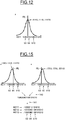
- the random distribution DB1 of threshold voltage VT is illustrated very schematically on the figure 3 and can be translated in particular, as illustrated on the figure 4 by a random distribution DB2 of the Ion / Ioff ratio between the current Ion of the transistor in the on state and the current Ioff of the transistor in the off state.
- the values of the Ion currents of the different transistors TR1i and TR2j vary around an average value of 631 microamperes per micrometer with a deviation of 41%.
- each first transistor TR1i (i varying from 1 to N) is an NMOS transistor arranged in a diode arrangement, that is to say having its gate connected to the drain, for example by metallization.
- All the first transistors TR1i are connected in parallel between a common terminal BGC and a reference power supply terminal B2 intended to receive a reference supply voltage, for example the ground GND.
- the first coupling means here comprise links, for example by metallizations, connecting the common terminal BGC to the gates of the K second transistors TR2j.
- Each second transistor TR2j is furthermore coupled between terminal B2 and the corresponding common node NCj.
- the first coupling means also comprise here a current mirror MR connected between the common terminal BGC and each of the common nodes NCj.
- the current mirror MR here comprises a PMOS main transistor referenced TRP whose source is connected to a power supply terminal B1 intended to receive a supply voltage Vdd.
- This main transistor TRP is diode-mounted with its gate connected to its drain.
- the drain of the transistor TRP is connected to the common terminal BGC.
- the current mirror MR also comprises K secondary transistors TRS1-TRSK each connected between the supply terminal B1 and the corresponding common node NCj.
- the gates of the secondary transistors TRSj are connected to the gate and the drain of the main transistor TRP.
- the ratio between the size of the main transistor TRP and the size of each secondary transistor TRSj is equal to N, that is to say the number of first transistors TR1i.
- this size ratio can be obtained by a size of the transistor TRP actually N times larger than the size of a secondary transistor TRSj or else for example N main transistors of size 1 and connected in parallel.
- the device DIS furthermore comprises second coupling means between each common node NCj and a corresponding output node NSj of said device DIS.
- These second coupling means include in this example between each common node NCj and each output node NSj a comparator CMPj whose first input is connected to the common node NCj, a second input is intended to receive a reference voltage equal to half of the supply voltage Vdd and the output of which is connected to the output node NSj.
- each output node will deliver an output signal whose level will depend on the comparison between the level of a reference current delivered by the corresponding secondary transistor TRSj and the current level. passing through the second corresponding transistor TR2j.
- the main transistor TRP when the DD domain of the integrated circuit comprising the device DIS is powered by the supply voltage Vdd, the main transistor TRP generates a main current IP which is distributed in the first N transistors TR11-TR1N.
- Each first transistor TR1i is traversed by a current I1i.
- This distribution of the main current in the first N transistors TR1i generates for each first transistor, and therefore at the common terminal BGC, a first average source gate voltage VGSM.
- This average source gate voltage VGSM polarizes the gate of each second transistor TR2j. Of course, this voltage VGSM is greater than the threshold voltage of the transistors.
- Each second transistor TR2j is crossed by a current ITRj.
- each secondary transistor TRSj delivers to the corresponding common node NCj a reference current IRj.
- This reference current IRj also hereinafter referred to as base current, is identical for each transistor TRSj and corresponds to 1 / Nth of the main current IP.
- the current IP corresponds to the sum of the N currents I1i crossing the first N transistors TR1i.
- 1 / nth of this IP current represents the average of the currents flowing through the first N TR1i transistors.
- the current flowing through a second transistor TR2k or TR2j can be located, as illustrated in FIG. figure 6 on one side or the other of the reference current IRj.
- the transistor TR2k draws the current ITRk whose level is below the level of the reference current IRj, the corresponding common node NCk rises to a voltage greater than Vdd / 2.
- the comparator CMPj checks whether the current ITRj crossing the second corresponding transistor TR2j is less than or not the reference current IRj which is the same for all the secondary transistors TRS1-TRSK.
- the output signal SSj delivered to the output node NSj has a voltage of V1 volt while in the opposite case it has a voltage of zero.
- the value of the corresponding bit bj of the code delivered by the physically nonclonable function is equal to 1 while it is equal to 0 in the second case.
- the embodiment of the DIS device illustrated on the figure 8 differs from the one shown on the figure 2 in that the current mirror of the device of the figure 2 is replaced by a current divider block BLCD.
- This current divider block comprises the main transistor TRP and auxiliary transistors TRS1-TRSK in a size ratio of N to 1.
- the gates of the PMOS transistors TRP and TRS1-TRSK are all connected and intended to to be biased by a bias voltage Vbias which can typically be equal to Vdd minus a fixed voltage value, for example 1 volt.
- This operation is essentially similar to that described with reference to the figure 5 .
- the main transistor TRP imposes the main current IP which is distributed in the first N transistors TR11- TR1N.
- the first average source gate voltage VGSM polarizes the gates of the second transistors TR21-TR2K.
- this embodiment makes it possible, by means of the bias voltage Vbias, to adjust the value of the current IP and thus to reduce the consumption of the device.
- the value of the current IP also makes it possible to adjust the value of the first average source gate voltage VGSM which, when approaching the threshold voltage of the transistors TR21-TR2K, allows to widen the distribution of values of the individual currents ITRj crossing the second transistors TR2j.
- first coupling means further comprise an auxiliary current source SCA controllable by a control signal SC delivered by MCM control means and capable of delivering on the common terminal BGC an auxiliary current or the opposite auxiliary current.
- the first coupling means are then in a first state which corresponds to that illustrated on FIG. figure 8 .
- the first coupling means are then in a second state as illustrated on FIG. figure 11 .
- This embodiment of figures 10 and 11 detects bits of the digital code delivered by the DIS device whose values may not be stable and repeatable.
- the characteristics of the comparator CMPj can lead to comparisons giving unstable or non-repeatable values from one energization to another.
- the auxiliary power source SCA will be controlled to deliver an auxiliary current IX which will be superimposed on the main current IP, this superimposed current being distributed in the first N transistors TR11-TR1N.
- the value of the reference current IRj always remains equal to the value of the base current corresponding to 1 N / th of the main current IP.
- bits b3, b6 and b10 are therefore 0.
- the auxiliary power source SCA is then controlled to deliver the opposite of the IX auxiliary current IX.
- the superimposed current which will be distributed in the first N transistors TR11-TR1N is equal to IP-IX generating a mean source gate voltage VGSM3 at the common terminal BGC.
- the level of the reference current IRj remains equal to the base current corresponding to 1 / Nth of the main current IP.
- MTR processing means ( figures 10 , 11 , 13 and 14 ) will then compare the digital code KEY delivered to the output nodes NSj of the DIS device, bit by bit, so as to locate the bits whose logical values have changed between a shift to the right and a shift to the left of the distribution.
- processing means perform, as illustrated on the figure 15 , this comparison in step 140 and deliver comparison signals SDj ( figures 10 , 11 , 13 and 14 ) representative of the results of this comparison.
- the processing means may comprise logic circuits.
- bits b3, b6 and b10 have in this example been marked and are marked with crosses.
- the processing means make a decision as to the management of these unstable bits (step 141 figure 15 ).
- a first solution consists in not taking into account these unstable bits in the digital code delivered by the device DIS.
- the numerical code KEY1 will not include bits b3, b6 and b10.
- Another solution consists in conferring an arbitrary logical value on these bits b3, b6 and b10.
- the DIS device can then be put back into its first state corresponding to that illustrated in FIG. figure 10 and the decision taken on the unstable bit remains memorized and valid for the rest.
- the voltage source SCA is connected to the common terminal BGC, which is particularly simple to achieve, it would however be possible alternatively to connect an auxiliary voltage source SCA at the drain of each secondary PMOS transistor TRSj ( figure 16 ).
- the digital code generated by the device DIS is independent of the temperature and aging conditions since all the transistors of this device DIS are subjected to the same temperature variations and the same aging and that in any case, the polarization of the gates of the secondary transistors and the generation of the reference current results from an average of the currents flowing through the different transistors having a randomly modified threshold voltage.
- Figures 17 to 19 illustrate a nonlimiting example of a method for producing a DIS device for obtaining in a simple manner a random distribution of threshold voltages.
- the production method comprises after formation on the substrate of the entire semiconductor WF plate of a dielectric layer 2, for example silicon dioxide, the formation of a layer of polysilicon (polycrystalline silicon) 3.
- a dielectric layer 2 for example silicon dioxide
- the method also comprises forming on this polysilicon layer 3 a mask 4, for example a resin mask, having openings 40.
- these openings 40 are located next to the future first transistors TR1i and future second transistors TR2i.
- An initial implantation IMP, in the WF wafer substrate, of dopants having the same type of conductivity as the source and drain regions of all the future first transistors and second MOS transistors is then carried out.
- first transistors and the second transistors are NMOS transistors
- an arsenic or phosphorus implantation whereas if the first and second MOS transistors are PMOS transistors, an implantation can be carried out. of boron.
- the regions of the substrate 1 of the semiconductor wafer located under a region of the polysilicon layer 3 protected by the resin do not directly undergo the implantation of IMP dopants.
- the implantation of IMP dopants results in a lateral implantation typically tilted at an angle of less than 45 °, in the regions of the substrate next to the openings 40.
- each first or second transistor TR1i has in the substrate an active area incorporating part of an initial implanted region.
- the channel region ZC of the MOS transistor TR1i has received a portion of the initial arsenic implants and its length has therefore been modified in relation to to a standard transistor, which led to a change in its threshold voltage.
- the initial implantation of dopants through the polysilicon layer modified from randomly the threshold voltages of all the first and second transistors.
- transistor TRSS is a conventional transistor or a "dummy" transistor always passing.
- the size of the aperture of the vignettes is compatible with the height of the polysilicon layer so as to obtain this tilted implantation.
- first transistors TR1i and the second transistors TR2j may be PMOS transistors.
- the transistors TRP and TRSj of the current mirror MP or the current divider block BLCD may be conventional transistors or else at randomly modified threshold voltage.
- the transistors TR1i and TR2j may advantageously be grouped together within the integrated circuit.
Landscapes
- Engineering & Computer Science (AREA)
- Physics & Mathematics (AREA)
- Power Engineering (AREA)
- General Physics & Mathematics (AREA)
- Condensed Matter Physics & Semiconductors (AREA)
- Computer Hardware Design (AREA)
- Microelectronics & Electronic Packaging (AREA)
- Computer Security & Cryptography (AREA)
- Manufacturing & Machinery (AREA)
- High Energy & Nuclear Physics (AREA)
- Signal Processing (AREA)
- Computer Networks & Wireless Communication (AREA)
- Software Systems (AREA)
- Toxicology (AREA)
- Health & Medical Sciences (AREA)
- Theoretical Computer Science (AREA)
- Geometry (AREA)
- General Engineering & Computer Science (AREA)
- Semiconductor Integrated Circuits (AREA)
- Logic Circuits (AREA)
Applications Claiming Priority (1)
| Application Number | Priority Date | Filing Date | Title |
|---|---|---|---|
| FR1752336A FR3064435A1 (fr) | 2017-03-22 | 2017-03-22 | Dispositif integre de fonction physiquement non clonable, et procede de realisation |
Publications (2)
| Publication Number | Publication Date |
|---|---|
| EP3379770A1 true EP3379770A1 (de) | 2018-09-26 |
| EP3379770B1 EP3379770B1 (de) | 2019-05-22 |
Family
ID=59649788
Family Applications (1)
| Application Number | Title | Priority Date | Filing Date |
|---|---|---|---|
| EP17186783.1A Active EP3379770B1 (de) | 2017-03-22 | 2017-08-18 | Integriertes gerät mit physisch unklonbarer funktion, und herstellungsverfahren |
Country Status (4)
| Country | Link |
|---|---|
| US (1) | US10833027B2 (de) |
| EP (1) | EP3379770B1 (de) |
| CN (2) | CN108630682B (de) |
| FR (1) | FR3064435A1 (de) |
Cited By (1)
| Publication number | Priority date | Publication date | Assignee | Title |
|---|---|---|---|---|
| WO2020120847A1 (fr) * | 2018-12-13 | 2020-06-18 | Stmicroelectronics (Rousset) Sas | Dispositif de fonction physiquement non clonable |
Families Citing this family (5)
| Publication number | Priority date | Publication date | Assignee | Title |
|---|---|---|---|---|
| FR3064435A1 (fr) * | 2017-03-22 | 2018-09-28 | Stmicroelectronics (Crolles 2) Sas | Dispositif integre de fonction physiquement non clonable, et procede de realisation |
| CN109427667B (zh) * | 2017-09-01 | 2021-11-30 | 中芯国际集成电路制造(上海)有限公司 | 具有物理不可克隆功能的器件及其制造方法、芯片 |
| FR3093232A1 (fr) * | 2019-02-22 | 2020-08-28 | Stmicroelectronics (Crolles 2) Sas | Dispositif de fonction physiquement non-clonable à transistors, et procédé de réalisation |
| FR3093231A1 (fr) * | 2019-02-22 | 2020-08-28 | Stmicroelectronics (Rousset) Sas | Dispositif de fonction physiquement non clonable à transistors à grille flottante, et procédé de réalisation |
| US11411749B2 (en) * | 2020-01-31 | 2022-08-09 | Nxp B.V. | System and method for performing netlist obfuscation for a semiconductor device |
Citations (2)
| Publication number | Priority date | Publication date | Assignee | Title |
|---|---|---|---|---|
| US20110317829A1 (en) * | 2010-06-25 | 2011-12-29 | International Business Machines Corporation | Physically Unclonable Function Implemented Through Threshold Voltage Comparison |
| US20130322617A1 (en) * | 2012-06-05 | 2013-12-05 | Board Of Regents, The University Of Texas System | Physically unclonable functions based on non-linearity of sub-threshold operation |
Family Cites Families (2)
| Publication number | Priority date | Publication date | Assignee | Title |
|---|---|---|---|---|
| CN105245220A (zh) * | 2015-09-25 | 2016-01-13 | 深圳大学 | 一种物理不可克隆芯片电路 |
| FR3064435A1 (fr) * | 2017-03-22 | 2018-09-28 | Stmicroelectronics (Crolles 2) Sas | Dispositif integre de fonction physiquement non clonable, et procede de realisation |
-
2017
- 2017-03-22 FR FR1752336A patent/FR3064435A1/fr active Pending
- 2017-08-18 EP EP17186783.1A patent/EP3379770B1/de active Active
- 2017-09-14 CN CN201710828035.8A patent/CN108630682B/zh active Active
- 2017-09-14 CN CN201721178739.7U patent/CN207382331U/zh not_active Withdrawn - After Issue
- 2017-10-16 US US15/784,883 patent/US10833027B2/en active Active
Patent Citations (2)
| Publication number | Priority date | Publication date | Assignee | Title |
|---|---|---|---|---|
| US20110317829A1 (en) * | 2010-06-25 | 2011-12-29 | International Business Machines Corporation | Physically Unclonable Function Implemented Through Threshold Voltage Comparison |
| US20130322617A1 (en) * | 2012-06-05 | 2013-12-05 | Board Of Regents, The University Of Texas System | Physically unclonable functions based on non-linearity of sub-threshold operation |
Non-Patent Citations (1)
| Title |
|---|
| WENJIE CHE ET AL: "A non-volatile memory based physically unclonable function without helper data", COMPUTER-AIDED DESIGN, IEEE PRESS, 445 HOES LANE, PO BOX 1331, PISCATAWAY, NJ 08855-1331 USA, 3 November 2014 (2014-11-03), pages 148 - 153, XP058062251, ISBN: 978-1-4799-6277-8, DOI: 10.1109/ICCAD.2014.7001345 * |
Cited By (3)
| Publication number | Priority date | Publication date | Assignee | Title |
|---|---|---|---|---|
| WO2020120847A1 (fr) * | 2018-12-13 | 2020-06-18 | Stmicroelectronics (Rousset) Sas | Dispositif de fonction physiquement non clonable |
| US11374569B2 (en) | 2018-12-13 | 2022-06-28 | Stmicroelectronics (Rousset) Sas | Physically unclonable function device |
| US11804842B2 (en) | 2018-12-13 | 2023-10-31 | Stmicroelectronics (Rousset) Sas | Physically unclonable function device |
Also Published As
| Publication number | Publication date |
|---|---|
| US10833027B2 (en) | 2020-11-10 |
| CN108630682B (zh) | 2023-06-20 |
| FR3064435A1 (fr) | 2018-09-28 |
| CN108630682A (zh) | 2018-10-09 |
| US20180277496A1 (en) | 2018-09-27 |
| EP3379770B1 (de) | 2019-05-22 |
| CN207382331U (zh) | 2018-05-18 |
Similar Documents
| Publication | Publication Date | Title |
|---|---|---|
| EP3379770B1 (de) | Integriertes gerät mit physisch unklonbarer funktion, und herstellungsverfahren | |
| EP2171851B1 (de) | Rekonfigurierbare logikzelle aus doppelgate-mosfet-transistoren | |
| EP3895371A1 (de) | Physikalisch unklonbare funktionsvorrichtung | |
| EP3176669B1 (de) | Schaltkreis zur erzeugung einer referenzspannung | |
| EP2577730B1 (de) | Integrierte schaltung mit einem übergangslosen fet mit verarmungsschicht | |
| EP0594834B1 (de) | In Standard-CMOS-Technologie realisierte, zwischen einer Logikschaltung mit niedriger Versorgungsspannung und einer Ausgangsstufe mit hoher Versorgungsspannung, liegende Schaltung | |
| EP3246943B1 (de) | Elektronische vorrichtung mit puf-basierter identifizierung | |
| EP3605543B1 (de) | Detektionsverfahren eines angriffs durch einen elektrisch geladenen teilchenstrahl auf einen integrierten schaltkreis, und entsprechender integrierter schaltkreis | |
| EP0718887A1 (de) | Abgleichschaltung für Widerstände | |
| US20150207505A1 (en) | Semiconductor device including enhanced variability | |
| FR2957193A1 (fr) | Cellule a chemin de donnees sur substrat seoi avec grille de controle arriere enterree sous la couche isolante | |
| EP1755222A1 (de) | Logikzelle mit zwei isolierten redundanten Ausgängen, und integrierte Schaltung dafür | |
| EP3473592A1 (de) | Quantenvorrichtung mit modulierbar gekoppelten spin-qubits | |
| EP1073202B1 (de) | Steuerschaltung für einen Pegelumsetzer-Hochspannungsschalter | |
| FR2735904A1 (fr) | Procede de realisation d'un semi-conducteur avec une zone fortement dopee situee entre des zones faiblement dopees, pour la fabrication de transistors | |
| FR2957457A1 (fr) | Procede de fabrication d'un point memoire anti-fusible | |
| EP0915480B1 (de) | Nichtflüchtiger MOS-Speicher | |
| FR2795557A1 (fr) | Dispositif d'ajustement des circuits apres mise en boitier et procede de fabrication correspondant | |
| FR3058857A1 (fr) | Capteur d'images cmos a bruit reduit | |
| FR3049765A1 (de) | ||
| EP2109112A1 (de) | Programmierverfahren einer Speichervorrichtung vom einmal programmierbaren Typ und integrierter Schaltkreis, der eine solche Speichervorrichtung umfasst | |
| EP3886361A1 (de) | Physisch nicht klonbares funktionsgerät | |
| FR2967522A1 (fr) | Memoire non-volatile securisee | |
| FR2964247A1 (fr) | Dispositif electronique comportant un etage tampon et des moyens de protection contre les decharges electrostatiques | |
| WO2005099264A1 (fr) | Méthode de sécurisation d'un contenu chiffré transmis par un diffuseur |
Legal Events
| Date | Code | Title | Description |
|---|---|---|---|
| PUAI | Public reference made under article 153(3) epc to a published international application that has entered the european phase |
Free format text: ORIGINAL CODE: 0009012 |
|
| STAA | Information on the status of an ep patent application or granted ep patent |
Free format text: STATUS: REQUEST FOR EXAMINATION WAS MADE |
|
| 17P | Request for examination filed |
Effective date: 20170818 |
|
| AK | Designated contracting states |
Kind code of ref document: A1 Designated state(s): AL AT BE BG CH CY CZ DE DK EE ES FI FR GB GR HR HU IE IS IT LI LT LU LV MC MK MT NL NO PL PT RO RS SE SI SK SM TR |
|
| AX | Request for extension of the european patent |
Extension state: BA ME |
|
| GRAP | Despatch of communication of intention to grant a patent |
Free format text: ORIGINAL CODE: EPIDOSNIGR1 |
|
| STAA | Information on the status of an ep patent application or granted ep patent |
Free format text: STATUS: GRANT OF PATENT IS INTENDED |
|
| INTG | Intention to grant announced |
Effective date: 20190212 |
|
| GRAJ | Information related to disapproval of communication of intention to grant by the applicant or resumption of examination proceedings by the epo deleted |
Free format text: ORIGINAL CODE: EPIDOSDIGR1 |
|
| STAA | Information on the status of an ep patent application or granted ep patent |
Free format text: STATUS: REQUEST FOR EXAMINATION WAS MADE |
|
| GRAR | Information related to intention to grant a patent recorded |
Free format text: ORIGINAL CODE: EPIDOSNIGR71 |
|
| GRAS | Grant fee paid |
Free format text: ORIGINAL CODE: EPIDOSNIGR3 |
|
| STAA | Information on the status of an ep patent application or granted ep patent |
Free format text: STATUS: GRANT OF PATENT IS INTENDED |
|
| GRAA | (expected) grant |
Free format text: ORIGINAL CODE: 0009210 |
|
| STAA | Information on the status of an ep patent application or granted ep patent |
Free format text: STATUS: THE PATENT HAS BEEN GRANTED |
|
| INTC | Intention to grant announced (deleted) | ||
| INTG | Intention to grant announced |
Effective date: 20190408 |
|
| AK | Designated contracting states |
Kind code of ref document: B1 Designated state(s): AL AT BE BG CH CY CZ DE DK EE ES FI FR GB GR HR HU IE IS IT LI LT LU LV MC MK MT NL NO PL PT RO RS SE SI SK SM TR |
|
| REG | Reference to a national code |
Ref country code: GB Ref legal event code: FG4D Free format text: NOT ENGLISH |
|
| REG | Reference to a national code |
Ref country code: CH Ref legal event code: EP |
|
| REG | Reference to a national code |
Ref country code: IE Ref legal event code: FG4D Free format text: LANGUAGE OF EP DOCUMENT: FRENCH |
|
| REG | Reference to a national code |
Ref country code: DE Ref legal event code: R096 Ref document number: 602017004094 Country of ref document: DE |
|
| REG | Reference to a national code |
Ref country code: AT Ref legal event code: REF Ref document number: 1137403 Country of ref document: AT Kind code of ref document: T Effective date: 20190615 |
|
| REG | Reference to a national code |
Ref country code: NL Ref legal event code: MP Effective date: 20190522 |
|
| REG | Reference to a national code |
Ref country code: LT Ref legal event code: MG4D |
|
| PG25 | Lapsed in a contracting state [announced via postgrant information from national office to epo] |
Ref country code: HR Free format text: LAPSE BECAUSE OF FAILURE TO SUBMIT A TRANSLATION OF THE DESCRIPTION OR TO PAY THE FEE WITHIN THE PRESCRIBED TIME-LIMIT Effective date: 20190522 Ref country code: SE Free format text: LAPSE BECAUSE OF FAILURE TO SUBMIT A TRANSLATION OF THE DESCRIPTION OR TO PAY THE FEE WITHIN THE PRESCRIBED TIME-LIMIT Effective date: 20190522 Ref country code: NL Free format text: LAPSE BECAUSE OF FAILURE TO SUBMIT A TRANSLATION OF THE DESCRIPTION OR TO PAY THE FEE WITHIN THE PRESCRIBED TIME-LIMIT Effective date: 20190522 Ref country code: LT Free format text: LAPSE BECAUSE OF FAILURE TO SUBMIT A TRANSLATION OF THE DESCRIPTION OR TO PAY THE FEE WITHIN THE PRESCRIBED TIME-LIMIT Effective date: 20190522 Ref country code: ES Free format text: LAPSE BECAUSE OF FAILURE TO SUBMIT A TRANSLATION OF THE DESCRIPTION OR TO PAY THE FEE WITHIN THE PRESCRIBED TIME-LIMIT Effective date: 20190522 Ref country code: NO Free format text: LAPSE BECAUSE OF FAILURE TO SUBMIT A TRANSLATION OF THE DESCRIPTION OR TO PAY THE FEE WITHIN THE PRESCRIBED TIME-LIMIT Effective date: 20190822 Ref country code: AL Free format text: LAPSE BECAUSE OF FAILURE TO SUBMIT A TRANSLATION OF THE DESCRIPTION OR TO PAY THE FEE WITHIN THE PRESCRIBED TIME-LIMIT Effective date: 20190522 Ref country code: PT Free format text: LAPSE BECAUSE OF FAILURE TO SUBMIT A TRANSLATION OF THE DESCRIPTION OR TO PAY THE FEE WITHIN THE PRESCRIBED TIME-LIMIT Effective date: 20190922 Ref country code: FI Free format text: LAPSE BECAUSE OF FAILURE TO SUBMIT A TRANSLATION OF THE DESCRIPTION OR TO PAY THE FEE WITHIN THE PRESCRIBED TIME-LIMIT Effective date: 20190522 |
|
| PG25 | Lapsed in a contracting state [announced via postgrant information from national office to epo] |
Ref country code: BG Free format text: LAPSE BECAUSE OF FAILURE TO SUBMIT A TRANSLATION OF THE DESCRIPTION OR TO PAY THE FEE WITHIN THE PRESCRIBED TIME-LIMIT Effective date: 20190822 Ref country code: GR Free format text: LAPSE BECAUSE OF FAILURE TO SUBMIT A TRANSLATION OF THE DESCRIPTION OR TO PAY THE FEE WITHIN THE PRESCRIBED TIME-LIMIT Effective date: 20190823 Ref country code: RS Free format text: LAPSE BECAUSE OF FAILURE TO SUBMIT A TRANSLATION OF THE DESCRIPTION OR TO PAY THE FEE WITHIN THE PRESCRIBED TIME-LIMIT Effective date: 20190522 Ref country code: LV Free format text: LAPSE BECAUSE OF FAILURE TO SUBMIT A TRANSLATION OF THE DESCRIPTION OR TO PAY THE FEE WITHIN THE PRESCRIBED TIME-LIMIT Effective date: 20190522 |
|
| REG | Reference to a national code |
Ref country code: AT Ref legal event code: MK05 Ref document number: 1137403 Country of ref document: AT Kind code of ref document: T Effective date: 20190522 |
|
| PG25 | Lapsed in a contracting state [announced via postgrant information from national office to epo] |
Ref country code: EE Free format text: LAPSE BECAUSE OF FAILURE TO SUBMIT A TRANSLATION OF THE DESCRIPTION OR TO PAY THE FEE WITHIN THE PRESCRIBED TIME-LIMIT Effective date: 20190522 Ref country code: DK Free format text: LAPSE BECAUSE OF FAILURE TO SUBMIT A TRANSLATION OF THE DESCRIPTION OR TO PAY THE FEE WITHIN THE PRESCRIBED TIME-LIMIT Effective date: 20190522 Ref country code: AT Free format text: LAPSE BECAUSE OF FAILURE TO SUBMIT A TRANSLATION OF THE DESCRIPTION OR TO PAY THE FEE WITHIN THE PRESCRIBED TIME-LIMIT Effective date: 20190522 Ref country code: SK Free format text: LAPSE BECAUSE OF FAILURE TO SUBMIT A TRANSLATION OF THE DESCRIPTION OR TO PAY THE FEE WITHIN THE PRESCRIBED TIME-LIMIT Effective date: 20190522 Ref country code: CZ Free format text: LAPSE BECAUSE OF FAILURE TO SUBMIT A TRANSLATION OF THE DESCRIPTION OR TO PAY THE FEE WITHIN THE PRESCRIBED TIME-LIMIT Effective date: 20190522 Ref country code: RO Free format text: LAPSE BECAUSE OF FAILURE TO SUBMIT A TRANSLATION OF THE DESCRIPTION OR TO PAY THE FEE WITHIN THE PRESCRIBED TIME-LIMIT Effective date: 20190522 |
|
| REG | Reference to a national code |
Ref country code: DE Ref legal event code: R097 Ref document number: 602017004094 Country of ref document: DE |
|
| PG25 | Lapsed in a contracting state [announced via postgrant information from national office to epo] |
Ref country code: IT Free format text: LAPSE BECAUSE OF FAILURE TO SUBMIT A TRANSLATION OF THE DESCRIPTION OR TO PAY THE FEE WITHIN THE PRESCRIBED TIME-LIMIT Effective date: 20190522 Ref country code: SM Free format text: LAPSE BECAUSE OF FAILURE TO SUBMIT A TRANSLATION OF THE DESCRIPTION OR TO PAY THE FEE WITHIN THE PRESCRIBED TIME-LIMIT Effective date: 20190522 |
|
| PLBE | No opposition filed within time limit |
Free format text: ORIGINAL CODE: 0009261 |
|
| STAA | Information on the status of an ep patent application or granted ep patent |
Free format text: STATUS: NO OPPOSITION FILED WITHIN TIME LIMIT |
|
| PG25 | Lapsed in a contracting state [announced via postgrant information from national office to epo] |
Ref country code: TR Free format text: LAPSE BECAUSE OF FAILURE TO SUBMIT A TRANSLATION OF THE DESCRIPTION OR TO PAY THE FEE WITHIN THE PRESCRIBED TIME-LIMIT Effective date: 20190522 |
|
| 26N | No opposition filed |
Effective date: 20200225 |
|
| PG25 | Lapsed in a contracting state [announced via postgrant information from national office to epo] |
Ref country code: PL Free format text: LAPSE BECAUSE OF FAILURE TO SUBMIT A TRANSLATION OF THE DESCRIPTION OR TO PAY THE FEE WITHIN THE PRESCRIBED TIME-LIMIT Effective date: 20190522 |
|
| PG25 | Lapsed in a contracting state [announced via postgrant information from national office to epo] |
Ref country code: LU Free format text: LAPSE BECAUSE OF NON-PAYMENT OF DUE FEES Effective date: 20190818 Ref country code: MC Free format text: LAPSE BECAUSE OF FAILURE TO SUBMIT A TRANSLATION OF THE DESCRIPTION OR TO PAY THE FEE WITHIN THE PRESCRIBED TIME-LIMIT Effective date: 20190522 |
|
| REG | Reference to a national code |
Ref country code: BE Ref legal event code: MM Effective date: 20190831 |
|
| PG25 | Lapsed in a contracting state [announced via postgrant information from national office to epo] |
Ref country code: FR Free format text: LAPSE BECAUSE OF NON-PAYMENT OF DUE FEES Effective date: 20190831 Ref country code: IE Free format text: LAPSE BECAUSE OF NON-PAYMENT OF DUE FEES Effective date: 20190818 |
|
| PG25 | Lapsed in a contracting state [announced via postgrant information from national office to epo] |
Ref country code: BE Free format text: LAPSE BECAUSE OF NON-PAYMENT OF DUE FEES Effective date: 20190831 |
|
| REG | Reference to a national code |
Ref country code: CH Ref legal event code: PL |
|
| PG25 | Lapsed in a contracting state [announced via postgrant information from national office to epo] |
Ref country code: LI Free format text: LAPSE BECAUSE OF NON-PAYMENT OF DUE FEES Effective date: 20200831 Ref country code: CH Free format text: LAPSE BECAUSE OF NON-PAYMENT OF DUE FEES Effective date: 20200831 |
|
| PG25 | Lapsed in a contracting state [announced via postgrant information from national office to epo] |
Ref country code: CY Free format text: LAPSE BECAUSE OF FAILURE TO SUBMIT A TRANSLATION OF THE DESCRIPTION OR TO PAY THE FEE WITHIN THE PRESCRIBED TIME-LIMIT Effective date: 20190522 |
|
| PG25 | Lapsed in a contracting state [announced via postgrant information from national office to epo] |
Ref country code: IS Free format text: LAPSE BECAUSE OF FAILURE TO SUBMIT A TRANSLATION OF THE DESCRIPTION OR TO PAY THE FEE WITHIN THE PRESCRIBED TIME-LIMIT Effective date: 20190922 |
|
| PG25 | Lapsed in a contracting state [announced via postgrant information from national office to epo] |
Ref country code: HU Free format text: LAPSE BECAUSE OF FAILURE TO SUBMIT A TRANSLATION OF THE DESCRIPTION OR TO PAY THE FEE WITHIN THE PRESCRIBED TIME-LIMIT; INVALID AB INITIO Effective date: 20170818 Ref country code: MT Free format text: LAPSE BECAUSE OF FAILURE TO SUBMIT A TRANSLATION OF THE DESCRIPTION OR TO PAY THE FEE WITHIN THE PRESCRIBED TIME-LIMIT Effective date: 20190522 |
|
| PG25 | Lapsed in a contracting state [announced via postgrant information from national office to epo] |
Ref country code: SI Free format text: LAPSE BECAUSE OF FAILURE TO SUBMIT A TRANSLATION OF THE DESCRIPTION OR TO PAY THE FEE WITHIN THE PRESCRIBED TIME-LIMIT Effective date: 20190522 |
|
| GBPC | Gb: european patent ceased through non-payment of renewal fee |
Effective date: 20210818 |
|
| PG25 | Lapsed in a contracting state [announced via postgrant information from national office to epo] |
Ref country code: MK Free format text: LAPSE BECAUSE OF FAILURE TO SUBMIT A TRANSLATION OF THE DESCRIPTION OR TO PAY THE FEE WITHIN THE PRESCRIBED TIME-LIMIT Effective date: 20190522 |
|
| PG25 | Lapsed in a contracting state [announced via postgrant information from national office to epo] |
Ref country code: GB Free format text: LAPSE BECAUSE OF NON-PAYMENT OF DUE FEES Effective date: 20210818 |
|
| PGFP | Annual fee paid to national office [announced via postgrant information from national office to epo] |
Ref country code: DE Payment date: 20230720 Year of fee payment: 7 |