EP3379717B1 - Drehzahlvariables pumpspeicherkraftwerk und drehzahlvariables pumpspeicherkraftverfahren - Google Patents
Drehzahlvariables pumpspeicherkraftwerk und drehzahlvariables pumpspeicherkraftverfahren Download PDFInfo
- Publication number
- EP3379717B1 EP3379717B1 EP18159620.6A EP18159620A EP3379717B1 EP 3379717 B1 EP3379717 B1 EP 3379717B1 EP 18159620 A EP18159620 A EP 18159620A EP 3379717 B1 EP3379717 B1 EP 3379717B1
- Authority
- EP
- European Patent Office
- Prior art keywords
- circuit
- short
- variable
- phase
- voltage
- Prior art date
- Legal status (The legal status is an assumption and is not a legal conclusion. Google has not performed a legal analysis and makes no representation as to the accuracy of the status listed.)
- Active
Links
Images


Classifications
-
- H—ELECTRICITY
- H02—GENERATION; CONVERSION OR DISTRIBUTION OF ELECTRIC POWER
- H02P—CONTROL OR REGULATION OF ELECTRIC MOTORS, ELECTRIC GENERATORS OR DYNAMO-ELECTRIC CONVERTERS; CONTROLLING TRANSFORMERS, REACTORS OR CHOKE COILS
- H02P9/00—Arrangements for controlling electric generators for the purpose of obtaining a desired output
- H02P9/10—Control effected upon generator excitation circuit to reduce harmful effects of overloads or transients, e.g. sudden application of load, sudden removal of load, sudden change of load
- H02P9/107—Control effected upon generator excitation circuit to reduce harmful effects of overloads or transients, e.g. sudden application of load, sudden removal of load, sudden change of load for limiting effects of overloads
-
- H—ELECTRICITY
- H02—GENERATION; CONVERSION OR DISTRIBUTION OF ELECTRIC POWER
- H02H—EMERGENCY PROTECTIVE CIRCUIT ARRANGEMENTS
- H02H3/00—Emergency protective circuit arrangements for automatic disconnection directly responsive to an undesired change from normal electric working condition with or without subsequent reconnection ; integrated protection
- H02H3/20—Emergency protective circuit arrangements for automatic disconnection directly responsive to an undesired change from normal electric working condition with or without subsequent reconnection ; integrated protection responsive to excess voltage
-
- H—ELECTRICITY
- H02—GENERATION; CONVERSION OR DISTRIBUTION OF ELECTRIC POWER
- H02H—EMERGENCY PROTECTIVE CIRCUIT ARRANGEMENTS
- H02H7/00—Emergency protective circuit arrangements specially adapted for specific types of electric machines or apparatus or for sectionalised protection of cable or line systems, and effecting automatic switching in the event of an undesired change from normal working conditions
- H02H7/08—Emergency protective circuit arrangements specially adapted for specific types of electric machines or apparatus or for sectionalised protection of cable or line systems, and effecting automatic switching in the event of an undesired change from normal working conditions for dynamo-electric motors
- H02H7/09—Emergency protective circuit arrangements specially adapted for specific types of electric machines or apparatus or for sectionalised protection of cable or line systems, and effecting automatic switching in the event of an undesired change from normal working conditions for dynamo-electric motors against over-voltage; against reduction of voltage; against phase interruption
-
- H—ELECTRICITY
- H02—GENERATION; CONVERSION OR DISTRIBUTION OF ELECTRIC POWER
- H02H—EMERGENCY PROTECTIVE CIRCUIT ARRANGEMENTS
- H02H7/00—Emergency protective circuit arrangements specially adapted for specific types of electric machines or apparatus or for sectionalised protection of cable or line systems, and effecting automatic switching in the event of an undesired change from normal working conditions
- H02H7/10—Emergency protective circuit arrangements specially adapted for specific types of electric machines or apparatus or for sectionalised protection of cable or line systems, and effecting automatic switching in the event of an undesired change from normal working conditions for converters; for rectifiers
- H02H7/12—Emergency protective circuit arrangements specially adapted for specific types of electric machines or apparatus or for sectionalised protection of cable or line systems, and effecting automatic switching in the event of an undesired change from normal working conditions for converters; for rectifiers for static converters or rectifiers
-
- H—ELECTRICITY
- H02—GENERATION; CONVERSION OR DISTRIBUTION OF ELECTRIC POWER
- H02H—EMERGENCY PROTECTIVE CIRCUIT ARRANGEMENTS
- H02H9/00—Emergency protective circuit arrangements for limiting excess current or voltage without disconnection
- H02H9/04—Emergency protective circuit arrangements for limiting excess current or voltage without disconnection responsive to excess voltage
- H02H9/041—Emergency protective circuit arrangements for limiting excess current or voltage without disconnection responsive to excess voltage using a short-circuiting device
-
- H—ELECTRICITY
- H02—GENERATION; CONVERSION OR DISTRIBUTION OF ELECTRIC POWER
- H02H—EMERGENCY PROTECTIVE CIRCUIT ARRANGEMENTS
- H02H9/00—Emergency protective circuit arrangements for limiting excess current or voltage without disconnection
- H02H9/04—Emergency protective circuit arrangements for limiting excess current or voltage without disconnection responsive to excess voltage
- H02H9/042—Emergency protective circuit arrangements for limiting excess current or voltage without disconnection responsive to excess voltage comprising means to limit the absorbed power or indicate damaged over-voltage protection device
-
- H—ELECTRICITY
- H02—GENERATION; CONVERSION OR DISTRIBUTION OF ELECTRIC POWER
- H02P—CONTROL OR REGULATION OF ELECTRIC MOTORS, ELECTRIC GENERATORS OR DYNAMO-ELECTRIC CONVERTERS; CONTROLLING TRANSFORMERS, REACTORS OR CHOKE COILS
- H02P29/00—Arrangements for regulating or controlling electric motors, appropriate for both AC and DC motors
- H02P29/02—Providing protection against overload without automatic interruption of supply
- H02P29/024—Detecting a fault condition, e.g. short circuit, locked rotor, open circuit or loss of load
- H02P29/0241—Detecting a fault condition, e.g. short circuit, locked rotor, open circuit or loss of load the fault being an overvoltage
-
- H—ELECTRICITY
- H02—GENERATION; CONVERSION OR DISTRIBUTION OF ELECTRIC POWER
- H02P—CONTROL OR REGULATION OF ELECTRIC MOTORS, ELECTRIC GENERATORS OR DYNAMO-ELECTRIC CONVERTERS; CONTROLLING TRANSFORMERS, REACTORS OR CHOKE COILS
- H02P9/00—Arrangements for controlling electric generators for the purpose of obtaining a desired output
- H02P9/007—Control circuits for doubly fed generators
Definitions
- Embodiments described herein relate generally to a variable-speed pumped storage power system and a variable-speed pumped storage power method.
- a variable-speed pumped storage power system using a doubly-fed alternator is equipped with overvoltage suppression devices for suppressing an overvoltage in a secondary circuit generated when a grid system failure or the like has occurred, and protecting main circuit devices such as a generator-motor and a converter from the overvoltage.
- an overvoltage suppression device which uses a series circuit of a self-excitation element such as an IGBT and resistors (referred to as a chopper, a clipper, or the like), and an overvoltage suppression device which uses a large-current and short-time rating short-circuit device by a large-capacity semiconductor element such as a thyristor to cope with the occurrence of a higher fault current.
- These devices detect the overvoltage in a generator-motor secondary circuit and then activate the overvoltage suppression device, thereby suppressing the overvoltage in this circuit and protecting instruments which are connected to this circuit from the overvoltage.
- variable-speed pumped storage power system enables the following function: when the overvoltage suppression device using the short-circuit device is activated due to, for example, the occurrence of a grid system failure at a portion near the interconnection point with the grid system, a switching element of an inverter of a secondary exciter is operated so that a DC voltage of the inverter is applied as a reverse voltage to the thyristor constituting the short-circuit device of the overvoltage suppression device if a certain condition is satisfied after the activation of the overvoltage suppression device, whereby the current flowing through the thyristor is brought to zero to forcibly turn off the thyristor so that the overvoltage suppression device is freed from the short-circuit state early, and the operation of the secondary exciter is resumed and the variable-speed pumped storage power system is restored at high speed without being stopped.
- reset control of the overvoltage suppression device.
- the resistor-equipped overvoltage suppression device (including a chopper provided in a DC link circuit comprising series connection of a self-excitation semiconductor element such as an IGBT and resistors, and a clipper which suppresses an overvoltage of a three-phase circuit by a resistor-equipped three-phase thyristor short-circuit device provided in the generator-motor secondary circuit, or the series connection of a self-excitation semiconductor element such as an IGBT and resistors via a rectifier to a three-phase circuit of the generator-motor secondary circuit) operates to rapidly attenuate the fault current in the generator-motor secondary circuit by the resistors but also rapidly attenuate an AC component induced in a generator-motor primary circuit.
- the DC component may be greater than the AC component when a breaker is opened, and there is a possibility that the current cannot pass a zero point and a parallel-in circuit breaker or a breaker positioned closer to the grid-system may cause a DC-interruption and may be damaged.
- variable-speed pumped storage power system and a variable-speed pumped storage power method, which ensure the continuity of operation connecting the variable-speed pumped storage power system with a grid system even when a grid system failure has occurred, and which prevent a DC-interruption by a breaker.
- a variable-speed pumped storage power system provided with an overvoltage suppression device, which is connected to i) a three-phase circuit between an AC exciter and a rotor winding of a doubly-fed variable-speed generator-motor having a stator winding connected to a low-voltage side power source of a transformer whose high-voltage side is connected to a grid system, or to ii) a DC link circuit in the AC exciter, and which is configured to execute short-circuiting one of the circuits via a resistor when an overvoltage has occurred in the one of the circuits.
- the variable-speed pumped storage power system comprises: a high-voltage side circuit voltage detector configured to detect a voltage of a high-voltage side circuit of the transformer; a no-resistor short-circuit device which is connected between the rotor winding and the AC exciter and is capable of executing three-phase short-circuiting in the three-phase circuit; and a controller configured to cause the short-circuit device to execute three-phase short-circuiting on a condition that an output voltage of the high-voltage side circuit voltage detector becomes lower than a predetermined value.
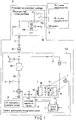
- FIG. 1 is a diagram showing the overall configuration of a power system including a variable-speed pumped storage power system according to the first embodiment.
- a power plant and a power plant switchgear P comprise a power plant high-voltage switchgear 100 connected to a grid system S, and a variable-speed pumped storage power system 200 connected to the power plant high-voltage switchgear 100 via a power cable C and a main transformer M.
- a low-voltage side of the main transformer M is equivalent to an internal circuit of the power plant.
- the main transformer M may be configured as a part of the variable-speed pumped storage power system.
- the power plant high-voltage switchgear 100 comprises breakers 101 and 102 which respectively open and close power lines connected to, for example, a No. 1 power transmission line and a No. 2 power transmission line on the side of the grid system S, and comprises a breaker 103 which opens and closes a power line connected to a power cable C on the high-voltage side of the main transformer M, and further comprises a high-voltage side circuit voltage detector 104 which detects a voltage of a high-voltage side circuit of the main transformer M.
- the variable-speed pumped storage power system comprises a pump turbine 1; a variable-speed generator-motor 2 obtained by a doubly-fed alternator; a self-excitation secondary exciter 3 (which may be referred to as an "AC exciter 3" or a “self-excitation converter 3") including a converter 3A and an inverter 3B obtained by a frequency converter which is connected to a secondary winding of the variable-speed generator-motor 2 and which applies a variable-frequency AC; a control device 4 which controls an AC voltage, a current, a frequency, and a phase output by the secondary exciter 3 and which controls the opening/closing of a parallel-in circuit breaker 5A and a phase inversion disconnector 5B; the parallel-in circuit breaker 5A and the phase inversion disconnector 5B used for connection of a stator winding side of the variable-speed generator-motor 2 to the grid system S; a start/brake disconnector 6 which causes three-phase short-circuiting at a stator winding terminal
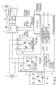
- FIG. 2 is a configuration diagram mainly showing a functional configuration related to a DC-interruption prevention device of the variable-speed pumped storage power system according to the present embodiment.
- the same reference numbers are given to the same components as those in FIG. 1 .
- the AC overvoltage suppression device 13 constitutes a resistor-equipped short-circuit device comprising thyristors 131 each connected between phases of a secondary winding of the variable-speed generator-motor 2, resistors 132 inserted between lines, and the current detector 12 which detects currents of the thyristors 131.
- a line-to-line voltage V2 of a secondary side AC circuit of the generator-motor or a voltage VD of the DC link circuit of the secondary exciter 3 exceeds a predetermined value, a gate signal which controls the firing of each of the thyristors 131 is applied to the AC overvoltage suppression device 13 from the control device 4.
- an ON gate signal which fires a self-excitation element such as an IGBT is applied to the DC overvoltage suppression device 14 from the control device 4, and when the voltage VD is less than or equal to the predetermined value as a result of the above operation, an OFF gate signal is applied to the DC overvoltage suppression device 14.
- the DC overvoltage suppression device 14 When both the AC overvoltage suppression device 13 and the DC overvoltage suppression device 14 are provided, the DC overvoltage suppression device 14 operates at a lower set value, and when the position of a grid system failure is far from the power plant or when a fault aspect is a single-phase ground fault and a fault current is relatively low, the DC overvoltage suppression device 14 suppresses a voltage rise to a voltage range in which the converter 3 is operable, and the normal operation of the generator-motor by the converter 3 is continued.
- a set value of the AC overvoltage suppression device 13 is set so that the AC overvoltage suppression device 13 operates when a voltage further rises even when the DC overvoltage suppression device 14 operates.
- the control device 4 stops supply of a normal operation gate signal supplied for the normal operation, supplies an ON gate signal to the AC overvoltage suppression device 13, and operates the three-phase short-circuit device by the thyristors 131.
- a fault current is quickly attenuated by the effect of the resistors 132 provided in a circuit of a three-phase short-circuit device by the thyristors 131, and when a current to the three-phase short-circuit device detected by the current detector 12 has become less than or equal to an operable current of the inverter 3B, a reverse current is applied to the thyristors 131 from the inverter 3B based on the reset control by the control device 4 (based on a reset operation gate signal supplied from the control device 4) to forcibly turn off the three-phase short-circuit device, and the normal operation of the generator-motor by the converter 3 is resumed.
- the control device 4 may perform the reset control on the AC overvoltage suppression device 13, for example, on a condition that the voltage of each phase of the low-voltage side circuit of the main transformer M (hereinafter "voltage VL") exceeds a predetermined value, from the viewpoint of obviating flowing of a current that may damage a circuit of, for example, the three-phase short-circuit device including a semiconductor element when the reset control is performed.
- voltage VL the voltage of each phase of the low-voltage side circuit of the main transformer M
- the generator-motor can be kept in operation without being stopped for protection.
- the resistors 132 are provided in the circuit of the short-circuit device of the AC overvoltage suppression device 13, the time constant of the generator-motor secondary circuit of the variable-speed generator-motor 2 is lower and an AC component of the generator-motor primary circuit attenuates extremely early when a grid system failure has occurred. Accordingly, a transient DC component may be increased depending on the occurrence timing of the grid system failure, and the fault current would not pass a zero point, resulting in failure of current interruption when the breaker 101, 102, or 103 positioned closer to the grid system or the parallel-in circuit breaker 5A in the power plant interrupts the fault current. In this case, the breaker may be damaged.
- a DC-interruption prevention device 15 is equipped with a short-circuit device 151 which is capable of executing three-phase short-circuiting in the three-phase circuit without any resistor by thyristors 151-1 each connected between phases of a secondary winding of the variable-speed generator-motor 2, the high-voltage side circuit voltage detector 104 which detects a voltage Vs of the high-voltage side circuit of the main transformer M and the low-voltage side circuit voltage detector 9 (corresponding to the aforementioned primary circuit voltage detector 9) which detects a voltage VL of the low-voltage side circuit of the main transformer M, and a DC-interruption avoidance control device (controller) 153.
- the DC-interruption avoidance control device 153 may be provided in the control device 4, instead of being provided in the DC-interruption prevention device 15.
- FIG. 3 An example of an internal configuration of the DC-interruption avoidance control device 153 of the DC-interruption prevention device 15 in FIG. 2 is shown in FIG. 3 .
- the DC-interruption avoidance control device 153 inputs a three-phase voltage on the high-voltage side of the main transformer obtained by the high-voltage side circuit voltage detector 104, finds a voltage vector in a calculator 153-1, and outputs the magnitude of the voltage vector to a threshold processing circuit 153-2.
- the threshold processing circuit 153-2 sets, for example, a voltage value required in a specification for operation continuity with the grid system S, if any, as a threshold of this voltage, and outputs a signal (e.g., a signal having a value "1") which instructs to operate the short-circuit device 151 of the DC-interruption prevention device 15 when the magnitude of the voltage vector is smaller than the threshold.
- a three-phase voltage of the low-voltage side circuit of the main transformer M obtained by the low-voltage side circuit voltage detector 9 is further input, a voltage vector is found in a calculator 153-3, and the magnitude of the voltage vector is output to a threshold processing circuit 153-4.
- the threshold processing circuit 153-4 sets, as a threshold VL0, a voltage value of the low-voltage side circuit corresponding to the voltage value of the high-voltage side circuit of the main transformer M required in, for example, a specification for operation continuity with the grid system S, and outputs a signal (e.g., a signal having a value "1") which instructs to operate the short-circuit device 151 of the DC-interruption prevention device 15 when the magnitude of the voltage vector is smaller than the threshold.
- a signal e.g., a signal having a value "1
- An OR circuit 153-5 outputs an ON gate signal to the short-circuit device 151 of the DC-interruption prevention device 15 from the DC-interruption avoidance control device 153 if at least one of the two outputs is "1", so that the thyristors are brought to a conducting state, and the generator-motor secondary circuit is short-circuited without any resistor. This operation is much earlier than the operation to interrupt the fault current by the breaker 103 or 5A, and can be performed substantially simultaneously with the operations of the overvoltage suppression devices 13 and 14.
- a current bypasses the interline resistors in the overvoltage suppression devices 13 and 14, so that it is possible to avoid the DC-interruption by preventing reduction of the time constant of the generator-motor secondary circuit, and ensuring an AC component which is sufficient for the fault current in the generator-motor primary circuit to pass the current zero point when the breaker 103 or 5A is opened.
- each of the thresholds of the threshold processing circuits 153-2 and 153-4 to a voltage value requesting the continuation of the operation or a lower value, it is possible to ensure the operation continuity by the overvoltage suppression devices 13 and 14 having the resistor-equipped short-circuit devices when a grid system failure has occurred, and for a major fault of the fault current which does not require the continuation of operation, it is possible to cause the DC-interruption prevention device 15 having the no-resistor short-circuit device 151 to operate such that the DC-interruption of the breaker is avoided and the variable-speed pumped storage power system is safely stopped. Consequently, it is possible to implement the converter 3 having a proper capacity needed for the continuation of operation.
- the ON gate signal of the short-circuit device of the DC-interruption prevention device 15 is reset by a circuit 153-6 in response to the disconnection of the parallel-in circuit breaker 5A, and can prepare for the next operation.
- this embodiment is not limited to the case where the no-resistor short-circuit device 151 of the DC-interruption prevention device 15 has no resistor.
- the no-resistor short-circuit device 151 of the DC-interruption prevention device 15 has resistors with resistance that assures that the DC time constant of the generator-motor primary circuit during the operation of the short-circuit device is lower than the DC time constant of the generator-motor secondary circuit.
- both delta connection and Y-connection are acceptable as long as the circuit configuration of the short-circuit device has a small resistor intervening between lines.
- FIG. 4 is a graph showing an example of a current waveform observed at the generator-motor primary circuit according to a configuration of the conventional technique in which the breaker of the generator-motor primary circuit causes a DC-interruption upon the occurrence of the three-phase short-circuit fault in the low-voltage side circuit of the main transformer M.
- FIG. 5 is a graph showing an example of a current waveform observed at the generator-motor primary circuit according to the present embodiment in which the DC-interruption prevention device is applied so as not to cause a DC-interruption upon the occurrence of the three-phase short-circuit fault.
- a-phase current In each of the current waveform charts, an a-phase current, a b-phase current, and a c-phase current that constitute the current of the generator-motor primary circuit on the occurrence of the fault are shown.
- the vertical axis indicates the current of the generator-motor primary circuit
- the horizontal axis indicates time.
- the current of the generator-motor primary circuit has a great attenuation amount of the AC component, and most of the AC component has already attenuated, for example, in five cycles of parallel-in circuit breaker shut-off timing.
- the remaining transient DC component current which composes the current of the generator-motor primary circuit, does not pass the zero point, resulting in failure of current interruption.
- the a-phase current is observed.
- a current for the a-phase component is much higher than a rated current peak value, does not pass the zero point, and cannot be safely interrupted. If the a-phase current is interrupted, the direct-current is interrupted, and the breaker is damaged. The same also applies to the b-phase current and the c-phase current.
- the parallel-in circuit breaker 5A when the parallel-in circuit breaker 5A is specified to open at a point of 100 [ms], the current of each phase does not pass the zero point before this point. Moreover, when the breaker 101, 102, or 103 positioned closer to the grid system are specified to open within three cycles (60 [ms]) after the fault in the case of a grid system failure, the current of each phase does not pass the zero point before this point. There is concern that a DC-interruption may occur and the breaker may be damaged unless the current crosses the zero point, but the example of FIG. 4 cannot cope with such a problem.
- the current of the generator-motor primary circuit has a small attenuation amount of the AC component, and the AC component hardly attenuates, for example, even in five cycles of the parallel-in circuit breaker shut-off timing.
- the current bypasses the interline resistors in the overvoltage suppression devices 13 and 14 due to the effect of the DC-interruption prevention device 15, so that the time constant of the generator-motor secondary circuit is increased, and the attenuation of the AC component is delayed.
- the DC component can be kept greater than the AC component because attenuation of the AC component is delayed. This ensures that all of the a-phase current, the b-phase current, and the c-phase current of the current of the generator-motor primary circuit can pass the zero point, so that the DC-interruption can be avoided, while current interruption can be successful.
- the current of each phase passes the zero point more than once before this point in the example of FIG. 5 , so that it is possible to safely perform current interruption without damaging the breakers.
- the DC-interruption avoidance control device 153 causes the short-circuit device 151 to execute three-phase short-circuiting on a condition that at least one of the output voltage of the high-voltage side circuit voltage detector 104 and the output voltage of the low-voltage side circuit voltage detector 9 becomes lower than each predetermined value in the example shown in the embodiment described above, this example is not restrictive.
- the short-circuit device 151 may be caused to execute three-phase short-circuiting on a condition that the output voltage of the high-voltage side circuit voltage detector 104 becomes lower than the predetermined value.
- the short-circuit device 151 may be caused to execute three-phase short-circuiting on a condition that the output voltage of the low-voltage side circuit voltage detector 9 becomes lower than the predetermined value.
- a current of a rotor winding of the variable-speed generator-motor 2 may be used instead of the output voltage of the high-voltage side circuit voltage detector 104 and the output voltage of the low-voltage side circuit voltage detector 9 to determine whether or not a condition that the short-circuit device 151 is caused to execute three-phase short-circuiting is satisfied.
- a current of a stator winding side circuit may be used.
- a rotor winding current detector which detects the current of the rotor winding or a stator winding current detector which detects the current of the stator winding side circuit can be provided so that the short-circuit device 151 is caused to execute three-phase short-circuiting on a condition that the current detected by the rotor winding current detector or the stator winding current detector is not less than or equal to each prescribed current value.
- information or a signal indicating the occurrence place of a fault may be used instead of the output voltage of the high-voltage side circuit voltage detector 104 and the output voltage of the low-voltage side circuit voltage detector 9 to determine whether or not a condition that the short-circuit device 151 is caused to execute three-phase short-circuiting is satisfied.
- the short-circuit device 151 may be caused to execute three-phase short-circuiting on a condition that there is no operation of a predetermined protective relay.
- variable-speed pumped storage power system which ensures the continuity of operation connecting the variable-speed pumped storage power system with the grid system even when a grid system failure has occurred, and which prevents a DC-interruption by a breaker.
Landscapes
- Engineering & Computer Science (AREA)
- Power Engineering (AREA)
- Control Of Eletrric Generators (AREA)
- Emergency Protection Circuit Devices (AREA)
Claims (4)
- Drehzahlvariables Pumpspeicherkraftwerksystem (200), das durch mindestens einen Unterbrecher (101, 102 und/oder 103) über einen Transformator (M) mit einem Netzsystem (S) verbunden ist und jeweils mit einem doppelt gespeisten drehzahlvariablen Generator-Motor (2), der eine Statorwicklung aufweist, die über einen parallelen kreisinternen Unterbrecher (5A) mit einer Niederspannungsseite des Transformators (M) verbunden ist, einem Kreisspannungsdetektor (104) auf einer Hochspannungsseite, einem Kreisspannungsdetektor (9) auf einer Niederspannungsseite undi) einer Wechselstrom-Überspannungsunterdrückungsvorrichtung, die mit einem Drehstromkreis zwischen einem Wechselstromerreger (3) und einer Rotorwicklung des doppelt gespeisten drehzahlvariablen Generator-Motors (2) verbunden ist, und/oderii) einer Gleichstrom-Überspannungsunterdrückungsvorrichtung versehen ist, die mit einem Wechselstromverbindungskreis in dem Wechselstromerreger (3) verbunden ist,und die ausgestaltet sind, um ein Kurzschließen der verbundenen Kreise über Widerstände auszuführen, wenn eine Überspannung in mindestens einem von den verbundenen Kreisen aufgetreten ist, dadurch gekennzeichnet, dass das drehzahlvariable Pumpspeicherkraftwerksystem eine Gleichstrom-Unterbrechungsverhinderungsvorrichtung (15) zum Vermeiden einer Gleichstromunterbrechung an einem der Unterbrecher beim Auftreten eines Fehlers umfasst, wobei die Gleichstrom-Unterbrechungsverhinderungsvorrichtung mindestens umfasst:eine Kurzschlussvorrichtung (151), die mit dem Drehstromkreis zwischen der Rotorwicklung und dem Wechselstromerreger (3) verbunden ist und eingerichtet ist, um Drehstromkurzschließen des verbundenen Kreises auszuführen; undeine Steuereinrichtung (153), die dazu ausgestaltet ist, zu bewirken, dass die Kurzschlussvorrichtung (151) Drehstromkurzschließen unter einer Bedingung ausführt, dass mindestens eines von einer Ausgangsspannung des Kreisspannungsdetektors (104) auf der Hochspannungsseite und einer Ausgangsspannung des Kreisspannungsdetektors (9) auf der Niederspannungsseite niedriger als ein entsprechender vorbestimmter Wert wird.
- Drehzahlvariables Pumpspeicherkraftwerksystem (200) nach Anspruch 1, wobei die Gleichstrom-Unterbrechungsverhinderungsvorrichtung (15) umfasst:
anstatt der Kurzschlussvorrichtung (151), die in der Lage ist Drehstromkurzschließen des verbundenen Kreises auszuführen, eine Kurzschlussvorrichtung (151), die mit dem Drehstromkreis zwischen der Rotorwicklung und dem Wechselstromerreger (3) verbunden ist und in der Lage ist, Drehstromkurzschließen des verbundenen Kreises über Widerstände (r) zwischen Phasen mit Widerstand auszuführen, wodurch sichergestellt wird, dass während des Betriebs der Kurzschlussvorrichtung (151) die Gleichstrom-Zeitkonstante des Generator-Motor-Hauptkreises niedriger als die Gleichstrom-Zeitkonstante des Generator-Motor-Nebenkreises ist. - Drehzahlvariables Pumpspeicherkraftverfahren, das auf ein drehzahlvariables Pumpspeicherkraftwerksystem (200) angewandt wird, das durch mindestens einen Unterbrecher (101, 102 und/oder 103) über einen Transformator (M) mit einem Netzsystem (S) verbunden ist und jeweils mit einem doppelt gespeisten drehzahlvariablen Generator-Motor (2), der eine Statorwicklung aufweist, die über einen parallelen kreisinternen Unterbrecher (5A) mit einer Niederspannungsseite des Transformators (M) verbunden ist, einem Kreisspannungsdetektor (104) auf der Hochspannungsseite, einem Kreisspannungsdetektor (9) auf einer Niederspannungsseite,i) einer Wechselstrom-Überspannungsunterdrückungsvorrichtung, die mit einem Drehstromkreis zwischen einem Wechselstromerreger (3) und einer Rotorwicklung des doppelt gespeisten drehzahlvariablen Generator-Motors (2) verbunden ist, undii) einer Gleichstrom-Überspannungsunterdrückungsvorrichtung versehen ist, die mit einem Wechselstromverbindungskreis in dem Wechselstromerreger (3) verbunden ist,und die ausgestaltet sind, um ein Kurzschließen der verbundenen Kreise über Widerstände auszuführen, wenn eine Überspannung in mindestens einem von den verbundenen Kreisen aufgetreten ist, wobei das drehzahlvariable Pumpspeicherkraftverfahren, dadurch gekennzeichnet ist, dass es umfasst:Bereitstellen einer Gleichstrom-Unterbrechungsverhinderungsvorrichtung (15), derart, dass beim Auftreten eines Fehlers keine Gleichstromunterbrechung durch einen beliebigen von jenen Unterbrechern verursacht wird, wobei die Gleichstrom-Unterbrechungsverhinderungsvorrichtung mindestens eine Kurzschlussvorrichtung (151) umfasst, die mit dem Drehstromkreis zwischen der Rotorwicklung und dem Wechselstromerreger (3) verbunden ist und eingerichtet ist, um Drehstromkurzschließen der verbundenen Schaltung auszuführen; undBewirken, dass die Kurzschlussvorrichtung (151) Drehstromkurzschließen durch eine Steuereinrichtung (153) unter einer Bedingung ausführt, dass mindestens eines von einer Ausgangsspannung des Kreisspannungsdetektors (104) auf der Hochspannungsseite und einer Ausgangsspannung des Kreisspannungsdetektors (9) auf der Niederspannungsseite niedriger als ein entsprechender vorbestimmter Wert wird.
- Drehzahlvariables Pumpspeicherkraftverfahren nach Anspruch 3, das das Bereitstellen, in der Gleichstrom-Unterbrechungsverhinderungsvorrichtung (15), anstatt der Kurzschlussvorrichtung (151), die in der Lage ist, Drehstromkurzschließen des verbundenen Kreises auszuführen, einer Kurzschlussvorrichtung (151) umfasst, die mit dem Drehstromkreis zwischen der Rotorwicklung und dem Wechselstromerreger (3) verbunden ist und in der Lage ist, Drehstromkurzschließen des verbundenen Kreises über Widerstände (r) zwischen Phasen mit Widerstand auszuführen, wodurch sicherstellt wird, dass während des Betriebs der Kurzschlussvorrichtung (151) die Gleichstrom-Zeitkonstante des Generator-Motor-Hauptkreises niedriger ist als die Gleichstrom-Zeitkonstante des Generator-Motor-Nebenkreises.
Applications Claiming Priority (2)
| Application Number | Priority Date | Filing Date | Title |
|---|---|---|---|
| JP2017060074 | 2017-03-24 | ||
| JP2018016518A JP6371021B1 (ja) | 2017-03-24 | 2018-02-01 | 可変速揚水発電システムおよび可変速揚水発電方法 |
Publications (3)
| Publication Number | Publication Date |
|---|---|
| EP3379717A2 EP3379717A2 (de) | 2018-09-26 |
| EP3379717A3 EP3379717A3 (de) | 2018-12-19 |
| EP3379717B1 true EP3379717B1 (de) | 2021-07-28 |
Family
ID=63104332
Family Applications (1)
| Application Number | Title | Priority Date | Filing Date |
|---|---|---|---|
| EP18159620.6A Active EP3379717B1 (de) | 2017-03-24 | 2018-03-02 | Drehzahlvariables pumpspeicherkraftwerk und drehzahlvariables pumpspeicherkraftverfahren |
Country Status (3)
| Country | Link |
|---|---|
| EP (1) | EP3379717B1 (de) |
| JP (1) | JP6371021B1 (de) |
| CN (1) | CN108631264B (de) |
Families Citing this family (5)
| Publication number | Priority date | Publication date | Assignee | Title |
|---|---|---|---|---|
| CN112039377B (zh) * | 2019-06-04 | 2023-04-18 | 西安许继电力电子技术有限公司 | 一种变速抽水蓄能机组的自启动、制动方法及装置 |
| FR3103228B1 (fr) * | 2019-11-15 | 2021-10-29 | Valeo Equip Electr Moteur | Module de contrôle et procédé de gestion de fin de mode moteur pour une machine electrique tournante |
| CN114002614B (zh) * | 2020-07-28 | 2024-10-22 | 南京南瑞继保电气有限公司 | 变速抽水蓄能机组转子绕组单相接地故障的判别方法 |
| CN114244212A (zh) * | 2020-12-22 | 2022-03-25 | 熵零技术逻辑工程院集团股份有限公司 | 一种发电机组起动方法 |
| CN113098039B (zh) * | 2021-03-04 | 2022-04-15 | 清华大学 | 基于飞轮储能可变速抽水蓄能机组的动能回收系统及方法 |
Family Cites Families (16)
| Publication number | Priority date | Publication date | Assignee | Title |
|---|---|---|---|---|
| US4041543A (en) * | 1975-03-25 | 1977-08-09 | Westinghouse Electric Corporation | Field protector for synchronous machines |
| SU1584058A1 (ru) * | 1988-01-13 | 1990-08-07 | Центральное Проектно-Конструкторское И Технологическое Бюро Крупных Электрических Машин | Электропривод переменного тока |
| JP3100805B2 (ja) * | 1993-08-24 | 2000-10-23 | 東京電力株式会社 | 可変速揚水発電システムの過電圧保護装置 |
| JP3277047B2 (ja) * | 1993-10-12 | 2002-04-22 | 東京電力株式会社 | 過電圧保護回路 |
| JPH08317694A (ja) * | 1995-05-19 | 1996-11-29 | Tokyo Electric Power Co Inc:The | 過電圧保護装置 |
| JPH11215896A (ja) * | 1998-01-22 | 1999-08-06 | Mitsubishi Electric Corp | 可変速発電電動機の過電圧抑制装置 |
| JP2001178195A (ja) * | 1999-12-20 | 2001-06-29 | Toshiba Corp | 発電装置 |
| JP2007236059A (ja) * | 2006-02-28 | 2007-09-13 | Chugoku Electric Power Co Inc:The | 電力系統の保護継電システム、電力系統の保護方法 |
| JP5713788B2 (ja) * | 2011-04-28 | 2015-05-07 | 株式会社東芝 | 制御装置および可変速発電電動機始動方法 |
| WO2013071937A1 (en) * | 2011-11-16 | 2013-05-23 | Vestas Wind Systems A/S | Protection of a permanent magnet generator |
| CN102522777A (zh) * | 2011-12-27 | 2012-06-27 | 东方电气集团东方汽轮机有限公司 | 一种风力发电机组 |
| CN102999675B (zh) * | 2012-12-12 | 2015-04-08 | 上海市电力公司 | 双馈变速恒频风电机组系统电磁暂态仿真方法 |
| EP2830176B1 (de) * | 2013-07-25 | 2017-02-22 | General Electric Technology GmbH | Variables fenster-rms-basiertes schutzsystem und -verfahren für eine doppelt eingespeiste induktionsmaschine mit elektrisch variabler drehzahl |
| JP6071912B2 (ja) * | 2014-01-27 | 2017-02-01 | 株式会社東芝 | 過電圧保護装置および電流調整回路 |
| JP6158109B2 (ja) * | 2014-02-07 | 2017-07-05 | 株式会社東芝 | 過電圧保護装置 |
| CN106150900A (zh) * | 2016-06-30 | 2016-11-23 | 华仪风能有限公司 | 双馈‑异步风力发电系统及其运行方法 |
-
2018
- 2018-02-01 JP JP2018016518A patent/JP6371021B1/ja active Active
- 2018-02-26 CN CN201810158899.8A patent/CN108631264B/zh active Active
- 2018-03-02 EP EP18159620.6A patent/EP3379717B1/de active Active
Non-Patent Citations (1)
| Title |
|---|
| None * |
Also Published As
| Publication number | Publication date |
|---|---|
| EP3379717A3 (de) | 2018-12-19 |
| CN108631264B (zh) | 2020-03-20 |
| CN108631264A (zh) | 2018-10-09 |
| JP6371021B1 (ja) | 2018-08-08 |
| JP2018164393A (ja) | 2018-10-18 |
| EP3379717A2 (de) | 2018-09-26 |
Similar Documents
| Publication | Publication Date | Title |
|---|---|---|
| EP3379717A2 (de) | Drehzahlvariables pumpspeicherkraftwerk und drehzahlvariables pumpspeicherkraftverfahren | |
| CN104488156B (zh) | 故障排除的方法 | |
| US11962142B2 (en) | Power distribution system for moving body | |
| CN107611937B (zh) | 一种直流断路器的过电压保护电路及方法 | |
| CN103597733B (zh) | 用于保护电压源转换器的方法和控制器 | |
| WO2019119886A1 (zh) | 一种串联补偿器及控制方法 | |
| KR20060036454A (ko) | 이중 권선형 유도 발전기 시스템의 제어 및 보호 | |
| Liu et al. | Protection of single-phase fault at the transformer valve side of FB-MMC-based bipolar HVdc systems | |
| CN105449650A (zh) | 一种柔性直流智能输配电网的保护系统和方法 | |
| CN102412568B (zh) | 调整线路保护动作时序解决断路器电流延迟过零的方法 | |
| CN104836206A (zh) | 过电压保护装置 | |
| JP6029993B2 (ja) | 静止形周波数変換電源装置 | |
| KR101622187B1 (ko) | 한류기 | |
| Mohanty et al. | Current restrained undervoltage protection scheme of converter dominated microgrids | |
| JP2017184337A (ja) | 可変速揚水発電システムの過電圧保護装置 | |
| EP3547476B1 (de) | Überspannungsschutzvorrichtung eines stromerzeugungssystems mit variabler geschwindigkeit | |
| CN205595755U (zh) | 一种高压电路继电保护系统 | |
| JP3286049B2 (ja) | 可変速発電システム | |
| JP7615012B2 (ja) | 変圧器の制御装置 | |
| WO1999009631A1 (fr) | Dispositif d'interconnexion de systeme et alimentation decentralisee equipee d'un tel dispositif et pourvue d'une fonction de prevention de la chute de tension instantanee | |
| JP6431777B2 (ja) | 電力変換器 | |
| CN116316431B (zh) | 一种机端断路器非全相保护方法及装置 | |
| SE445598B (sv) | Skyddsanordning for en styrbar vexelriktare i en frekvensomformare | |
| WO2020121466A1 (ja) | 電力供給システムおよび電力供給方法 | |
| CN110277764B (zh) | 一种电网过压保护电路和方法 |
Legal Events
| Date | Code | Title | Description |
|---|---|---|---|
| PUAI | Public reference made under article 153(3) epc to a published international application that has entered the european phase |
Free format text: ORIGINAL CODE: 0009012 |
|
| STAA | Information on the status of an ep patent application or granted ep patent |
Free format text: STATUS: REQUEST FOR EXAMINATION WAS MADE |
|
| 17P | Request for examination filed |
Effective date: 20180302 |
|
| AK | Designated contracting states |
Kind code of ref document: A2 Designated state(s): AL AT BE BG CH CY CZ DE DK EE ES FI FR GB GR HR HU IE IS IT LI LT LU LV MC MK MT NL NO PL PT RO RS SE SI SK SM TR |
|
| AX | Request for extension of the european patent |
Extension state: BA ME |
|
| PUAL | Search report despatched |
Free format text: ORIGINAL CODE: 0009013 |
|
| AK | Designated contracting states |
Kind code of ref document: A3 Designated state(s): AL AT BE BG CH CY CZ DE DK EE ES FI FR GB GR HR HU IE IS IT LI LT LU LV MC MK MT NL NO PL PT RO RS SE SI SK SM TR |
|
| AX | Request for extension of the european patent |
Extension state: BA ME |
|
| RIC1 | Information provided on ipc code assigned before grant |
Ipc: H02H 7/09 20060101ALN20181109BHEP Ipc: H02P 9/00 20060101ALI20181109BHEP Ipc: H02P 9/10 20060101AFI20181109BHEP |
|
| STAA | Information on the status of an ep patent application or granted ep patent |
Free format text: STATUS: EXAMINATION IS IN PROGRESS |
|
| 17Q | First examination report despatched |
Effective date: 20190909 |
|
| RIC1 | Information provided on ipc code assigned before grant |
Ipc: H02H 7/12 20060101ALI20210118BHEP Ipc: H02H 9/04 20060101ALI20210118BHEP Ipc: H02H 7/09 20060101ALN20210118BHEP Ipc: H02P 9/00 20060101ALI20210118BHEP Ipc: H02P 9/10 20060101AFI20210118BHEP |
|
| GRAP | Despatch of communication of intention to grant a patent |
Free format text: ORIGINAL CODE: EPIDOSNIGR1 |
|
| STAA | Information on the status of an ep patent application or granted ep patent |
Free format text: STATUS: GRANT OF PATENT IS INTENDED |
|
| RIC1 | Information provided on ipc code assigned before grant |
Ipc: H02H 7/12 20060101ALI20210201BHEP Ipc: H02P 9/10 20060101AFI20210201BHEP Ipc: H02H 7/09 20060101ALN20210201BHEP Ipc: H02H 9/04 20060101ALI20210201BHEP Ipc: H02P 9/00 20060101ALI20210201BHEP |
|
| RIC1 | Information provided on ipc code assigned before grant |
Ipc: H02H 7/12 20060101ALI20210218BHEP Ipc: H02P 9/10 20060101AFI20210218BHEP Ipc: H02P 9/00 20060101ALI20210218BHEP Ipc: H02H 7/09 20060101ALN20210218BHEP Ipc: H02H 9/04 20060101ALI20210218BHEP |
|
| INTG | Intention to grant announced |
Effective date: 20210304 |
|
| RAP3 | Party data changed (applicant data changed or rights of an application transferred) |
Owner name: KABUSHIKI KAISHA TOSHIBA Owner name: TOSHIBA ENERGY SYSTEMS & SOLUTIONS CORPORATION |
|
| GRAS | Grant fee paid |
Free format text: ORIGINAL CODE: EPIDOSNIGR3 |
|
| GRAA | (expected) grant |
Free format text: ORIGINAL CODE: 0009210 |
|
| STAA | Information on the status of an ep patent application or granted ep patent |
Free format text: STATUS: THE PATENT HAS BEEN GRANTED |
|
| AK | Designated contracting states |
Kind code of ref document: B1 Designated state(s): AL AT BE BG CH CY CZ DE DK EE ES FI FR GB GR HR HU IE IS IT LI LT LU LV MC MK MT NL NO PL PT RO RS SE SI SK SM TR |
|
| REG | Reference to a national code |
Ref country code: GB Ref legal event code: FG4D |
|
| REG | Reference to a national code |
Ref country code: CH Ref legal event code: EP |
|
| REG | Reference to a national code |
Ref country code: DE Ref legal event code: R096 Ref document number: 602018020645 Country of ref document: DE |
|
| REG | Reference to a national code |
Ref country code: AT Ref legal event code: REF Ref document number: 1415630 Country of ref document: AT Kind code of ref document: T Effective date: 20210815 |
|
| REG | Reference to a national code |
Ref country code: IE Ref legal event code: FG4D |
|
| REG | Reference to a national code |
Ref country code: LT Ref legal event code: MG9D |
|
| REG | Reference to a national code |
Ref country code: NL Ref legal event code: MP Effective date: 20210728 |
|
| PG25 | Lapsed in a contracting state [announced via postgrant information from national office to epo] |
Ref country code: SE Free format text: LAPSE BECAUSE OF FAILURE TO SUBMIT A TRANSLATION OF THE DESCRIPTION OR TO PAY THE FEE WITHIN THE PRESCRIBED TIME-LIMIT Effective date: 20210728 Ref country code: RS Free format text: LAPSE BECAUSE OF FAILURE TO SUBMIT A TRANSLATION OF THE DESCRIPTION OR TO PAY THE FEE WITHIN THE PRESCRIBED TIME-LIMIT Effective date: 20210728 Ref country code: HR Free format text: LAPSE BECAUSE OF FAILURE TO SUBMIT A TRANSLATION OF THE DESCRIPTION OR TO PAY THE FEE WITHIN THE PRESCRIBED TIME-LIMIT Effective date: 20210728 Ref country code: ES Free format text: LAPSE BECAUSE OF FAILURE TO SUBMIT A TRANSLATION OF THE DESCRIPTION OR TO PAY THE FEE WITHIN THE PRESCRIBED TIME-LIMIT Effective date: 20210728 Ref country code: FI Free format text: LAPSE BECAUSE OF FAILURE TO SUBMIT A TRANSLATION OF THE DESCRIPTION OR TO PAY THE FEE WITHIN THE PRESCRIBED TIME-LIMIT Effective date: 20210728 Ref country code: LT Free format text: LAPSE BECAUSE OF FAILURE TO SUBMIT A TRANSLATION OF THE DESCRIPTION OR TO PAY THE FEE WITHIN THE PRESCRIBED TIME-LIMIT Effective date: 20210728 Ref country code: BG Free format text: LAPSE BECAUSE OF FAILURE TO SUBMIT A TRANSLATION OF THE DESCRIPTION OR TO PAY THE FEE WITHIN THE PRESCRIBED TIME-LIMIT Effective date: 20211028 Ref country code: NL Free format text: LAPSE BECAUSE OF FAILURE TO SUBMIT A TRANSLATION OF THE DESCRIPTION OR TO PAY THE FEE WITHIN THE PRESCRIBED TIME-LIMIT Effective date: 20210728 Ref country code: NO Free format text: LAPSE BECAUSE OF FAILURE TO SUBMIT A TRANSLATION OF THE DESCRIPTION OR TO PAY THE FEE WITHIN THE PRESCRIBED TIME-LIMIT Effective date: 20211028 Ref country code: PT Free format text: LAPSE BECAUSE OF FAILURE TO SUBMIT A TRANSLATION OF THE DESCRIPTION OR TO PAY THE FEE WITHIN THE PRESCRIBED TIME-LIMIT Effective date: 20211129 |
|
| PG25 | Lapsed in a contracting state [announced via postgrant information from national office to epo] |
Ref country code: PL Free format text: LAPSE BECAUSE OF FAILURE TO SUBMIT A TRANSLATION OF THE DESCRIPTION OR TO PAY THE FEE WITHIN THE PRESCRIBED TIME-LIMIT Effective date: 20210728 Ref country code: LV Free format text: LAPSE BECAUSE OF FAILURE TO SUBMIT A TRANSLATION OF THE DESCRIPTION OR TO PAY THE FEE WITHIN THE PRESCRIBED TIME-LIMIT Effective date: 20210728 Ref country code: GR Free format text: LAPSE BECAUSE OF FAILURE TO SUBMIT A TRANSLATION OF THE DESCRIPTION OR TO PAY THE FEE WITHIN THE PRESCRIBED TIME-LIMIT Effective date: 20211029 |
|
| PG25 | Lapsed in a contracting state [announced via postgrant information from national office to epo] |
Ref country code: DK Free format text: LAPSE BECAUSE OF FAILURE TO SUBMIT A TRANSLATION OF THE DESCRIPTION OR TO PAY THE FEE WITHIN THE PRESCRIBED TIME-LIMIT Effective date: 20210728 |
|
| REG | Reference to a national code |
Ref country code: DE Ref legal event code: R097 Ref document number: 602018020645 Country of ref document: DE |
|
| PG25 | Lapsed in a contracting state [announced via postgrant information from national office to epo] |
Ref country code: SM Free format text: LAPSE BECAUSE OF FAILURE TO SUBMIT A TRANSLATION OF THE DESCRIPTION OR TO PAY THE FEE WITHIN THE PRESCRIBED TIME-LIMIT Effective date: 20210728 Ref country code: SK Free format text: LAPSE BECAUSE OF FAILURE TO SUBMIT A TRANSLATION OF THE DESCRIPTION OR TO PAY THE FEE WITHIN THE PRESCRIBED TIME-LIMIT Effective date: 20210728 Ref country code: RO Free format text: LAPSE BECAUSE OF FAILURE TO SUBMIT A TRANSLATION OF THE DESCRIPTION OR TO PAY THE FEE WITHIN THE PRESCRIBED TIME-LIMIT Effective date: 20210728 Ref country code: EE Free format text: LAPSE BECAUSE OF FAILURE TO SUBMIT A TRANSLATION OF THE DESCRIPTION OR TO PAY THE FEE WITHIN THE PRESCRIBED TIME-LIMIT Effective date: 20210728 Ref country code: CZ Free format text: LAPSE BECAUSE OF FAILURE TO SUBMIT A TRANSLATION OF THE DESCRIPTION OR TO PAY THE FEE WITHIN THE PRESCRIBED TIME-LIMIT Effective date: 20210728 Ref country code: AL Free format text: LAPSE BECAUSE OF FAILURE TO SUBMIT A TRANSLATION OF THE DESCRIPTION OR TO PAY THE FEE WITHIN THE PRESCRIBED TIME-LIMIT Effective date: 20210728 |
|
| PLBE | No opposition filed within time limit |
Free format text: ORIGINAL CODE: 0009261 |
|
| STAA | Information on the status of an ep patent application or granted ep patent |
Free format text: STATUS: NO OPPOSITION FILED WITHIN TIME LIMIT |
|
| REG | Reference to a national code |
Ref country code: AT Ref legal event code: UEP Ref document number: 1415630 Country of ref document: AT Kind code of ref document: T Effective date: 20210728 |
|
| 26N | No opposition filed |
Effective date: 20220429 |
|
| PG25 | Lapsed in a contracting state [announced via postgrant information from national office to epo] |
Ref country code: IT Free format text: LAPSE BECAUSE OF FAILURE TO SUBMIT A TRANSLATION OF THE DESCRIPTION OR TO PAY THE FEE WITHIN THE PRESCRIBED TIME-LIMIT Effective date: 20210728 |
|
| PG25 | Lapsed in a contracting state [announced via postgrant information from national office to epo] |
Ref country code: MC Free format text: LAPSE BECAUSE OF FAILURE TO SUBMIT A TRANSLATION OF THE DESCRIPTION OR TO PAY THE FEE WITHIN THE PRESCRIBED TIME-LIMIT Effective date: 20210728 |
|
| GBPC | Gb: european patent ceased through non-payment of renewal fee |
Effective date: 20220302 |
|
| REG | Reference to a national code |
Ref country code: BE Ref legal event code: MM Effective date: 20220331 |
|
| PG25 | Lapsed in a contracting state [announced via postgrant information from national office to epo] |
Ref country code: LU Free format text: LAPSE BECAUSE OF NON-PAYMENT OF DUE FEES Effective date: 20220302 Ref country code: IE Free format text: LAPSE BECAUSE OF NON-PAYMENT OF DUE FEES Effective date: 20220302 Ref country code: GB Free format text: LAPSE BECAUSE OF NON-PAYMENT OF DUE FEES Effective date: 20220302 |
|
| PG25 | Lapsed in a contracting state [announced via postgrant information from national office to epo] |
Ref country code: BE Free format text: LAPSE BECAUSE OF NON-PAYMENT OF DUE FEES Effective date: 20220331 |
|
| PGFP | Annual fee paid to national office [announced via postgrant information from national office to epo] |
Ref country code: FR Payment date: 20231229 Year of fee payment: 7 |
|
| PG25 | Lapsed in a contracting state [announced via postgrant information from national office to epo] |
Ref country code: HU Free format text: LAPSE BECAUSE OF FAILURE TO SUBMIT A TRANSLATION OF THE DESCRIPTION OR TO PAY THE FEE WITHIN THE PRESCRIBED TIME-LIMIT; INVALID AB INITIO Effective date: 20180302 |
|
| PGFP | Annual fee paid to national office [announced via postgrant information from national office to epo] |
Ref country code: AT Payment date: 20240226 Year of fee payment: 7 |
|
| PG25 | Lapsed in a contracting state [announced via postgrant information from national office to epo] |
Ref country code: MK Free format text: LAPSE BECAUSE OF FAILURE TO SUBMIT A TRANSLATION OF THE DESCRIPTION OR TO PAY THE FEE WITHIN THE PRESCRIBED TIME-LIMIT Effective date: 20210728 Ref country code: CY Free format text: LAPSE BECAUSE OF FAILURE TO SUBMIT A TRANSLATION OF THE DESCRIPTION OR TO PAY THE FEE WITHIN THE PRESCRIBED TIME-LIMIT Effective date: 20210728 |
|
| PG25 | Lapsed in a contracting state [announced via postgrant information from national office to epo] |
Ref country code: MT Free format text: LAPSE BECAUSE OF FAILURE TO SUBMIT A TRANSLATION OF THE DESCRIPTION OR TO PAY THE FEE WITHIN THE PRESCRIBED TIME-LIMIT Effective date: 20210728 |
|
| PGFP | Annual fee paid to national office [announced via postgrant information from national office to epo] |
Ref country code: CH Payment date: 20250401 Year of fee payment: 8 |
|
| REG | Reference to a national code |
Ref country code: AT Ref legal event code: MM01 Ref document number: 1415630 Country of ref document: AT Kind code of ref document: T Effective date: 20250302 |
|
| PG25 | Lapsed in a contracting state [announced via postgrant information from national office to epo] |
Ref country code: TR Free format text: LAPSE BECAUSE OF FAILURE TO SUBMIT A TRANSLATION OF THE DESCRIPTION OR TO PAY THE FEE WITHIN THE PRESCRIBED TIME-LIMIT Effective date: 20210728 |
|
| PG25 | Lapsed in a contracting state [announced via postgrant information from national office to epo] |
Ref country code: AT Free format text: LAPSE BECAUSE OF NON-PAYMENT OF DUE FEES Effective date: 20250302 |
|
| PG25 | Lapsed in a contracting state [announced via postgrant information from national office to epo] |
Ref country code: FR Free format text: LAPSE BECAUSE OF NON-PAYMENT OF DUE FEES Effective date: 20250331 |
|
| REG | Reference to a national code |
Ref country code: CH Ref legal event code: U11 Free format text: ST27 STATUS EVENT CODE: U-0-0-U10-U11 (AS PROVIDED BY THE NATIONAL OFFICE) Effective date: 20260401 |
|
| PGFP | Annual fee paid to national office [announced via postgrant information from national office to epo] |
Ref country code: DE Payment date: 20260102 Year of fee payment: 9 |