EP3378299A1 - Landwirtschaftliches terminal - Google Patents
Landwirtschaftliches terminal Download PDFInfo
- Publication number
- EP3378299A1 EP3378299A1 EP18401027.0A EP18401027A EP3378299A1 EP 3378299 A1 EP3378299 A1 EP 3378299A1 EP 18401027 A EP18401027 A EP 18401027A EP 3378299 A1 EP3378299 A1 EP 3378299A1
- Authority
- EP
- European Patent Office
- Prior art keywords
- information
- terminal
- area
- agricultural machine
- displayed
- Prior art date
- Legal status (The legal status is an assumption and is not a legal conclusion. Google has not performed a legal analysis and makes no representation as to the accuracy of the status listed.)
- Granted
Links
- 238000001514 detection method Methods 0.000 claims abstract 2
- 238000003754 machining Methods 0.000 description 3
- 238000000034 method Methods 0.000 description 3
- 230000012447 hatching Effects 0.000 description 2
- 230000018109 developmental process Effects 0.000 description 1
- 239000000463 material Substances 0.000 description 1
- 230000002093 peripheral effect Effects 0.000 description 1
- 239000007921 spray Substances 0.000 description 1
Images

Classifications
-
- A—HUMAN NECESSITIES
- A01—AGRICULTURE; FORESTRY; ANIMAL HUSBANDRY; HUNTING; TRAPPING; FISHING
- A01B—SOIL WORKING IN AGRICULTURE OR FORESTRY; PARTS, DETAILS, OR ACCESSORIES OF AGRICULTURAL MACHINES OR IMPLEMENTS, IN GENERAL
- A01B69/00—Steering of agricultural machines or implements; Guiding agricultural machines or implements on a desired track
-
- A—HUMAN NECESSITIES
- A01—AGRICULTURE; FORESTRY; ANIMAL HUSBANDRY; HUNTING; TRAPPING; FISHING
- A01B—SOIL WORKING IN AGRICULTURE OR FORESTRY; PARTS, DETAILS, OR ACCESSORIES OF AGRICULTURAL MACHINES OR IMPLEMENTS, IN GENERAL
- A01B79/00—Methods for working soil
- A01B79/005—Precision agriculture
Definitions
- the invention relates to a terminal for controlling a agricultural machine according to the preamble of claim 1.
- Such terminals are typically located in the cab of a tractor to which the agricultural machine is coupled or a self-propelled agricultural machine. Due to the large number of controls in the cab of the tractor, the available space is often very limited, so that the size of such terminals is limited. For this reason, agricultural terminals often have touch sensitive screens with built-in controls so that the available display area can be maximized. In some cases touch-sensitive screens with physical buttons and buttons are also combined in the terminals, which offer the advantage of a haptic feedback of a switching event.
- Such a terminal is, for example, by the US2012 / 0256843A1 disclosed.
- This terminal displays a touch screen and various controls.
- the menu interface of the terminal allows the setting of various parameters and the display of far-reaching information of the work process. For example, machine parameters can be displayed and read out. It is also planned to display the machine on the machined surface in a map view.
- functions can be assigned. In preparation for the actual processing operation, the terminal itself, peripheral devices and the machines to be controlled can thus be set and set up by means of the terminal by means of various menus.
- the map view is often used to monitor the machining process.
- the map view usually allows you to view the current position on the agricultural area, the area that has already been processed and the area that has not yet been processed, and the field boundary.
- a distinction between activated and non-activated sections of the agricultural machine and an indication of their position is often possible.
- Important status information such as the size of the already processed area, the remaining contents of a storage tank or the current speed can often be displayed additionally.
- the displayed information is defined here.
- a disadvantage of known terminals is thus that the information to be displayed in the map view can not be configured or only very cumbersome.
- the object of the present invention is to provide an agricultural terminal which provides a more flexible way of displaying information.
- the terminal determines information about the machining process of the agricultural machine system and displays it in an area of the screen, in particular in the area of the map view, wherein the selection and arrangement of the information on the screen in a configuration menu of the terminal is configurable.
- the information presented can be configured by the user, since in this respect the wishes of the respective user can differ greatly.
- the information to be displayed may also depend on the particular agricultural machine used. That's the way it is For example, for the processing with a plow unnecessary to specify the content of a container contents of a distributor, since a plow does not have such a container. It is therefore of great advantage to provide a display which, by means of a configuration menu, offers the possibility for the user to coordinate the display of the information with the respective user and / or the respective processing operation.
- the terminal selects the displayable information in dependence on an automatically detected by the terminal or entered by the user in the terminal agricultural machine.
- the information that is provided by the currently used agricultural machine can be displayed by the user.
- the agricultural machine used in each case can be determined for example by a data connection, in particular an Isobus connection between the terminal and the agricultural machine.
- the information to be displayed is selected by means of a movement gesture and / or touch gesture on the touch-sensitive screen in the configuration menu and moved to a desired area of the screen in which the information is to be displayed.
- the information to be displayed can be moved very intuitively into the area in which they are to be displayed on the screen, so that the configuration of the display of the information is very time-saving and effectively possible.
- the presentation of the information by the terminal is at least in the region of the map view semi-transparent, so that both the information, as well as the underlying map area are visible.
- the screen area can be used optimally, since the information to be displayed is always readable in the foreground, but the underlying card can also be recognized.
- swipe gesture on the touch-sensitive screen of the terminal can be scrolled, so that optionally one of several arrangements with each various information is presented in the area. In this way, a variety of information can be accessed very quickly and effectively.
- a swipe gesture makes it possible for the user to change from a first arrangement of information into a second arrangement or further arrangements and thus quickly display the required information in the respective situation. It is also conceivable to configure the various arrangements for different users and / or agricultural machines, so that only the desired arrangement of information must be selected for the respective user or the agricultural machine used by the swipe gesture, which is a very effective way of terminal use and displaying information, since the information display does not have to be reconfigured again.
- FIG. 1 Shown is the screen view of a terminal according to the invention. This shows in the upper area 1 several icons for displaying various information in a status bar. This can include, for example, the indication of a time 2, the quality of a GPS signal 3, the quality of a wireless data connection 4, the current position on a known agricultural area 5 or information on the current weather situation 11.
- a agricultural machine 6 which processes an agricultural area 7, wherein the machined area 8 can be represented in color or by hatching deviating from the unprocessed area 9.
- Various information can be found in the field of agricultural land
- a miniature view according to the invention is present in the lower area 11 of the map view, which provides information about the machined surface 12, the total area 13, the residual amount 14 of agricultural good in one Tank and the current speed 15 of the agricultural machine.
- Points 16 indicate that further information can be displayed in the thumbnail view, which can be selectively displayed or hidden by a touching, horizontal swipe gesture on the screen of the terminal. It can hereby be browsed through several arrangements of information. It can be provided on the right side 17 different virtual controls, for example, by a physical button, not shown on the housing of the terminal, hide.
- the thumbnail 11 has a transparency indicated by hatching, so that the part of the map view located behind it can also be recognized.
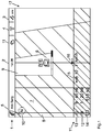
- a configuration menu is provided, such as in Fig. 2 shown.
- the configuration menu is used to arrange the information according to the user's request in the area 11, so that they then in the map view of the Fig. 1 so be displayed.
- the change from the map view or from another surface of the terminal into the configuration menu can be done by means of an in Fig. 1 not shown virtual control element or by means of a physical control on the terminal.
- the configuration menu in Fig. 2 shows in the lower area 11 according to the Fig. 1 the arrangement of different information. These include, the processed area 12, the total area 13, the remaining amount of agricultural good in a container 14 and the current speed of the agricultural machine 15.
- the information available for display is shown. This can be the indication of numerical values, such as instantaneous measured values, for example the speed, or the specification of set parameters, for example a desired quantity of good to be applied. Also can be provided its status information, such as an activated or deactivated automatic mode in the form of a symbol 21 in the area 11 represent.
- the area 11 is subdivided by vertical and horizontal lines 22 into subregions which form a grid for the arrangement of the information to be displayed.
- the arrangement of the information to be displayed can thus take place according to the grid at fixed intervals or at fixed positions.
- the user configures area 11 by interacting with the terminal via the touch-sensitive screen. For example, it may be provided to touch the information to be displayed in area 20 and then to touch the position in area 11 where the corresponding information is to be displayed, whereupon the corresponding information is displayed at the marked position. Alternatively, it can be provided to move the desired information, in this case the surface to be processed, by permanently touching the screen along a path 23 with starting point 24 and end point 25 from region 20 into region 11 to the location at which the information should be displayed. Accordingly, it may be provided to remove information from area 11 by moving the information, in this case the speed, which is no longer to be displayed, out of area 11 by touching along a path 26.
- Points 27 indicate that several, in this case three, pages of information correspond to those in Fig. 1 shown points 17 are configurable.
- the current page to be configured is indicated by an enlarged dot.
- the selection of the pages to be configured is made by a touching sideways swipe gesture on the screen of the terminal. It can also, depending on the requirement, be displayed on several pages at least partially the same information.
- the display of information in area 11 may be configured such that on each of three displayable pages of information in this example, the current speed is displayed.
- Points 28 indicate that there are five pages of information that can be displayed in area 11. Within these pages it is possible to scroll with a sideways swiping gesture and in each case select the information by means of a corresponding touch and move it into the area 11, which in the map view of FIG Fig. 1 to be displayed when processing the agricultural area.
Landscapes
- Life Sciences & Earth Sciences (AREA)
- Engineering & Computer Science (AREA)
- Mechanical Engineering (AREA)
- Soil Sciences (AREA)
- Environmental Sciences (AREA)
- Management, Administration, Business Operations System, And Electronic Commerce (AREA)
- User Interface Of Digital Computer (AREA)
Abstract
das Terminal Informationen (12, 13, 14, 15) über den Bearbeitungsvorgang der landtechnischen Maschine ermittelt und in einem Bereich (11) des Bildschirms, insbesondere in einem Bereich der Kartenansicht, darstellt, wobei die Auswahl und Anordnung der Informationen auf dem Bildschirm in einem Konfigurationsmenü des Terminals konfigurierbar ist.
Description
- Die Erfindung betrifft ein Terminal zur Steuerung einer landtechnischen Maschine gemäß dem Oberbegriff des Patentanspruches 1.
- Die zunehmende Komplexität landtechnischer Maschinen bedingt eine immer größere Detailtiefe von Einstellparametern dieser Maschinen. Um eine Bearbeitung mit der jeweiligen Maschine durchzuführen, muss also eine zunehmend große Anzahl von Parametern für die jeweils verwendete Maschine einstellbar sein und eine entsprechende Fülle von Informationen anzeigbar sein. Für derartige Zwecke hat sich die Verwendung von sogenannten Terminals für die Steuerung von landtechnischen Maschinen durchgesetzt. Diese Terminals ermöglichen es dem Benutzer die gewünschten Parameter der landtechnischen Maschine einzustellen und die jeweils gewünschten Informationen anzuzeigen.
- Derartige Terminals sind typischerweise in der Kabine eines Schleppers, an den die landtechnische Maschine angekoppelt ist, oder einer selbstfahrenden landtechnischen Maschine angeordnet. Aufgrund der Vielzahl von Bedienelementen in der Kabine des Schleppers ist der verfügbare Platz oft stark limitiert, so dass die Größe derartiger Terminals begrenzt ist. Aus diesem Grund verfügen landwirtschaftliche Terminals oftmals über berührungsempfindliche Bildschirme mit integrierten Bedienelementen, so dass die verfügbare Anzeigefläche maximiert werden kann. Teilweise werden in den Terminals auch berührungsempfindliche Bildschirme mit physikalischen Knöpfen und Tastern kombiniert, welche den Vorteil einer haptischen Rückmeldung eines Schaltereignisses bieten.
- Ein derartiges Terminal wird beispielsweise durch die
US2012/0256843A1 offenbart. Dieses Terminal zeigt einen berührungsempfindlichen Bildschirm und verschiedene Bedienelemente. Die Menüoberfläche des Terminal ermöglicht die Einstellung verschiedenster Parameter und die Anzeige von weitreichenden Informationen des Arbeitsprozesses. So können beispielsweise Maschinenparameter angezeigt und ausgelesen werden. Auch ist vorgesehen die Maschine auf der bearbeiteten Fläche in einer Kartenansicht darzustellen. Ebenso können mittels des Terminals Kurzwahltasten eines mit dem Terminal verbundenen Handgriffs mit Funktionen belegt werden. In Vorbereitung des eigentlichen Bearbeitungsvorganges können somit mittels verschiedener Menüs das Terminal selbst, Peripheriegeräte und die zu steuernden Maschinen mittels des Terminals eingestellt und eingerichtet werden. - Während des Bearbeitungsvorganges mit der landtechnischen Maschine auf der landwirtschaftlichen Fläche wird oftmals die Kartenansicht verwendet, um den Bearbeitungsvorgang zu überwachen. Die Kartenansicht ermöglicht es in der Regel die aktuelle Position auf der landwirtschaftlichen Fläche, die bereits bearbeitete und die noch unbearbeitete Fläche sowie die Feldgrenze anzuzeigen. Zudem ist oftmals eine Unterscheidung zwischen aktivierten und nichtaktivierten Teilbreiten der landtechnischen Maschine und eine Anzeige deren Position möglich. Wichtige Statusinformationen, wie die Größe der bereits bearbeiteten Fläche, der Restinhalt eines Vorratstanks oder die aktuelle Geschwindigkeit lassen sich oftmals zusätzlich anzeigen. Die angezeigten Informationen sind hierbei festgelegt. Nachteilig an bekannten Terminals ist somit, dass die in der Kartenansicht darzustellenden Informationen nicht oder nur sehr umständlich konfiguriert werden können.
- Aufgabe der vorliegenden Erfindung ist es, ein landwirtschaftliches Terminal anzugeben, welches eine flexiblere Möglichkeit der Anzeige von Informationen bereitstellt.
- Diese Aufgabe wird durch den kennzeichnenden Teil des Anspruchs 1 gelöst. Demnach ermittelt das Terminal Informationen über den Bearbeitungsvorgang des landwirtschaftlichen Maschinensystems und stellt diese in einem Bereich des Bildschirms, insbesondere im Bereich der Kartenansicht dar, wobei die Auswahl und Anordnung der Informationen auf dem Bildschirm in einem Konfigurationsmenü des Terminals konfigurierbar ist. Erfindungsgemäß ist also vorgesehen, dass die dargestellten Informationen durch den Benutzer konfiguriert werden können, da sich diesbezüglich die Wünsche des jeweiligen Benutzers stark unterscheiden können. Die darzustellenden Informationen können auch von der jeweils verwendeten landtechnischen Maschine abhängen. So ist es beispielsweise unnötig für die Bearbeitung mit einem Pflug die Angabe eines Behälterinhaltes einer Verteilmaschine vorzusehen, da ein Pflug einen solchen Behälter nicht besitzt. Daher ist es von großem Vorteil eine Anzeige bereitzustellen, die mittels einer Konfigurationsmenüs die Möglichkeit für den Benutzer bietet, die Anzeige der Informationen auf den jeweiligen Benutzer und/oder den jeweiligen Bearbeitungsvorgang abzustimmen.
- In einer vorteilhaften Ausgestaltung sind für die Darstellung ein oder mehrere der folgenden Informationen zumindest auswählbar und werden von der landtechnischen Maschine bereitgestellt:
- Geschwindigkeit des landwirtschaftlichen Maschinensystems,
- gesamte zu bearbeitende Fläche
- bereits bearbeitete Fläche
- noch zu bearbeitende Fläche
- Inhalt eines Vorratstanks
- Einstellparameter des landwirtschaftlichen Maschinensystems, wie eingestellte Arbeitsbreite, aktivierte oder deaktivierte Teilbreiten, Arbeitstiefe, Ausbringmenge
- Statusinformationen der landtechnischen Maschine.
- Es kann vorgesehen sein, dass das Terminal die darstellbaren Informationen in Abhängigkeit einer von dem Terminal automatisch erkannten oder durch den Benutzer in das Terminal eingegebenen landtechnischen Maschine auswählt. Es können durch den Benutzer also nur diejenigen Informationen zur Anzeige gebracht werden, die durch die aktuell verwendete landtechnische Maschine auch bereitgestellt werden. Die jeweils verwendete landtechnische Maschine kann beispielsweise durch eine Datenverbindung, insbesondere eine Isobus-Verbindung zwischen dem Terminal und der landtechnischen Maschine ermittelt werden.
- In einer vorteilhaften Weiterbildung der Erfindung ist vorgesehen, mittels einer Bewegungsgeste und/oder Berührungsgeste auf dem berührungsempfindlichen Bildschirm in dem Konfigurationsmenü die anzuzeigende Information auszuwählen und in einen gewünschten Bereich des Bildschirms zu bewegen, in dem die Information angezeigt werden soll. Auf diese Weise können die anzuzeigenden Informationen sehr intuitiv in den Bereich bewegt bzw. gezogen werden, in dem sie auf dem Bildschirm angezeigt werden sollen, so dass die Konfiguration der Anzeige der Informationen sehr zeitsparend und effektiv möglich ist.
- In einer möglichen Ausgestaltung der Erfindung erfolgt die Darstellung der Informationen durch das Terminal zumindest im Bereich der Kartenansicht halbtransparent, so dass sowohl die Informationen, als auch der dahinterliegende Kartenbereich sichtbar sind. Auf diese Weise kann der Bildschirmbereich optimal genutzt werden, da die anzuzeigende Information immer im Vordergrund ablesbar ist, die dahinterliegende Karte jedoch ebenso erkannt werden kann.
- Es kann vorgesehen sein, dass in den dargestellten Informationen durch eine Wischgeste auf dem berührungsempfindlichen Bildschirm des Terminals geblättert werden kann, so dass wahlweise eine von mehreren Anordnungen mit jeweils verschiedenen Informationen in dem Bereich dargestellt wird. Auf diese Weise kann eine Vielzahl von Informationen sehr schnell und effektiv zugänglich gemacht werden. Eine Wischgeste ermöglicht es dem Benutzer von einer ersten Anordnung von Informationen in eine zweite Anordnung oder weitere Anordnungen zu wechseln und so in der jeweiligen Situation die benötigten Informationen schnell angezeigt zu bekommen. Auch ist es denkbar die verschiedenen Anordnungen für verschiedene Benutzer und/oder landtechnische Maschinen zu konfigurieren, so dass für den jeweiligen Benutzer oder die jeweils verwendete landtechnische Maschine mittels der Wischgeste lediglich die gewünschte Anordnung von Informationen ausgewählt werden muss, was eine sehr effektive Art der Terminalbenutzung und Anzeige von Informationen darstellt, da nicht jeweils erneut die Informationsanzeige neu konfiguriert werden muss.
- Weitere vorteilhafte Ausgestaltungen ergeben sich aus der Beispielsbeschreibung. Hierbei zeigen
- Fig. 1
- eine erfindungsgemäße Darstellung von Informationen in der Kartenansicht eines erfindungsgemäßen Terminals und
- Fig. 2
- ein Konfigurationsmenü eines erfindungsgemäßen Terminals.
- Eine erfindungsgemäße Darstellung von Informationen ist in
Fig. 1 gezeigt. Dargestellt ist die Bildschirmansicht eines erfindungsgemäßen Terminals. Dieses zeigt im oberen Bereich 1 mehrere Symbole zur Anzeige verschiedener Informationen in einer Statusleiste. Diese kann beispielsweise die Angabe einer Uhrzeit 2, der Qualität eines GPS-Signals 3, die Qualität einer drahtlosen Datenverbindung 4, die derzeitige Position auf einer bekannten landwirtschaftlichen Fläche 5 oder Angaben zur aktuellen Wetterlage 11 umfassen. - Zudem ist eine landtechnische Maschine 6 gezeigt, die eine landwirtschaftliche Fläche 7 bearbeitet, wobei die bearbeitete Fläche 8 farblich oder mittels eines Schraffur abweichend von der unbearbeiteten Fläche 9 dargestellt sein kann. Verschiedene Informationen können im Bereich der landwirtschaftlichen Fläche dargestellt werden, wie die aktuelle Lage der Himmelsrichtung Norden relativ zur landtechnischen Maschine 10. Zudem ist im unteren Bereich 11 der Kartenansicht eine erfindungsgemäße Miniaturansicht vorhanden, welche Auskunft gibt über die bearbeitete Fläche 12, die Gesamtfläche 13, die Restmenge 14 an landwirtschaftlichem Gut in einem Behälter und die aktuelle Geschwindigkeit 15 der landtechnischen Maschine. Die Darstellung weiterer Informationen ist denkbar. Die Punkte 16 zeigen an, dass weitere Informationen in der Miniaturansicht dargestellt werden können, welche durch eine berührende, horizontale Wischgeste auf dem Bildschirm des Terminals jeweils wahlweise angezeigt oder ausgeblendet werden können. Es kann hiermit durch mehrere Anordnungen von Informationen geblättert werden. Es kann vorgesehen sein, auf der rechten Seite 17 verschiedene virtuelle Bedienelemente beispielsweise durch eine nicht dargestellte physikalische Taste am Gehäuse des Terminals, einzublenden. Die Miniaturansicht 11 besitzt eine durch eine Schraffur angedeutete Transparenz, so dass der dahinterliegende Teil der Kartenansicht ebenfalls erkannt werden kann.
- Erfindungsgemäß ist ein Konfigurationsmenü vorgesehen, wie beispielsweise in
Fig. 2 dargestellt. Das Konfigurationsmenü dient dazu, die Informationen nach dem Wunsch des Benutzers im Bereich 11 anzuordnen, so dass diese dann in der Kartenansicht derFig. 1 so zur Anzeige gebracht werden. Der Wechsel aus der Kartenansicht oder aus einer anderen Oberfläche des Terminals in das Konfigurationsmenü kann mittels eines inFig. 1 nicht dargestellten virtuellen Bedienelementes oder mittels eines physikalischen Bedienelementes am Terminal erfolgen. - Das Konfigurationsmenü in
Fig. 2 zeigt im unteren Bereich 11 entsprechend derFig. 1 die Anordnung von verschiedenen Informationen. Hierzu gehören, die bearbeitete Fläche 12, die Gesamtfläche 13, die Restmenge an landwirtschaftlichem Gut in einem Behälter 14 und die aktuelle Geschwindigkeit der landtechnischen Maschine 15. Im Bereich 20 sind die zur Darstellung verfügbaren Informationen abgebildet. Hierbei kann es sich um die Angabe von Zahlenwerten handeln, wie momentane Messwerte, beispielsweise die Geschwindigkeit, oder um die Angabe von eingestellten Parametern, beispielsweise eine auszubringende Sollmenge an Gut. Auch kann vorgesehen sein Statusinformationen, wie beispielsweise einen aktivierten oder deaktivierten Automatikmodus in Form eines Symbols 21 in dem Bereich 11 darzustellen. - Der Bereich 11 ist durch vertikale und horizontale Linien 22 in Unterbereiche unterteilt, welche ein Raster für die Anordnung der darzustellenden Informationen bilden. Die Anordnung der darzustellenden Informationen kann also gemäß des Rasters in festgelegten Abständen bzw. an festgelegten Positionen erfolgen.
- Die Konfiguration des Bereichs 11 durch den Benutzer erfolgt durch Interaktion mit dem Terminal mittels des berührungsempfindlichen Bildschirms. Beispielsweise kann vorgesehen sein, die anzuzeigende Information im Bereich 20 zu berühren und anschließend die Position in dem Bereich 11 zu berühren, an dem die entsprechende Information angezeigt werden soll, woraufhin die entsprechende Information an der markierten Position angezeigt wird. Alternativ kann vorgesehen sein, die gewünschte Information, in diesem Fall die zu bearbeitende Fläche, durch permanente Berührung des Bildschirmes entlang eines Pfades 23 mit Startpunkt 24 und Endpunkt 25 aus dem Bereich 20 in den Bereich 11 an den Ort zu bewegen, an dem die Information angezeigt werden soll. Entsprechend kann vorgesehen sein, Informationen aus dem Bereich 11 zu entfernen, indem die nicht mehr darzustellende Information, in diesem Fall die Geschwindigkeit, durch Berühren entlang eines Pfades 26 aus dem Bereich 11 herausbewegt wird.
- Die Punkte 27 zeigen an, dass mehrere, in diesem Fall drei, Seiten von Informationen entsprechend der in
Fig. 1 gezeigten Punkte 17 konfigurierbar sind. Die jeweils derzeit zu konfigurierende Seite wird durch einen vergrößerten Punkt angezeigt. Die Auswahl der zu konfigurierenden Seiten erfolgt durch eine berührende seitwärts gerichtete Wischgeste auf dem Bildschirm des Terminals. Es kann auch, je nach Erfordernis, auf mehreren Seiten zumindest teilweise dieselbe Information anzeigbar sein. So kann die Anzeige von Informationen im Bereich 11 beispielsweise derart konfiguriert sein, dass auf jeder der in diesem Beispiel drei darstellbaren Seiten mit Informationen die derzeitige Geschwindigkeit angezeigt wird. - Die Punkte 28 zeigen an, dass fünf Seiten mit im Bereich 11 darstellbaren Informationen zur Auswahl stehen. Innerhalb dieser Seiten kann mit einer seitwärts gerichteten Wischgeste geblättert werden und jeweils die Informationen mittels einer entsprechenden Berührung ausgewählt und in den Bereich 11 bewegt werden, die in der Kartenansicht der
Fig. 1 bei der Bearbeitung der landwirtschaftlichen Fläche angezeigt werden sollen. - Es kann vorgesehen sein im Hintergrund der Konfigurationsmenüs die Kartenansicht einzublenden, was in
Fig. 2 durch die Darstellung des Kompass im oberen linken Bereich entsprechend derFig. 1 angedeutet ist.
Claims (5)
- Terminal zur Steuerung einer landtechnischen Maschine, wobei das Terminal über einen berührungsempfindlichen Bildschirm verfügt, wobei das Terminal mit einem Positionserfassungssystem verbunden und ausgebildet ist, die aktuelle Position der landtechnischen Maschine in einer Kartenansicht auf einer landwirtschaftlichen Fläche anzuzeigen,
dadurch gekennzeichnet, dass,
das Terminal Informationen (12, 13, 14, 15) über den Bearbeitungsvorgang der landtechnischen Maschine ermittelt und in einem Bereich (11) des Bildschirms, insbesondere in einem Bereich der Kartenansicht, darstellt, wobei die Auswahl und Anordnung der Informationen auf dem Bildschirm in einem Konfigurationsmenü des Terminals konfigurierbar ist. - Terminal nach Anspruch 1, dadurch gekennzeichnet, dass für die Darstellung ein oder mehrere der folgenden Informationen zumindest auswählbar sind und von der landtechnischen Maschine bereitgestellt werden:- Geschwindigkeit der landtechnischen Maschine (15),- gesamte zu bearbeitende Fläche (13)- bereits bearbeitete Fläche (12)- noch zu bearbeitende Fläche- Inhalt eines Vorratstanks (14)- Einstellparameter der landtechnischen Maschine, wie eingestellte Arbeitsbreite, aktivierte oder deaktivierte Teilbreiten, Arbeitstiefe, Ausbringmenge.
- Terminal nach Anspruch 1 oder 2, dadurch kennzeichnet, dass mittels einer Bewegungsgeste und/oder Berührungsgeste (23, 26) auf dem berührungsempfindlichen Bildschirm in dem Konfigurationsmenü die anzuzeigende Information ausgewählt und in einen gewünschten Bereich (11) des Bildschirms bewegt werden kann, in dem die Information angezeigt werden soll.
- Terminal nach zumindest einem der vorhergehenden Ansprüche, dadurch gekennzeichnet, dass die Darstellung der Informationen durch das Terminal zumindest im Bereich (11) der Kartenansicht halbtransparent erfolgt, so dass sowohl die Informationen (12, 13, 14, 15), als auch der dahinterliegende Kartenbereich sichtbar sind.
- Terminal nach zumindest einem der vorhergehenden Ansprüche, dadurch gekennzeichnet, dass in den dargestellten Informationen (12, 13, 14, 15) durch eine Wischgeste auf dem berührungsempfindlichen Bildschirm des Terminals geblättert werden kann, so dass wahlweise eine von mehreren Anordnungen mit jeweils verschiedenen Informationen (12, 13, 14, 15) in dem Bereich dargestellt wird.
Applications Claiming Priority (1)
| Application Number | Priority Date | Filing Date | Title |
|---|---|---|---|
| DE102017105490.1A DE102017105490A1 (de) | 2017-03-15 | 2017-03-15 | Landwirtschaftliches Terminal |
Publications (2)
| Publication Number | Publication Date |
|---|---|
| EP3378299A1 true EP3378299A1 (de) | 2018-09-26 |
| EP3378299B1 EP3378299B1 (de) | 2020-05-13 |
Family
ID=61837700
Family Applications (1)
| Application Number | Title | Priority Date | Filing Date |
|---|---|---|---|
| EP18401027.0A Active EP3378299B1 (de) | 2017-03-15 | 2018-03-12 | Landwirtschaftliches terminal |
Country Status (3)
| Country | Link |
|---|---|
| EP (1) | EP3378299B1 (de) |
| DE (1) | DE102017105490A1 (de) |
| DK (1) | DK3378299T3 (de) |
Cited By (33)
| Publication number | Priority date | Publication date | Assignee | Title |
|---|---|---|---|---|
| US11079725B2 (en) | 2019-04-10 | 2021-08-03 | Deere & Company | Machine control using real-time model |
| US11178818B2 (en) | 2018-10-26 | 2021-11-23 | Deere & Company | Harvesting machine control system with fill level processing based on yield data |
| US11234366B2 (en) | 2019-04-10 | 2022-02-01 | Deere & Company | Image selection for machine control |
| US11240961B2 (en) | 2018-10-26 | 2022-02-08 | Deere & Company | Controlling a harvesting machine based on a geo-spatial representation indicating where the harvesting machine is likely to reach capacity |
| US20220110251A1 (en) | 2020-10-09 | 2022-04-14 | Deere & Company | Crop moisture map generation and control system |
| US11467605B2 (en) | 2019-04-10 | 2022-10-11 | Deere & Company | Zonal machine control |
| US11474523B2 (en) | 2020-10-09 | 2022-10-18 | Deere & Company | Machine control using a predictive speed map |
| US11477940B2 (en) | 2020-03-26 | 2022-10-25 | Deere & Company | Mobile work machine control based on zone parameter modification |
| US11592822B2 (en) | 2020-10-09 | 2023-02-28 | Deere & Company | Machine control using a predictive map |
| US11589509B2 (en) | 2018-10-26 | 2023-02-28 | Deere & Company | Predictive machine characteristic map generation and control system |
| US11635765B2 (en) | 2020-10-09 | 2023-04-25 | Deere & Company | Crop state map generation and control system |
| US11641800B2 (en) | 2020-02-06 | 2023-05-09 | Deere & Company | Agricultural harvesting machine with pre-emergence weed detection and mitigation system |
| US11650587B2 (en) | 2020-10-09 | 2023-05-16 | Deere & Company | Predictive power map generation and control system |
| US11653588B2 (en) | 2018-10-26 | 2023-05-23 | Deere & Company | Yield map generation and control system |
| US11672203B2 (en) | 2018-10-26 | 2023-06-13 | Deere & Company | Predictive map generation and control |
| US11675354B2 (en) | 2020-10-09 | 2023-06-13 | Deere & Company | Machine control using a predictive map |
| US11711995B2 (en) | 2020-10-09 | 2023-08-01 | Deere & Company | Machine control using a predictive map |
| US11727680B2 (en) | 2020-10-09 | 2023-08-15 | Deere & Company | Predictive map generation based on seeding characteristics and control |
| US11778945B2 (en) | 2019-04-10 | 2023-10-10 | Deere & Company | Machine control using real-time model |
| US11825768B2 (en) | 2020-10-09 | 2023-11-28 | Deere & Company | Machine control using a predictive map |
| US11844311B2 (en) | 2020-10-09 | 2023-12-19 | Deere & Company | Machine control using a predictive map |
| US11845449B2 (en) | 2020-10-09 | 2023-12-19 | Deere & Company | Map generation and control system |
| US11849672B2 (en) | 2020-10-09 | 2023-12-26 | Deere & Company | Machine control using a predictive map |
| US11849671B2 (en) | 2020-10-09 | 2023-12-26 | Deere & Company | Crop state map generation and control system |
| US11864483B2 (en) | 2020-10-09 | 2024-01-09 | Deere & Company | Predictive map generation and control system |
| US11874669B2 (en) | 2020-10-09 | 2024-01-16 | Deere & Company | Map generation and control system |
| US11889787B2 (en) | 2020-10-09 | 2024-02-06 | Deere & Company | Predictive speed map generation and control system |
| US11889788B2 (en) | 2020-10-09 | 2024-02-06 | Deere & Company | Predictive biomass map generation and control |
| US11895948B2 (en) | 2020-10-09 | 2024-02-13 | Deere & Company | Predictive map generation and control based on soil properties |
| US11927459B2 (en) | 2020-10-09 | 2024-03-12 | Deere & Company | Machine control using a predictive map |
| US11946747B2 (en) | 2020-10-09 | 2024-04-02 | Deere & Company | Crop constituent map generation and control system |
| US11957072B2 (en) | 2020-02-06 | 2024-04-16 | Deere & Company | Pre-emergence weed detection and mitigation system |
| US11983009B2 (en) | 2020-10-09 | 2024-05-14 | Deere & Company | Map generation and control system |
Families Citing this family (1)
| Publication number | Priority date | Publication date | Assignee | Title |
|---|---|---|---|---|
| CN115152410B (zh) * | 2022-08-15 | 2023-05-09 | 四川农业大学 | 一种多功能组合式玉米实时测产装置及方法 |
Citations (4)
| Publication number | Priority date | Publication date | Assignee | Title |
|---|---|---|---|---|
| US5751576A (en) * | 1995-12-18 | 1998-05-12 | Ag-Chem Equipment Co., Inc. | Animated map display method for computer-controlled agricultural product application equipment |
| US20120256843A1 (en) * | 2009-09-16 | 2012-10-11 | Agco Gmbh | Control unit for display terminal |
| EP2583544A1 (de) * | 2011-10-20 | 2013-04-24 | CLAAS Agrosystems KGaA mbH & Co KG. | Visualisierungseinrichtung |
| JP2016093126A (ja) * | 2014-11-13 | 2016-05-26 | ヤンマー株式会社 | 操作端末 |
-
2017
- 2017-03-15 DE DE102017105490.1A patent/DE102017105490A1/de not_active Withdrawn
-
2018
- 2018-03-12 DK DK18401027.0T patent/DK3378299T3/da active
- 2018-03-12 EP EP18401027.0A patent/EP3378299B1/de active Active
Patent Citations (4)
| Publication number | Priority date | Publication date | Assignee | Title |
|---|---|---|---|---|
| US5751576A (en) * | 1995-12-18 | 1998-05-12 | Ag-Chem Equipment Co., Inc. | Animated map display method for computer-controlled agricultural product application equipment |
| US20120256843A1 (en) * | 2009-09-16 | 2012-10-11 | Agco Gmbh | Control unit for display terminal |
| EP2583544A1 (de) * | 2011-10-20 | 2013-04-24 | CLAAS Agrosystems KGaA mbH & Co KG. | Visualisierungseinrichtung |
| JP2016093126A (ja) * | 2014-11-13 | 2016-05-26 | ヤンマー株式会社 | 操作端末 |
Cited By (36)
| Publication number | Priority date | Publication date | Assignee | Title |
|---|---|---|---|---|
| US11589509B2 (en) | 2018-10-26 | 2023-02-28 | Deere & Company | Predictive machine characteristic map generation and control system |
| US11178818B2 (en) | 2018-10-26 | 2021-11-23 | Deere & Company | Harvesting machine control system with fill level processing based on yield data |
| US11672203B2 (en) | 2018-10-26 | 2023-06-13 | Deere & Company | Predictive map generation and control |
| US11240961B2 (en) | 2018-10-26 | 2022-02-08 | Deere & Company | Controlling a harvesting machine based on a geo-spatial representation indicating where the harvesting machine is likely to reach capacity |
| US11653588B2 (en) | 2018-10-26 | 2023-05-23 | Deere & Company | Yield map generation and control system |
| US11778945B2 (en) | 2019-04-10 | 2023-10-10 | Deere & Company | Machine control using real-time model |
| US11467605B2 (en) | 2019-04-10 | 2022-10-11 | Deere & Company | Zonal machine control |
| US11829112B2 (en) | 2019-04-10 | 2023-11-28 | Deere & Company | Machine control using real-time model |
| US11079725B2 (en) | 2019-04-10 | 2021-08-03 | Deere & Company | Machine control using real-time model |
| US11234366B2 (en) | 2019-04-10 | 2022-02-01 | Deere & Company | Image selection for machine control |
| US11650553B2 (en) | 2019-04-10 | 2023-05-16 | Deere & Company | Machine control using real-time model |
| US11957072B2 (en) | 2020-02-06 | 2024-04-16 | Deere & Company | Pre-emergence weed detection and mitigation system |
| US11641800B2 (en) | 2020-02-06 | 2023-05-09 | Deere & Company | Agricultural harvesting machine with pre-emergence weed detection and mitigation system |
| US11477940B2 (en) | 2020-03-26 | 2022-10-25 | Deere & Company | Mobile work machine control based on zone parameter modification |
| US11727680B2 (en) | 2020-10-09 | 2023-08-15 | Deere & Company | Predictive map generation based on seeding characteristics and control |
| US11849671B2 (en) | 2020-10-09 | 2023-12-26 | Deere & Company | Crop state map generation and control system |
| US11675354B2 (en) | 2020-10-09 | 2023-06-13 | Deere & Company | Machine control using a predictive map |
| US11711995B2 (en) | 2020-10-09 | 2023-08-01 | Deere & Company | Machine control using a predictive map |
| US11635765B2 (en) | 2020-10-09 | 2023-04-25 | Deere & Company | Crop state map generation and control system |
| US11592822B2 (en) | 2020-10-09 | 2023-02-28 | Deere & Company | Machine control using a predictive map |
| US11474523B2 (en) | 2020-10-09 | 2022-10-18 | Deere & Company | Machine control using a predictive speed map |
| US11825768B2 (en) | 2020-10-09 | 2023-11-28 | Deere & Company | Machine control using a predictive map |
| US11844311B2 (en) | 2020-10-09 | 2023-12-19 | Deere & Company | Machine control using a predictive map |
| US11845449B2 (en) | 2020-10-09 | 2023-12-19 | Deere & Company | Map generation and control system |
| US11849672B2 (en) | 2020-10-09 | 2023-12-26 | Deere & Company | Machine control using a predictive map |
| US11650587B2 (en) | 2020-10-09 | 2023-05-16 | Deere & Company | Predictive power map generation and control system |
| US11864483B2 (en) | 2020-10-09 | 2024-01-09 | Deere & Company | Predictive map generation and control system |
| US11871697B2 (en) | 2020-10-09 | 2024-01-16 | Deere & Company | Crop moisture map generation and control system |
| US11874669B2 (en) | 2020-10-09 | 2024-01-16 | Deere & Company | Map generation and control system |
| US11889787B2 (en) | 2020-10-09 | 2024-02-06 | Deere & Company | Predictive speed map generation and control system |
| US11889788B2 (en) | 2020-10-09 | 2024-02-06 | Deere & Company | Predictive biomass map generation and control |
| US11895948B2 (en) | 2020-10-09 | 2024-02-13 | Deere & Company | Predictive map generation and control based on soil properties |
| US11927459B2 (en) | 2020-10-09 | 2024-03-12 | Deere & Company | Machine control using a predictive map |
| US11946747B2 (en) | 2020-10-09 | 2024-04-02 | Deere & Company | Crop constituent map generation and control system |
| US20220110251A1 (en) | 2020-10-09 | 2022-04-14 | Deere & Company | Crop moisture map generation and control system |
| US11983009B2 (en) | 2020-10-09 | 2024-05-14 | Deere & Company | Map generation and control system |
Also Published As
| Publication number | Publication date |
|---|---|
| EP3378299B1 (de) | 2020-05-13 |
| DE102017105490A1 (de) | 2018-09-20 |
| DK3378299T3 (da) | 2020-08-10 |
Similar Documents
| Publication | Publication Date | Title |
|---|---|---|
| EP3378299B1 (de) | Landwirtschaftliches terminal | |
| EP3378298A1 (de) | Landwirtschaftliches terminal | |
| DE102012219119B4 (de) | Intelligente Fenstererstellung in einer grafischen Benutzeroberfläche | |
| AT512737B1 (de) | Schweißgerät | |
| DE102012107551A1 (de) | Anzeigevorrichtung für Landmaschinen | |
| EP1374027B1 (de) | Positionieren von auf einer benutzeroberfläche angezeigten bereichen | |
| EP2930051B1 (de) | Vorrichtung und Verfahren zum Bereitstellen einer graphischen Benutzerschnittstelle in einem Fahrzeug | |
| DE102010042326A1 (de) | Anzeigesteuervorrichtung für eine Fernsteuerungsvorrichtung | |
| EP2698701A2 (de) | Anzeigenvorrichtung für Landmaschinen | |
| EP2930603A1 (de) | Verfahren und Vorrichtung zum Bereitstellen einer graphischen Benutzerschnittstelle in einem Fahrzeug | |
| DE102013203526A1 (de) | Verfahren und System für die Verwendung von Einstellungs-Handles zur Erleichterung der dynamischen Layout-Editierung | |
| DE102013015024A1 (de) | Verzahnmaschine | |
| DE102019106285A1 (de) | Verfahren zum automatischen Ausrichten eines Fensters innerhalb einer Benutzeroberfläche | |
| DE102016006762A1 (de) | Informationsverarbeitungsvorrichtung zum editieren elektronischer daten durch berührung | |
| EP3333292B1 (de) | Verfahren und hilfsanordnung zum einstellen einer kettenwirkmaschine | |
| EP0858016B1 (de) | Numerische Steuerung mit Bedienoberfläche in Fenstertechnik | |
| EP3165976B1 (de) | Bedienvorrichtung und -verfahren für spinnereivorbereitungsmaschinen | |
| EP3224748B1 (de) | Computerbasiertes entwurfssystem für ein elektrisches antriebssystem | |
| EP2912932B2 (de) | Steuereinheit | |
| WO2010015303A1 (de) | Verfahren zur vergrösserung eines darstellungsbereichs auf einer darstellungseinrichtung | |
| DE102017105494A1 (de) | Landwirtschaftliches Terminal | |
| DE102017105492A1 (de) | Landwirtschaftliches Terminal | |
| EP3542235B1 (de) | Interaktives steuern einer maschine mit rückmeldung eines stellparameters | |
| EP3594166B1 (de) | Kransteuerung mit visualisierungsvorrichtung | |
| EP3378296B1 (de) | Landwirtschaftliches terminal |
Legal Events
| Date | Code | Title | Description |
|---|---|---|---|
| PUAI | Public reference made under article 153(3) epc to a published international application that has entered the european phase |
Free format text: ORIGINAL CODE: 0009012 |
|
| STAA | Information on the status of an ep patent application or granted ep patent |
Free format text: STATUS: THE APPLICATION HAS BEEN PUBLISHED |
|
| AK | Designated contracting states |
Kind code of ref document: A1 Designated state(s): AL AT BE BG CH CY CZ DE DK EE ES FI FR GB GR HR HU IE IS IT LI LT LU LV MC MK MT NL NO PL PT RO RS SE SI SK SM TR |
|
| AX | Request for extension of the european patent |
Extension state: BA ME |
|
| STAA | Information on the status of an ep patent application or granted ep patent |
Free format text: STATUS: REQUEST FOR EXAMINATION WAS MADE |
|
| 17P | Request for examination filed |
Effective date: 20190325 |
|
| RBV | Designated contracting states (corrected) |
Designated state(s): AL AT BE BG CH CY CZ DE DK EE ES FI FR GB GR HR HU IE IS IT LI LT LU LV MC MK MT NL NO PL PT RO RS SE SI SK SM TR |
|
| RIC1 | Information provided on ipc code assigned before grant |
Ipc: A01D 41/127 20060101ALI20191210BHEP Ipc: A01B 69/00 20060101AFI20191210BHEP Ipc: A01B 79/00 20060101ALI20191210BHEP |
|
| GRAP | Despatch of communication of intention to grant a patent |
Free format text: ORIGINAL CODE: EPIDOSNIGR1 |
|
| STAA | Information on the status of an ep patent application or granted ep patent |
Free format text: STATUS: GRANT OF PATENT IS INTENDED |
|
| INTG | Intention to grant announced |
Effective date: 20200117 |
|
| GRAS | Grant fee paid |
Free format text: ORIGINAL CODE: EPIDOSNIGR3 |
|
| GRAA | (expected) grant |
Free format text: ORIGINAL CODE: 0009210 |
|
| STAA | Information on the status of an ep patent application or granted ep patent |
Free format text: STATUS: THE PATENT HAS BEEN GRANTED |
|
| AK | Designated contracting states |
Kind code of ref document: B1 Designated state(s): AL AT BE BG CH CY CZ DE DK EE ES FI FR GB GR HR HU IE IS IT LI LT LU LV MC MK MT NL NO PL PT RO RS SE SI SK SM TR |
|
| REG | Reference to a national code |
Ref country code: GB Ref legal event code: FG4D Free format text: NOT ENGLISH |
|
| REG | Reference to a national code |
Ref country code: CH Ref legal event code: EP |
|
| REG | Reference to a national code |
Ref country code: DE Ref legal event code: R096 Ref document number: 502018001441 Country of ref document: DE |
|
| REG | Reference to a national code |
Ref country code: AT Ref legal event code: REF Ref document number: 1268975 Country of ref document: AT Kind code of ref document: T Effective date: 20200615 |
|
| REG | Reference to a national code |
Ref country code: DK Ref legal event code: T3 Effective date: 20200807 |
|
| REG | Reference to a national code |
Ref country code: NL Ref legal event code: FP |
|
| REG | Reference to a national code |
Ref country code: LT Ref legal event code: MG4D |
|
| PG25 | Lapsed in a contracting state [announced via postgrant information from national office to epo] |
Ref country code: GR Free format text: LAPSE BECAUSE OF FAILURE TO SUBMIT A TRANSLATION OF THE DESCRIPTION OR TO PAY THE FEE WITHIN THE PRESCRIBED TIME-LIMIT Effective date: 20200814 Ref country code: NO Free format text: LAPSE BECAUSE OF FAILURE TO SUBMIT A TRANSLATION OF THE DESCRIPTION OR TO PAY THE FEE WITHIN THE PRESCRIBED TIME-LIMIT Effective date: 20200813 Ref country code: LT Free format text: LAPSE BECAUSE OF FAILURE TO SUBMIT A TRANSLATION OF THE DESCRIPTION OR TO PAY THE FEE WITHIN THE PRESCRIBED TIME-LIMIT Effective date: 20200513 Ref country code: FI Free format text: LAPSE BECAUSE OF FAILURE TO SUBMIT A TRANSLATION OF THE DESCRIPTION OR TO PAY THE FEE WITHIN THE PRESCRIBED TIME-LIMIT Effective date: 20200513 Ref country code: IS Free format text: LAPSE BECAUSE OF FAILURE TO SUBMIT A TRANSLATION OF THE DESCRIPTION OR TO PAY THE FEE WITHIN THE PRESCRIBED TIME-LIMIT Effective date: 20200913 Ref country code: SE Free format text: LAPSE BECAUSE OF FAILURE TO SUBMIT A TRANSLATION OF THE DESCRIPTION OR TO PAY THE FEE WITHIN THE PRESCRIBED TIME-LIMIT Effective date: 20200513 Ref country code: PT Free format text: LAPSE BECAUSE OF FAILURE TO SUBMIT A TRANSLATION OF THE DESCRIPTION OR TO PAY THE FEE WITHIN THE PRESCRIBED TIME-LIMIT Effective date: 20200914 |
|
| PG25 | Lapsed in a contracting state [announced via postgrant information from national office to epo] |
Ref country code: RS Free format text: LAPSE BECAUSE OF FAILURE TO SUBMIT A TRANSLATION OF THE DESCRIPTION OR TO PAY THE FEE WITHIN THE PRESCRIBED TIME-LIMIT Effective date: 20200513 Ref country code: LV Free format text: LAPSE BECAUSE OF FAILURE TO SUBMIT A TRANSLATION OF THE DESCRIPTION OR TO PAY THE FEE WITHIN THE PRESCRIBED TIME-LIMIT Effective date: 20200513 Ref country code: HR Free format text: LAPSE BECAUSE OF FAILURE TO SUBMIT A TRANSLATION OF THE DESCRIPTION OR TO PAY THE FEE WITHIN THE PRESCRIBED TIME-LIMIT Effective date: 20200513 Ref country code: BG Free format text: LAPSE BECAUSE OF FAILURE TO SUBMIT A TRANSLATION OF THE DESCRIPTION OR TO PAY THE FEE WITHIN THE PRESCRIBED TIME-LIMIT Effective date: 20200813 |
|
| PG25 | Lapsed in a contracting state [announced via postgrant information from national office to epo] |
Ref country code: AL Free format text: LAPSE BECAUSE OF FAILURE TO SUBMIT A TRANSLATION OF THE DESCRIPTION OR TO PAY THE FEE WITHIN THE PRESCRIBED TIME-LIMIT Effective date: 20200513 |
|
| PG25 | Lapsed in a contracting state [announced via postgrant information from national office to epo] |
Ref country code: ES Free format text: LAPSE BECAUSE OF FAILURE TO SUBMIT A TRANSLATION OF THE DESCRIPTION OR TO PAY THE FEE WITHIN THE PRESCRIBED TIME-LIMIT Effective date: 20200513 Ref country code: SM Free format text: LAPSE BECAUSE OF FAILURE TO SUBMIT A TRANSLATION OF THE DESCRIPTION OR TO PAY THE FEE WITHIN THE PRESCRIBED TIME-LIMIT Effective date: 20200513 Ref country code: CZ Free format text: LAPSE BECAUSE OF FAILURE TO SUBMIT A TRANSLATION OF THE DESCRIPTION OR TO PAY THE FEE WITHIN THE PRESCRIBED TIME-LIMIT Effective date: 20200513 Ref country code: RO Free format text: LAPSE BECAUSE OF FAILURE TO SUBMIT A TRANSLATION OF THE DESCRIPTION OR TO PAY THE FEE WITHIN THE PRESCRIBED TIME-LIMIT Effective date: 20200513 Ref country code: IT Free format text: LAPSE BECAUSE OF FAILURE TO SUBMIT A TRANSLATION OF THE DESCRIPTION OR TO PAY THE FEE WITHIN THE PRESCRIBED TIME-LIMIT Effective date: 20200513 Ref country code: EE Free format text: LAPSE BECAUSE OF FAILURE TO SUBMIT A TRANSLATION OF THE DESCRIPTION OR TO PAY THE FEE WITHIN THE PRESCRIBED TIME-LIMIT Effective date: 20200513 |
|
| REG | Reference to a national code |
Ref country code: DE Ref legal event code: R097 Ref document number: 502018001441 Country of ref document: DE |
|
| PG25 | Lapsed in a contracting state [announced via postgrant information from national office to epo] |
Ref country code: PL Free format text: LAPSE BECAUSE OF FAILURE TO SUBMIT A TRANSLATION OF THE DESCRIPTION OR TO PAY THE FEE WITHIN THE PRESCRIBED TIME-LIMIT Effective date: 20200513 Ref country code: SK Free format text: LAPSE BECAUSE OF FAILURE TO SUBMIT A TRANSLATION OF THE DESCRIPTION OR TO PAY THE FEE WITHIN THE PRESCRIBED TIME-LIMIT Effective date: 20200513 |
|
| PLBE | No opposition filed within time limit |
Free format text: ORIGINAL CODE: 0009261 |
|
| STAA | Information on the status of an ep patent application or granted ep patent |
Free format text: STATUS: NO OPPOSITION FILED WITHIN TIME LIMIT |
|
| 26N | No opposition filed |
Effective date: 20210216 |
|
| REG | Reference to a national code |
Ref country code: DE Ref legal event code: R081 Ref document number: 502018001441 Country of ref document: DE Owner name: AMAZONEN-WERKE H. DREYER SE & CO. KG, DE Free format text: FORMER OWNER: AMAZONEN-WERKE H. DREYER GMBH & CO. KG, 49205 HASBERGEN, DE |
|
| PG25 | Lapsed in a contracting state [announced via postgrant information from national office to epo] |
Ref country code: SI Free format text: LAPSE BECAUSE OF FAILURE TO SUBMIT A TRANSLATION OF THE DESCRIPTION OR TO PAY THE FEE WITHIN THE PRESCRIBED TIME-LIMIT Effective date: 20200513 |
|
| PG25 | Lapsed in a contracting state [announced via postgrant information from national office to epo] |
Ref country code: MC Free format text: LAPSE BECAUSE OF FAILURE TO SUBMIT A TRANSLATION OF THE DESCRIPTION OR TO PAY THE FEE WITHIN THE PRESCRIBED TIME-LIMIT Effective date: 20200513 |
|
| REG | Reference to a national code |
Ref country code: CH Ref legal event code: PL |
|
| REG | Reference to a national code |
Ref country code: BE Ref legal event code: MM Effective date: 20210331 |
|
| PG25 | Lapsed in a contracting state [announced via postgrant information from national office to epo] |
Ref country code: CH Free format text: LAPSE BECAUSE OF NON-PAYMENT OF DUE FEES Effective date: 20210331 Ref country code: IE Free format text: LAPSE BECAUSE OF NON-PAYMENT OF DUE FEES Effective date: 20210312 Ref country code: LU Free format text: LAPSE BECAUSE OF NON-PAYMENT OF DUE FEES Effective date: 20210312 Ref country code: LI Free format text: LAPSE BECAUSE OF NON-PAYMENT OF DUE FEES Effective date: 20210331 |
|
| PG25 | Lapsed in a contracting state [announced via postgrant information from national office to epo] |
Ref country code: BE Free format text: LAPSE BECAUSE OF NON-PAYMENT OF DUE FEES Effective date: 20210331 |
|
| GBPC | Gb: european patent ceased through non-payment of renewal fee |
Effective date: 20220312 |
|
| PG25 | Lapsed in a contracting state [announced via postgrant information from national office to epo] |
Ref country code: GB Free format text: LAPSE BECAUSE OF NON-PAYMENT OF DUE FEES Effective date: 20220312 |
|
| PGFP | Annual fee paid to national office [announced via postgrant information from national office to epo] |
Ref country code: FR Payment date: 20230110 Year of fee payment: 6 Ref country code: DK Payment date: 20230314 Year of fee payment: 6 |
|
| P01 | Opt-out of the competence of the unified patent court (upc) registered |
Effective date: 20230523 |
|
| PG25 | Lapsed in a contracting state [announced via postgrant information from national office to epo] |
Ref country code: CY Free format text: LAPSE BECAUSE OF FAILURE TO SUBMIT A TRANSLATION OF THE DESCRIPTION OR TO PAY THE FEE WITHIN THE PRESCRIBED TIME-LIMIT Effective date: 20200513 |
|
| PG25 | Lapsed in a contracting state [announced via postgrant information from national office to epo] |
Ref country code: HU Free format text: LAPSE BECAUSE OF FAILURE TO SUBMIT A TRANSLATION OF THE DESCRIPTION OR TO PAY THE FEE WITHIN THE PRESCRIBED TIME-LIMIT; INVALID AB INITIO Effective date: 20180312 |
|
| PGFP | Annual fee paid to national office [announced via postgrant information from national office to epo] |
Ref country code: NL Payment date: 20240108 Year of fee payment: 7 |
|
| PG25 | Lapsed in a contracting state [announced via postgrant information from national office to epo] |
Ref country code: MK Free format text: LAPSE BECAUSE OF FAILURE TO SUBMIT A TRANSLATION OF THE DESCRIPTION OR TO PAY THE FEE WITHIN THE PRESCRIBED TIME-LIMIT Effective date: 20200513 |
|
| PGFP | Annual fee paid to national office [announced via postgrant information from national office to epo] |
Ref country code: DE Payment date: 20231229 Year of fee payment: 7 |
|
| REG | Reference to a national code |
Ref country code: AT Ref legal event code: MM01 Ref document number: 1268975 Country of ref document: AT Kind code of ref document: T Effective date: 20230312 |