EP3378036B1 - Détection de caractéristiques d'image radiologique et systèmes et procédés d'enregistrement - Google Patents
Détection de caractéristiques d'image radiologique et systèmes et procédés d'enregistrement Download PDFInfo
- Publication number
- EP3378036B1 EP3378036B1 EP16813044.1A EP16813044A EP3378036B1 EP 3378036 B1 EP3378036 B1 EP 3378036B1 EP 16813044 A EP16813044 A EP 16813044A EP 3378036 B1 EP3378036 B1 EP 3378036B1
- Authority
- EP
- European Patent Office
- Prior art keywords
- image
- angiography
- cloud
- contrast
- frame
- Prior art date
- Legal status (The legal status is an assumption and is not a legal conclusion. Google has not performed a legal analysis and makes no representation as to the accuracy of the status listed.)
- Active
Links
- 238000000034 method Methods 0.000 title claims description 131
- 238000001514 detection method Methods 0.000 title claims description 45
- 238000002583 angiography Methods 0.000 claims description 108
- 239000000523 sample Substances 0.000 claims description 50
- 230000008569 process Effects 0.000 claims description 49
- 238000000605 extraction Methods 0.000 claims description 30
- 210000004204 blood vessel Anatomy 0.000 claims description 22
- 239000003550 marker Substances 0.000 claims description 19
- 238000004891 communication Methods 0.000 claims description 10
- 230000007717 exclusion Effects 0.000 claims description 10
- 239000000243 solution Substances 0.000 claims description 10
- 230000033001 locomotion Effects 0.000 claims description 8
- 239000002872 contrast media Substances 0.000 claims description 6
- 238000003672 processing method Methods 0.000 claims description 6
- 238000002347 injection Methods 0.000 claims description 5
- 239000007924 injection Substances 0.000 claims description 5
- 230000000916 dilatatory effect Effects 0.000 claims description 2
- 238000003384 imaging method Methods 0.000 description 59
- 238000012545 processing Methods 0.000 description 51
- 230000002792 vascular Effects 0.000 description 41
- 238000012014 optical coherence tomography Methods 0.000 description 26
- 238000013480 data collection Methods 0.000 description 22
- 238000005516 engineering process Methods 0.000 description 20
- 230000015654 memory Effects 0.000 description 17
- 230000003287 optical effect Effects 0.000 description 17
- 238000004422 calculation algorithm Methods 0.000 description 16
- 238000004590 computer program Methods 0.000 description 16
- 210000001367 artery Anatomy 0.000 description 13
- 244000208734 Pisonia aculeata Species 0.000 description 10
- 238000004458 analytical method Methods 0.000 description 10
- 238000002608 intravascular ultrasound Methods 0.000 description 10
- 230000000877 morphologic effect Effects 0.000 description 10
- 230000003044 adaptive effect Effects 0.000 description 9
- 230000002708 enhancing effect Effects 0.000 description 7
- 238000001914 filtration Methods 0.000 description 6
- 239000013307 optical fiber Substances 0.000 description 6
- 230000003068 static effect Effects 0.000 description 6
- 238000005259 measurement Methods 0.000 description 5
- 230000009471 action Effects 0.000 description 4
- 238000002594 fluoroscopy Methods 0.000 description 4
- 239000012634 fragment Substances 0.000 description 4
- 210000002216 heart Anatomy 0.000 description 4
- 238000007781 pre-processing Methods 0.000 description 4
- 241001085205 Prenanthella exigua Species 0.000 description 3
- 238000013459 approach Methods 0.000 description 3
- 230000008901 benefit Effects 0.000 description 3
- 230000000747 cardiac effect Effects 0.000 description 3
- 230000003247 decreasing effect Effects 0.000 description 3
- 238000010586 diagram Methods 0.000 description 3
- 238000003706 image smoothing Methods 0.000 description 3
- 230000001965 increasing effect Effects 0.000 description 3
- 238000007726 management method Methods 0.000 description 3
- 238000013507 mapping Methods 0.000 description 3
- 239000000203 mixture Substances 0.000 description 3
- 230000002093 peripheral effect Effects 0.000 description 3
- 238000005070 sampling Methods 0.000 description 3
- 238000002604 ultrasonography Methods 0.000 description 3
- 210000005166 vasculature Anatomy 0.000 description 3
- 238000005452 bending Methods 0.000 description 2
- 230000005540 biological transmission Effects 0.000 description 2
- 238000011960 computer-aided design Methods 0.000 description 2
- 238000007405 data analysis Methods 0.000 description 2
- 238000013500 data storage Methods 0.000 description 2
- 238000013501 data transformation Methods 0.000 description 2
- 238000002405 diagnostic procedure Methods 0.000 description 2
- 230000008030 elimination Effects 0.000 description 2
- 238000003379 elimination reaction Methods 0.000 description 2
- 230000006870 function Effects 0.000 description 2
- 230000014509 gene expression Effects 0.000 description 2
- 238000010191 image analysis Methods 0.000 description 2
- 230000006872 improvement Effects 0.000 description 2
- 230000000873 masking effect Effects 0.000 description 2
- 238000012986 modification Methods 0.000 description 2
- 230000004048 modification Effects 0.000 description 2
- 230000006855 networking Effects 0.000 description 2
- 230000037361 pathway Effects 0.000 description 2
- 238000013439 planning Methods 0.000 description 2
- 238000012552 review Methods 0.000 description 2
- 238000013515 script Methods 0.000 description 2
- 239000004065 semiconductor Substances 0.000 description 2
- 238000003325 tomography Methods 0.000 description 2
- 238000012384 transportation and delivery Methods 0.000 description 2
- 238000012800 visualization Methods 0.000 description 2
- 238000005481 NMR spectroscopy Methods 0.000 description 1
- 102100035593 POU domain, class 2, transcription factor 1 Human genes 0.000 description 1
- 101710084414 POU domain, class 2, transcription factor 1 Proteins 0.000 description 1
- 102100035591 POU domain, class 2, transcription factor 2 Human genes 0.000 description 1
- 101710084411 POU domain, class 2, transcription factor 2 Proteins 0.000 description 1
- 230000006399 behavior Effects 0.000 description 1
- 230000009286 beneficial effect Effects 0.000 description 1
- 238000009530 blood pressure measurement Methods 0.000 description 1
- 210000005242 cardiac chamber Anatomy 0.000 description 1
- 210000004903 cardiac system Anatomy 0.000 description 1
- 230000008859 change Effects 0.000 description 1
- 210000000038 chest Anatomy 0.000 description 1
- 230000001427 coherent effect Effects 0.000 description 1
- 238000007596 consolidation process Methods 0.000 description 1
- 210000004351 coronary vessel Anatomy 0.000 description 1
- 125000004122 cyclic group Chemical group 0.000 description 1
- 230000002939 deleterious effect Effects 0.000 description 1
- 239000010432 diamond Substances 0.000 description 1
- 238000009792 diffusion process Methods 0.000 description 1
- 201000010099 disease Diseases 0.000 description 1
- 208000037265 diseases, disorders, signs and symptoms Diseases 0.000 description 1
- 238000006073 displacement reaction Methods 0.000 description 1
- 230000000694 effects Effects 0.000 description 1
- 230000005670 electromagnetic radiation Effects 0.000 description 1
- 238000011156 evaluation Methods 0.000 description 1
- 238000013213 extrapolation Methods 0.000 description 1
- 230000004927 fusion Effects 0.000 description 1
- 239000007943 implant Substances 0.000 description 1
- 230000001788 irregular Effects 0.000 description 1
- 230000005389 magnetism Effects 0.000 description 1
- 238000012806 monitoring device Methods 0.000 description 1
- 238000012544 monitoring process Methods 0.000 description 1
- 210000000056 organ Anatomy 0.000 description 1
- 230000004962 physiological condition Effects 0.000 description 1
- 229920000642 polymer Polymers 0.000 description 1
- 230000005855 radiation Effects 0.000 description 1
- 230000004044 response Effects 0.000 description 1
- 230000011218 segmentation Effects 0.000 description 1
- 238000011524 similarity measure Methods 0.000 description 1
- 238000004088 simulation Methods 0.000 description 1
- 230000006641 stabilisation Effects 0.000 description 1
- 238000011105 stabilization Methods 0.000 description 1
- 239000000758 substrate Substances 0.000 description 1
- 238000001356 surgical procedure Methods 0.000 description 1
- 230000002123 temporal effect Effects 0.000 description 1
- 238000012546 transfer Methods 0.000 description 1
- 230000001131 transforming effect Effects 0.000 description 1
- 230000007704 transition Effects 0.000 description 1
- 238000011282 treatment Methods 0.000 description 1
- 239000013598 vector Substances 0.000 description 1
Images


Classifications
-
- G—PHYSICS
- G06—COMPUTING; CALCULATING OR COUNTING
- G06T—IMAGE DATA PROCESSING OR GENERATION, IN GENERAL
- G06T7/00—Image analysis
- G06T7/30—Determination of transform parameters for the alignment of images, i.e. image registration
- G06T7/33—Determination of transform parameters for the alignment of images, i.e. image registration using feature-based methods
-
- A—HUMAN NECESSITIES
- A61—MEDICAL OR VETERINARY SCIENCE; HYGIENE
- A61B—DIAGNOSIS; SURGERY; IDENTIFICATION
- A61B6/00—Apparatus for radiation diagnosis, e.g. combined with radiation therapy equipment
- A61B6/52—Devices using data or image processing specially adapted for radiation diagnosis
- A61B6/5211—Devices using data or image processing specially adapted for radiation diagnosis involving processing of medical diagnostic data
- A61B6/5229—Devices using data or image processing specially adapted for radiation diagnosis involving processing of medical diagnostic data combining image data of a patient, e.g. combining a functional image with an anatomical image
- A61B6/5247—Devices using data or image processing specially adapted for radiation diagnosis involving processing of medical diagnostic data combining image data of a patient, e.g. combining a functional image with an anatomical image combining images from an ionising-radiation diagnostic technique and a non-ionising radiation diagnostic technique, e.g. X-ray and ultrasound
-
- A—HUMAN NECESSITIES
- A61—MEDICAL OR VETERINARY SCIENCE; HYGIENE
- A61B—DIAGNOSIS; SURGERY; IDENTIFICATION
- A61B5/00—Measuring for diagnostic purposes; Identification of persons
- A61B5/0059—Measuring for diagnostic purposes; Identification of persons using light, e.g. diagnosis by transillumination, diascopy, fluorescence
- A61B5/0062—Arrangements for scanning
- A61B5/0066—Optical coherence imaging
-
- A—HUMAN NECESSITIES
- A61—MEDICAL OR VETERINARY SCIENCE; HYGIENE
- A61B—DIAGNOSIS; SURGERY; IDENTIFICATION
- A61B6/00—Apparatus for radiation diagnosis, e.g. combined with radiation therapy equipment
- A61B6/50—Clinical applications
- A61B6/504—Clinical applications involving diagnosis of blood vessels, e.g. by angiography
-
- A—HUMAN NECESSITIES
- A61—MEDICAL OR VETERINARY SCIENCE; HYGIENE
- A61B—DIAGNOSIS; SURGERY; IDENTIFICATION
- A61B8/00—Diagnosis using ultrasonic, sonic or infrasonic waves
- A61B8/12—Diagnosis using ultrasonic, sonic or infrasonic waves in body cavities or body tracts, e.g. by using catheters
-
- G—PHYSICS
- G06—COMPUTING; CALCULATING OR COUNTING
- G06T—IMAGE DATA PROCESSING OR GENERATION, IN GENERAL
- G06T5/00—Image enhancement or restoration
- G06T5/50—Image enhancement or restoration by the use of more than one image, e.g. averaging, subtraction
-
- G—PHYSICS
- G06—COMPUTING; CALCULATING OR COUNTING
- G06T—IMAGE DATA PROCESSING OR GENERATION, IN GENERAL
- G06T7/00—Image analysis
- G06T7/0002—Inspection of images, e.g. flaw detection
- G06T7/0012—Biomedical image inspection
-
- G—PHYSICS
- G06—COMPUTING; CALCULATING OR COUNTING
- G06T—IMAGE DATA PROCESSING OR GENERATION, IN GENERAL
- G06T7/00—Image analysis
- G06T7/0002—Inspection of images, e.g. flaw detection
- G06T7/0012—Biomedical image inspection
- G06T7/0014—Biomedical image inspection using an image reference approach
-
- G—PHYSICS
- G06—COMPUTING; CALCULATING OR COUNTING
- G06T—IMAGE DATA PROCESSING OR GENERATION, IN GENERAL
- G06T7/00—Image analysis
- G06T7/70—Determining position or orientation of objects or cameras
- G06T7/73—Determining position or orientation of objects or cameras using feature-based methods
-
- G—PHYSICS
- G06—COMPUTING; CALCULATING OR COUNTING
- G06T—IMAGE DATA PROCESSING OR GENERATION, IN GENERAL
- G06T2207/00—Indexing scheme for image analysis or image enhancement
- G06T2207/10—Image acquisition modality
- G06T2207/10016—Video; Image sequence
-
- G—PHYSICS
- G06—COMPUTING; CALCULATING OR COUNTING
- G06T—IMAGE DATA PROCESSING OR GENERATION, IN GENERAL
- G06T2207/00—Indexing scheme for image analysis or image enhancement
- G06T2207/10—Image acquisition modality
- G06T2207/10072—Tomographic images
- G06T2207/10101—Optical tomography; Optical coherence tomography [OCT]
-
- G—PHYSICS
- G06—COMPUTING; CALCULATING OR COUNTING
- G06T—IMAGE DATA PROCESSING OR GENERATION, IN GENERAL
- G06T2207/00—Indexing scheme for image analysis or image enhancement
- G06T2207/10—Image acquisition modality
- G06T2207/10116—X-ray image
-
- G—PHYSICS
- G06—COMPUTING; CALCULATING OR COUNTING
- G06T—IMAGE DATA PROCESSING OR GENERATION, IN GENERAL
- G06T2207/00—Indexing scheme for image analysis or image enhancement
- G06T2207/10—Image acquisition modality
- G06T2207/10132—Ultrasound image
-
- G—PHYSICS
- G06—COMPUTING; CALCULATING OR COUNTING
- G06T—IMAGE DATA PROCESSING OR GENERATION, IN GENERAL
- G06T2207/00—Indexing scheme for image analysis or image enhancement
- G06T2207/30—Subject of image; Context of image processing
- G06T2207/30004—Biomedical image processing
- G06T2207/30021—Catheter; Guide wire
-
- G—PHYSICS
- G06—COMPUTING; CALCULATING OR COUNTING
- G06T—IMAGE DATA PROCESSING OR GENERATION, IN GENERAL
- G06T2207/00—Indexing scheme for image analysis or image enhancement
- G06T2207/30—Subject of image; Context of image processing
- G06T2207/30004—Biomedical image processing
- G06T2207/30101—Blood vessel; Artery; Vein; Vascular
- G06T2207/30104—Vascular flow; Blood flow; Perfusion
-
- G—PHYSICS
- G06—COMPUTING; CALCULATING OR COUNTING
- G06T—IMAGE DATA PROCESSING OR GENERATION, IN GENERAL
- G06T2207/00—Indexing scheme for image analysis or image enhancement
- G06T2207/30—Subject of image; Context of image processing
- G06T2207/30204—Marker
Definitions
- the disclosure relates generally to the field of vascular system and peripheral vascular system imaging and data collection. More particularly, the disclosure relates, in part, to detection and analysis of image features.
- X-ray images provide an important diagnostic tool in various disciplines. For example, interventional cardiologists use x-ray based imaging systems in various procedures and exams. As a specific type of x-ray imaging, fluoroscopy is generally used to perform angiographic imaging of blood vessels. Visualizing an artery during catheterization is a valuable diagnostic tool. Such visualization helps plan and perform catheter placement and stent deployment. As a result, achieving accurate visualization is an important technical requirement for x-ray imaging and tracking features and objects relative thereto. Numerous imaging and co-registration challenges can arise which make it difficult to achieve such accuracy. In particular, when an x- ray based imaging method is coupled with an intravascular imaging with an optical coherence tomography or ultrasound probe, the imaging and co-registration challenges become even more complex. Various factors associated with different imaging methods and devices used to position and guide imaging devices can also negatively impact registration and co-registration methods. These factors can create additional problems to address.
- the disclosure relates to contrast cloud detection methods and diagnostic and analysis of angiography image frames that include one or more detected contrast cloud regions.
- the invention itself is defined in the appended claims.
- the disclosure relates to various methods, systems, and apparatus relating to x-ray imaging such as angiography and its application to cardiology.
- the disclosure relates to co-registering features with regard to frames of angiography data across or between such frames.
- the disclosure also relates to various methods to improve such co-registration such as by reducing errors or detecting structures associated with frames of angiography data.
- Interventional cardiologists use fluoroscopy combined with contrast injection as for angiography imaging.
- the contrast spreads through the vascular trees and allows them to be viewed via x-ray.
- a time varying contrast cloud is formed near the catheter tip.
- the locus or point of delivery of the contrast solution is highly variable with a blob or cloud like shape.
- This high varying structure might hide underlying anatomical information and disturb various image processing and computer vision algorithms such as tracking and object or feature detection.
- the cloud can have various lobes or regions with irregular shapes.
- an OR or other combination or union operator can be used to combine various detected regions and aggregate them or define them with an envelope or border to define the overall cloud region.
- the contrast cloud defines a region of data exclusion defined by a union of various regions or neighborhoods that are determined to be contrast-containing regions.
- the disclosure relates to a method for detecting the location and extent of contrast clouds generated during contrast enhanced x-ray scans, for example, x-ray angiography.
- diagnostic and intravascular imaging techniques various wires can be used to guide catheters, balloons, stents, or other devices.
- the disclosure relates to methods to determine the location of the wire and/or the wire tip from frames of data such as angiography frames. In turn, this information can be used to support and enhance the user's viewing and interpretation of x-ray and intravascular images of the vasculature.
- the vascular system includes various tortuous pathways that trace the different side branches and arteries. As a result, the disclosure also describes methods for registration of vascular trees in sequences of x-ray images.
- Intravascular imaging technologies are valuable tools that can be used in lieu of or in combination with fluoroscopy or other x-ray imaging systems. By looking within a blood vessel, these imaging technologies can obtain high-resolution data regarding the condition of the blood vessels for a given subject. Combing these intravascular images with cross-frame registered angiography images obtained during the intravascular imaging and solving some of the challenges of contrast cloud noise, overlapping branches, and guidewire artifacts directly improves diagnostic accuracy.
- FIG. 1 shows an exemplary system 2 for implementing one or more embodiments of the invention that includes an x-ray imaging system 4 such as an angiography system.
- the data collection system 2 includes a noninvasive imaging system such as a nuclear magnetic resonance, x-ray, computer aided tomography, or other suitable noninvasive imaging technology indicated by system 4.
- a noninvasive imaging system such as a nuclear magnetic resonance, x-ray, computer aided tomography, or other suitable noninvasive imaging technology indicated by system 4.
- an angiography system 4 such as suitable for generating cines is shown.
- the angiography system 4 can include a fluoroscopy system.
- Angiography system 4 is configured to noninvasively image the subject S such that frames of angiography data, typically in the form of frames of image data, are generated.
- This x-ray imaging occurs while a pullback procedure is performed using a probe such that a blood vessel in region R of subject S is imaged using angiography and one or more imaging technologies such as OCT or IVUS, for example.
- the imaging results of a non-invasive scan (left and right images in display 7) and intravascular imaging results such as from OCT or IVUS are shown in the middle panel of display 7.
- the probe used to collect intravascular data can be disposable and connect to a patient interface unit or PIU as part of system 2.
- the angiography system 4 is in communication with an angiography data storage and image management system 12, which can be implemented as a workstation or server in one embodiment.
- the data processing relating to the collected angiography signal is performed directly on the detector of the angiography system 4.
- the images from system 4 are stored and managed by the angiography data storage and image management 12.
- a subsystem, a server or workstation handle the functions of system 12.
- the entire system 4 generates electromagnetic radiation, such as x-rays.
- the system 4 also receives such radiation after passing through the subject S.
- the data processing system 12 uses the signals from the angiography system 4 to image one or more regions of the subject S including region R.
- system 12 and an intravascular system 18 are all part of one integrated system.
- the region of interest R is a subset of the vascular or peripherally vascular system such as a particular blood vessel.
- This region R can be imaged using OCT or another intravascular modality.
- a catheter-based data collection probe 30 is introduced into the subject 10 and is disposed in the lumen of the particular blood vessel, such as for example, a coronary artery.
- the probe 30 can be a variety of types of data collection probes such as for example an OCT probe, an FFR probe, an IVUS probe, a probe combining features of two or more of the foregoing, and other probes suitable for imaging within a blood vessel.
- the probe 30 typically includes a probe tip, one or more radiopaque markers, an optical fiber, and a torque wire. Additionally, the probe tip includes one or more data collecting subsystems such as an optical beam director, an acoustic beam director, a pressure detector sensor, other transducers or detectors, and combinations of the foregoing.
- the optical fiber 33 is in optical communication with the probe with the beam director.
- the torque wire defines a bore in which an optical fiber is disposed.
- the optical fiber 33 is shown without a torque wire surrounding it.
- the probe 30 also includes the sheath such as a polymer sheath (not shown) which forms part of a catheter.
- the optical fiber 33 which in the context of an OCT system is a portion of the sample arm of an interferometer, is optically coupled to a patient interface unit (PIU) as shown.
- POU patient interface unit
- the patient interface unit PIU includes a probe connector suitable to receive an end of the probe 30 and be optically coupled thereto.
- the data collection probes 30 are disposable.
- the PIU includes suitable joints and elements based on the type of data collection probe being used.
- a combination OCT and IVUS data collection probe requires an OCT and IVUS PIU.
- the PIU typically also includes a motor suitable for pulling back the torque wire, sheath, and optical fiber 33 disposed therein as part of the pullback procedure.
- the probe tip is also typically rotated by the PIU.
- the probe 30 can also be used to measure a particular parameter such as an FFR or other pressure measurement.
- the PIU is connected to one or more intravascular data collection systems 18.
- the intravascular data collection system 18 can be an OCT system, an IVUS system, another imaging system, and combinations of the foregoing.
- the system 18 in the context of probe 30 being an OCT probe can include the sample arm of an interferometer, the reference arm of an interferometer, photodiodes, a control system, and patient interface unit.
- the intravascular data collection system 18 can include ultrasound signal generating and processing circuitry, noise filters, rotatable joint, motors, and interface units.
- the data collection system 18 and the angiography system 4 have a shared clock or other timing signals configured to synchronize angiography video frame time stamps and OCT image frame time stamps.
- angiography system 12 runs various image processing and feature detection and other software-based processes as shown by 15a, 15b and 15c.
- angiography system 12 runs various image processing and feature detection and other software-based processes as shown by 15a, 15b and 15c. These processes can include contrast cloud detection processes, feature extraction processes, wire detection and feature extraction relative thereto, interframe registration processes, cross frame registration process and other processes, methods and steps as described herein.
- software-based processes 15a, 15b and 15c are designed to reduce errors in cross-frame registration and to perform other processes described herein such as detecting a feature in an x-ray image and flagging it for use or exclusion in subsequent processing steps.
- a contrast cloud can be detected and then flagged by such software processes so that the region of the cloud is not used for processes that will be negatively impacted by the positional uncertainty and noise in the region.
- the contrast cloud is located near the proximal end-point of a vessel being imaged via x-rays.
- a contrast cloud location can be used to select an endpoint to help select a centerline endpoint from a set of candidate endpoints or define a given centerline endpoint.
- the guidewire is located near the distal end-point of a vessel being imaged via x-rays.
- a guidewire location can be used to select an endpoint to help select a centerline endpoint from a set of candidate endpoints or define a given centerline endpoint.
- the disclosure can be realized as one or more computer program products, i.e., one or more modules of computer program instructions encoded on a computer readable medium for execution by, or to control the operation of, a data processing apparatus.
- the computer readable medium can be a machine-readable storage device, a machine-readable storage substrate, a memory device, or a combination of one or more of them.
- data processing apparatus encompasses all apparatus, devices, and machines for processing data, including by way of example a programmable processor, a computing device such as a computer, or multiple processors or computers.
- the apparatus can include, in addition to hardware, code that creates an execution environment for the computer program in question, e.g., code that constitutes processor firmware, a protocol stack, a database management system, an operating system, or a combination of one or more of them.
- a computer program (also known as a program, software, software application, script, or code) can be written in any form of programming language, including compiled or interpreted languages, and it can be deployed in any form, including as a standalone program or as a module, component, subroutine, or other unit suitable for use in a computing environment.
- a computer program does not necessarily correspond to a file in a file system.
- a program can be stored in a portion of a file that holds other programs or data (e.g., one or more scripts stored in a markup language document), in a single file dedicated to the program in question, or in multiple coordinated files (e.g., files that store one or more modules, sub programs, or portions of code).
- a computer program can be deployed to be executed on one computer or on multiple computers that are located at one site or distributed across multiple sites and interconnected by a communication network.
- the processes and logic flows described in this disclosure can be performed by one or more programmable processors executing one or more computer programs to perform functions by operating on input data and generating output.
- the processes and logic flows can also be performed by, and apparatus can also be implemented as, special purpose logic circuitry, e.g., an FPGA (field programmable gate array) or an ASIC (application specific integrated circuit).
- processors suitable for the execution of a computer program include, by way of example, both general and special purpose microprocessors, and any one or more processors of any kind of digital computer.
- a processor will receive instructions and data from a read-only memory or a random-access memory or both.
- the essential elements of a computer are a processor for performing instructions and one or more memory devices for storing instructions and data.
- a computer will also include, or be operatively coupled to receive data from or transfer data to, or both, one or more mass storage devices for storing data, e.g., magnetic, magneto optical disks, or optical disks.
- mass storage devices for storing data, e.g., magnetic, magneto optical disks, or optical disks.
- a computer need not have such devices.
- a computer or computing device can include machine readable medium or other memory that includes one or more software modules for displaying a graphical user interface such as interface.
- a computing device can exchange data such as monitoring data or other data using a network, which can include one, or more wired, optical, wireless or other data exchange connections.
- a computing device or computer may include a server computer, a client user computer, a control system, an intravascular or angiography diagnostic system, a microprocessor or any computing device capable of executing a set of instructions (sequential or otherwise) that specify actions to be taken by that computing device.
- the term "computing device” shall also be taken to include any collection of computing devices that individually or jointly execute a set (or multiple sets) of instructions to perform any one or more of the software features or methods or operates as one of the system components described herein.
- various other types of data can be collected with regard to region R of the subject and other parameters of interest of the subject. This can include positional information, vessel diameters, vessel bifurcation locations, regions and neighborhoods of pixel intensity variations and other data,
- the data collection system 2 can include one or more displays 7 to show angiography frames of data, an OCT frames, user interfaces for OCT and angiography data.
- the co-registration of angiography frames relative other angiography frames allows.
- the displays 7 can also show other controls and features of interest.
- the noninvasive image data generated using angiography image analysis and processing system 12 can be transmitted to, stored in, and processed by one or more servers or workstations which can be system 12 or system 18 as shown in FIG. 1 .
- Intravascular image processing system 16 can be in electrical communication with the PIU and an image processing subsystem 18.
- the subsystem 18 includes various software modules to track marker positions and perform co-registration between intravascular image frames and x-ray image frames.
- the intravascular image data such as the frames of intravascular data generated using the data collection probe 30 can be routed to the data collection processing system 45 coupled to the probe via PIU 35.
- a video frame grabber device such as a computer board configured to capture the angiography image data from system 12 can be used in various embodiments.
- a sequence of x-ray images 51 is generated as the output of angiography system 4 and transmitted to data collection system 12 for image processing and storage.
- the x-rays are obtained during pullback intravascular probe through an artery.
- Each artery is part of the vascular system and may connect to various junctions or bifurcations as well as one or more side branches. These branches and bifurcations may diverge at various angles from the section of the artery of interest such as an artery simultaneously undergoing a pullback imaging procedure using OCT or IVUS.
- Guide wire extraction subsystem and methods 53 can operate upon and transform the x-rays to remove the appearance of the guidewire used to position probe 30 in a given image frame.
- the location and terminal end points and other points along the detected guidewire can also be evaluated and used as anchor points as part of other image and data processing and analysis as described herein.
- references to “extraction” can also be considered as referring to “detection” or “determination” and vice versa.
- the data collection system includes a contrast cloud detection subsystem and/or method 55 that operates on x-ray image frames to characterize and/or detect the contrast cloud and regions thereof.
- This subsystem can be implemented in software modules 15a, 15b, or 15c or combinations thereof as part of system 12.
- the contrast cloud detection methods 55 can be implemented using one or more software components that operate upon and transform x-ray images such as by detecting features thereon or increasing or decreasing image properties of a given frame.
- the various flow charts, stages and processes shown in FIG. 2A and as otherwise described herein can be performed using the intravascular and angiography systems and other computing devices and diagnostic control systems and processors as described herein.
- the disclosure also includes processing stages and software-based methods relating to generating vessel centerlines 60. Centerline generation can be enhanced as a result of the exclusion of contrast cloud regions. Once the centerlines are generated an anchor point extraction stage and/or methods 65 can be used to detect any suitable anatomic feature in an x-ray image, such as for example bifurcations and bends. These features can be used for various diagnostic and image processing methods. In one embodiment, once feature extraction has been performed relative to these structures, clusters and groups of per frame representative anatomic features such as, for example, bifurcations and bends can be used to reduce co-registration errors and low confidence scores.
- registration includes co-registration and cross-frame registration and vice versa.
- the contrast cloud detection process 55 and the guidewire extraction process 53 can generate positional values for defining a centerline endpoint.
- a first centerline endpoint value C1 and a second centerline endpoint value C2 can be generated from contrast cloud detection55 and guidewire extraction 53, respectively, or vice versa.
- the generation of proximal and distal endpoint values for a centerline using contrast cloud detection data and guidewire detection data enhances centerline confidence and reduces additional levels of computation as a result of using angiography image data to inform the terminal location of a given centerline.
- arc-length interpolation stage and related steps 67 can be performed with the detected anchor points such that any anatomical landmarks or features that can be detected on the x-ray images and used to identify corresponding vessel segments in all angiography frames.
- the anatomical landmarks or features includes bifurcations, bends, as one or more of bifurcations and bend information to identify corresponding vessel segments in all angiography frames.
- the cross-frame positions can be generated.
- the cross-frame positions facilitate tracking the position of a probe's radiopaque marker across angiography frames.
- the marker is moving element which transitions through different points during a pullback as shown in FIG. 2C .
- these positions can be tracked relative to anatomical features or other landmarks in the angiography frames.
- the tracking of these positions is combined with the tracking of the radio-opaque marker to perform co-registration the intravascular imaging data.
- FIG. 2B shows a co-registration table that is generated by one or more of the systems of FIG. 1 after the angiography frames have undergone cross-frame co-registration. That is, co-registration between different angiography frames.
- the table of FIG. 2A show different times for the OCT and angiography frames because they typically operate on different system or data sampling clocks or time periods.
- the (x,y) position of the probe marker on each frame is displayed in the table.
- a score which is a measure of the confidence of registration between angiography frames and OCT frames, is also shown.
- the angio index is the frame number for the angiography sequence of images.
- 2C shows a schematic representation of the marker on the probe moving to different (x,y) spatial positions over time and which OCT frames correspond to the associated angiography frames.
- the marker moves through positions A, B, and C in each of the three intravascular image frames (OCT-0, OCT-1, and OCT-2) and the three angiography frames (Angio-0, Angio-1, and Angio-2) and can be registered on a cross frame basis between frames.
- the disclosure relates to methods to improve the tracking accuracy of the proximal vascular end point, which typically is located and disturbed by its proximity to the contrast cloud.
- Detection of the contrast cloud allows for improvement of the stabilization of the proximal vascular end points in OCT-angiography co-registration.
- the presence of a contrast cloud complicates OCT-angiography co-registration and cross-frame registration between x-ray frames such as creating uncertainty when determining centerlines that have end-points which maintain their anatomical position across the angiography frame set.
- a contrast cloud can form near the contrast-leading catheter.
- the contrast cloud is typically amorphic and varies in shape and size in different image frames collected during a scan.
- a contrast cloud has the potential to block or hide underlying structures and potentially lead to decreased performance of various image processing and computer vision algorithms. Detecting the location and extent of a contrast cloud from a single or multiple image frames establish a refined region of interest when applying image processing and computer vision algorithms.
- the regions of detected contrast cloud can be flagged as noisy or indeterminate regions with respect to which positional data and other image information used for other subsequent image and data processing is excluded. This follows because data from such a noisy or indeterminate region can introduce errors which propagate through other subsequent image data transformations which in turn cause additional errors and registration inaccuracies.
- a contrast cloud detector can be utilized to produce a binary image in which the bright components of the binary image are the regions of the image that contain cloud regions.
- bright regions can be inverted and dark regions can be used for cloud detection in other embodiments.
- a fused mask can be generated from binary images from a plurality of image frames, and can be generated using a variety of techniques, including the use of a pixel wise OR operation.
- a post filtering stage can be used to remove small component or components that are out of the region of interest.
- These cloud regions or summed or OR'd combination of cloud regions define a region to be excluded such that marker tracking is not performed in such regions or subsets thereof.
- These cloud regions can also be excluded from cross-frame processes, centerline generation, and other processes as described herein.
- the OR'd combination follows from performing an OR operation that combines cloud regions into an aggregated or fused cloud region. In this way, multiple candidate cloud regions can be combined to increase the chances of properly excluding regions where the contrast cloud is likely to be present. These regions, if used, would be a source of error and marker position uncertainty which would have a deleterious effect on subsequent processing steps.
- the regions identified as containing contrast cloud are excluded such that marker tracking is not performed therein.
- Contrast cloud regions in an image can also be excluded from cross-frame analysis. By detecting the contrast cloud and defining a region associated with it, anatomical positions near or on the contrast cloud can be tracked with higher accuracy.
- the boundary or end of the detected contrast cloud provides a basis for identifying which frames can be used to start other processes such as registration processes or other processes as described herein.
- greater tracking accuracy improves vessel centerline determination and thus improves the accuracy achieved when determining cross-frame positions. This reduces imaging artifacts and misalignment between vessel segments after a co-registration process is performed such as by generating a co-registration table such as that shown in FIG. 2B .
- FIG. 3 illustrates a flowchart 100 of a method for detecting a contrast cloud for each input image.
- an image is input into a system for processing for the detection of a contrast cloud.
- the image is denoised to produce a smoother image.
- This step can be an optional step, but can improve the image and can be important for noisy x-ray images. If the image is one of better quality, step A2 can be skipped.
- FIG. 4 illustrates an exemplary image of an x-ray image 150 of a vessel 170 with a contrast agent 160 region after image denoising has been performed. Knowing the location of cloud 160 allows the improvement of the consistency and stability of vessel centerlines which leads to improved accuracy of the co-registration and tracking of the marker of the probe.
- step A3 optionally, a morphological filter is applied to the image to smooth and improve cloud homogeneousness in terms of intensity and shape (by decreasing the number of gaps).
- step A2 and A3 can be combined in a general denoising step.
- step A2 and A3 are both optical.
- a first adaptive thresholding is used on the image to produce a binary image.
- FIG. 5 illustrates an exemplary image in which adaptive thresholding is used to produce a binary image 180. As seen in FIG. 5 , the pixels, or portions, of the image of FIG. 4 that were darker regions, including the area of the potential contrast cloud, are represented by bright white regions 200, 235, 240, 250 in the binary image 180 of FIG. 5 . In FIG. 5 , a binary image after adaptive thresholding has been performed is shown.
- step A5 for each image pixel in the binary image created in step A3, the number of bright pixels inside a neighborhood area that is similar to the typical sizes of the contrast clouds that need detection is counted.
- Typical neighborhood areas surrounding the contrast cloud can be disk shaped, rectangular shaped, or any arbitrary shape.
- a dimension of the neighborhood is less than about 5 mm.
- a dimension of the neighborhood range from about 1 mm to about 4 cm.
- the dimension is a diameter, a chord, or a line segment.
- FIG. 6 illustrates an exemplary image 290 that results from counting the bright white pixels 300, 325, 330, 335 in the bright white regions of the image of FIG. 5 , including in a predefined neighborhood surrounding the contrast cloud 300.
- step A6 adaptive thresholding is used on each pixel from the image created in step A5.
- the adaptive threshold being used is one that relates to the size of the neighborhood used to create the image in step A5, as shown in FIG. 6 .
- step A7 a component filter is used to remove large components from the image generated in step A6.
- the image 290 shown results after the step of counting bright pixels in a predefined neighborhood is performed.
- a dilating mask step can optionally be used with a mask expanding image processing operator such as an image expanding kernel to increase the cloud mask size.
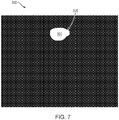
- FIG. 7 illustrates an exemplary image 350 in which a potential position and size of a contrast cloud from a single x-ray frame has been detected.
- a dilated cloud mask 360 is shown with a border or boundary 370. This is used to create a cloud mask of the contrast cloud in step A10.
- the cloud mask can individually and if aggregated define a region of uncertainty respect to which the presence of the contrast cloud. Expanding the mask reduces the likelihood of tracking the probe in the cloud region.
- the cloud region is detected and defined as an exclusion zone in one embodiment.
- steps B1-B4 optional processing steps can be used for fusing cloud masks from multiple images.
- cloud masks from multiple images are used together to create a single fused mask.
- a pixel-wise OR operator can be used to obtain a merged contrast cloud mask incorporating information from multiple x-ray frames, in step B2.
- another component-based filter can be used to remove small components or components that are out of the region of interest in step B3.
- the use of multiple x-ray frames is advantageous given the expansion and dispersal of the cloud over a time period following the contrast solutions initial delivery.
- step B4 the cloud masks from each frame can be fused, as illustrated in FIG. 8 which illustrates an exemplary image 160 of a fused contrast cloud mask 410 from an x-ray image sequence.
- This mask can be generated and applied to the image to identify the contrast cloud regions, which may include a buffer zone around them as a safety factor. These identified contrast cloud regions can then be stored in memory as ignore / avoid regions when performing additional image processing.
- the fused cloud mask of FIG. 8 is derived by taking a pixel wise OR between multiple cloud masks.
- a method for detecting the location of wires, such as thin metallic wires, on x-ray images, for example, x-ray angiography.
- Metallic wires used in the types of procedures described herein can include guidewires or wires with physiological gauges for measuring physiological conditions in the area surrounding the wire.
- a wire with a physiological gauge or detector can be in the form of a pressure wire, or a wire that includes gauges for measuring any other conditions, including but not limited to temperature, magnetism, impedance and electrical current and/or voltage.
- Guidewire extraction methods as described herein can be used to produce stable and consistent vessel centerlines in multiple frames.
- the systems and methods described herein can use guidewire position information to define a consistent and stable position.
- a detected guidewire position is selected to define one of the vessel centerline end-points in all angiography frames.
- the detected guidewire position selected after detection is a distal detected guidewire position.
- a metallic wire can include a physiological measurement gauge, and the location of the wire can be used to automatically associate a measurement from the gauge to its corresponding anatomical position.
- a metallic wire is moved in the x-ray scan area an automatic trajectory extraction can be applied.
- automatic detection of consistent anatomical positions can be accomplished using this method.
- FIG. 9 illustrates a flowchart 500 of a method for detecting a wire in an x-ray image.
- the steps of the process flow can be performed for an x-ray image such as an angiography image or plurality of images such as an angiography sequence or cine.
- image smoothing of the x-ray image, or image sequence is performed to enhance elongated structures in the image.
- This filter is a modified anisotropic diffusion filter where the filter coefficients, at each iteration, are derived from the original image intensities combined with the blob and ridge detector, a Laplacian of Gaussian (LoG).
- the structures being elongated include one or more of vessels, guidewire s, ribs or other edge containing elements in the image data.
- FIG. 10 illustrates an exemplary image of an x-ray image of a vessel with a wire being detected after image smoothing has occurred.
- the image has been enhanced by performing an image smoothing step.
- elongate structures are enhanced.
- the guidewire W is shown to right and has endpoints P1 and P2.
- Two bifurcations B1 and B2 are shown relative to arterial branches A1 and A2.
- a morphological filter s applied to the image that can eliminate wide structures in the image, as shown in FIG. 11A .
- the morphological filter is a bottom hat filter.
- the morphological filter is any filter configured or constrained to enhance or select small scale features such as thin elements.
- FIG. 11A illustrates an exemplary image 600 after a morphological filter has been applied.
- the morphological filter is a bottom hat filter.
- a suitable morphological filter allows for the enhancement of dark elongated elements in the image that have typical scale to the structure element used in a given morphological filter, such as for example, a bottom hat filter.
- the morphological filter can be replaced by a median filter to produce a similar result.
- a ridge enhancing filter or detector or a vessel segmentation filter is applied as shown in FIG. 11B .
- a filter or detector is implemented using a ridge enhancing filter, such as a Frangi filer or other suitable filter, that is applied to the image to enhance ridges in the image, as shown in FIG. 11B .
- a ridge enhancing filter can include a Hessian filter, a Frangi filter, or other ridge or edge detectors.
- FIG. 11B illustrates an exemplary image 605 after the ridge enhancing filter has been applied to enhance the ridge structures in the image.
- a ridge enhancing filter is used for the extraction of thin elongated features in the image.
- the ridge enhancing filter output is thresholded to produce a binary image containing thin and elongated dark elements that appear as bright pixels in the thresholded image.
- step 535 bright areas in the image are rejected by performing adaptive thresholding on the input image as a processing step.
- Metallic wires are radio-opaque, and will appear as dark elongate regions on an x-ray image.
- An adaptive binary threshold is applied in order to reject image areas with intensity values that are not of interest.
- bright areas that have an intensity greater than a threshold associated with an intensity value or range of values corresponding to dark values can be rejected in one embodiment.
- FIG. 12 illustrates an exemplary image 610 in which the bright areas of the image have been rejected as a result of the process of performing an intensity threshold image processing step.
- the ridge enhancing filter output result and the adaptive intensity filter result are merged using a pixel-wise AND operator, to obtain a merged metallic wire mask component.
- the angiography image processing software modules and methods described herein connect and filter wire fragments that are detected in the images.
- the wire can be extracted in fragments, and other components in the image which are not related to the wire can be detected.
- the wire fragments can be joined using a combined measurement of a takeoff angle and a distance between the fragments.
- FIG. 13 illustrates an exemplary image of the wire mask 620 created in step 560.
- the mask 620 is shown with the binary levels, one intensity level is associated with the wire W and the rest of the mask is a dark or black second intensity level corresponding to the background of the image.
- the wire W has endpoints PI, P2, respectively, as shown.
- the mask 620 is displayed after performing a thinning process 560.
- one or more of endpoints P1 and P2 can be used to set an endpoint of a vessel centerline.
- guidewire detection is performed to identify one or more distal guidewire endpoints.
- the one or more distal guidewire endpoints can be selected to define a vessel centerline endpoint.
- the wire masking step is performed prior to tracking the vessel centerline distal end-point in one embodiment.
- the application of the wire mask assists in tracking the distal end-points of the vessel centerline for one or more angiography frames with increased accuracy.
- the identification of contrast cloud regions and avoiding such regions during marker tracking and other image processing steps facilitates having a stable and consistent centerline end-point. In turn, having a stable and consistent end-point increases cross-frame registration accuracy.
- angiography imaging of an artery during an intravascular imaging pullback followed by stent deployment is one such application.
- the heart is a fast-moving organ with complex deformations.
- angiography gives a 2D view of a tortuous 3D system in which vascular tree components, bifurcations, and guidewires, implants, stents and other intravascular imaging devices are overlaid on top of each to create ambiguities and overlapping regions in the angiography image which are not really present in the subject's vasculature.
- Various embodiments of the invention provide methods and systems to perform such a mapping using anatomical landmarks such as for example bends, anchor points and bifurcations as disclosed herein.
- the disclosure also relates to methods of detecting a bifurcation extraction on angiography image.
- Methods for grouping bifurcations from multiple x-ray frames are also disclosed.
- methods of detecting and grouping vessel bends positions from multiple x-ray frames are disclosed.
- Motion estimation for 3D vascular structures can also be performed using the detection methods described herein and tracking of landmarks and their relative movement over time and between frames.
- Methods to improve the accuracy of cross frame registration can be achieved by incorporating detection of anchor points based on bifurcations and bends across different x-ray frames.
- the other detection and exclusion processes described herein can also help improve such cross-frame registration.
- the disclosure relates to methods to register a vascular tree, vascular tree segments or other vascular components that are imaged on a plurality of x-ray frames such as frames of angiography data.
- the methods can use an anchor extraction, bend points or a bifurcation point extraction as a step or stage in a given registration between a first frame and a second frame, for example.
- the methods can use a vessel extraction as a step or stage in a given registration between a first frame and a second frame, for example.
- an angiography image can include one or more bifurcations.
- the disclosure describes image data processing and analysis steps to extract or otherwise identify the bifurcation on a per frame and cross frame basis. In one embodiment, methods are described for grouping bifurcations from multiple x-ray frames.
- the disclosure describes image data processing and analysis steps to extract or otherwise identify the vessel bends on a per frame and on a cross frame basis. In one embodiment, methods are described for grouping vessel bends and bifurcation from multiple x-ray frames.
- a method for registering vascular trees extracted from different contrast enhanced x-ray frames, for example during x-ray angiography is described herein.
- the vessel centerlines are known or treated as known for each of the vascular branches of interest. The process of detecting such centerlines can be performed using various methods as described in US Patent No. 9,351,698 .
- a registration method described herein uses bifurcation points (if they exist) and the bending points (if they exist) as “anchors" for matching anatomical positions between different frames. Once the set of matching "anchor points" is obtained, the registration is based on interpolating for matching positions based on relative geodesic distance as measured along the arc-length of the centerlines. Various distance metrics can be used as appropriate.
- anchors points can be used to generate an estimation of the three-dimensional cardiac motion and deformation.
- These 3-D vessels structures reconstructions at multiple phases of the cardiac cycle are of interest for 3D heart motion understanding.
- the displacements of these anchor points on each view along the image sequences induce a way of computing the motion estimation in the 3D vascular structure. Additional details relating to methods of performing "anchor points" matching for interframe registration of vascular trees are described below and otherwise herein.
- FIG. 14 shows an exemplary process flow 630 suitable for registering points associated with a cardiac system such as vascular trees between a first and a second angiography frame.
- This process flow can be used to detect anatomical features and use them for cross-frame / interframe registration.
- Cross-frame registration can be also accomplished by other anatomical features or anatomical landmarks found along the vessel.
- the method 630 can be used to perform interframe registration of vascular trees as shown.
- the process of detecting anatomical features such as bifurcation points such as the split of an artery into a first and a second blood vessel or bends for a given vascular tree and the associated process of grouping such points can be implemented using various data transformation and image processing steps. Initially, the method determines a sequence of x-ray images and associated centerlines Step C1 for processing such as by user selection or other criteria.
- Centerlines can be determined as described herein. Theses x-ray images undergo preprocessing Step C2. An example of such a preprocessed image 640 is shown in FIG. 15A .
- a skeleton image is generated around each centerline of interest as the preprocessing step.
- Various arterial branches and the associated bends and take off junctions and angles thereof are evident and detectable as a result of the lightening of peripheral features and the darkening of arterial features as shown in FIG. 15A .
- FIG. 15B and 15C are an original angiography image and a skeleton of one the vessels in that image and a portion of its periphery environment, respectfully, after the application of image processing and data analysis in accordance with an illustrative embodiment of the disclosure.
- the skeleton image of FIG. 15C corresponds to the output of Step C3.
- the method includes steps that can be grouped into two processing paths or categories.
- the two processing paths or categories can relate to a first anatomical feature or anatomical landmark and one relating to bifurcations and one relating to bend points.
- the bifurcation related portion of the method includes the steps of detecting bifurcations on all or a subset of all frames Step C4 and grouping of bifurcations by clustering Step C5.
- the bend related portion of the method includes the steps of detecting "bend" points detection on all or a subset of all frames Step C6 and grouping of the detected bend points Step C7. These groupings of bifurcations and bend points are in turn used to perform interframe registration of the vascular trees Step C8 or other vascular structures or subsets thereof.
- any groups of a first anatomical features and a second anatomical feature can be grouped or clustered as described herein and in turn used to perform interframe registration of the vascular trees Step C8 or other vascular structures or subsets thereof.
- performing feature extraction relative to a bifurcation includes various steps.
- detecting the bifurcation such as by performing feature extraction includes applying a shadow removal filter on the original image.
- this filtering is performed using the morphological operation of bottom hat with a large structure element, which reduces the effect of heart shadows, of diaphragm and further enhances vessels.
- the output from the prior step can be processed using a Hessian based filter image.
- the output from the Hessian filtering is adaptively thresholded to generate a binary image.
- a skeleton generating algorithm is applied to the binary image in to obtain a skeleton image.
- the skeleton image can be improved by eliminating small components from the skeleton image.
- the small components are less than about 5 pixels. In one embodiment, the small components are less than about 10 pixels. In one embodiment, the small components are less than about 15 pixels. In one embodiment, the small components are less than about 20 pixels. In one embodiment, the small components are less than about 25 pixels. In one embodiment, the small components are less than about 30 pixels.
- the method can include the step of detecting a set of bifurcations on each frame such as for example on each frame's centerline.
- the bifurcations are identified as junctions in the skeleton.
- elimination of false bifurcation-like features such as vessel crossings and ribs is needed.
- a series of one or more filters is applied as follows.
- a rib filter is applied to reduce any contribution that the rib cage or individual ribs may show up in the image and be misconstrued as part of the vascular tree structure. Ribs are nearly static with respect to vessels that move faster. Any filter that is configured to reduce static elements from the image can be used here to image a rib or other static element.
- a temporal filter is used such the filter operates to take every pixel in the entire image sequence and filter it as if it was a 1D signal.
- An average image is calculated from multiple frames and then deducted from the frame of interest. In this way, a static element such as a rib can be removed from or ignored when performing analysis and image processing on a frame of x-ray image data.
- a vessel crossing filter or detector is applied to an x-ray image frame.
- vessel crossings may appear as two adjacent bifurcations taking off at opposite directions.
- the take-off angle of the branch with respect to the main centerline is used to resolve the occurrence of such vessel crossings and the associated potential for co-registration errors due to the crossing of vessels.
- vessel crossings are also addressed by excluding bifurcations situated on different sides of the main centerline and satisfy the condition of having adjacent take off location along the main centerline and absolute angle difference close to 180°.
- the association or grouping process of an anatomic features such as the bifurcations is based on clustering.
- This clustering or grouping process corresponds to Step C5 from FIG. 14 .
- a cluster refers to a single bifurcation extracted from multiple frames. If the same bifurcation is detected on multiple frames, even if in slightly different positions and orientations, the set of a representative bifurcation across frames should form a cluster indicative of it being the same bifurcation imaged at different times on different frames.
- one or more links or vectors can be identified and measured between clusters. The distance metric between two clusters takes into consideration differences between the bifurcations' features or whatever feature is being evaluated and compared.
- These features can include: angles with respect to the main vessel centerlines, the normalized arc length of the bifurcation and average image intensity along the bifurcations branches, bifurcation scale(or width), absolute angle on the angiography image, and bifurcation lumen shape.
- the foregoing features can be used to identify differences and generate a distance metric to evaluate and compare the clustering behavior of a given feature.
- a bifurcation descriptor space or model is generated using various features.
- the features include one or more of a mean image intensity value on the branch (I values), a branch take-off absolute angle (A values), and a normalized arc length of the branch (S values).
- a similarity measure and or a distance measure/metric can be used to associate data points in feature space.
- An example of such metric can be the Euclidean metric D(C i , C j ) defined below.
- D C i C j sqrt I i ⁇ I j 2 + A i ⁇ A j 2 + S i ⁇ S j 2
- I refers to a mean image intensity
- A refers to an absolute angle of the take-off branch
- S refers to normalized arc length of the branch.
- the indices i and j correspond to different angiography frames i and j.
- Clusters of bifurcation datasets representing the same bifurcation in multiple frames are detected and/or selected.
- the process of detecting / selecting can be performed using feature extraction.
- feature extraction is beneficial given the presence of image noise in the clusters and missing information.
- a bifurcation is detected on multiple image frames such that this set of detections across frames can be clustered together to help validate that bifurcation as being the same one across different frames.
- Feature extraction includes the step of filter excess data such as image noise in one embodiment.
- feature extraction can include the step of completing missing information in one or more clusters such as by interpolation or other processes.
- Clusters of certain size are selected for the next processing step in one embodiment.
- a cluster is identified as of a suitably large size for selection and further processing based on the number of its representatives compared to the set of angiography frames captured during the OCT pullback.
- the clusters are used in a cluster consolidating step. The process of consolidating the clusters generates a set of clusters each having a single representative from each frame of interest.
- FIG. 16A shows a subset of an angiography image with a bifurcation formed from two branches B1 and B2.
- FIG. 16B is a representation of that portion of the vascular system showing a bifurcation as part of a vascular tree and an associated angle ⁇ between a vessel branch and its originating (parent) vessel in accordance with an illustrative embodiment of the disclosure.
- the angle of bifurcation with respect to (parent) vessel branch B1 is shown in the schematic representation of the bifurcation as angle ⁇ .
- the angle ⁇ is formed from the junction of branch B1 and branch B2 and is shown as opening from B1 to B2 by the arrow.
- Theses bifurcations are plotted or otherwise grouped based on the angle and arc length in one embodiment as shown in FIG. 17A .
- FIG. 17A shows a plurality of clusters as generated from plotting a normalized arc length (vertical axis) versus angle measurements (horizontal axis).
- Three clusters of interest are labeled 1, 2 and 3.
- Cluster 1 is to the left of cluster 2 and includes a greater number of data points. The data points are show as circular regions.
- Cluster 3 is above cluster 1 and has a greater number of overlapping data points along a rectangular region span the cluster from its top to bottom.
- a redundancy elimination step is performed.
- FIG. 17B shows the corresponding locus for each cluster on the frame of angiography data that was analyzed to generate the clusters. It is desirable to have a single cluster representative from each frame. Therefore, if a cluster lacks a representative from a frame/s, then as a substitute for the missing information interpolated values based on nearest frames will be used to complete the cluster. Any type of interpolation (Linear, Cyclic, spline-based, curve fit, etc.) can be implemented to complete a cluster or define a boundary for such a cluster.
- the elements of the cluster are the bases for treating such an element as the same element across images in one embodiment.
- Each bifurcation cluster is assigned a quality grade that is used for cluster selection.
- the following factors enter the grade: arc-length standard deviation, normalized arc-length standard deviation, angle difference standard deviation, proximity to other bifurcation clusters (based on distances between centroids of different clusters), average number of redundant bifurcation records per frames, average number of missing bifurcation records per frame. A weighted average including these various factors can be used to generate the grade.
- the clusters with best grades are finally chosen.
- the method also includes a bend related path including steps C6 and C7. Additional details relating to these steps follow.
- a set of anatomical "anchors" are extracted as features based on positions of vessel bends. Vessel bends are defined as points where the vessel changes it direction to create a corner-like structures that exhibits high curvature. At each frame a multi scale curvature or curvature-analog is extracted from the vessel centerlines described earlier.
- the method uses a tracking or shortest path algorithm such as the Viterbi algorithm to determine the positions of each bend in all frames or in a sampling of frames.
- feature extraction is used to detect anatomical and other features or landmarks in a given image frame.
- the feature of a shortest path is extracted from all frames of interest by optimizing a cost criterion that is based on the bend angle size, the bend location along the vessel centerline in terms of arc-length or normalized arc-length, and the angle deviation difference between two bends in consecutive frames.
- the set of bends and bifurcations that span the various frames are used to identify a path or otherwise perform registration between angiography frames in one embodiment.
- solutions are extracted based on the ranking of the associated cost criterion for a given solution.
- a filtering step may be applied to eliminate solution originating from small bends or bends that that display inconsistent positions along the vessel centerline.
- FIG. 18A and 18B depict two angiography frames of multiple vascular trees.
- each frame 700, 705 the three bends were detected from the two x-ray frames.
- Centerline detection was performed on each x-ray frame.
- the resulting detected centerlines are depicted by a white line overlaid on each frame.
- Bending detection was also performed with respect to each x-ray frame.
- the bend positions are shown by white diamonds.
- Three bends are shown in each of the left image frame 700 and right image frame 705 numbered 1, 2, and 3 from the bottom to the top.
- Each vessel centerline traces a path through the artery along bends 3, 2, and 1.
- a position of a particular bend in all angiography frames can be used as an anatomical anchor or reference point to accurately identify cross frame positions.
- anatomic feature detection is performed as part of the preprocessing of the angiography images. In one embodiment, this can be performed to generate certain a priori information relating to the path the imaging probe takes through the blood vessel.
- the generation of line segments such as through a skeleton generation process can be used for feature detection.
- a skeleton is a static object such as one or more line segments created to help trace the blood vessels of a subject being imaged.
- the skeleton based approach can prevent or eliminate certain vessel centerlines being generated that would otherwise pass through a side branch or the imaging probe catheter.
- Generating skeletons provides a method to determine an initial candidate for the geometry of the blood vessel being imaged and side branches and other blood vessels as a map or framework to facilitate centerline generation. By generating skeletons, it is possible to extract points of interest such as bifurcation points and vessel segments, to stabilize tracking of markers and vessel centerlines and to verify tracking quality across frames of angiography image data.
- the process of generating skeletons to detect anatomic features like side branches and vessel geometry is implemented during preprocessing of the angiography images.
- Skeletons can be used for detecting anatomical features such as main bifurcation and extrapolation point.
- skeletons can be used for detecting and generating a smooth vessel centerline.
- skeletons can be used with a shortest path algorithm, such a Viterbi, Dijkstra algorithm or other algorithms to facilitate centerline creation.
- the skeletons can be generated based on preprocessed Hessian images.
- a user selected point on an angiography image relating to a guidewire position can be used to reduce noise and facilitate skeleton generation. In other embodiments, this can be implemented by selecting a point based on image features.
- one or more software modules are used to generate and track a vessel centerline for a given frame of angiography data.
- a vessel centerline also referred to herein as a centerline is a model or simulation that is generated based on an iteratively evaluation of each candidate subset of a frame of angiographic data for marker bands associated with the optical or acoustic sensor or other imaging or data collecting sensor introduced during the angiographic data collection.
- a dynamic program software module such as a software module implementing one or more steps of any suitable shortest or optical path determining algorithm, such as, for example, the Viterbi algorithm can be used to track the marker bands.
- the Viterbi algorithm is used for radiopaque marker tracking.
- the creation and tracking of the centerlines are typically handled by other algorithms or combinations thereof.
- Centerline tracking can be enhanced by using feature detection such as guidewire or landmark detection to define an endpoint of a centerline. By defining a centerline endpoint, cross-frame registration and confidence in centerline determination is advantageously increased.
- arrow heads showing directionality in a given figure or the lack thereof are not intended to limit or require a direction in which information can flow.
- a given connector such as the arrows and lines shown connecting the elements shown in FIG. 1
- information can flow in one or more directions or in only one direction as suitable for a given embodiment.
- the connections can include various suitable data transmitting connections such as optical, wire, power, wireless, or electrical connections.
- the present disclosure also relates to the apparatus for performing the operations herein.
- This apparatus may be specially constructed for the required purposes, or it may comprise a general-purpose computer selectively activated or reconfigured by a computer program stored in the computer.
- Embodiments of the disclosure may be implemented in many different forms, including, but in no way limited to, computer program logic for use with a processor (e.g., a microprocessor, microcontroller, digital signal processor, or general purpose computer), programmable logic for use with a programmable logic device, (e.g., a Field Programmable Gate Array (FPGA) or other PLD), discrete components, integrated circuitry (e.g., an Application Specific Integrated Circuit (ASIC)), or any other means including any combination thereof.
- a processor e.g., a microprocessor, microcontroller, digital signal processor, or general purpose computer
- programmable logic for use with a programmable logic device e.g., a Field Programmable Gate Array (FPGA) or other PLD
- FPGA Field Programmable Gate Array
- ASIC Application Specific Integrated Circuit
- some or all of the processing of the data collected using an OCT probe, an FFR probe, an angiography system, and other imaging and subject monitoring devices and the processor-based system is implemented as a set of computer program instructions that is converted into a computer executable form, stored as such in a computer readable medium, and executed by a microprocessor under the control of an operating system.
- user interface instructions and triggers based upon the completion of a pullback or a co-registration request are transformed into processor understandable instructions suitable for generating OCT data, performing image processing using various and other features and embodiments described above.
- Source code may include a series of computer program instructions implemented in any of various programming languages (e.g., an object code, an assembly language, or a high-level language such as Fortran, C, C++, JAVA, or HTML) for use with various operating systems or operating environments.
- the source code may define and use various data structures and communication messages.
- the source code may be in a computer executable form (e.g., via an interpreter), or the source code may be converted (e.g., via a translator, assembler, or compiler) into a computer executable form.
- the computer program may be fixed in any form (e.g., source code form, computer executable form, or an intermediate form) either permanently or transitorily in a tangible storage medium, such as a semiconductor memory device (e.g., a RAM, ROM, PROM, EEPROM, or Flash-Programmable RAM), a magnetic memory device (e.g., a diskette or fixed disk), an optical memory device (e.g., a CD-ROM), a PC card (e.g., PCMCIA card), or other memory device.
- a semiconductor memory device e.g., a RAM, ROM, PROM, EEPROM, or Flash-Programmable RAM
- a magnetic memory device e.g., a diskette or fixed disk
- an optical memory device e.g., a CD-ROM
- PC card e.g., PCMCIA card
- the computer program may be fixed in any form in a signal that is transmittable to a computer using any of various communication technologies, including, but in no way limited to, analog technologies, digital technologies, optical technologies, wireless technologies (e.g., Bluetooth), networking technologies, and internetworking technologies.
- the computer program may be distributed in any form as a removable storage medium with accompanying printed or electronic documentation (e.g., shrink-wrapped software), preloaded with a computer system (e.g., on system ROM or fixed disk), or distributed from a server or electronic bulletin board over the communication system (e.g., the internet or World Wide Web).
- Hardware logic including programmable logic for use with a programmable logic device
- implementing all or part of the functionality previously described herein may be designed using traditional manual methods, or may be designed, captured, simulated, or documented electronically using various tools, such as Computer Aided Design (CAD), a hardware description language (e.g., VHDL or AHDL), or a PLD programming language (e.g., PALASM, ABEL, or CUPL).
- CAD Computer Aided Design
- a hardware description language e.g., VHDL or AHDL
- PLD programming language e.g., PALASM, ABEL, or CUPL
- Programmable logic may be fixed either permanently or transitorily in a tangible storage medium, such as a semiconductor memory device (e.g., a RAM, ROM, PROM, EEPROM, or Flash-Programmable RAM), a magnetic memory device (e.g., a diskette or fixed disk), an optical memory device (e.g., a CD-ROM), or other memory device.
- a semiconductor memory device e.g., a RAM, ROM, PROM, EEPROM, or Flash-Programmable RAM
- a magnetic memory device e.g., a diskette or fixed disk
- an optical memory device e.g., a CD-ROM
- the programmable logic may be fixed in a signal that is transmittable to a computer using any of various communication technologies, including, but in no way limited to, analog technologies, digital technologies, optical technologies, wireless technologies (e.g., Bluetooth), networking technologies, and internetworking technologies.
- the programmable logic may be distributed as a removable storage medium with accompanying printed or electronic documentation (e.g., shrink-wrapped software), preloaded with a computer system (e.g., on system ROM or fixed disk), or distributed from a server or electronic bulletin board over the communication system (e.g., the internet or World Wide Web).
- printed or electronic documentation e.g., shrink-wrapped software
- a computer system e.g., on system ROM or fixed disk
- server or electronic bulletin board e.g., the internet or World Wide Web
- a module refers to software, hardware, or firmware suitable for performing a specific data processing or data transmission task.
- a module refers to a software routine, program, or other memory resident application suitable for receiving, transforming, routing performing feature extraction and processing instructions, or various types of data such as angiography data, OCT data, IVUS data, cross frame data, pixel coordinates, clusters, clouds, opaque regions, centerlines, shadows, pixels, clusters, distance metrics, intensity patterns, anatomic features, anatomic landmarks, bifurcations, bends, and other information of interest as described herein.
- Computers and computer systems described herein may include operatively associated computer-readable media such as memory for storing software applications used in obtaining, processing, storing and/or communicating data. It can be appreciated that such memory can be internal, external, remote or local with respect to its operatively associated computer or computer system.
- Memory may also include any means for storing software or other instructions including, for example and without limitation, a hard disk, an optical disk, floppy disk, DVD (digital versatile disc), CD (compact disc), memory stick, flash memory, ROM (read only memory), RAM (random access memory), DRAM (dynamic random access memory), PROM (programmable ROM), EEPROM (extended erasable PROM), and/or other like computer- readable media.
- a hard disk an optical disk, floppy disk, DVD (digital versatile disc), CD (compact disc), memory stick, flash memory, ROM (read only memory), RAM (random access memory), DRAM (dynamic random access memory), PROM (programmable ROM), EEPROM (extended erasable PROM), and/or other like computer- readable media.
- computer-readable memory media applied in association with embodiments of the disclosure described herein may include any memory medium capable of storing instructions executed by a programmable apparatus. Where applicable, method steps described herein may be embodied or executed as instructions stored on a computer-readable memory medium or memory media. These instructions may be software embodied in various programming languages such as C++, C, Java, and/or a variety of other kinds of software programming languages that may be applied to create instructions in accordance with embodiments of the disclosure.
- compositions are described as having, including, or comprising specific components, or where processes are described as having, including or comprising specific process steps, it is contemplated that compositions of the present teachings also consist essentially of, or consist of, the recited components, and that the processes of the present teachings also consist essentially of, or consist of, the recited process steps.
- each intervening value between the upper and lower limits of that range or list of values is individually contemplated and is encompassed within the disclosure as if each value were specifically enumerated herein.
- smaller ranges between and including the upper and lower limits of a given range are contemplated and encompassed within the disclosure.
- the listing of exemplary values or ranges is not a disclaimer of other values or ranges between and including the upper and lower limits of a given range.
Claims (10)
- Procédé, à base de dispositif de calcul, de détection de nuage de contraste dans un ensemble de trames d'image d'angiographie, un nuage de contraste étant une région amorphe variant dans le temps, formée pendant l'injection d'un agent de contraste à partir d'une pointe de cathéter conduisant l'agent de contraste, le procédé comprenant :le stockage, dans un dispositif de mémoire électronique, d'un ensemble de trames d'image d'angiographie obtenu pendant une première période de temps qui comprend une ou plusieurs périodes de temps pendant lesquelles une solution de contraste se trouve dans un vaisseau sanguin ;la détection d'une pluralité de régions de nuage de contraste candidates dans une ou plusieurs trames d'image d'angiographie ;la combinaison de la pluralité de régions de nuage de contraste candidates pour générer une région de nuage de contraste fusionnée, la région de nuage de contraste fusionnée ayant une limite de nuage ;la définition d'une zone d'exclusion comme limite du nuage ; etla réduction d'une ou plusieurs erreurs dans un ou plusieurs procédés ultérieurs de traitement de données d'image à base de logiciel, appliqués à une pluralité de trames d'image d'angiographie provenant de l'ensemble de trames d'image d'angiographie en excluant les données d'image d'angiographie situées à l'intérieur de la zone d'exclusion pour qu'elles ne soient pas utilisées par ces un ou plusieurs procédés.
- Procédé selon la revendication 1, où les un ou plusieurs procédés ultérieurs de traitement de données comprennent un recalage de trames croisées de deux trames d'image d'angiographie ou plus de l'ensemble de trames d'image d'angiographie.
- Procédé selon la revendication 2, comprenant en outre la réalisation d'un recalage de trames croisées de deux trames d'image d'angiographie ou plus de l'ensemble de trames d'image d'angiographie.
- Procédé selon la revendication 3, comprenant en outre la génération d'un ensemble de positions de trames croisées.
- Procédé selon la revendication 1, où les un ou plusieurs procédés ultérieurs de traitement de données comprennent un processus choisi dans le groupe constitué par l'extraction de points d'ancrage, l'interpolation de longueurs d'arc ; et la génération de positions de trames croisées.
- Procédé selon la revendication 1, comprenant en outre la dilatation d'une ou plusieurs régions candidates ou de la région de nuage de contraste fusionnée pour fournir une zone d'exclusion étendue et comprenant en outre l'exclusion des données d'image d'angiographie situées au sein de la zone d'exclusion étendue d'un ou plusieurs procédés ultérieurs de traitement de données.
- Procédé selon la revendication 1, comprenant en outre l'affichage d'une pluralité d'images d'angiographie à trames croisées recalées à l'aide d'un système de diagnostic, où la pluralité d'images d'angiographie à trames croisées recalées est sélectionnée dans l'ensemble.
- Procédé selon la revendication 1, où une ou plusieurs étapes du procédé sont mises en œuvre à l'aide d'un système de diagnostic (12) comprenant une entrée pour recevoir l'ensemble provenant d'un système d'angiographie (4), un ou plusieurs dispositifs de mémoire électronique pour stocker l'ensemble, un ou plusieurs dispositifs de calcul en communication électrique avec l'entrée et les un ou plusieurs dispositifs de mémoire, et des instructions, des filtres d'image et des modules logiciels de traitement d'image exécutables par les un ou plusieurs dispositifs de calcul pour réaliser une ou plusieurs étapes du procédé.
- Procédé selon la revendication 1, où les une ou plusieurs erreurs sont une erreur de décalage.
- Procédé selon la revendication 1, comprenant en outre le suivi des mouvements de sonde pour une sonde (30) comprenant un marqueur radio-opaque.
Priority Applications (1)
| Application Number | Priority Date | Filing Date | Title |
|---|---|---|---|
| EP21182661.5A EP3979189A1 (fr) | 2015-11-18 | 2016-11-18 | Systèmes et méthodes de détection et d'enregistrement des caractéristiques d'une image radiographique |
Applications Claiming Priority (2)
| Application Number | Priority Date | Filing Date | Title |
|---|---|---|---|
| US201562257213P | 2015-11-18 | 2015-11-18 | |
| PCT/US2016/062811 WO2017087821A2 (fr) | 2015-11-18 | 2016-11-18 | Détection de caractéristiques d'image radiologique et systèmes et procédés d'enregistrement |
Related Child Applications (2)
| Application Number | Title | Priority Date | Filing Date |
|---|---|---|---|
| EP21182661.5A Division EP3979189A1 (fr) | 2015-11-18 | 2016-11-18 | Systèmes et méthodes de détection et d'enregistrement des caractéristiques d'une image radiographique |
| EP21182661.5A Division-Into EP3979189A1 (fr) | 2015-11-18 | 2016-11-18 | Systèmes et méthodes de détection et d'enregistrement des caractéristiques d'une image radiographique |
Publications (2)
| Publication Number | Publication Date |
|---|---|
| EP3378036A2 EP3378036A2 (fr) | 2018-09-26 |
| EP3378036B1 true EP3378036B1 (fr) | 2021-08-04 |
Family
ID=57570282
Family Applications (2)
| Application Number | Title | Priority Date | Filing Date |
|---|---|---|---|
| EP21182661.5A Pending EP3979189A1 (fr) | 2015-11-18 | 2016-11-18 | Systèmes et méthodes de détection et d'enregistrement des caractéristiques d'une image radiographique |
| EP16813044.1A Active EP3378036B1 (fr) | 2015-11-18 | 2016-11-18 | Détection de caractéristiques d'image radiologique et systèmes et procédés d'enregistrement |
Family Applications Before (1)
| Application Number | Title | Priority Date | Filing Date |
|---|---|---|---|
| EP21182661.5A Pending EP3979189A1 (fr) | 2015-11-18 | 2016-11-18 | Systèmes et méthodes de détection et d'enregistrement des caractéristiques d'une image radiographique |
Country Status (6)
| Country | Link |
|---|---|
| US (6) | US10327726B2 (fr) |
| EP (2) | EP3979189A1 (fr) |
| JP (3) | JP6894896B2 (fr) |
| CN (2) | CN115830332A (fr) |
| CA (1) | CA3005280A1 (fr) |
| WO (1) | WO2017087821A2 (fr) |
Families Citing this family (28)
| Publication number | Priority date | Publication date | Assignee | Title |
|---|---|---|---|---|
| US11278206B2 (en) | 2015-04-16 | 2022-03-22 | Gentuity, Llc | Micro-optic probes for neurology |
| WO2017040484A1 (fr) | 2015-08-31 | 2017-03-09 | Gentuity, Llc | Système d'imagerie comportant une sonde d'imagerie et des dispositifs d'administration |
| CN115830332A (zh) | 2015-11-18 | 2023-03-21 | 光学实验室成像公司 | x射线图像特征检测和配准系统和方法 |
| WO2017197527A1 (fr) * | 2016-05-20 | 2017-11-23 | Perimeter Medical Imaging, Inc. | Procédé et système pour combiner l'imagerie microscopique avec des rayons x |
| US11202679B2 (en) * | 2016-06-22 | 2021-12-21 | Sync-Rx Ltd. | Estimating the endoluminal path of an endoluminal device along a lumen |
| CN109716446B (zh) | 2016-09-28 | 2023-10-03 | 光学实验室成像公司 | 利用血管表象的支架规划系统及方法 |
| US10467786B2 (en) * | 2017-02-28 | 2019-11-05 | General Electric Company | Systems and methods of stent image enhancement |
| US10674985B2 (en) * | 2017-07-26 | 2020-06-09 | Canon U.S.A., Inc. | Method for co-registering and displaying multiple imaging modalities |
| EP3456267A1 (fr) * | 2017-09-14 | 2019-03-20 | Koninklijke Philips N.V. | Traitement d'image par ultrasons |
| WO2019068860A1 (fr) * | 2017-10-06 | 2019-04-11 | Koninklijke Philips N.V. | Dispositifs, systèmes et procédés d'évaluation de débit sanguin à imagerie de perfusion vasculaire |
| JP7160935B2 (ja) | 2017-11-28 | 2022-10-25 | ジェンテュイティ・リミテッド・ライアビリティ・カンパニー | 撮像システム |
| WO2019183843A1 (fr) * | 2018-03-28 | 2019-10-03 | 西安电子科技大学 | Procédé d'alignement inter-trames et de correction de non-uniformités basée sur une taille de pas adaptative pour image infrarouge |
| CN112513930A (zh) | 2018-05-29 | 2021-03-16 | 光实验成像公司 | 支架扩张显示、系统和方法 |
| EP3659514A1 (fr) * | 2018-11-29 | 2020-06-03 | Koninklijke Philips N.V. | Identification et localisation de dispositif à base d'image |
| CN109685846B (zh) * | 2018-12-19 | 2023-03-10 | 吉林大学 | 一种基于Dijkstra的X光照片中金属物定位方法 |
| CN110473143B (zh) * | 2019-07-23 | 2023-11-10 | 平安科技(深圳)有限公司 | 一种三维mra医学图像拼接方法及装置、电子设备 |
| JP7373980B2 (ja) * | 2019-11-29 | 2023-11-06 | キヤノンメディカルシステムズ株式会社 | X線診断装置、およびマーカ検出プログラム |
| KR102272209B1 (ko) * | 2020-01-09 | 2021-07-02 | (주)유아이엠디 | 고배율 촬상을 위한 최적 촬상경로 연산 방법 |
| US11151732B2 (en) * | 2020-01-16 | 2021-10-19 | Siemens Healthcare Gmbh | Motion correction of angiography images for 3D reconstruction of coronary arteries |
| CN111325147A (zh) * | 2020-02-20 | 2020-06-23 | 山东万腾智能科技有限公司 | 一种基于图像处理的定位线夹脱落检测系统及方法 |
| CN111710028B (zh) * | 2020-05-27 | 2023-06-30 | 北京东软医疗设备有限公司 | 三维造影图像的生成方法、装置、存储介质和电子设备 |
| CN112330649B (zh) * | 2020-11-12 | 2022-11-04 | 清华大学 | 结合多光谱和可见光图像的生理信息获取方法和装置 |
| CN112767406B (zh) * | 2021-02-02 | 2023-12-12 | 苏州大学 | 角膜溃疡分割的深度卷积神经网络训练方法及分割方法 |
| CN115511773B (zh) * | 2021-06-21 | 2023-08-29 | 数坤(上海)医疗科技有限公司 | 一种血管中心线提取方法、装置、设备和可读存储介质 |
| CN113516669B (zh) * | 2021-06-23 | 2023-04-25 | 湖北英库科技有限公司 | 一种基于ct影像的气管提取方法、装置、设备及存储介质 |
| US20230054891A1 (en) | 2021-08-19 | 2023-02-23 | Lightlab Imaging, Inc. | Systems And Methods Of Identifying Vessel Attributes Using Extravascular Images |
| CN113616160B (zh) * | 2021-09-14 | 2024-02-06 | 苏州博动戎影医疗科技有限公司 | 基于多模态医学影像的ffr确定方法、装置、设备及介质 |
| CN114782358A (zh) * | 2022-04-18 | 2022-07-22 | 上海博动医疗科技股份有限公司 | 一种血管形变自动计算的方法、装置及存储介质 |
Family Cites Families (145)
| Publication number | Priority date | Publication date | Assignee | Title |
|---|---|---|---|---|
| US5457728A (en) | 1990-11-14 | 1995-10-10 | Cedars-Sinai Medical Center | Coronary tracking display |
| US6485413B1 (en) | 1991-04-29 | 2002-11-26 | The General Hospital Corporation | Methods and apparatus for forward-directed optical scanning instruments |
| US6501551B1 (en) | 1991-04-29 | 2002-12-31 | Massachusetts Institute Of Technology | Fiber optic imaging endoscope interferometer with at least one faraday rotator |
| US6111645A (en) | 1991-04-29 | 2000-08-29 | Massachusetts Institute Of Technology | Grating based phase control optical delay line |
| US5465147A (en) | 1991-04-29 | 1995-11-07 | Massachusetts Institute Of Technology | Method and apparatus for acquiring images using a ccd detector array and no transverse scanner |
| US6134003A (en) | 1991-04-29 | 2000-10-17 | Massachusetts Institute Of Technology | Method and apparatus for performing optical measurements using a fiber optic imaging guidewire, catheter or endoscope |
| US6564087B1 (en) | 1991-04-29 | 2003-05-13 | Massachusetts Institute Of Technology | Fiber optic needle probes for optical coherence tomography imaging |
| US5748598A (en) | 1995-12-22 | 1998-05-05 | Massachusetts Institute Of Technology | Apparatus and methods for reading multilayer storage media using short coherence length sources |
| US5956355A (en) | 1991-04-29 | 1999-09-21 | Massachusetts Institute Of Technology | Method and apparatus for performing optical measurements using a rapidly frequency-tuned laser |
| EP0581871B2 (fr) | 1991-04-29 | 2009-08-12 | Massachusetts Institute Of Technology | Appareil d'imagerie optique et de mesure |
| JPH06165035A (ja) * | 1992-11-24 | 1994-06-10 | Toshiba Corp | X線診断装置 |
| US5509093A (en) | 1993-10-13 | 1996-04-16 | Micron Optics, Inc. | Temperature compensated fiber fabry-perot filters |
| EP1658808A1 (fr) | 1994-09-02 | 2006-05-24 | Volcano Corporation | Capteur de pression ultra-miniaturise et fil de guidage équipe de ce dernier |
| US5619368A (en) | 1995-05-16 | 1997-04-08 | Massachusetts Inst. Of Technology | Optical frequency shifter |
| WO1997001167A1 (fr) | 1995-06-21 | 1997-01-09 | Massachusetts Institute Of Technology | Appareil et procede permettant d'acceder a des donnees enregistrees sur des supports optiques multichouches |
| US6302875B1 (en) | 1996-10-11 | 2001-10-16 | Transvascular, Inc. | Catheters and related devices for forming passageways between blood vessels or other anatomical structures |
| US6047080A (en) * | 1996-06-19 | 2000-04-04 | Arch Development Corporation | Method and apparatus for three-dimensional reconstruction of coronary vessels from angiographic images |
| US6195445B1 (en) | 1997-06-30 | 2001-02-27 | Siemens Corporate Research, Inc. | Motion compensation of an image sequence using optimal polyline tracking |
| US6148095A (en) | 1997-09-08 | 2000-11-14 | University Of Iowa Research Foundation | Apparatus and method for determining three-dimensional representations of tortuous vessels |
| US20020161351A1 (en) | 1998-09-01 | 2002-10-31 | Samson Wilfred J. | Method and apparatus for treating acute myocardial infarction with selective hypothermic perfusion |
| US6621889B1 (en) | 1998-10-23 | 2003-09-16 | Varian Medical Systems, Inc. | Method and system for predictive physiological gating of radiation therapy |
| US6937696B1 (en) | 1998-10-23 | 2005-08-30 | Varian Medical Systems Technologies, Inc. | Method and system for predictive physiological gating |
| US6973202B2 (en) | 1998-10-23 | 2005-12-06 | Varian Medical Systems Technologies, Inc. | Single-camera tracking of an object |
| GB2345543A (en) | 1999-01-06 | 2000-07-12 | Intravascular Res Ltd | Ultrasonic visualisation system with remote components |
| US6191862B1 (en) | 1999-01-20 | 2001-02-20 | Lightlab Imaging, Llc | Methods and apparatus for high speed longitudinal scanning in imaging systems |
| US6445939B1 (en) | 1999-08-09 | 2002-09-03 | Lightlab Imaging, Llc | Ultra-small optical probes, imaging optics, and methods for using same |
| US20030053669A1 (en) * | 2001-07-18 | 2003-03-20 | Marconi Medical Systems, Inc. | Magnetic resonance angiography method and apparatus |
| US7321677B2 (en) | 2000-05-09 | 2008-01-22 | Paieon Inc. | System and method for three-dimensional reconstruction of an artery |
| US6565514B2 (en) | 2000-08-25 | 2003-05-20 | Radi Medical Systems Ab | Method and system for determining physiological variables |
| EP1316066A2 (fr) | 2000-08-31 | 2003-06-04 | Koninklijke Philips Electronics N.V. | Procede et systeme de traitement d'image permettant d'extraire une chaine de points suivant une structure de type filiforme dans une sequence d'images |
| ATE454845T1 (de) | 2000-10-30 | 2010-01-15 | Gen Hospital Corp | Optische systeme zur gewebeanalyse |
| US6768756B2 (en) | 2001-03-12 | 2004-07-27 | Axsun Technologies, Inc. | MEMS membrane with integral mirror/lens |
| US6570659B2 (en) | 2001-03-16 | 2003-05-27 | Lightlab Imaging, Llc | Broadband light source system and method and light source combiner |
| US6552796B2 (en) | 2001-04-06 | 2003-04-22 | Lightlab Imaging, Llc | Apparatus and method for selective data collection and signal to noise ratio enhancement using optical coherence tomography |
| US6706004B2 (en) | 2001-05-31 | 2004-03-16 | Infraredx, Inc. | Balloon catheter |
| US6879851B2 (en) | 2001-06-07 | 2005-04-12 | Lightlab Imaging, Llc | Fiber optic endoscopic gastrointestinal probe |
| US6731973B2 (en) | 2001-06-12 | 2004-05-04 | Ge Medical Systems Information Technologies, Inc. | Method and apparatus for processing physiological data |
| US6728566B1 (en) | 2001-11-21 | 2004-04-27 | Koninklijke Philips Electronics, N.V. | Vessel tracking and tree extraction method and apparatus |
| US7134994B2 (en) | 2002-05-20 | 2006-11-14 | Volcano Corporation | Multipurpose host system for invasive cardiovascular diagnostic measurement acquisition and display |
| US7288244B2 (en) | 2002-07-02 | 2007-10-30 | Nv Thermocore Medical Systems Sa | Determining vulnerable plaque in blood vessels |
| US6891984B2 (en) | 2002-07-25 | 2005-05-10 | Lightlab Imaging, Llc | Scanning miniature optical probes with optical distortion correction and rotational control |
| US7113623B2 (en) * | 2002-10-08 | 2006-09-26 | The Regents Of The University Of Colorado | Methods and systems for display and analysis of moving arterial tree structures |
| US7697972B2 (en) | 2002-11-19 | 2010-04-13 | Medtronic Navigation, Inc. | Navigation system for cardiac therapies |
| US7925327B2 (en) | 2002-12-04 | 2011-04-12 | Koninklijke Philips Electronics N.V. | Apparatus and method for assisting the navigation of a catheter in a vessel |
| US7241286B2 (en) | 2003-04-25 | 2007-07-10 | Lightlab Imaging, Llc | Flush catheter with flow directing sheath |
| US20100076320A1 (en) | 2003-04-25 | 2010-03-25 | Lightlab Imaging, Llc | Flush catheter with flow directing sheath |
| WO2005020790A2 (fr) | 2003-08-21 | 2005-03-10 | Ischem Corporation | Techniques et systemes automatises de detection et d'analyse de plaque vasculaire |
| US8571639B2 (en) | 2003-09-05 | 2013-10-29 | Varian Medical Systems, Inc. | Systems and methods for gating medical procedures |
| US7583829B2 (en) * | 2004-09-13 | 2009-09-01 | Siemens Medical Solutions Usa, Inc. | Method and apparatus for embolism analysis |
| US20060095065A1 (en) | 2004-09-24 | 2006-05-04 | Tetsuaki Tanimura | Fluid occluding devices and methods |
| US7301644B2 (en) | 2004-12-02 | 2007-11-27 | University Of Miami | Enhanced optical coherence tomography for anatomical mapping |
| JP2006167187A (ja) * | 2004-12-16 | 2006-06-29 | Hitachi Medical Corp | 医用画像表示装置 |
| JP5345782B2 (ja) | 2005-01-11 | 2013-11-20 | ヴォルケイノウ・コーポレーション | 血管情報取得装置 |
| EP2838167A1 (fr) | 2005-01-20 | 2015-02-18 | Massachusetts Institute of Technology | Procédés et appareil de verrouillage de mode |
| US8315282B2 (en) | 2005-01-20 | 2012-11-20 | Massachusetts Institute Of Technology | Fourier domain mode locking: method and apparatus for control and improved performance |
| EP1850735A2 (fr) | 2005-02-10 | 2007-11-07 | Lightlab Imaging, Inc. | Appareil de tomographie a coherence optique et procedes associes |
| US7415049B2 (en) | 2005-03-28 | 2008-08-19 | Axsun Technologies, Inc. | Laser with tilted multi spatial mode resonator tuning element |
| ES2337497T3 (es) | 2005-04-28 | 2010-04-26 | The General Hospital Corporation | Evaluacion de caracteristicas de la imagen de una estructura anatomica en imagenes de tomografia de coherencia optica. |
| EP1903944B1 (fr) | 2005-06-24 | 2017-04-19 | Volcano Corporation | Co-registration de donnees d'images graphiques representant des elements vasculaires tridimensionnels |
| DE102005030647B3 (de) | 2005-06-30 | 2007-03-22 | Siemens Ag | Vorrichtung und Verfahren zur intraluminalen Bildgebung für die Rekonstruktion von 3D-Bilddatensätzen |
| CN101288102B (zh) | 2005-08-01 | 2013-03-20 | 拜奥普蒂根公司 | 用于分析从样本所获得的三维数据集的方法和系统 |
| US7379062B2 (en) | 2005-08-01 | 2008-05-27 | Barco Nv | Method for determining a path along a biological object with a lumen |
| US20070135803A1 (en) | 2005-09-14 | 2007-06-14 | Amir Belson | Methods and apparatus for performing transluminal and other procedures |
| DE102005045373A1 (de) | 2005-09-22 | 2007-04-05 | Siemens Ag | Kathetervorrichtung |
| CN101360447B (zh) | 2005-09-29 | 2012-12-05 | 通用医疗公司 | 通过光谱编码进行光学成像的方法和装置 |
| US7988633B2 (en) | 2005-10-12 | 2011-08-02 | Volcano Corporation | Apparatus and method for use of RFID catheter intelligence |
| US7918793B2 (en) | 2005-10-28 | 2011-04-05 | Biosense Webster, Inc. | Synchronization of ultrasound imaging data with electrical mapping |
| US7729746B2 (en) | 2005-11-04 | 2010-06-01 | Siemens Aktiengesellschaft | Three-dimensional co-registration between intravascular and angiographic data |
| WO2007061769A2 (fr) | 2005-11-18 | 2007-05-31 | Duke University | Procede et systeme d'enregistrement de tomographie par coherence optique (tco) avec d'autres essais cliniques |
| US7792342B2 (en) | 2006-02-16 | 2010-09-07 | Siemens Medical Solutions Usa, Inc. | System and method for detecting and tracking a guidewire in a fluoroscopic image sequence |
| JP5161427B2 (ja) * | 2006-02-20 | 2013-03-13 | 株式会社東芝 | 画像撮影装置、画像処理装置及びプログラム |
| DE102006024000A1 (de) * | 2006-05-22 | 2007-11-29 | Siemens Ag | Verfahren und Vorrichtung zum Visualisieren von Objekten |
| US8029447B2 (en) | 2006-10-10 | 2011-10-04 | Volcano Corporation | Multipurpose host system for invasive cardiovascular diagnostic measurement acquisition including an enhanced dynamically configured graphical display |
| EP2074595A1 (fr) | 2006-10-17 | 2009-07-01 | Koninklijke Philips Electronics N.V. | Visualisation d'images tridimensionnelles en association avec des images de projection bidimensionnelle |
| EP2628443B1 (fr) | 2006-11-08 | 2021-05-12 | Lightlab Imaging, Inc. | Dispositif d'imagerie opto-acoustique |
| EP2086415B1 (fr) * | 2006-11-22 | 2011-06-08 | Koninklijke Philips Electronics N.V. | Combinaison de données radiologigues avec des données acquises de manière intravasculaire |
| EP2897239B1 (fr) | 2007-01-10 | 2020-11-18 | Lightlab Imaging, Inc. | Procédés et appareil de tomographie par cohérence optique à balayage de fréquence-source |
| US8781193B2 (en) * | 2007-03-08 | 2014-07-15 | Sync-Rx, Ltd. | Automatic quantitative vessel analysis |
| US9629571B2 (en) | 2007-03-08 | 2017-04-25 | Sync-Rx, Ltd. | Co-use of endoluminal data and extraluminal imaging |
| WO2009153794A1 (fr) | 2008-06-19 | 2009-12-23 | Sync-Rx, Ltd. | Avancement progressif d'un instrument médical |
| EP2129284A4 (fr) | 2007-03-08 | 2012-11-28 | Sync Rx Ltd | Imagerie et outils à utiliser avec des organes mobiles |
| US10716528B2 (en) | 2007-03-08 | 2020-07-21 | Sync-Rx, Ltd. | Automatic display of previously-acquired endoluminal images |
| US8121367B2 (en) * | 2007-09-21 | 2012-02-21 | Siemens Aktiengesellschaft | Method and system for vessel segmentation in fluoroscopic images |
| US8582934B2 (en) | 2007-11-12 | 2013-11-12 | Lightlab Imaging, Inc. | Miniature optical elements for fiber-optic beam shaping |
| US7813609B2 (en) | 2007-11-12 | 2010-10-12 | Lightlab Imaging, Inc. | Imaging catheter with integrated reference reflector |
| US20110190586A1 (en) | 2008-03-28 | 2011-08-04 | Volcano Corporation | Methods and systems for intravascular imaging and flushing |
| WO2009140617A2 (fr) | 2008-05-15 | 2009-11-19 | Axsun Technologies, Inc. | Tomographies par cohérence optique (tco) combinant des sondes et des systèmes intégrés |
| JP2011521747A (ja) | 2008-06-02 | 2011-07-28 | ライトラブ イメージング, インコーポレイテッド | 光コヒーレンストモグラフィ画像から組織特徴を取得する定量的方法 |
| US8423121B2 (en) | 2008-08-11 | 2013-04-16 | Siemens Aktiengesellschaft | Method and system for guidewire tracking in fluoroscopic image sequences |
| DE102008045634A1 (de) | 2008-09-03 | 2010-03-04 | Ludwig-Maximilians-Universität München | Wellenlängenabstimmbare Lichtquelle |
| CA2728662C (fr) | 2008-10-14 | 2020-06-16 | Lightlab Imaging, Inc. | Procedes de detection de support d'endoprothese et de mesure afferente, et affichage au moyen de la tomographie par coherence optique |
| JP5523791B2 (ja) * | 2008-10-27 | 2014-06-18 | 株式会社東芝 | X線診断装置および画像処理装置 |
| US9974509B2 (en) | 2008-11-18 | 2018-05-22 | Sync-Rx Ltd. | Image super enhancement |
| US10362962B2 (en) | 2008-11-18 | 2019-07-30 | Synx-Rx, Ltd. | Accounting for skipped imaging locations during movement of an endoluminal imaging probe |
| US9095313B2 (en) | 2008-11-18 | 2015-08-04 | Sync-Rx, Ltd. | Accounting for non-uniform longitudinal motion during movement of an endoluminal imaging probe |
| US8855744B2 (en) | 2008-11-18 | 2014-10-07 | Sync-Rx, Ltd. | Displaying a device within an endoluminal image stack |
| US9101286B2 (en) | 2008-11-18 | 2015-08-11 | Sync-Rx, Ltd. | Apparatus and methods for determining a dimension of a portion of a stack of endoluminal data points |
| US11064903B2 (en) | 2008-11-18 | 2021-07-20 | Sync-Rx, Ltd | Apparatus and methods for mapping a sequence of images to a roadmap image |
| US9144394B2 (en) | 2008-11-18 | 2015-09-29 | Sync-Rx, Ltd. | Apparatus and methods for determining a plurality of local calibration factors for an image |
| US8953856B2 (en) * | 2008-11-25 | 2015-02-10 | Algotec Systems Ltd. | Method and system for registering a medical image |
| US8457440B1 (en) | 2009-01-27 | 2013-06-04 | Axsun Technologies, Inc. | Method and system for background subtraction in medical optical coherence tomography system |
| US8784800B2 (en) * | 2009-03-09 | 2014-07-22 | Medtronic, Inc. | Method of delivering cell therapy to a target site |
| US9524550B2 (en) * | 2009-05-05 | 2016-12-20 | Siemens Healthcare Gmbh | System and method for coronary digital subtraction angiography |
| US8909323B2 (en) | 2009-08-06 | 2014-12-09 | Siemens Medical Solutions Usa, Inc. | System for processing angiography and ultrasound image data |
| EP3363350B1 (fr) | 2009-09-23 | 2019-12-11 | Lightlab Imaging, Inc. | Morphologie de lumière et systèmes de collecte de données de mesure de résistance vasculaire, appareil et procédés |
| ES2660147T3 (es) | 2009-09-23 | 2018-03-21 | Lightlab Imaging, Inc. | Sistemas de depuración de sangre in vivo en una luz |
| DE102009043069A1 (de) | 2009-09-25 | 2011-04-07 | Siemens Aktiengesellschaft | Visualisierungsverfahren und Bildgebungssystem |
| US20110150309A1 (en) * | 2009-11-27 | 2011-06-23 | University Health Network | Method and system for managing imaging data, and associated devices and compounds |
| US8206377B2 (en) | 2009-12-22 | 2012-06-26 | Lightlab Imaging, Inc. | Torque limiter for an OCT catheter |
| US8926590B2 (en) | 2009-12-22 | 2015-01-06 | Lightlab Imaging, Inc. | Torque limiter for an OCT catheter |
| US8478384B2 (en) | 2010-01-19 | 2013-07-02 | Lightlab Imaging, Inc. | Intravascular optical coherence tomography system with pressure monitoring interface and accessories |
| US8206374B2 (en) | 2010-03-15 | 2012-06-26 | Medtronic Vascular, Inc. | Catheter having improved traceability |
| US8548213B2 (en) * | 2010-03-16 | 2013-10-01 | Siemens Corporation | Method and system for guiding catheter detection in fluoroscopic images |
| JP5666617B2 (ja) | 2010-03-17 | 2015-02-12 | ライトラボ・イメージング・インコーポレーテッド | 干渉センシングおよび画像取得システムのための強度雑音を低減する方法および装置 |
| US9082165B2 (en) * | 2010-05-31 | 2015-07-14 | Dvp Technologies Ltd. | Inspection of region of interest |
| JP6099562B2 (ja) | 2010-07-29 | 2017-03-22 | シンク−アールエックス,リミティド | 管腔内データおよび管腔外画像化の併用 |
| US8699773B2 (en) * | 2010-10-21 | 2014-04-15 | Beth Israel Deaconess Medical Center | Method for image reconstruction using low-dimensional-structure self-learning and thresholding |
| US8355544B2 (en) * | 2011-02-01 | 2013-01-15 | Universidade Da Coruna-Otri | Method, apparatus, and system for automatic retinal image analysis |
| US8582619B2 (en) | 2011-03-15 | 2013-11-12 | Lightlab Imaging, Inc. | Methods, systems, and devices for timing control in electromagnetic radiation sources |
| US9164240B2 (en) | 2011-03-31 | 2015-10-20 | Lightlab Imaging, Inc. | Optical buffering methods, apparatus, and systems for increasing the repetition rate of tunable light sources |
| CN103959043B (zh) | 2011-05-31 | 2016-11-02 | 光学实验室成像公司 | 多模式成像系统、设备和方法 |
| EP2723231A4 (fr) | 2011-06-23 | 2015-02-25 | Sync Rx Ltd | Nettoyage d'arrière-plan luminal |
| US8582109B1 (en) | 2011-08-01 | 2013-11-12 | Lightlab Imaging, Inc. | Swept mode-hopping laser system, methods, and devices for frequency-domain optical coherence tomography |
| US20130051728A1 (en) | 2011-08-31 | 2013-02-28 | Lightlab Imaging, Inc. | Optical Imaging Probes and Related Methods |
| JP5921132B2 (ja) * | 2011-10-17 | 2016-05-24 | 株式会社東芝 | 医用画像処理システム |
| US8581643B1 (en) | 2011-10-28 | 2013-11-12 | Lightlab Imaging, Inc. | Phase-lock loop-based clocking system, methods and apparatus |
| WO2013074800A1 (fr) | 2011-11-16 | 2013-05-23 | Volcano Corporation | Système et procédé de mesure médicale |
| JP6177314B2 (ja) | 2012-05-21 | 2017-08-09 | シンク−アールエックス,リミティド | 管腔内データと管腔外イメージングとの併用 |
| JP6214646B2 (ja) * | 2012-06-22 | 2017-10-18 | コーニンクレッカ フィリップス エヌ ヴェKoninklijke Philips N.V. | 血管造影図における時間的な解剖学的標的タグ付け |
| EP2863802B1 (fr) | 2012-06-26 | 2020-11-04 | Sync-RX, Ltd. | Traitement d'image lié au flux dans les organes luminaux |
| EP2879584B1 (fr) * | 2012-08-03 | 2016-03-30 | Koninklijke Philips N.V. | Recouvrement dépendant de la position d'un dispositif pour cartographie |
| US9858387B2 (en) * | 2013-01-15 | 2018-01-02 | CathWorks, LTD. | Vascular flow assessment |
| US9814433B2 (en) * | 2012-10-24 | 2017-11-14 | Cathworks Ltd. | Creating a vascular tree model |
| US10210956B2 (en) * | 2012-10-24 | 2019-02-19 | Cathworks Ltd. | Diagnostically useful results in real time |
| US8913084B2 (en) | 2012-12-21 | 2014-12-16 | Volcano Corporation | Method and apparatus for performing virtual pullback of an intravascular imaging device |
| JP2016507304A (ja) * | 2013-02-11 | 2016-03-10 | アンジオメトリックス コーポレーション | 物体を検出及び追跡するとともに重ね合わせるシステム |
| US9351698B2 (en) | 2013-03-12 | 2016-05-31 | Lightlab Imaging, Inc. | Vascular data processing and image registration systems, methods, and apparatuses |
| JP5977214B2 (ja) * | 2013-08-23 | 2016-08-24 | ジーイー・メディカル・システムズ・グローバル・テクノロジー・カンパニー・エルエルシー | 画像処理方法および装置並びにプログラム |
| US9547894B2 (en) * | 2013-10-08 | 2017-01-17 | Toshiba Medical Systems Corporation | Apparatus for, and method of, processing volumetric medical image data |
| US9230331B2 (en) * | 2013-10-21 | 2016-01-05 | Samsung Electronics Co., Ltd. | Systems and methods for registration of ultrasound and CT images |
| WO2016128839A1 (fr) * | 2015-02-13 | 2016-08-18 | St. Jude Medical International Holding S.A.R.L. | Amélioration de modèle 3d à base de suivi |
| US10037603B2 (en) * | 2015-05-04 | 2018-07-31 | Siemens Healthcare Gmbh | Method and system for whole body bone removal and vascular visualization in medical image data |
| US9858688B2 (en) * | 2015-06-30 | 2018-01-02 | General Electric Company | Methods and systems for computed tomography motion compensation |
| EP3347857A1 (fr) * | 2015-09-10 | 2018-07-18 | Koninklijke Philips N.V. | Suppression automatique d'éléments d'image |
| CN115830332A (zh) * | 2015-11-18 | 2023-03-21 | 光学实验室成像公司 | x射线图像特征检测和配准系统和方法 |
-
2016
- 2016-11-18 CN CN202211218980.3A patent/CN115830332A/zh active Pending
- 2016-11-18 US US15/355,921 patent/US10327726B2/en active Active
- 2016-11-18 EP EP21182661.5A patent/EP3979189A1/fr active Pending
- 2016-11-18 CA CA3005280A patent/CA3005280A1/fr active Pending
- 2016-11-18 US US15/355,970 patent/US10342502B2/en active Active
- 2016-11-18 CN CN201680067804.0A patent/CN108633312B/zh active Active
- 2016-11-18 JP JP2018525350A patent/JP6894896B2/ja active Active
- 2016-11-18 EP EP16813044.1A patent/EP3378036B1/fr active Active
- 2016-11-18 WO PCT/US2016/062811 patent/WO2017087821A2/fr active Application Filing
- 2016-11-18 US US15/356,013 patent/US10172582B2/en active Active
-
2019
- 2019-06-11 US US16/437,587 patent/US11020078B2/en active Active
-
2021
- 2021-04-08 US US17/225,456 patent/US11633167B2/en active Active
- 2021-06-04 JP JP2021094026A patent/JP7308238B2/ja active Active
-
2023
- 2023-03-23 US US18/125,213 patent/US20230230262A1/en active Pending
- 2023-07-03 JP JP2023108995A patent/JP2023138502A/ja active Pending
Non-Patent Citations (1)
| Title |
|---|
| None * |
Also Published As
| Publication number | Publication date |
|---|---|
| US20190307412A1 (en) | 2019-10-10 |
| US10327726B2 (en) | 2019-06-25 |
| US10342502B2 (en) | 2019-07-09 |
| JP7308238B2 (ja) | 2023-07-13 |
| CA3005280A1 (fr) | 2017-05-26 |
| US11020078B2 (en) | 2021-06-01 |
| JP2021126538A (ja) | 2021-09-02 |
| EP3378036A2 (fr) | 2018-09-26 |
| US20230230262A1 (en) | 2023-07-20 |
| US20170140532A1 (en) | 2017-05-18 |
| US10172582B2 (en) | 2019-01-08 |
| EP3979189A1 (fr) | 2022-04-06 |
| US20210251592A1 (en) | 2021-08-19 |
| WO2017087821A2 (fr) | 2017-05-26 |
| JP2023138502A (ja) | 2023-10-02 |
| CN108633312A (zh) | 2018-10-09 |
| CN108633312B (zh) | 2022-11-08 |
| JP6894896B2 (ja) | 2021-06-30 |
| US20170140531A1 (en) | 2017-05-18 |
| JP2018534074A (ja) | 2018-11-22 |
| CN115830332A (zh) | 2023-03-21 |
| US11633167B2 (en) | 2023-04-25 |
| US20170135663A1 (en) | 2017-05-18 |
| WO2017087821A3 (fr) | 2017-06-22 |
Similar Documents
| Publication | Publication Date | Title |
|---|---|---|
| US11633167B2 (en) | X-ray image feature detection and registration systems and methods | |
| US10687777B2 (en) | Vascular data processing and image registration systems, methods, and apparatuses | |
| EP2967480B1 (fr) | Procédés de traitement de données et d'enregistrement d'images vasculaires | |
| CN108292433B (zh) | 血管内图像中的阴影的检测与验证 | |
| JP7436548B2 (ja) | プロセッサ装置の作動方法 | |
| JP6726714B2 (ja) | 血管内プローブマーカを検出するためのシステムの作動方法、及び血管造影データと、血管に関して取得された血管内データとを重ね合わせ登録するためのシステムの作動方法 |
Legal Events
| Date | Code | Title | Description |
|---|---|---|---|
| STAA | Information on the status of an ep patent application or granted ep patent |
Free format text: STATUS: UNKNOWN |
|
| STAA | Information on the status of an ep patent application or granted ep patent |
Free format text: STATUS: THE INTERNATIONAL PUBLICATION HAS BEEN MADE |
|
| PUAI | Public reference made under article 153(3) epc to a published international application that has entered the european phase |
Free format text: ORIGINAL CODE: 0009012 |
|
| STAA | Information on the status of an ep patent application or granted ep patent |
Free format text: STATUS: REQUEST FOR EXAMINATION WAS MADE |
|
| 17P | Request for examination filed |
Effective date: 20180618 |
|
| AK | Designated contracting states |
Kind code of ref document: A2 Designated state(s): AL AT BE BG CH CY CZ DE DK EE ES FI FR GB GR HR HU IE IS IT LI LT LU LV MC MK MT NL NO PL PT RO RS SE SI SK SM TR |
|
| AX | Request for extension of the european patent |
Extension state: BA ME |
|
| DAV | Request for validation of the european patent (deleted) | ||
| DAX | Request for extension of the european patent (deleted) | ||
| RIN1 | Information on inventor provided before grant (corrected) |
Inventor name: DASCAL, LORINA Inventor name: WINKLER, ITAI |
|
| STAA | Information on the status of an ep patent application or granted ep patent |
Free format text: STATUS: EXAMINATION IS IN PROGRESS |
|
| 17Q | First examination report despatched |
Effective date: 20190411 |
|
| STAA | Information on the status of an ep patent application or granted ep patent |
Free format text: STATUS: EXAMINATION IS IN PROGRESS |
|
| GRAP | Despatch of communication of intention to grant a patent |
Free format text: ORIGINAL CODE: EPIDOSNIGR1 |
|
| STAA | Information on the status of an ep patent application or granted ep patent |
Free format text: STATUS: GRANT OF PATENT IS INTENDED |
|
| INTG | Intention to grant announced |
Effective date: 20210310 |
|
| GRAS | Grant fee paid |
Free format text: ORIGINAL CODE: EPIDOSNIGR3 |
|
| GRAA | (expected) grant |
Free format text: ORIGINAL CODE: 0009210 |
|
| STAA | Information on the status of an ep patent application or granted ep patent |
Free format text: STATUS: THE PATENT HAS BEEN GRANTED |
|
| AK | Designated contracting states |
Kind code of ref document: B1 Designated state(s): AL AT BE BG CH CY CZ DE DK EE ES FI FR GB GR HR HU IE IS IT LI LT LU LV MC MK MT NL NO PL PT RO RS SE SI SK SM TR |
|
| REG | Reference to a national code |
Ref country code: GB Ref legal event code: FG4D |
|
| REG | Reference to a national code |
Ref country code: AT Ref legal event code: REF Ref document number: 1417768 Country of ref document: AT Kind code of ref document: T Effective date: 20210815 |
|
| REG | Reference to a national code |
Ref country code: CH Ref legal event code: EP |
|
| REG | Reference to a national code |
Ref country code: DE Ref legal event code: R096 Ref document number: 602016061701 Country of ref document: DE |
|
| REG | Reference to a national code |
Ref country code: IE Ref legal event code: FG4D |
|
| REG | Reference to a national code |
Ref country code: LT Ref legal event code: MG9D |
|
| REG | Reference to a national code |
Ref country code: NL Ref legal event code: MP Effective date: 20210804 |
|
| REG | Reference to a national code |
Ref country code: AT Ref legal event code: MK05 Ref document number: 1417768 Country of ref document: AT Kind code of ref document: T Effective date: 20210804 |
|
| PG25 | Lapsed in a contracting state [announced via postgrant information from national office to epo] |
Ref country code: PT Free format text: LAPSE BECAUSE OF FAILURE TO SUBMIT A TRANSLATION OF THE DESCRIPTION OR TO PAY THE FEE WITHIN THE PRESCRIBED TIME-LIMIT Effective date: 20211206 Ref country code: NO Free format text: LAPSE BECAUSE OF FAILURE TO SUBMIT A TRANSLATION OF THE DESCRIPTION OR TO PAY THE FEE WITHIN THE PRESCRIBED TIME-LIMIT Effective date: 20211104 Ref country code: HR Free format text: LAPSE BECAUSE OF FAILURE TO SUBMIT A TRANSLATION OF THE DESCRIPTION OR TO PAY THE FEE WITHIN THE PRESCRIBED TIME-LIMIT Effective date: 20210804 Ref country code: ES Free format text: LAPSE BECAUSE OF FAILURE TO SUBMIT A TRANSLATION OF THE DESCRIPTION OR TO PAY THE FEE WITHIN THE PRESCRIBED TIME-LIMIT Effective date: 20210804 Ref country code: FI Free format text: LAPSE BECAUSE OF FAILURE TO SUBMIT A TRANSLATION OF THE DESCRIPTION OR TO PAY THE FEE WITHIN THE PRESCRIBED TIME-LIMIT Effective date: 20210804 Ref country code: LT Free format text: LAPSE BECAUSE OF FAILURE TO SUBMIT A TRANSLATION OF THE DESCRIPTION OR TO PAY THE FEE WITHIN THE PRESCRIBED TIME-LIMIT Effective date: 20210804 Ref country code: AT Free format text: LAPSE BECAUSE OF FAILURE TO SUBMIT A TRANSLATION OF THE DESCRIPTION OR TO PAY THE FEE WITHIN THE PRESCRIBED TIME-LIMIT Effective date: 20210804 Ref country code: BG Free format text: LAPSE BECAUSE OF FAILURE TO SUBMIT A TRANSLATION OF THE DESCRIPTION OR TO PAY THE FEE WITHIN THE PRESCRIBED TIME-LIMIT Effective date: 20211104 Ref country code: SE Free format text: LAPSE BECAUSE OF FAILURE TO SUBMIT A TRANSLATION OF THE DESCRIPTION OR TO PAY THE FEE WITHIN THE PRESCRIBED TIME-LIMIT Effective date: 20210804 Ref country code: RS Free format text: LAPSE BECAUSE OF FAILURE TO SUBMIT A TRANSLATION OF THE DESCRIPTION OR TO PAY THE FEE WITHIN THE PRESCRIBED TIME-LIMIT Effective date: 20210804 |
|
| PG25 | Lapsed in a contracting state [announced via postgrant information from national office to epo] |
Ref country code: PL Free format text: LAPSE BECAUSE OF FAILURE TO SUBMIT A TRANSLATION OF THE DESCRIPTION OR TO PAY THE FEE WITHIN THE PRESCRIBED TIME-LIMIT Effective date: 20210804 Ref country code: LV Free format text: LAPSE BECAUSE OF FAILURE TO SUBMIT A TRANSLATION OF THE DESCRIPTION OR TO PAY THE FEE WITHIN THE PRESCRIBED TIME-LIMIT Effective date: 20210804 Ref country code: GR Free format text: LAPSE BECAUSE OF FAILURE TO SUBMIT A TRANSLATION OF THE DESCRIPTION OR TO PAY THE FEE WITHIN THE PRESCRIBED TIME-LIMIT Effective date: 20211105 |
|
| PG25 | Lapsed in a contracting state [announced via postgrant information from national office to epo] |
Ref country code: NL Free format text: LAPSE BECAUSE OF FAILURE TO SUBMIT A TRANSLATION OF THE DESCRIPTION OR TO PAY THE FEE WITHIN THE PRESCRIBED TIME-LIMIT Effective date: 20210804 |
|
| PG25 | Lapsed in a contracting state [announced via postgrant information from national office to epo] |
Ref country code: DK Free format text: LAPSE BECAUSE OF FAILURE TO SUBMIT A TRANSLATION OF THE DESCRIPTION OR TO PAY THE FEE WITHIN THE PRESCRIBED TIME-LIMIT Effective date: 20210804 |
|
| REG | Reference to a national code |
Ref country code: DE Ref legal event code: R097 Ref document number: 602016061701 Country of ref document: DE |
|
| PG25 | Lapsed in a contracting state [announced via postgrant information from national office to epo] |
Ref country code: SM Free format text: LAPSE BECAUSE OF FAILURE TO SUBMIT A TRANSLATION OF THE DESCRIPTION OR TO PAY THE FEE WITHIN THE PRESCRIBED TIME-LIMIT Effective date: 20210804 Ref country code: SK Free format text: LAPSE BECAUSE OF FAILURE TO SUBMIT A TRANSLATION OF THE DESCRIPTION OR TO PAY THE FEE WITHIN THE PRESCRIBED TIME-LIMIT Effective date: 20210804 Ref country code: RO Free format text: LAPSE BECAUSE OF FAILURE TO SUBMIT A TRANSLATION OF THE DESCRIPTION OR TO PAY THE FEE WITHIN THE PRESCRIBED TIME-LIMIT Effective date: 20210804 Ref country code: EE Free format text: LAPSE BECAUSE OF FAILURE TO SUBMIT A TRANSLATION OF THE DESCRIPTION OR TO PAY THE FEE WITHIN THE PRESCRIBED TIME-LIMIT Effective date: 20210804 Ref country code: CZ Free format text: LAPSE BECAUSE OF FAILURE TO SUBMIT A TRANSLATION OF THE DESCRIPTION OR TO PAY THE FEE WITHIN THE PRESCRIBED TIME-LIMIT Effective date: 20210804 Ref country code: AL Free format text: LAPSE BECAUSE OF FAILURE TO SUBMIT A TRANSLATION OF THE DESCRIPTION OR TO PAY THE FEE WITHIN THE PRESCRIBED TIME-LIMIT Effective date: 20210804 |
|
| PLBE | No opposition filed within time limit |
Free format text: ORIGINAL CODE: 0009261 |
|
| STAA | Information on the status of an ep patent application or granted ep patent |
Free format text: STATUS: NO OPPOSITION FILED WITHIN TIME LIMIT |
|
| PG25 | Lapsed in a contracting state [announced via postgrant information from national office to epo] |
Ref country code: MC Free format text: LAPSE BECAUSE OF FAILURE TO SUBMIT A TRANSLATION OF THE DESCRIPTION OR TO PAY THE FEE WITHIN THE PRESCRIBED TIME-LIMIT Effective date: 20210804 |
|
| REG | Reference to a national code |
Ref country code: CH Ref legal event code: PL |
|
| 26N | No opposition filed |
Effective date: 20220506 |
|
| PG25 | Lapsed in a contracting state [announced via postgrant information from national office to epo] |
Ref country code: LU Free format text: LAPSE BECAUSE OF NON-PAYMENT OF DUE FEES Effective date: 20211118 Ref country code: IT Free format text: LAPSE BECAUSE OF FAILURE TO SUBMIT A TRANSLATION OF THE DESCRIPTION OR TO PAY THE FEE WITHIN THE PRESCRIBED TIME-LIMIT Effective date: 20210804 Ref country code: BE Free format text: LAPSE BECAUSE OF NON-PAYMENT OF DUE FEES Effective date: 20211130 |
|
| REG | Reference to a national code |
Ref country code: BE Ref legal event code: MM Effective date: 20211130 |
|
| PG25 | Lapsed in a contracting state [announced via postgrant information from national office to epo] |
Ref country code: SI Free format text: LAPSE BECAUSE OF FAILURE TO SUBMIT A TRANSLATION OF THE DESCRIPTION OR TO PAY THE FEE WITHIN THE PRESCRIBED TIME-LIMIT Effective date: 20210804 Ref country code: LI Free format text: LAPSE BECAUSE OF NON-PAYMENT OF DUE FEES Effective date: 20211130 Ref country code: CH Free format text: LAPSE BECAUSE OF NON-PAYMENT OF DUE FEES Effective date: 20211130 |
|
| PG25 | Lapsed in a contracting state [announced via postgrant information from national office to epo] |
Ref country code: IE Free format text: LAPSE BECAUSE OF NON-PAYMENT OF DUE FEES Effective date: 20211118 |
|
| PG25 | Lapsed in a contracting state [announced via postgrant information from national office to epo] |
Ref country code: HU Free format text: LAPSE BECAUSE OF FAILURE TO SUBMIT A TRANSLATION OF THE DESCRIPTION OR TO PAY THE FEE WITHIN THE PRESCRIBED TIME-LIMIT; INVALID AB INITIO Effective date: 20161118 |
|
| PG25 | Lapsed in a contracting state [announced via postgrant information from national office to epo] |
Ref country code: CY Free format text: LAPSE BECAUSE OF FAILURE TO SUBMIT A TRANSLATION OF THE DESCRIPTION OR TO PAY THE FEE WITHIN THE PRESCRIBED TIME-LIMIT Effective date: 20210804 |
|
| P01 | Opt-out of the competence of the unified patent court (upc) registered |
Effective date: 20230616 |
|
| PGFP | Annual fee paid to national office [announced via postgrant information from national office to epo] |
Ref country code: GB Payment date: 20231013 Year of fee payment: 8 |
|
| PGFP | Annual fee paid to national office [announced via postgrant information from national office to epo] |
Ref country code: FR Payment date: 20231010 Year of fee payment: 8 Ref country code: DE Payment date: 20231010 Year of fee payment: 8 |