EP3377372B1 - Vehicule terrestre de transport en commun, de type bus, a luminosite amelioree. - Google Patents
Vehicule terrestre de transport en commun, de type bus, a luminosite amelioree. Download PDFInfo
- Publication number
- EP3377372B1 EP3377372B1 EP16805007.8A EP16805007A EP3377372B1 EP 3377372 B1 EP3377372 B1 EP 3377372B1 EP 16805007 A EP16805007 A EP 16805007A EP 3377372 B1 EP3377372 B1 EP 3377372B1
- Authority
- EP
- European Patent Office
- Prior art keywords
- vehicle
- compartment
- technical
- passenger compartment
- upper technical
- Prior art date
- Legal status (The legal status is an assumption and is not a legal conclusion. Google has not performed a legal analysis and makes no representation as to the accuracy of the status listed.)
- Revoked
Links
Images

Classifications
-
- B—PERFORMING OPERATIONS; TRANSPORTING
- B60—VEHICLES IN GENERAL
- B60Q—ARRANGEMENT OF SIGNALLING OR LIGHTING DEVICES, THE MOUNTING OR SUPPORTING THEREOF OR CIRCUITS THEREFOR, FOR VEHICLES IN GENERAL
- B60Q3/00—Arrangement of lighting devices for vehicle interiors; Lighting devices specially adapted for vehicle interiors
- B60Q3/40—Arrangement of lighting devices for vehicle interiors; Lighting devices specially adapted for vehicle interiors specially adapted for specific vehicle types
- B60Q3/41—Arrangement of lighting devices for vehicle interiors; Lighting devices specially adapted for vehicle interiors specially adapted for specific vehicle types for mass transit vehicles, e.g. buses
- B60Q3/43—General lighting
-
- B—PERFORMING OPERATIONS; TRANSPORTING
- B60—VEHICLES IN GENERAL
- B60R—VEHICLES, VEHICLE FITTINGS, OR VEHICLE PARTS, NOT OTHERWISE PROVIDED FOR
- B60R13/00—Elements for body-finishing, identifying, or decorating; Arrangements or adaptations for advertising purposes
- B60R13/02—Internal Trim mouldings ; Internal Ledges; Wall liners for passenger compartments; Roof liners
- B60R13/0275—Internal Trim mouldings ; Internal Ledges; Wall liners for passenger compartments; Roof liners comprising removable or hinged parts
-
- B—PERFORMING OPERATIONS; TRANSPORTING
- B62—LAND VEHICLES FOR TRAVELLING OTHERWISE THAN ON RAILS
- B62D—MOTOR VEHICLES; TRAILERS
- B62D31/00—Superstructures for passenger vehicles
- B62D31/02—Superstructures for passenger vehicles for carrying large numbers of passengers, e.g. omnibus
-
- B—PERFORMING OPERATIONS; TRANSPORTING
- B60—VEHICLES IN GENERAL
- B60H—ARRANGEMENTS OF HEATING, COOLING, VENTILATING OR OTHER AIR-TREATING DEVICES SPECIALLY ADAPTED FOR PASSENGER OR GOODS SPACES OF VEHICLES
- B60H1/00—Heating, cooling or ventilating [HVAC] devices
- B60H1/00357—Air-conditioning arrangements specially adapted for particular vehicles
- B60H1/00371—Air-conditioning arrangements specially adapted for particular vehicles for vehicles carrying large numbers of passengers, e.g. buses
-
- B—PERFORMING OPERATIONS; TRANSPORTING
- B60—VEHICLES IN GENERAL
- B60H—ARRANGEMENTS OF HEATING, COOLING, VENTILATING OR OTHER AIR-TREATING DEVICES SPECIALLY ADAPTED FOR PASSENGER OR GOODS SPACES OF VEHICLES
- B60H1/00—Heating, cooling or ventilating [HVAC] devices
- B60H1/00507—Details, e.g. mounting arrangements, desaeration devices
- B60H1/00557—Details of ducts or cables
- B60H1/00564—Details of ducts or cables of air ducts
-
- B—PERFORMING OPERATIONS; TRANSPORTING
- B60—VEHICLES IN GENERAL
- B60H—ARRANGEMENTS OF HEATING, COOLING, VENTILATING OR OTHER AIR-TREATING DEVICES SPECIALLY ADAPTED FOR PASSENGER OR GOODS SPACES OF VEHICLES
- B60H1/00—Heating, cooling or ventilating [HVAC] devices
- B60H1/24—Devices purely for ventilating or where the heating or cooling is irrelevant
- B60H1/241—Devices purely for ventilating or where the heating or cooling is irrelevant characterised by the location of ventilation devices in the vehicle
- B60H1/245—Devices purely for ventilating or where the heating or cooling is irrelevant characterised by the location of ventilation devices in the vehicle located in the roof
-
- B—PERFORMING OPERATIONS; TRANSPORTING
- B60—VEHICLES IN GENERAL
- B60Q—ARRANGEMENT OF SIGNALLING OR LIGHTING DEVICES, THE MOUNTING OR SUPPORTING THEREOF OR CIRCUITS THEREFOR, FOR VEHICLES IN GENERAL
- B60Q2500/00—Special features or arrangements of vehicle interior lamps
- B60Q2500/20—Special features or arrangements of vehicle interior lamps associated with air conditioning arrangements
-
- B—PERFORMING OPERATIONS; TRANSPORTING
- B60—VEHICLES IN GENERAL
- B60Q—ARRANGEMENT OF SIGNALLING OR LIGHTING DEVICES, THE MOUNTING OR SUPPORTING THEREOF OR CIRCUITS THEREFOR, FOR VEHICLES IN GENERAL
- B60Q3/00—Arrangement of lighting devices for vehicle interiors; Lighting devices specially adapted for vehicle interiors
- B60Q3/70—Arrangement of lighting devices for vehicle interiors; Lighting devices specially adapted for vehicle interiors characterised by the purpose
- B60Q3/74—Arrangement of lighting devices for vehicle interiors; Lighting devices specially adapted for vehicle interiors characterised by the purpose for overall compartment lighting; for overall compartment lighting in combination with specific lighting, e.g. room lamps with reading lamps
-
- B—PERFORMING OPERATIONS; TRANSPORTING
- B60—VEHICLES IN GENERAL
- B60Y—INDEXING SCHEME RELATING TO ASPECTS CROSS-CUTTING VEHICLE TECHNOLOGY
- B60Y2200/00—Type of vehicle
- B60Y2200/10—Road Vehicles
- B60Y2200/14—Trucks; Load vehicles, Busses
- B60Y2200/143—Busses
-
- B—PERFORMING OPERATIONS; TRANSPORTING
- B61—RAILWAYS
- B61D—BODY DETAILS OR KINDS OF RAILWAY VEHICLES
- B61D27/00—Heating, cooling, ventilating, or air-conditioning
- B61D27/009—Means for ventilating only
Definitions
- the present invention relates to a land vehicle for public transport, of the bus or tram-bus type, the brightness of which in the passenger compartment is improved.
- the field of the invention is the field of land vehicles, in particular electric vehicles, public transport, bus, coach or tram-bus type.
- the passenger compartments of public transport vehicles, of the bus or tram type generally comprise one or more technical compartments accessible from the interior of said passenger compartment.
- These technical compartments can take various forms. However, in most cases, these technical compartments are in the form of longitudinal conduits arranged on a side wall of the passenger compartment and more particularly at a junction of the side wall with the upper wall, in other words at the level an upper corner of the passenger compartment.
- the document US 6,416,116 B1 describes a land vehicle for public transport comprising a passenger compartment and several technical compartments accessible from said passenger compartment arranged on / in the upper wall of said passenger compartment and each being in the form of a longitudinal duct.
- An object of the present invention is to remedy these drawbacks.
- Another object of the invention is to provide a vehicle whose natural light within the passenger compartment can be improved.
- the invention makes it possible to achieve at least one of these aims by a land public transport vehicle, in particular of the bus type, according to claim 1.
- the technical compartment or compartments are arranged in / on the upper wall and not at the level of the upper part of a side wall or of a junction of the side wall with the upper wall, as is the case in public transport vehicles known to date.
- the vehicle according to the invention it is possible not to occupy the upper part of at least one, in particular of each, side wall with a technical compartment, this part then being able to be arranged at least in part transparent. , or have one or more panes, so as to allow natural light into the passenger compartment.
- the interior light level is then improved.
- the vehicle according to the invention then uses less synthetic light in the passenger compartment, which reduces its electrical consumption and increases the range of the vehicle when it is an electric vehicle.
- the ergonomics of the vehicle are also improved for users, since natural light is more beneficial to them than synthetic light.
- ram-bus is meant a land-based electric public transport vehicle mounted on wheels and which is recharged at each station, so as not to require heavy infrastructure such as rails, catenaries, on the roads.
- Such an electric vehicle is recharged at each station by means of charging elements of the station and a connector connecting said vehicle to said station.
- At least one, in particular each, upper technical compartment can be arranged at a central zone of the upper wall.
- the central zone of the upper wall constitutes an adequate zone making it possible to cover, in an efficient and centralized manner, the entire interior, when the technical compartment is a ventilation, lighting or display duct. .
- the central area is located in a part of the passenger compartment where the height between the floor and the passenger compartment ceiling can be personalized more easily compared with other areas of the passenger compartment.
- At least one, in particular each, upper technical compartment may be in the form of a longitudinal duct extending in the longitudinal direction of said passenger compartment, over at least part of the length of said passenger compartment.
- Such a technical compartment makes it possible to cover the entire passenger compartment effectively and can for example be used to connect the front part of the passenger compartment to the rear part of the passenger compartment.
- the vehicle according to the invention may, in a non-limiting embodiment, comprise several upper technical compartments, each in the form of a longitudinal duct, extending in the longitudinal direction of said passenger compartment, for example substantially parallel between them, in particular over at least part of the length of said passenger compartment.
- the vehicle according to the invention may comprise a first upper longitudinal duct serving for ventilation of the passenger compartment, a second upper longitudinal duct serving for lighting, a third upper longitudinal duct serving for the display, a fourth upper longitudinal conduit for the passage of electric cables, etc. At least two of these conduits can be parallel to each other and have the same length or different lengths.
- At least one upper technical compartment may comprise longitudinal side vents allowing the passage of air from the outside to the inside of said vehicle.
- the vehicle comprises several upper technical compartments
- at least two upper technical compartments may be adjacent.
- At least two adjacent upper technical compartments may have a common wall, so as to lighten said compartments and reduce the cost of producing said compartments.
- the vehicle according to the invention may comprise at least one, in particular two, longitudinal side wall (s) the upper part of which, in particular at the junction with the upper wall, is at least partly transparent, or comprises at least one window or skylight, allowing the passage of light towards the interior of the passenger compartment.
- At least one upper technical compartment can be provided with a rotary cover between a closed position, preventing access to said upper technical compartment, and an open position, allowing access to said upper technical compartment.
- At least one upper technical compartment may be provided with at least one means for holding the cover of said compartment in the open position.
- Such a holding means may comprise a support piece against which the cover bears when it is in the open position.
- Such a holding means may alternatively comprise a means for retaining the cover of the spring or jack type actuated either independently of the rotation of the cover or during the cover rotation.
- Such a means for holding in the open position may also include a counterweight suitably arranged on the cover.
- Such a holding means makes the intervention of an operator even more ergonomic. Indeed, the cover being held in the open position by the holding means, the operator does not have to worry about it during his intervention.
- At least one technical compartment can be provided with at least one means for locking the cover of said compartment in the closed position.
- Such a locking means can for example be a lock which cannot be locked or unlocked without a key.
- Such a locking means makes it possible to prohibit access to the technical compartment to unauthorized persons.
- At least one upper technical compartment can be provided with several covers.
- At least one of said covers can be opened independently of the other covers, so as to allow access to part of said upper technical compartment.
- At least one upper technical compartment may comprise at least one cable or fluid passage opening, or even a communication opening with another compartment, technical or not, located in the passenger compartment or outside of the passenger compartment.
- At least one technical compartment of the vehicle can be made of plastic or metal.
- at least one rotary cover of at least one technical compartment can be made of plastic or metal.
- the vehicle according to the invention can be a bus, a coach or a tram-bus, in particular electric.
- variants of the invention comprising only a selection of characteristics described below, isolated from the other characteristics described, if this selection of characteristics is sufficient to confer a technical advantage or to differentiate the invention from of the prior art.
- This selection comprises at least one characteristic, preferably functional, without structural details, or with only a part of the structural details if this part is only sufficient to confer a technical advantage or to differentiate the invention from the state of the prior art.
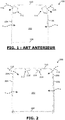
- the FIGURE 1 is a partial schematic representation of an embodiment of a vehicle according to the prior art.
- Vehicle 100 is shown in the FIGURE 1 , in a very simplified manner, in a sectional view along a cutting plane perpendicular to the longitudinal direction of the vehicle, in order to facilitate understanding.
- the vehicle 100 comprises a passenger compartment 102 delimited by two longitudinal side walls 104 and 106 which are substantially vertical, a lower wall 108 and an upper wall 110 which are substantially horizontal.
- the rear wall respectively the front wall, delimiting the passenger compartment at the rear, respectively at the front, are not shown.
- the vehicle 100 comprises, arranged in the passenger compartment, a technical compartment 112 disposed at an upper corner of the passenger compartment 102 at the junction between the side wall 104 and the upper wall 110.
- the vehicle comprises a technical compartment 114 disposed at an upper corner of the passenger compartment 102 at the junction between the wall lateral 106 and the upper wall 110.
- the technical compartments 112 and 114 are opaque and constitute an obstacle to the entry, into the passenger compartment 102 of the vehicle 100, of the external natural light materialized by the dotted arrows 116 and 118.
- FIGURES 2-4 are partial schematic representations of an example of a vehicle not belonging to the invention.
- the vehicle 200 according to the invention is shown in the FIGURE 2 in a very simplified manner, in a sectional view along a cutting plane perpendicular to the longitudinal direction of the vehicle, in order to facilitate understanding.
- the vehicle 200 comprises, like the vehicle 100 of the FIGURE 1 , a passenger compartment 202, longitudinal side walls 204 and 206, a lower wall 208 and an upper wall 210.
- Vehicle 200 of the FIGURE 2 further includes two technical compartments 212 and 214, similar or identical to technical compartments 112 and 114 of the vehicle 100 of the FIGURE 1 .
- the technical compartments 212 and 214 are arranged on the upper wall 210 of the passenger compartment 202, at a central zone of said upper wall 210.
- the upper corner of the passenger compartment 202, at the junction between the side wall 204 and the upper wall 210, is released and the natural light materialized by the arrow 116 can enter the passenger compartment 202 through a window or a skeleton 204 1 (shown in dotted lines on the FIGURE 2 ) arranged at the upper part of the side wall 204.
- the upper corner of the passenger compartment 202, at the junction between the side wall 206 and the upper wall 210 is released and natural light materialized by the arrow 118 can enter the passenger compartment 202 through a window or a skylight 206 1 (shown in dotted lines on the FIGURE 2 ) fitted at the upper part of the side wall 206.
- the level of brightness in the passenger compartment 202 of the vehicle 200 is improved compared to the brightness level of the passenger compartment 102 of the vehicle 100, since it receives an almost vertical light coming from outside therefore more effective for the brightness of the passenger compartment , in addition to the almost horizontal light rays (also represented by dotted arrows on the FIGURE 2 ) on the vertical windows of the vehicle walls.
- FIGURE 8 gives a schematic representation of a vehicle 800 according to this alternative.
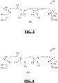
- FIGURES 3 and 4 give schematic representations of the upper wall 210 of the vehicle 200 of the FIGURE 2 fitted with technical compartments.
- Each technical compartment 212-214 is in the form of a longitudinal duct arranged on the upper wall 210, at the level of a central zone of said upper wall 210.
- Each longitudinal technical duct 212-214 extends substantially horizontally, over at least part of, in particular over the entire length of the upper wall 210.
- Each technical duct 212-214 is provided with a cover, respectively 216 and 218.
- Each cover 216-218 is provided for rotation about a longitudinal horizontal axis between a closed position, preventing access to the interior of the technical duct 212 -214, and an open position, allowing access to the interior of the technical duct 212-214.
- the FIGURE 3 is a schematic representation of the technical conduits 212-214 of vehicle 200 of the FIGURE 2 with covers 216-218 of conduits 212-214 in the closed position.
- the FIGURE 4 is a schematic representation of the technical conduits 212-214 of vehicle 200 of the FIGURE 2 with the cover 216 of the duct 212 in the open position and the cover 218 of the technical duct 214 in the closed position.
- Each technical conduit 212-214 comprises a lock making it possible to lock the cover 216-218 of said conduit 212-214 in the closed position against the rest of the technical conduit 212-214.
- Each technical conduit 212-214 further comprises means for holding (not shown) the cover 216-218 of said conduit 212-214 in the open position.
- a means for holding the cover in the open position comprises any combination of the following elements: a jack, a spring, a counterweight or a stop piece.
- each technical conduit of a vehicle according to the invention can be used for a passage of cables or pipes, to convey a fluid such as air conditioning, to house a display means and / or a means lighting, etc.
- the upper technical ducts 212-214 can be used for ventilation within the passenger compartment 202 of the vehicle 200.
- the number and arrangement of the upper technical conduits on the upper wall 210 is not limited to what has just been described with reference to FIGURES 2-4 .
- the FIGURES 5-7 give other examples of embodiment.
- FIGURE 5 is a partial schematic representation of an embodiment of a vehicle according to the invention.
- FIGURE 5 gives a partial representation of the upper wall of a vehicle 500 according to the invention.
- Vehicle 500 includes all elements of vehicle 200 from FIGURES 2-4 .
- the vehicle 500 comprises a longitudinal upper technical conduit 502 disposed between the technical conduits 212 and 214.
- the longitudinal upper technical conduit 502 is arranged between the technical conduits 212 and 214 so that the three conduits 502, 212 and 214 are adjacent.
- the adjacent conduits 502 and 212 have a common side wall.
- the conduits 502 and 214 also have a common side wall.
- the duct 502 can be similar or identical, or even different from the ducts 212 and 214.
- the technical duct 502 is a duct used for lighting the passenger compartment and the ducts 212-214 are used for ventilation within the passenger compartment of the vehicle 500.
- the conduit 502 can be used to house an artificial lighting of the passenger compartment 202, for example an electric lighting produced by LED.
- the conduit 502 can be used to allow natural light to enter the passenger compartment 202, in combination with a roof, at least in part, transparent.
- FIGURE 6 is a partial schematic representation of another embodiment of a vehicle not belonging to the invention.
- FIGURE 6 gives a partial representation of the upper wall of a vehicle 600 according to the invention.
- the vehicle 600 only comprises the upper technical duct 502 of the vehicle 500 of the
- FIGURE 5 Vehicle 600 does not include technical conduits 212 and 214.
- FIGURE 7 is a partial schematic representation of another embodiment of a vehicle not belonging to the invention.
- FIGURE 7 gives a partial representation of the upper wall of a vehicle 700 according to the invention.
- the vehicle 700 only comprises the upper technical duct 212 of the vehicle 500 of the
- FIGURE 5 Vehicle 700 does not include technical conduits 214 and 502.
- FIGURE 8 is a schematic representation of another exemplary embodiment not belonging to the invention.
- FIGURE 8 gives a partial representation of the upper wall of a vehicle 700 according to the invention.
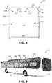
- FIGURE 9 is a schematic representation of an embodiment of a vehicle according to the invention, seen from the outside of the passenger compartment of said vehicle.
- the vehicle 900 shown in the FIGURE 9 is a bus, which comprises transparent panes 902 at the junction between the side wall 204 and the upper wall 210, allowing the passage of light from the outside to the inside of said bus 900.
- the panes 902 are arranged on only part of the bus 900, and more particularly at the level of a central zone bus 900.
- At least one technical compartment of the vehicle according to the invention can be made of plastic or metal.
- at least one rotary cover of at least one technical compartment can be made of plastic or metal.
- vehicle according to the invention may comprise at least one additional technical compartment different from the upper technical compartment or compartments which have just been described.
Landscapes
- Engineering & Computer Science (AREA)
- Mechanical Engineering (AREA)
- Chemical & Material Sciences (AREA)
- Combustion & Propulsion (AREA)
- Transportation (AREA)
- Body Structure For Vehicles (AREA)
- Arrangements Of Lighting Devices For Vehicle Interiors, Mounting And Supporting Thereof, Circuits Therefore (AREA)
- Vehicle Step Arrangements And Article Storage (AREA)
Description
- La présente invention concerne un véhicule terrestre de transport en commun, de type bus ou tram-bus, dont la luminosité dans l'habitacle est améliorée.
- Le domaine de l'invention est le domaine des véhicules terrestres, en particulier des véhicules électriques, de transport en commun, de type bus, car ou tram-bus.
- Les habitacles de véhicules de transport en commun, de type bus ou tram, comprennent généralement un ou plusieurs compartiments techniques accessibles depuis l'intérieur dudit habitacle. Ces compartiments techniques peuvent se présenter sous différentes formes. Néanmoins, dans la plupart des cas, ces compartiments techniques se présentent sous la forme de conduits longitudinaux disposés sur une paroi latérale de l'habitacle et plus particulièrement au niveau d'une jonction de la paroi latérale avec la paroi supérieure, autrement dit au niveau d'un coin supérieur de l'habitacle.
- Par exemple, le document
US 6 416 116 B1 décrit un véhicule terrestre de transport en commun comprenant un habitacle et plusieurs compartiments techniques accessibles depuis ledit habitacle agencés sur/dans la paroi supérieure dudit habitacle et se présentant, chacun, sous la forme d'un conduit longitudinal. - Or, lorsqu'un compartiment technique est disposé au niveau d'un coin supérieur de l'habitacle cela diminue la quantité de lumière entrant dans l'habitacle, car le compartiment technique constitue un obstacle à l'entrée de la lumière extérieure vers l'intérieur de l'habitacle. De ce fait, la plupart des véhicules de transport en commun souffre d'un niveau de luminosité naturelle faible qui doit être compensé par un apport de lumière par éclairage, et ce même en pleine journée.
- Cela a pour conséquence une consommation accrue d'énergie électrique au sein de l'habitacle, ce qui a un coût non négligeable. De plus, dans le cas de véhicules électriques, cela diminue l'autonomie du véhicule.
- Un but de la présente invention est de remédier à ces inconvénients.
- Un autre but de l'invention est de proposer un véhicule dont la luminosité naturelle au sein de l'habitacle peut être améliorée.
- Il est aussi un autre but de l'invention de proposer un véhicule dont la consommation électrique est diminuée et/ou dont l'autonomie électrique est augmentée.
- L'invention permet d'atteindre au moins l'un de ces buts par un véhicule terrestre de transport en commun, en particulier de type bus, selon la revendication 1.
- Ainsi, dans le véhicule selon l'invention, le ou les compartiments techniques (ou au moins une partie des compartiments techniques) sont agencés dans/sur la paroi supérieure et non au niveau de la partie haute d'une paroi latérale ou d'une jonction de la paroi latérale avec la paroi supérieure, tel que c'est le cas dans les véhicules de transport en commun connus à ce jour.
- Par conséquent, dans le véhicule selon l'invention, il est possible de ne pas occuper la partie supérieure d'au moins une, en particulier de chaque, paroi latérale avec un compartiment technique, cette partie pouvant alors être agencée au moins en partie transparente, ou comporter une ou des vitres, de sorte à laisser passer la lumière naturelle dans l'habitacle. Le niveau de luminosité de l'habitacle est alors amélioré. De plus, le véhicule selon l'invention utilise alors moins de lumière synthétique dans l'habitacle, ce qui diminue sa consommation électrique et augmente l'autonomie du véhicule lorsqu'il s'agit d'un véhicule électrique. De plus, l'ergonomie du véhicule est aussi améliorée pour les utilisateurs, car la lumière naturelle leur est plus bénéfique que la lumière synthétique.
- Il est à noter que, selon l'invention, par compartiment technique, on entend un compartiment :
- d'aération,
- d'éclairage,
- d'affichage, et/ou
- de passage de tuyaux ou de câbles électriques.
- De plus, par « tram-bus », on entend un véhicule électrique terrestre de transport en commun monté sur roues et qui se recharge à chaque station, afin de ne pas nécessiter des infrastructures lourdes de type rails, caténaires, sur la voirie. Un tel véhicule électrique se recharge à chaque station au moyen d'éléments de charge de la station et d'un connecteur reliant ledit véhicule à ladite station.
- De manière préférentielle, au moins un, en particulier chaque, compartiment technique supérieur peut être agencé au niveau d'une zone centrale de la paroi supérieure.
- Ainsi, l'obstacle que pourraient former ces compartiments techniques au passage de la lumière naturelle vers l'habitacle est diminué, voire annulé.
- De plus, la zone centrale de la paroi supérieure constitue une zone adéquate permettant de couvrir, de manière efficace et centralisée, l'ensemble de l'habitacle, lorsque le compartiment technique est un conduit d'aération, d'éclairage ou d'affichage.
- Plus encore, la zone centrale se trouve dans une partie de l'habitacle où la hauteur entre le plancher et le plafond de l'habitacle peut être personnalisée plus facilement comparée à d'autres zones de l'habitacle.
- Dans une version particulièrement préférée du véhicule selon l'invention, au moins un, en particulier chaque, compartiment technique supérieur peut se présenter sous la forme d'un conduit longitudinal se prolongeant dans le sens longitudinal dudit habitacle, sur au moins une partie de la longueur dudit habitacle.
- Un tel compartiment technique permet de couvrir l'ensemble de l'habitacle de manière efficace et peut par exemple servir à connecter la partie avant de l'habitacle à la partie arrière de l'habitacle.
- Le véhicule selon l'invention peut, dans un mode de réalisation nullement limitatif, comprendre plusieurs compartiments techniques supérieurs, se présentant chacun sous la forme d'un conduit longitudinal, se prolongeant dans le sens longitudinal dudit habitacle, par exemple de manière sensiblement parallèle entre eux, en particulier sur au moins une partie de la longueur dudit habitacle.
- Par exemple, le véhicule selon l'invention peut comprendre un premier conduit longitudinal supérieur servant à l'aération de l'habitacle, un deuxième conduit longitudinal supérieur servant à l'éclairage, un troisième conduit longitudinal supérieur servant à l'affichage, un quatrième conduit longitudinal supérieur servant au passage de câbles électriques, etc. Au moins deux de ces conduits peuvent être parallèles entre eux et présenter la même longueur ou des longueurs différentes.
- Avantageusement, au moins un compartiment technique supérieur peut comprendre des évents latéraux longitudinaux permettant le passage d'air de l'extérieur vers l'intérieur dudit véhicule.
- Le véhicule selon l'invention comprend :
- deux compartiments techniques supérieurs d'aération, et
- un compartiment technique supérieur d'éclairage, positionné entre lesdits compartiments techniques supérieurs d'aération ;
- Par ailleurs, lorsque le véhicule comprend plusieurs compartiments techniques supérieurs, au moins deux compartiments techniques supérieurs peuvent être adjacents.
- Dans ce cas, au moins deux compartiments techniques supérieurs adjacents peuvent comporter une paroi commune, de sorte à alléger lesdits compartiments et diminuer le coût de réalisation desdits compartiments.
- Avantageusement, le véhicule selon l'invention peut comprendre au moins une, en particulier deux, paroi(s) latérale(s) longitudinale(s) dont la partie supérieure, en particulier au niveau de la jonction avec la paroi supérieure, est au moins en partie transparente, ou comprend au moins une vitre ou claire-voie, autorisant le passage de la lumière vers l'intérieur de l'habitacle.
- Ainsi, le niveau de lumière entrant dans l'habitacle est augmenté.
- De plus, au moins un compartiment technique supérieur peut être pourvu d'un couvercle rotatif entre une position fermée, interdisant l'accès audit compartiment technique supérieur, et une position ouverte, autorisant l'accès audit compartiment technique supérieur.
- Au moins un compartiment technique supérieur peut être pourvu d'au moins un moyen de maintien du couvercle dudit compartiment en position ouverte.
- Un tel moyen de maintien peut comprendre une pièce d'appui contre laquelle le couvercle vient en appui lorsqu'il est en position ouverte.
- Un tel moyen de maintien peut alternativement comprendre un moyen de retenue du couvercle de type ressort ou vérin actionné soit indépendamment de la rotation du couvercle soit lors de la rotation de couvercle.
- Un tel moyen de maintien en position ouverte peut également comprendre un contrepoids adéquatement agencé sur le couvercle.
- Un tel moyen de maintien permet de rendre l'intervention d'un opérateur encore plus ergonomique. En effet, le couvercle étant maintenu en position ouverte par le moyen de maintien, l'opérateur n'a pas à s'en soucier lors de son intervention.
- Selon l'invention, au moins un compartiment technique peut être pourvu d'au moins un moyen de verrouillage du couvercle dudit compartiment en position fermée.
- Un tel moyen de verrouillage peut être par exemple une serrure qui ne peut être verrouillée ou déverrouillée sans clef.
- Un tel moyen de verrouillage permet d'interdire l'accès au compartiment technique à des personnes non autorisées.
- Par ailleurs, au moins un compartiment technique supérieur peut être pourvu de plusieurs couvercles.
- Dans ce cas, au moins un desdits couvercles peut être ouvert indépendamment des autres couvercles, de sorte à laisser accès à une partie dudit compartiment technique supérieur.
- Par ailleurs, au moins un compartiment technique supérieur peut comprendre au moins une ouverture de passage de câble ou de fluide, ou encore une ouverture de communication avec un autre compartiment, technique ou non, se trouvant dans l'habitacle ou à l'extérieur de l'habitacle.
- Selon l'invention, au moins un compartiment technique du véhicule peut être réalisé en plastique ou en métal. De même, au moins un couvercle rotatif d'au moins un compartiment technique peut être réalisé en plastique ou en métal.
- Dans une version préférée, le véhicule selon l'invention peut être un bus, un car ou un tram-bus, en particulier électrique.
- D'autres avantages et caractéristiques apparaîtront à l'examen de la description détaillée d'un mode de réalisation nullement limitatif, et des dessins annexés sur lesquels :
- la
FIGURE 1 est une représentation schématique partielle d'un véhicule selon l'art antérieur ; - les
FIGURES 2-4 sont des représentations schématiques partielles d'un premier exemple d'un véhicule n'appartenant pas à l'invention ; - la
FIGURE 5 est une représentation schématique partielle d'un exemple de réalisation non limitatif d'un véhicule selon l'invention ; - les
FIGURES 6-8 sont des représentations schématiques d'autres exemples d'un véhicule n'appartenant pas à l'invention ; et - la
FIGURE 9 est un exemple de réalisation non limitatif d'un véhicule selon l'invention. - Il est bien entendu que les modes de réalisation qui seront décrits dans la suite ne sont nullement limitatifs. On pourra notamment imaginer des variantes de l'invention ne comprenant qu'une sélection de caractéristiques décrites par la suite, isolées des autres caractéristiques décrites, si cette sélection de caractéristiques est suffisante pour conférer un avantage technique ou pour différencier l'invention par rapport à de l'état de la technique antérieur. Cette sélection comprend au moins une caractéristique de préférence fonctionnelle sans détails structurels, ou avec seulement une partie des détails structurels si cette partie est uniquement suffisante pour conférer un avantage technique ou pour différencier l'invention par rapport à l'état de la technique antérieur.
- Sur les figures les éléments communs à plusieurs figures conservent la même référence.
- La
FIGURE 1 est une représentation schématique partielle d'un exemple de réalisation d'un véhicule selon l'art antérieur. - Le véhicule 100 est représenté sur la
FIGURE 1 , de manière très simplifiée, suivant une vue en coupe selon un plan de coupe perpendiculaire à la direction longitudinale du véhicule, en vue de faciliter la compréhension. - Le véhicule 100 comprend un habitacle 102 délimité par deux parois latérales longitudinales 104 et 106 sensiblement verticales, une paroi inférieure 108 et une paroi supérieure 110 sensiblement horizontales. Sur la
FIGURE 1 , la paroi arrière, respectivement la paroi avant, délimitant l'habitacle à l'arrière, respectivement à l'avant, ne sont pas représentées. - Le véhicule 100 comprend, agencé dans l'habitacle, un compartiment technique 112 disposé au niveau d'un coin supérieur de l'habitacle 102 au niveau de la jonction entre la paroi latérale 104 et la paroi supérieure 110. Le véhicule comprend un compartiment technique 114 disposé au niveau d'un coin supérieur de l'habitacle 102 au niveau de la jonction entre la paroi latérale 106 et la paroi supérieure 110. Les compartiments techniques 112 et 114 sont opaques et constituent un obstacle à l'entrée, dans l'habitacle 102 du véhicule 100, de la lumière naturelle extérieure matérialisée par les flèches en pointillés 116 et 118.
- Les
FIGURES 2-4 sont des représentations schématiques partielles d'un exemple d'un véhicule n'appartenant pas à l'invention. - Le véhicule 200 selon l'invention est représenté sur la
FIGURE 2 de manière très simplifiée, suivant une vue en coupe selon un plan de coupe perpendiculaire à la direction longitudinale du véhicule, en vue de faciliter la compréhension. - Le véhicule 200 comprend, à l'instar du véhicule 100 de la
FIGURE 1 , un habitacle 202, des parois latérales longitudinales 204 et 206, une paroi inférieure 208 et une paroi supérieure 210. - Le véhicule 200 de la
FIGURE 2 comprend en outre deux compartiments techniques 212 et 214, similaires ou identiques aux compartiments techniques 112 et 114 du véhicule 100 de laFIGURE 1 . - À la différence du véhicule 100 de la
FIGURE 1 , dans le véhicule 200 de laFIGURE 2 , les compartiments techniques 212 et 214 sont disposés sur la paroi supérieure 210 de l'habitacle 202, au niveau d'une zone centrale de ladite paroi supérieure 210. - Par conséquent, le coin supérieur de l'habitacle 202, au niveau de la jonction entre la paroi latérale 204 et la paroi supérieure 210, est libéré et la lumière naturelle matérialisée par la flèche 116 peut entrer dans l'habitacle 202 par une vitre ou une claire-voie 2041 (représentée en pointillés sur la
FIGURE 2 ) aménagée au niveau de la partie haute de la paroi latérale 204. De même, le coin supérieur de l'habitacle 202, au niveau de la jonction entre la paroi latérale 206 et la paroi supérieure 210, est libéré et la lumière naturelle matérialisée par la flèche 118 peut entrer dans l'habitacle 202 par une vitre ou une claire-voie 2061 (représentée en pointillés sur laFIGURE 2 ) aménagée au niveau de la partie haute de la paroi latérale 206. Cette solution permet ainsi d'augmenter le nombre de baies lumineuses donnant au véhicule un accès pour la lumière extérieure. Notamment, le niveau de luminosité dans l'habitacle 202 du véhicule 200 est amélioré par rapport au niveau de luminosité de l'habitacle 102 du véhicule 100, puisqu'il reçoit une lumière quasi verticale en provenance de l'extérieur donc plus efficace pour la luminosité de l'habitacle, en plus des rayons lumineux quasi horizontaux (représentés également par des flèches en pointillés sur laFIGURE 2 ) sur les vitres verticales des parois du véhicule. - Bien entendu, alternativement, seul un des coins supérieurs de l'habitacle peut comprendre une claire voie et l'autre coin supérieur peut comporter un compartiment technique classique, n'autorisant pas le passage de la lumière extérieure. La
FIGURE 8 donne une représentation schématique d'un véhicule 800 suivant cette alternative. - Les
FIGURES 3 et 4 donnent des représentations schématiques de la paroi supérieure 210 du véhicule 200 de laFIGURE 2 munie de compartiments techniques. - Chaque compartiment technique 212-214 se présente sous la forme d'un conduit longitudinal aménagé sur la paroi supérieure 210, au niveau d'une zone centrale de ladite paroi supérieure 210. Chaque conduit technique longitudinal 212-214 se prolonge de manière sensiblement horizontale, sur au moins une partie de, en particulier sur toute, la longueur de la paroi supérieure 210.
- Chaque conduit technique 212-214 est pourvu d'un couvercle, respectivement 216 et 218. Chaque couvercle 216-218 est prévu rotatif autour d'un axe horizontal longitudinal entre une position fermée, interdisant l'accès à l'intérieur du conduit technique 212-214, et une position ouverte, autorisant l'accès à l'intérieur du conduit technique 212-214.
- La
FIGURE 3 est une représentation schématique des conduits techniques 212-214 du véhicule 200 de laFIGURE 2 avec les couvercles 216-218 des conduits 212-214 en position fermée. - La
FIGURE 4 est une représentation schématique des conduits techniques 212-214 du véhicule 200 de laFIGURE 2 avec le couvercle 216 du conduit 212 en position ouverte et le couvercle 218 du conduit technique 214 en position fermée. - Chaque conduit technique 212-214 comprend une serrure permettant de verrouiller le couvercle 216-218 dudit conduit 212-214 en position fermée contre le reste du conduit technique 212-214.
- Chaque conduit technique 212-214 comprend en outre un moyen de maintien (non représenté) du couvercle 216-218 dudit conduit 212-214 en position ouverte. Un tel moyen de maintien en position ouverte du couvercle comprend une combinaison quelconque des éléments suivants : un vérin, un ressort, un contrepoids ou une pièce de butée.
- On rappelle que chaque conduit technique est représenté vide sur les FIGURES pour faciliter la compréhension et ne pas surcharger les FIGURES.
- De plus, chaque conduit technique d'un véhicule selon l'invention peut être utilisé pour un passage de câbles ou de tuyaux, pour véhiculer un fluide tel que de l'air conditionné, pour abriter un moyen d'affichage et/ou un moyen d'éclairage, etc.
- Dans l'exemple donné sur les
FIGURE 2-4 , les conduits techniques supérieurs 212-214 peuvent être utilisés pour l'aération au sein de l'habitacle 202 du véhicule 200. - De plus le nombre et la disposition des conduits techniques supérieurs sur la paroi supérieure 210 ne se limite pas à ce qui vient d'être décrit en référence aux
FIGURES 2-4 . LesFIGURES 5-7 donnent d'autres exemples de réalisation. - La
FIGURE 5 est une représentation schématique partielle d'un exemple de réalisation d'un véhicule selon l'invention. - Plus précisément, la
FIGURE 5 donne une représentation partielle de la paroi supérieure d'un véhicule 500 selon l'invention. - Le véhicule 500 comprend tous les éléments du véhicule 200 des
FIGURES 2-4 . - En plus, le véhicule 500 comprend un conduit technique supérieur longitudinal 502 disposé entre les conduits techniques 212 et 214.
- Le conduit technique supérieur longitudinal 502 est agencé entre les conduits techniques 212 et 214 de sorte que les trois conduits 502, 212 et 214 sont adjacents. De plus, les conduits adjacents 502 et 212 comportent une paroi latérale commune. Les conduits 502 et 214 comportent aussi une paroi latérale commune.
- Le conduit 502 peut être similaire ou identique, ou encore différent des conduits 212 et 214.
- Dans l'exemple représenté sur la
FIGURE 5 , le conduit technique 502 est un conduit servant à l'éclairage de l'habitacle et les conduits 212-214 sont utilisés pour l'aération au sein de l'habitacle du véhicule 500. - Suivant un exemple de réalisation, le conduit 502 peut être utilisé pour abriter un éclairage artificiel de l'habitacle 202, par exemple un éclairage électrique réalisé par LED. Alternativement ou en plus, le conduit 502 peut être utilisé pour laisser entrer un éclairage naturel dans l'habitacle 202, en combinaison avec un toit, au moins en partie, transparent.
- La
FIGURE 6 est une représentation schématique partielle d'un autre exemple de réalisation d'un véhicule n'appartenant pas à l'invention. - Plus précisément, la
FIGURE 6 donne une représentation partielle de la paroi supérieure d'un véhicule 600 selon l'invention. - Dans l'exemple représenté sur la
FIGURE 6 , le véhicule 600 comprend uniquement le conduit technique supérieur 502 du véhicule 500 de la -
FIGURE 5 . Le véhicule 600 ne comprend pas les conduits techniques 212 et 214. - La
FIGURE 7 est une représentation schématique partielle d'un autre exemple de réalisation d'un véhicule n'appartenant pas à l'invention. - Plus précisément, la
FIGURE 7 donne une représentation partielle de la paroi supérieure d'un véhicule 700 selon l'invention. - Dans l'exemple représenté sur la
FIGURE 7 , le véhicule 700 comprend uniquement le conduit technique supérieur 212 du véhicule 500 de la -
FIGURE 5 . Le véhicule 700 ne comprend pas les conduits techniques 214 et 502. - La
FIGURE 8 est une représentation schématique d'un autre exemple de réalisation n'appartenant pas à l'invention. - Pus précisément, La
FIGURE 8 donne une représentation partielle de la paroi supérieure d'un véhicule 700 selon l'invention. - La
FIGURE 9 est une représentation schématique d'un exemple de réalisation d'un véhicule selon l'invention, vu de l'extérieur de l'habitacle dudit véhicule. - Le véhicule 900 représenté sur la
FIGURE 9 est un bus, qui comporte des vitres transparentes 902 à la jonction entre la paroi latérale 204 et la paroi supérieure 210, autorisant le passage de la lumière de l'extérieur vers l'intérieur dudit bus 900. - Les vitres 902 sont disposées sur une partie uniquement du bus 900, et plus particulièrement au niveau d'une zone centrale bus 900.
- Selon l'invention, au moins un compartiment technique du véhicule selon l'invention peut être réalisé en plastique ou en métal. De même, au moins un couvercle rotatif d'au moins un compartiment technique peut être réalisé en plastique ou en métal.
- Bien entendu, l'invention n'est pas limitée aux exemples détaillés ci-dessus. Le véhicule selon l'invention peut comprendre au moins un compartiment technique additionnel différent du ou des compartiments techniques supérieurs qui viennent d'être décrits.
Claims (14)
- Véhicule (500;900) terrestre de transport en commun, en particulier de type bus, comprenant un habitacle (202) prévu pour accueillir plusieurs personnes assises ou debout dans un couloir et plusieurs compartiments techniques (212,214,502), dits supérieurs, accessibles depuis ledit habitacle (202), agencés sur/dans la paroi supérieure (210) dudit habitacle (202) et se présentant chacun sous la forme d'un conduit longitudinal ;
caractérisé en ce qu'il comprend :- deux compartiments techniques supérieurs d'aération (212,214), et- un compartiment technique supérieur d'éclairage (502), positionné entre lesdits compartiments techniques supérieurs d'aération (212,214). - Véhicule (500900) selon la revendication 1, caractérisé en ce qu'au moins un compartiment technique supérieur (212,214,502) est agencé au niveau d'une zone centrale de la paroi supérieure (210).
- Véhicule (500;900) selon l'une quelconque des revendications précédentes, caractérisé en ce qu'au moins un compartiment technique supérieur (212,214,502) se présente sous la forme d'un conduit longitudinal se prolongeant dans le sens longitudinal dudit habitacle (202), sur au moins une partie de la longueur dudit habitacle (202).
- Véhicule (500;900) selon l'une quelconque des revendications précédentes, caractérisé en ce qu'il comprend en outre au moins un compartiment technique supérieur :- d'affichage, et/ou- de passage de tuyaux ou de câbles électriques.
- Véhicule selon l'une quelconque des revendications précédentes, caractérisé en ce qu'au moins un compartiment technique supérieur comprend des évents latéraux longitudinaux permettant le passage d'air de l'extérieur vers l'intérieur dudit véhicule.
- Véhicule (500) selon l'une quelconque des revendications précédentes, caractérisé en ce qu'il comprend au moins deux compartiments supérieurs adjacents (212,214,502), comportant une paroi commune.
- Véhicule (500;900) selon l'une quelconque des revendications précédentes, caractérisé en ce qu'il comprend au moins une, en particulier deux, paroi(s) latérale(s) longitudinale(s) (204,206) dont la partie supérieure (2041,2061), en particulier au niveau de la jonction avec la paroi supérieure (210), est au moins en partie transparente, ou comprend au moins une vitre ou claire-voie, autorisant le passage de la lumière vers l'intérieur de l'habitacle (202).
- Véhicule (500;900) selon l'une quelconque des revendications précédentes, caractérisé en ce qu'au moins un compartiment technique supérieur (212,214) est pourvu d'un couvercle (216,218) rotatif entre une position fermée, interdisant l'accès audit compartiment technique supérieur (212,214), et une position ouverte, autorisant l'accès audit compartiment technique supérieur (212,214).
- Véhicule (500;900) selon la revendication précédente, caractérisé en ce qu'au moins un compartiment technique supérieur (212,214,502) est pourvu d'au moins un moyen de maintien du couvercle dudit compartiment en position ouverte.
- Véhicule (500;900) selon l'une quelconque des revendications 8 ou 9, caractérisé en ce qu'au moins un compartiment technique supérieur (212,214,502) est pourvu d'au moins un moyen de verrouillage du couvercle dudit compartiment en position fermée.
- Véhicule (500;900) selon l'une quelconque des revendications précédentes, caractérisé en ce qu'au moins un compartiment technique supérieur (212,214,502) est pourvu de plusieurs couvercles, l'un au moins desdits couvercles pouvant être ouvert indépendamment des autres couvercles.
- Véhicule (500;900) selon l'une quelconque des revendications précédentes, caractérisé en ce qu'au moins un compartiment technique supérieur (212,214,502) comprend au moins une ouverture de passage de câble ou de fluide, ou encore une ouverture de communication avec un autre compartiment, technique ou non, se trouvant dans l'habitacle (202) ou à l'extérieur de l'habitacle (202).
- Véhicule (500;900) selon l'une quelconque des revendications précédentes, caractérisé en ce qu'au moins un compartiment technique supérieur (212,214,502) est réalisé en plastique ou en métal.
- Véhicule (500;900) selon l'une quelconque des revendications précédentes, caractérisé en ce qu'il s'agit d'un bus, car ou tram-bus, en particulier électrique.
Applications Claiming Priority (2)
| Application Number | Priority Date | Filing Date | Title |
|---|---|---|---|
| FR1560971A FR3043636B1 (fr) | 2015-11-16 | 2015-11-16 | Vehicule terrestre de transport en commun, de type bus, a luminosite amelioree. |
| PCT/EP2016/077102 WO2017084930A1 (fr) | 2015-11-16 | 2016-11-09 | Vehicule terrestre de transport en commun, de type bus, a luminosite amelioree. |
Publications (2)
| Publication Number | Publication Date |
|---|---|
| EP3377372A1 EP3377372A1 (fr) | 2018-09-26 |
| EP3377372B1 true EP3377372B1 (fr) | 2020-05-13 |
Family
ID=55135378
Family Applications (1)
| Application Number | Title | Priority Date | Filing Date |
|---|---|---|---|
| EP16805007.8A Revoked EP3377372B1 (fr) | 2015-11-16 | 2016-11-09 | Vehicule terrestre de transport en commun, de type bus, a luminosite amelioree. |
Country Status (8)
| Country | Link |
|---|---|
| US (1) | US20180236935A1 (fr) |
| EP (1) | EP3377372B1 (fr) |
| BR (1) | BR112017015854A2 (fr) |
| CA (1) | CA2976854C (fr) |
| ES (1) | ES2804177T3 (fr) |
| FR (1) | FR3043636B1 (fr) |
| SG (1) | SG11201705916RA (fr) |
| WO (1) | WO2017084930A1 (fr) |
Citations (7)
| Publication number | Priority date | Publication date | Assignee | Title |
|---|---|---|---|---|
| US2304628A (en) | 1939-06-05 | 1942-12-08 | Burgess Battery Co | Ventilating air distributing apparatus |
| US3173616A (en) | 1961-10-16 | 1965-03-16 | Willis L Lipscomb | Combined luminaire and air-flow means |
| WO1996041740A1 (fr) | 1995-06-10 | 1996-12-27 | Abb Daimler-Benz Transportation (Deutschland) Gmbh | Vehicule de transport de personnes |
| FR2796606A1 (fr) | 1999-07-22 | 2001-01-26 | Peugeot Citroen Automobiles Sa | Pavillon de vehicule automobile avec dispositif de rangement longitudinal |
| WO2009074531A1 (fr) | 2007-12-10 | 2009-06-18 | Bombardier Transportation Gmbh | Unité de montage |
| WO2011003733A1 (fr) | 2009-07-07 | 2011-01-13 | Siemens Aktiengesellschaft | Véhicule sur rails |
| EP2767422A1 (fr) | 2013-02-15 | 2014-08-20 | MAN Truck & Bus AG | Dispositif de voûte de toit pour un véhicule |
Family Cites Families (8)
| Publication number | Priority date | Publication date | Assignee | Title |
|---|---|---|---|---|
| DE885061C (de) * | 1951-09-19 | 1953-08-03 | Maschf Augsburg Nuernberg Ag | Handgepaeckablage fuer Omnibusse |
| DE2514152C3 (de) * | 1975-03-29 | 1978-12-21 | Maschinenfabrik Augsburg- Nuruberg Ag, 8000 Muenchen | Klimaanlage für Kraftfahrzeuge insbesondere Omnibusse |
| DE2927640A1 (de) * | 1979-07-09 | 1981-01-22 | Talbot Waggonfab | Innenverkleidung fuer den deckenbereich von fahrzeugen |
| US6238075B1 (en) * | 1996-12-17 | 2001-05-29 | Transmatic, Inc. | Lighting system for mass-transit vehicles |
| EP1031445B1 (fr) * | 1999-02-26 | 2005-09-14 | Alcan Technology & Management AG | Véhicule avec un conduit de climatisation et un dispositif d'éclairage |
| US6082879A (en) * | 1999-03-23 | 2000-07-04 | Myburgh; Herman | Combination light fixture/HVAC duct/advertising card holder for mass transit vehicles |
| US6416116B1 (en) * | 2000-02-03 | 2002-07-09 | New Flyer Industries Limited | Interior structure of a mass transit vehicle |
| US6827472B1 (en) * | 2002-12-06 | 2004-12-07 | Herman Myburgh | Illuminated HVAC duct/advertising card holder for vehicles |
-
2015
- 2015-11-16 FR FR1560971A patent/FR3043636B1/fr active Active
-
2016
- 2016-11-09 WO PCT/EP2016/077102 patent/WO2017084930A1/fr active Application Filing
- 2016-11-09 EP EP16805007.8A patent/EP3377372B1/fr not_active Revoked
- 2016-11-09 CA CA2976854A patent/CA2976854C/fr active Active
- 2016-11-09 SG SG11201705916RA patent/SG11201705916RA/en unknown
- 2016-11-09 BR BR112017015854-0A patent/BR112017015854A2/pt not_active Application Discontinuation
- 2016-11-09 US US15/551,021 patent/US20180236935A1/en not_active Abandoned
- 2016-11-09 ES ES16805007T patent/ES2804177T3/es active Active
Patent Citations (7)
| Publication number | Priority date | Publication date | Assignee | Title |
|---|---|---|---|---|
| US2304628A (en) | 1939-06-05 | 1942-12-08 | Burgess Battery Co | Ventilating air distributing apparatus |
| US3173616A (en) | 1961-10-16 | 1965-03-16 | Willis L Lipscomb | Combined luminaire and air-flow means |
| WO1996041740A1 (fr) | 1995-06-10 | 1996-12-27 | Abb Daimler-Benz Transportation (Deutschland) Gmbh | Vehicule de transport de personnes |
| FR2796606A1 (fr) | 1999-07-22 | 2001-01-26 | Peugeot Citroen Automobiles Sa | Pavillon de vehicule automobile avec dispositif de rangement longitudinal |
| WO2009074531A1 (fr) | 2007-12-10 | 2009-06-18 | Bombardier Transportation Gmbh | Unité de montage |
| WO2011003733A1 (fr) | 2009-07-07 | 2011-01-13 | Siemens Aktiengesellschaft | Véhicule sur rails |
| EP2767422A1 (fr) | 2013-02-15 | 2014-08-20 | MAN Truck & Bus AG | Dispositif de voûte de toit pour un véhicule |
Non-Patent Citations (1)
| Title |
|---|
| ANONYMOUS: "Panoramawagen für die rhätische bahn", SCHWEIZERISCHE EISENBAHNREVUE, vol. 7, July 2001 (2001-07-01), pages 304, XP055780400 |
Also Published As
| Publication number | Publication date |
|---|---|
| FR3043636A1 (fr) | 2017-05-19 |
| SG11201705916RA (en) | 2017-08-30 |
| ES2804177T3 (es) | 2021-02-04 |
| FR3043636B1 (fr) | 2018-12-07 |
| CA2976854C (fr) | 2019-12-10 |
| US20180236935A1 (en) | 2018-08-23 |
| WO2017084930A1 (fr) | 2017-05-26 |
| EP3377372A1 (fr) | 2018-09-26 |
| CA2976854A1 (fr) | 2017-05-26 |
| BR112017015854A2 (pt) | 2018-03-27 |
Similar Documents
| Publication | Publication Date | Title |
|---|---|---|
| EP3377347B1 (fr) | Vehicule terrestre de transport en commun a capotage superieur fonctionnel | |
| CA2836685A1 (fr) | Pointe avant d'aeronef a modules de cockpit et de soute avionique integres | |
| FR3066473A1 (fr) | Aeronef comprenant un meuble de rangement de bagages loge dans la concavite du bord d'attaque | |
| WO2017084921A1 (fr) | Véhicule électrique terrestre de transport en commun, de type bus, muni de modules de stockage d'énergie électrique supérieurs | |
| EP3735363B1 (fr) | Dispositif d'attache et de guidage pour faisceaux éléctriques cheminant entre un longeron et sa garniture d'habillage | |
| FR3051416B1 (fr) | Dispositif de separation entre un habitacle et un espace de chargement et vehicule equipe d'un tel dispositif | |
| EP3377372B1 (fr) | Vehicule terrestre de transport en commun, de type bus, a luminosite amelioree. | |
| FR2863977A1 (fr) | Console a volume interne modulable pour vehicule automobile | |
| EP1814773A1 (fr) | Vehicule automobile comportant une structure avec un plancher de chargement | |
| WO2002049875A1 (fr) | Camionnette a cabine avancee et a plate-forme de transport de marchandises ou de personnes | |
| FR2872114A1 (fr) | Agencement pour la fixation d'un element de rangement sous un pavillon d'un habitacle de vehicule | |
| FR3067234B1 (fr) | Systeme de lits superposes pour vehicule de loisirs et vehicule de loisirs associe | |
| EP3377349B1 (fr) | Vehicule electrique terrestre de transport en commun, de type bus, muni de modules de stockage d'energie electrique interieurs | |
| WO2017084933A2 (fr) | Vehicule de transport en commun terrestre, de type bus, muni d'un compartiment technique dans l'habitacle dudit vehicule | |
| WO2007060354A1 (fr) | Dispositif d'extraction d'air pour vehicule de locomotion ou similaire | |
| FR3065926A1 (fr) | Ensemble de montage de compartiment a bagages pour un vehicule et procede de montage | |
| FR3043609B1 (fr) | Systeme d'eclairage pour vehicule et vehicule muni d'un tel systeme. | |
| EP3456904B1 (fr) | Coffre pour véhicule à deux roues | |
| FR3119356A1 (fr) | Dispositif de support à partie de panneau de support emboîtable et escamotable, pour un coffre de véhicule | |
| FR3096625A1 (fr) | Aménagement de coffre de véhicule automobile | |
| FR2760702A1 (fr) | Cellule evolutive pour vehicule | |
| EP1607266A1 (fr) | Véhicule du type caravane ou camping-car | |
| EP3453585A1 (fr) | Voiture de véhicule ferroviaire | |
| WO2010081964A1 (fr) | Vehicule equipe d'une malle mobile | |
| FR2871752A1 (fr) | Agencement de tablette arriere pour vehicule automobile |
Legal Events
| Date | Code | Title | Description |
|---|---|---|---|
| STAA | Information on the status of an ep patent application or granted ep patent |
Free format text: STATUS: UNKNOWN |
|
| STAA | Information on the status of an ep patent application or granted ep patent |
Free format text: STATUS: THE INTERNATIONAL PUBLICATION HAS BEEN MADE |
|
| PUAI | Public reference made under article 153(3) epc to a published international application that has entered the european phase |
Free format text: ORIGINAL CODE: 0009012 |
|
| STAA | Information on the status of an ep patent application or granted ep patent |
Free format text: STATUS: REQUEST FOR EXAMINATION WAS MADE |
|
| 17P | Request for examination filed |
Effective date: 20170710 |
|
| AK | Designated contracting states |
Kind code of ref document: A1 Designated state(s): AL AT BE BG CH CY CZ DE DK EE ES FI FR GB GR HR HU IE IS IT LI LT LU LV MC MK MT NL NO PL PT RO RS SE SI SK SM TR |
|
| AX | Request for extension of the european patent |
Extension state: BA ME |
|
| DAV | Request for validation of the european patent (deleted) | ||
| DAX | Request for extension of the european patent (deleted) | ||
| STAA | Information on the status of an ep patent application or granted ep patent |
Free format text: STATUS: EXAMINATION IS IN PROGRESS |
|
| 17Q | First examination report despatched |
Effective date: 20190403 |
|
| GRAP | Despatch of communication of intention to grant a patent |
Free format text: ORIGINAL CODE: EPIDOSNIGR1 |
|
| STAA | Information on the status of an ep patent application or granted ep patent |
Free format text: STATUS: GRANT OF PATENT IS INTENDED |
|
| INTG | Intention to grant announced |
Effective date: 20191217 |
|
| GRAS | Grant fee paid |
Free format text: ORIGINAL CODE: EPIDOSNIGR3 |
|
| GRAA | (expected) grant |
Free format text: ORIGINAL CODE: 0009210 |
|
| STAA | Information on the status of an ep patent application or granted ep patent |
Free format text: STATUS: THE PATENT HAS BEEN GRANTED |
|
| AK | Designated contracting states |
Kind code of ref document: B1 Designated state(s): AL AT BE BG CH CY CZ DE DK EE ES FI FR GB GR HR HU IE IS IT LI LT LU LV MC MK MT NL NO PL PT RO RS SE SI SK SM TR |
|
| REG | Reference to a national code |
Ref country code: GB Ref legal event code: FG4D Free format text: NOT ENGLISH |
|
| REG | Reference to a national code |
Ref country code: CH Ref legal event code: EP |
|
| REG | Reference to a national code |
Ref country code: DE Ref legal event code: R096 Ref document number: 602016036478 Country of ref document: DE |
|
| REG | Reference to a national code |
Ref country code: AT Ref legal event code: REF Ref document number: 1269846 Country of ref document: AT Kind code of ref document: T Effective date: 20200615 |
|
| REG | Reference to a national code |
Ref country code: LT Ref legal event code: MG4D |
|
| REG | Reference to a national code |
Ref country code: NL Ref legal event code: MP Effective date: 20200513 |
|
| PG25 | Lapsed in a contracting state [announced via postgrant information from national office to epo] |
Ref country code: SE Free format text: LAPSE BECAUSE OF FAILURE TO SUBMIT A TRANSLATION OF THE DESCRIPTION OR TO PAY THE FEE WITHIN THE PRESCRIBED TIME-LIMIT Effective date: 20200513 Ref country code: GR Free format text: LAPSE BECAUSE OF FAILURE TO SUBMIT A TRANSLATION OF THE DESCRIPTION OR TO PAY THE FEE WITHIN THE PRESCRIBED TIME-LIMIT Effective date: 20200814 Ref country code: FI Free format text: LAPSE BECAUSE OF FAILURE TO SUBMIT A TRANSLATION OF THE DESCRIPTION OR TO PAY THE FEE WITHIN THE PRESCRIBED TIME-LIMIT Effective date: 20200513 Ref country code: NO Free format text: LAPSE BECAUSE OF FAILURE TO SUBMIT A TRANSLATION OF THE DESCRIPTION OR TO PAY THE FEE WITHIN THE PRESCRIBED TIME-LIMIT Effective date: 20200813 Ref country code: IS Free format text: LAPSE BECAUSE OF FAILURE TO SUBMIT A TRANSLATION OF THE DESCRIPTION OR TO PAY THE FEE WITHIN THE PRESCRIBED TIME-LIMIT Effective date: 20200913 Ref country code: PT Free format text: LAPSE BECAUSE OF FAILURE TO SUBMIT A TRANSLATION OF THE DESCRIPTION OR TO PAY THE FEE WITHIN THE PRESCRIBED TIME-LIMIT Effective date: 20200914 Ref country code: LT Free format text: LAPSE BECAUSE OF FAILURE TO SUBMIT A TRANSLATION OF THE DESCRIPTION OR TO PAY THE FEE WITHIN THE PRESCRIBED TIME-LIMIT Effective date: 20200513 |
|
| PG25 | Lapsed in a contracting state [announced via postgrant information from national office to epo] |
Ref country code: RS Free format text: LAPSE BECAUSE OF FAILURE TO SUBMIT A TRANSLATION OF THE DESCRIPTION OR TO PAY THE FEE WITHIN THE PRESCRIBED TIME-LIMIT Effective date: 20200513 Ref country code: HR Free format text: LAPSE BECAUSE OF FAILURE TO SUBMIT A TRANSLATION OF THE DESCRIPTION OR TO PAY THE FEE WITHIN THE PRESCRIBED TIME-LIMIT Effective date: 20200513 Ref country code: LV Free format text: LAPSE BECAUSE OF FAILURE TO SUBMIT A TRANSLATION OF THE DESCRIPTION OR TO PAY THE FEE WITHIN THE PRESCRIBED TIME-LIMIT Effective date: 20200513 Ref country code: BG Free format text: LAPSE BECAUSE OF FAILURE TO SUBMIT A TRANSLATION OF THE DESCRIPTION OR TO PAY THE FEE WITHIN THE PRESCRIBED TIME-LIMIT Effective date: 20200813 |
|
| REG | Reference to a national code |
Ref country code: AT Ref legal event code: MK05 Ref document number: 1269846 Country of ref document: AT Kind code of ref document: T Effective date: 20200513 |
|
| PG25 | Lapsed in a contracting state [announced via postgrant information from national office to epo] |
Ref country code: NL Free format text: LAPSE BECAUSE OF FAILURE TO SUBMIT A TRANSLATION OF THE DESCRIPTION OR TO PAY THE FEE WITHIN THE PRESCRIBED TIME-LIMIT Effective date: 20200513 Ref country code: AL Free format text: LAPSE BECAUSE OF FAILURE TO SUBMIT A TRANSLATION OF THE DESCRIPTION OR TO PAY THE FEE WITHIN THE PRESCRIBED TIME-LIMIT Effective date: 20200513 |
|
| REG | Reference to a national code |
Ref country code: DE Ref legal event code: R026 Ref document number: 602016036478 Country of ref document: DE |
|
| PLBI | Opposition filed |
Free format text: ORIGINAL CODE: 0009260 |
|
| PG25 | Lapsed in a contracting state [announced via postgrant information from national office to epo] |
Ref country code: IT Free format text: LAPSE BECAUSE OF FAILURE TO SUBMIT A TRANSLATION OF THE DESCRIPTION OR TO PAY THE FEE WITHIN THE PRESCRIBED TIME-LIMIT Effective date: 20200513 Ref country code: RO Free format text: LAPSE BECAUSE OF FAILURE TO SUBMIT A TRANSLATION OF THE DESCRIPTION OR TO PAY THE FEE WITHIN THE PRESCRIBED TIME-LIMIT Effective date: 20200513 Ref country code: SM Free format text: LAPSE BECAUSE OF FAILURE TO SUBMIT A TRANSLATION OF THE DESCRIPTION OR TO PAY THE FEE WITHIN THE PRESCRIBED TIME-LIMIT Effective date: 20200513 Ref country code: DK Free format text: LAPSE BECAUSE OF FAILURE TO SUBMIT A TRANSLATION OF THE DESCRIPTION OR TO PAY THE FEE WITHIN THE PRESCRIBED TIME-LIMIT Effective date: 20200513 Ref country code: EE Free format text: LAPSE BECAUSE OF FAILURE TO SUBMIT A TRANSLATION OF THE DESCRIPTION OR TO PAY THE FEE WITHIN THE PRESCRIBED TIME-LIMIT Effective date: 20200513 Ref country code: AT Free format text: LAPSE BECAUSE OF FAILURE TO SUBMIT A TRANSLATION OF THE DESCRIPTION OR TO PAY THE FEE WITHIN THE PRESCRIBED TIME-LIMIT Effective date: 20200513 Ref country code: CZ Free format text: LAPSE BECAUSE OF FAILURE TO SUBMIT A TRANSLATION OF THE DESCRIPTION OR TO PAY THE FEE WITHIN THE PRESCRIBED TIME-LIMIT Effective date: 20200513 |
|
| REG | Reference to a national code |
Ref country code: ES Ref legal event code: FG2A Ref document number: 2804177 Country of ref document: ES Kind code of ref document: T3 Effective date: 20210204 |
|
| 26 | Opposition filed |
Opponent name: STADLER RAIL AG Effective date: 20210119 |
|
| PG25 | Lapsed in a contracting state [announced via postgrant information from national office to epo] |
Ref country code: SK Free format text: LAPSE BECAUSE OF FAILURE TO SUBMIT A TRANSLATION OF THE DESCRIPTION OR TO PAY THE FEE WITHIN THE PRESCRIBED TIME-LIMIT Effective date: 20200513 Ref country code: PL Free format text: LAPSE BECAUSE OF FAILURE TO SUBMIT A TRANSLATION OF THE DESCRIPTION OR TO PAY THE FEE WITHIN THE PRESCRIBED TIME-LIMIT Effective date: 20200513 |
|
| PLAX | Notice of opposition and request to file observation + time limit sent |
Free format text: ORIGINAL CODE: EPIDOSNOBS2 |
|
| PG25 | Lapsed in a contracting state [announced via postgrant information from national office to epo] |
Ref country code: SI Free format text: LAPSE BECAUSE OF FAILURE TO SUBMIT A TRANSLATION OF THE DESCRIPTION OR TO PAY THE FEE WITHIN THE PRESCRIBED TIME-LIMIT Effective date: 20200513 |
|
| PG25 | Lapsed in a contracting state [announced via postgrant information from national office to epo] |
Ref country code: MC Free format text: LAPSE BECAUSE OF FAILURE TO SUBMIT A TRANSLATION OF THE DESCRIPTION OR TO PAY THE FEE WITHIN THE PRESCRIBED TIME-LIMIT Effective date: 20200513 |
|
| REG | Reference to a national code |
Ref country code: CH Ref legal event code: PL |
|
| PLBB | Reply of patent proprietor to notice(s) of opposition received |
Free format text: ORIGINAL CODE: EPIDOSNOBS3 |
|
| PG25 | Lapsed in a contracting state [announced via postgrant information from national office to epo] |
Ref country code: LU Free format text: LAPSE BECAUSE OF NON-PAYMENT OF DUE FEES Effective date: 20201109 |
|
| REG | Reference to a national code |
Ref country code: BE Ref legal event code: MM Effective date: 20201130 |
|
| PG25 | Lapsed in a contracting state [announced via postgrant information from national office to epo] |
Ref country code: LI Free format text: LAPSE BECAUSE OF NON-PAYMENT OF DUE FEES Effective date: 20201130 Ref country code: CH Free format text: LAPSE BECAUSE OF NON-PAYMENT OF DUE FEES Effective date: 20201130 |
|
| PG25 | Lapsed in a contracting state [announced via postgrant information from national office to epo] |
Ref country code: IE Free format text: LAPSE BECAUSE OF NON-PAYMENT OF DUE FEES Effective date: 20201109 |
|
| PGFP | Annual fee paid to national office [announced via postgrant information from national office to epo] |
Ref country code: DE Payment date: 20211020 Year of fee payment: 6 Ref country code: ES Payment date: 20211201 Year of fee payment: 6 Ref country code: GB Payment date: 20211020 Year of fee payment: 6 |
|
| PGFP | Annual fee paid to national office [announced via postgrant information from national office to epo] |
Ref country code: FR Payment date: 20211020 Year of fee payment: 6 |
|
| REG | Reference to a national code |
Ref country code: DE Ref legal event code: R103 Ref document number: 602016036478 Country of ref document: DE Ref country code: DE Ref legal event code: R064 Ref document number: 602016036478 Country of ref document: DE |
|
| PG25 | Lapsed in a contracting state [announced via postgrant information from national office to epo] |
Ref country code: TR Free format text: LAPSE BECAUSE OF FAILURE TO SUBMIT A TRANSLATION OF THE DESCRIPTION OR TO PAY THE FEE WITHIN THE PRESCRIBED TIME-LIMIT Effective date: 20200513 Ref country code: MT Free format text: LAPSE BECAUSE OF FAILURE TO SUBMIT A TRANSLATION OF THE DESCRIPTION OR TO PAY THE FEE WITHIN THE PRESCRIBED TIME-LIMIT Effective date: 20200513 Ref country code: CY Free format text: LAPSE BECAUSE OF FAILURE TO SUBMIT A TRANSLATION OF THE DESCRIPTION OR TO PAY THE FEE WITHIN THE PRESCRIBED TIME-LIMIT Effective date: 20200513 |
|
| PG25 | Lapsed in a contracting state [announced via postgrant information from national office to epo] |
Ref country code: MK Free format text: LAPSE BECAUSE OF FAILURE TO SUBMIT A TRANSLATION OF THE DESCRIPTION OR TO PAY THE FEE WITHIN THE PRESCRIBED TIME-LIMIT Effective date: 20200513 |
|
| RDAF | Communication despatched that patent is revoked |
Free format text: ORIGINAL CODE: EPIDOSNREV1 |
|
| PG25 | Lapsed in a contracting state [announced via postgrant information from national office to epo] |
Ref country code: BE Free format text: LAPSE BECAUSE OF NON-PAYMENT OF DUE FEES Effective date: 20201130 |
|
| RDAG | Patent revoked |
Free format text: ORIGINAL CODE: 0009271 |
|
| STAA | Information on the status of an ep patent application or granted ep patent |
Free format text: STATUS: PATENT REVOKED |
|
| REG | Reference to a national code |
Ref country code: CH Ref legal event code: PL |
|
| 27W | Patent revoked |
Effective date: 20220510 |
|
| GBPR | Gb: patent revoked under art. 102 of the ep convention designating the uk as contracting state |
Effective date: 20220510 |