EP3376641A1 - Rotor for rotary electric machine - Google Patents
Rotor for rotary electric machine Download PDFInfo
- Publication number
- EP3376641A1 EP3376641A1 EP18162254.9A EP18162254A EP3376641A1 EP 3376641 A1 EP3376641 A1 EP 3376641A1 EP 18162254 A EP18162254 A EP 18162254A EP 3376641 A1 EP3376641 A1 EP 3376641A1
- Authority
- EP
- European Patent Office
- Prior art keywords
- washer
- rotor core
- rotor
- outer circumferential
- reduced
- Prior art date
- Legal status (The legal status is an assumption and is not a legal conclusion. Google has not performed a legal analysis and makes no representation as to the accuracy of the status listed.)
- Granted
Links
Images




Classifications
-
- H—ELECTRICITY
- H02—GENERATION; CONVERSION OR DISTRIBUTION OF ELECTRIC POWER
- H02K—DYNAMO-ELECTRIC MACHINES
- H02K7/00—Arrangements for handling mechanical energy structurally associated with dynamo-electric machines, e.g. structural association with mechanical driving motors or auxiliary dynamo-electric machines
- H02K7/003—Couplings; Details of shafts
-
- H—ELECTRICITY
- H02—GENERATION; CONVERSION OR DISTRIBUTION OF ELECTRIC POWER
- H02K—DYNAMO-ELECTRIC MACHINES
- H02K1/00—Details of the magnetic circuit
- H02K1/06—Details of the magnetic circuit characterised by the shape, form or construction
- H02K1/22—Rotating parts of the magnetic circuit
- H02K1/28—Means for mounting or fastening rotating magnetic parts on to, or to, the rotor structures
-
- H—ELECTRICITY
- H02—GENERATION; CONVERSION OR DISTRIBUTION OF ELECTRIC POWER
- H02K—DYNAMO-ELECTRIC MACHINES
- H02K1/00—Details of the magnetic circuit
- H02K1/06—Details of the magnetic circuit characterised by the shape, form or construction
- H02K1/22—Rotating parts of the magnetic circuit
- H02K1/27—Rotor cores with permanent magnets
- H02K1/2706—Inner rotors
- H02K1/272—Inner rotors the magnetisation axis of the magnets being perpendicular to the rotor axis
- H02K1/274—Inner rotors the magnetisation axis of the magnets being perpendicular to the rotor axis the rotor consisting of two or more circumferentially positioned magnets
- H02K1/2753—Inner rotors the magnetisation axis of the magnets being perpendicular to the rotor axis the rotor consisting of two or more circumferentially positioned magnets the rotor consisting of magnets or groups of magnets arranged with alternating polarity
- H02K1/276—Magnets embedded in the magnetic core, e.g. interior permanent magnets [IPM]
-
- H—ELECTRICITY
- H02—GENERATION; CONVERSION OR DISTRIBUTION OF ELECTRIC POWER
- H02K—DYNAMO-ELECTRIC MACHINES
- H02K1/00—Details of the magnetic circuit
- H02K1/06—Details of the magnetic circuit characterised by the shape, form or construction
- H02K1/22—Rotating parts of the magnetic circuit
- H02K1/27—Rotor cores with permanent magnets
- H02K1/2706—Inner rotors
- H02K1/272—Inner rotors the magnetisation axis of the magnets being perpendicular to the rotor axis
- H02K1/274—Inner rotors the magnetisation axis of the magnets being perpendicular to the rotor axis the rotor consisting of two or more circumferentially positioned magnets
- H02K1/2753—Inner rotors the magnetisation axis of the magnets being perpendicular to the rotor axis the rotor consisting of two or more circumferentially positioned magnets the rotor consisting of magnets or groups of magnets arranged with alternating polarity
- H02K1/276—Magnets embedded in the magnetic core, e.g. interior permanent magnets [IPM]
- H02K1/2766—Magnets embedded in the magnetic core, e.g. interior permanent magnets [IPM] having a flux concentration effect
-
- H—ELECTRICITY
- H02—GENERATION; CONVERSION OR DISTRIBUTION OF ELECTRIC POWER
- H02K—DYNAMO-ELECTRIC MACHINES
- H02K15/00—Processes or apparatus specially adapted for manufacturing, assembling, maintaining or repairing of dynamo-electric machines
- H02K15/02—Processes or apparatus specially adapted for manufacturing, assembling, maintaining or repairing of dynamo-electric machines of stator or rotor bodies
- H02K15/03—Processes or apparatus specially adapted for manufacturing, assembling, maintaining or repairing of dynamo-electric machines of stator or rotor bodies having permanent magnets
Definitions
- the present specification discloses a rotor for a rotary electric machine with a washer interposed between a nut screwed onto a rotary shaft and a rotor core.
- a rotor core is composed by stacking a plurality of magnetic steel plates. It has been conventionally proposed that such a rotor core is fastened by a nut screwed onto a rotary shaft so as to apply a compression force in the axial direction to the rotor core. Further, it has also been proposed that a generally annular washer is interposed between this nut and the rotor core. By interposing the washer therebetween, a fastening force by the nut is applied to the rotor core via this washer. Normally, the rotary shaft is inserted through the washer, and an outer circumferential end of the washer is located further inward radially than the magnets so as to prevent magnetic short-circuit.
- a rotor core has been formed with a plurality of magnet holes extending through the rotor core in the axial direction so as to insert magnets into these magnet holes.
- the rotor core is also formed with through-holes used for regulating magnetic flux flows and forming magnetic resistance, in some cases. Due to these through-holes, there are reduced-rigidity portions where rigidity of the rotor core is locally reduced. For example, in order to arrange two magnets in a V-shape, two magnet holes in a V-shape are formed in the rotor core.
- a relatively narrow space between these two magnet holes that is, a portion referred to as a bridge
- a portion referred to as a bridge is a reduced-rigidity portion where rigidity of the rotor core is locally reduced.
- Japanese Patent Application Publication No. 2015-56911 discloses a rotor having such bridges.
- a stress is generated inside the rotor core due to this pushing force (axial force). If a position pushed by the washer is close to reduced-rigidity portions, a stress is concentrated at these reduced-rigidity portions, so that deterioration or breakage is likely to occur at the reduced-rigidity portions.
- a generally annular washer is configured to have a smaller diameter so as not to set its outer circumferential end too close to the reduced-rigidity portions.
- a contact area between the washer and the rotor core is reduced, and thus there is such a concern that a sufficient axial force cannot be applied to the entire rotor core.
- the present invention provides a rotor for a rotary electric machine capable of reducing stress applied to reduced-rigidity portions, while maintaining a sufficient axial force.
- the rotor for a rotary electric machine includes: a rotor core having a generally annular shape, the rotor core having a shaft hole at a center, the rotor core having a plurality of magnet holes arranged in a circumferential direction, the rotor core including at least one reduced-rigidity portion where rigidity of the rotor core is locally reduced; a plurality of magnets disposed in the respective magnet holes; a rotary shaft mounted in the shaft hole and fixedly attached to the rotor core; a washer contacting at least one end surface, in an axial direction, of the rotor core; and a nut screwed on the rotary shaft such that the washer is held forcibly against the rotor core.
- An outer circumferential end of the washer is disposed further inward radially than the magnet holes.
- the washer has an outer circumferential shape with recesses and projections in which a distance from a rotation center to the outer circumferential end of the washer periodically varies. A distance from the outer circumferential end of the washer to each reduced-rigidity portion is greater than a distance from the outer circumferential end of the washer to a magnet hole closest to said reduced-rigidity portion.
- the washer may be tightly or directly contacting the axial end surface of the rotor core, e.g. so as to induce stresses therein.
- the washer By configuring the washer to have an outer circumferential shape with recesses and projections in which the distance from the rotation center to the outer circumferential end periodically varies, and by setting a distance from the outer circumferential end of the washer to each reduced-rigidity portion to be greater than the distance from the outer circumferential end of the washer to a magnet hole closest to said reduced-rigidity portion, and preferably to each magnet hole, it is possible to apply an axial force in a wide range of the rotor core, while limiting stress concentration onto the reduced-rigidity portions. As a result, it is possible to reduce stress applied to the reduced-rigidity portions, while maintaining a sufficient axial force.
- the rotor core may include a plurality of pairs of magnet holes in the circumferential direction, each pair of the magnet holes arranged in a V-shape opening radially outward.
- the at least one reduced-rigidity portion may include at least one bridge, wherein each bridge forms a space provided between the magnet holes of each pair of magnet holes. The space may be narrower than a space between the magnet holes of two adjacent pairs of magnet holes.
- Each magnet hole may be elongated in the circumferential direction, and the reduced-rigidity portion may be the space between the magnet holes adjacent to each other in the circumferential direction.
- the washer may be disposed such that at the same angular position as an angular position of each reduced-rigidity portion, a distance from the rotation center to the outer circumferential end is minimized.
- the distance from the outer circumferential end of the washer to each reduced-rigidity portion can be easily greater, to thus more efficiently limit stress concentration on the reduced-rigidity portions.
- the rotor core may have a plurality of sets of through-holes in the circumferential direction, each of the sets of through-holes including: a pair of said magnet holes arranged circumferentially adjacent to each other in a V-shape opening radially outward; and an intermediate hole being disposed between the magnet holes of said pair.
- Each reduced-rigidity portion may include a bridge, wherein the bridge forms a space between each magnet hole and each intermediate hole of one of the sets. The space may be narrower than a space between the magnet holes of two adjacent pairs of magnet holes.
- the washer may be disposed such that at the same angular position as an angular position of the intermediate hole, the distance from the rotation center to the outer circumferential end is minimized.
- the distance from the outer circumferential end of the washer to each reduced-rigidity portion can easily be greater, to thus more efficiently limit stress concentration on the reduced-rigidity portions.
- the outer circumferential shape of the washer may be a gear-like shape having round corners.
- the outer circumferential shape of the washer does not have sharp corners, to thus prevent overconcentration of stress at a single local position.
- One of an inner circumferential surface of the washer and an outer circumferential surface of the rotary shaft may include a key-projection projecting to the other circumferential surface, and the other of the inner circumferential surface of the washer and the outer circumferential surface of the rotary shaft may have a key-groove configured to receive the key-projection.
- the washer has an outer circumferential shape with recesses and projections in which the distance from the rotation center to the outer circumferential end periodically varies, and the distance from the outer circumferential end of the washer to each reduced-rigidity portion is set to be greater than the distance from the outer circumferential end of the washer to each magnet hole. It is thus possible to apply a wide range of axial force on the rotor core, while limiting or preventing stress concentration onto the reduced-rigidity portions. Accordingly, it is possible to reduce stress applied to the reduced-rigidity portions, while maintaining a sufficient axial force.
- FIG. 1 is a schematic longitudinal sectional view of the rotor 10.
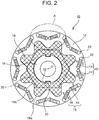
- FIG. 2 is a view of the rotor 10 as viewed in a Y direction. In FIG. 2 , only an outline of a nut 20 is illustrated by a two-dot chain line.
- FIG. 3 is an enlarged view of a part A of FIG. 2 .
- This rotor 10 is used for a rotary electric machine, for example, a three-phase synchronous rotary electric machine installed in an electric vehicle or the like, as a drive source.
- the rotor 10 includes a rotor core 12, permanent magnets 14 embedded in the rotor core 12, a rotary shaft 16 fixedly attached to the rotor core 12, and a washer 18 and a nut 20 applying an axial force to the rotor core 12.
- the rotor core 12 is a generally annular shaped body having a shaft hole at a center thereof.
- the rotor core 12 is formed by stacking a plurality of electromagnetic steel plates (such as silicon steel plates) in the axial direction.
- the rotor core 12 is formed with a plurality of magnet holes 22 in the vicinity of an outer circumferential end of the rotor core 12, and the plurality of magnet holes 22 are arranged at intervals from one another in the circumferential direction.
- Each magnet hole 22 extends through the rotor core 12, in the axial direction, and a permanent magnet 14 composing a magnetic pole of the rotor 10 is disposed inside each magnet hole 22.
- the permanent magnets 14 are disposed in a V-shape arrangement. That is, a single magnetic pole 15 is composed by a pair of permanent magnets 14 arranged in a V-shape opening radially outward.
- the rotor 10 has sixteen permanent magnets 14 composing eight magnetic poles 15.
- Each permanent magnet 14 has a generally rectangular shaped cross section, and is magnetized in a short-side direction of the rectangular shaped cross section (substantially a rotor-radial direction).
- permanent magnets 14 composing S-magnetic poles are arranged such that S poles are located radially outward, and permanent magnets 14 composing N-magnetic poles are arranged such that N poles are located radially outward.
- the magnet holes 22 are also disposed in a V-shape arrangement so as to receive the permanent magnets 14 disposed in a V-shape arrangement. That is, the rotor core 12 is provided with multiple pairs (eight pairs in the illustrated example) of the magnet holes 22 at equal intervals from one another in the circumferential direction, each pair of the magnet holes 22 being arranged in a V-shape opening radially outward.
- Each magnet hole 22 has a generally rectangular shape, a long-side dimension of which is greater than that of each permanent magnet 14.
- voids are formed on both sides in the long-side direction of this permanent magnet 14.
- Such a void is called a flux barrier, and functions as a magnetic resisting portion so as to regulate magnetic characteristics of the rotor core 12.
- each bridge 24 is configured as a part of the rotor core 12, but the bridge 24 may be composed by using a member different from the stacked steel plates composing the rotor core 12.
- a through-hole continued in a single line may be formed in a generally V-shape, and a bridge member 25 as indicated by a two-dot line in FIG. 4 may be arranged in a valley portion of this V-shaped through-hole.
- a material of the bridge member 25 is not limited to a specific one, but it is preferable to use a non-magnetic one for this material.
- the rotary shaft 16 is mounted into the shaft hole of the rotor core 12, and is fixedly attached to the rotor core 12.
- the rotary shaft 16 is rotatably supported via a not-illustrated bearing, and integrally rotates with the rotor core 12.
- a flange 26 protruding radially outward is formed in an intermediate portion of the rotary shaft 16, possibly in the middle of the rotary shaft 16. The rotor core 12 through which the rotary shaft 16 is inserted is pushed against this flange 26.
- Bold lines in FIG. 1 indicate a position where the male screw is formed.
- the nut 20 is screwed onto this male screw.
- the rotary shaft 16 is illustrated in a hollow cylindrical shape, but the configuration of the rotary shaft 16 is not limited to a specific one as far as the rotary shaft 16 is concentric to the rotor core 12, and has an outer circumferential surface having a substantially circular cross section.
- the rotary shaft 16 may be as a solid round bar shape, or may be formed with a coolant flow passage thereinside.
- the rotary shaft 16 is inserted through the washer 18 from its end portion opposite to the flange 26 so that the washer 18 comes into contact with an axial end surface of the rotor core 12.
- the nut 20 is mounted onto the rotary shaft 16 from its end portion opposite to the flange 26 so as to be screwed with the male screw formed on the rotary shaft 16. By being fastened with this nut 20, the rotor core 12 is held between the washer 18 and the flange 26 so as to restrict its movement in the axial direction, and also receive a compression force (axial force) in the axial direction.
- the washer 18 is configured to have a special shape. This will be described in comparison with the related art.
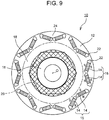
- FIG. 9 is an example of the rotor 10 of the related art.
- the washer 18 is configured to have an annular shape the diameter of which is substantially the same as that of the nut 20, so that the washer 18 is in contact with the rotor core 12 by a radially inward area one third as large as the rotor core 12.
- the washer 18 does not cover the permanent magnet 14.
- the outer diameter of the washer 18 in an annular shape is enlarged to the vicinity of the inner circumferential ends of the magnet holes 22.
- the washer 18 is configured to have a special shape. That is, as shown in FIG. 2 and FIG. 3 , the outer circumferential shape of the washer 18 of this example is located further inward radially than the magnet holes 22, and a distance from a rotation center O to the outer circumferential end of the washer 18 periodically varies in the circumferential direction so as to have a shape with recesses and projections.
- the washer 18 has such a shape that a distance D1 from the outer circumferential end of the washer 18 to each bridge 24 is not less than a distance D2 from the outer circumferential end of the washer 18 to each magnet hole 22.
- each of the distance D1 and the distance D2 means a minimum distance.
- the “distance D2 from the outer circumferential end of the washer 18 to each magnet hole 22” means a width of the space between the outer circumferential end of the washer 18 to this magnet hole 22, at a position where the width of the space is the smallest.
- the “distance D1 from the outer circumferential end of the washer 18 to each bridge 24" means a width of the space between the outer circumferential end of the washer 18 and this bridge 24, at a position where the width of the space is the smallest.
- the shape of the washer 18 is more specifically described.
- the outer circumferential shape of the washer 18 is a generally flower-like shape or a generally gear-like shape having round corners.
- the generally flower-like shape and the generally gear-like shape each include projecting portions 18a, each in an arc shape projecting radially outward, and recessed portions 18b, each in an arc shape recessed radially inward, the projecting portions 18a and the recessed portions 18b being arranged alternately with each other in the circumferential direction.
- Such a variation period of the recesses and projections of the outer circumferential shape of the washer 18 coincides with an arrangement pitch of the magnetic poles 15, or an arrangement pitch of the bridges 24 as the reduced-rigidity portions.
- there are eight magnetic poles 15 and eight bridges 24, and each arrangement pitch thereof is 360/8 45°; therefore, the projections and the recesses of the outer circumferential shape of the washer 18 vary with a period of 45°.
- the washer 18 is disposed such that a center point (hereinafter, referred to as a "recess point 19") of each recessed portion 18b, where a distance from the rotation center to the outer circumferential end of the washer 18 is minimized, is located in the same angular position (phase) as that of each bridge 24.
- the washer 18 is disposed such that each recess point 19 and each bridge 24 are aligned in a straight line in the radial direction. More specifically, the washer 18 is disposed such that a recess point 19 and a closest bridge 24 thereto are disposed on a same radius of the rotor core 12.
- the outer circumferential shape of the washer 18 is similar to a shape formed by connecting lines obtained by offsetting inner circumferential ends of the magnet holes 22 disposed in a generally V-shape arrangement toward a radially inward direction.
- the washer 18 has an opening angle ⁇ 1 at a position corresponding to the V-shape or the recessed portion 18b that is smaller than an opening angle ⁇ 2 at this position of each magnet hole 22, so that the washer 18 has a V-shape deeper radially inward than that of the magnet hole 22.
- the distance D1 from the outer circumferential end of the washer 18 to the bridge 24 is not less than a distance D2 from the outer circumferential end of the washer 18 to the magnet hole 22.
- each portion of the washer 18 that is circumferentially offset from the bridge 24 extends further outward radially than in the rotor 10 of the related art, and thus an axial force can be applied in a wide range of the rotor core 12. Accordingly, according to the washer 18 of the present example, it is possible to prevent local deterioration of the rotor core 12, or the like, while maintaining a sufficient axial force applied to the rotor core 12.
- the washer 18 is key-engaged with the rotary shaft 16. Specifically, an inner circumferential surface of the washer 18 is provided with key-projections 30 projecting radially inward, and the outer circumferential surface of the rotary shaft 16 is provided with key-grooves 32 receiving the key-projections 30.
- the washer 18 is assembled to the rotary shaft 16 such that the key-projections 30 are fitted into the key-grooves 32, to thereby constrain the angular position of the washer 18 relative to the rotor core 12 in a preferable manner.
- the washer 18 is provided with the key-projections 30, and the rotary shaft 16 is provided with the key-grooves 32, but this combination may be inverted.
- the rotary shaft 16 may be provided with the key-projections, and the washer 18 may be provided with the key-grooves.
- the number of the key-grooves 32 and the number of the key-projections 30 may appropriately be changed.
- FIG. 5 is a view showing one example of another rotor 10.
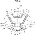
- FIG. 6 is an enlarged view of a part B of FIG. 5 .
- each single magnetic pole 15 is composed by three permanent magnets 14a, 14b arranged in an inverted triangle shape (subscripts are omitted when the permanent magnets 14a, 14b of two types are not distinguished from each other. This is the same in the magnet holes described later). That is, each single magnetic pole 15 is composed by a pair of the permanent magnets 14a arranged in a V-shape opening radially outward and one permanent magnet 14b disposed between respective outer circumferential ends of the pair of the permanent magnets 14a.
- the rotor core 12 is formed with the magnet holes 22 for receiving the permanent magnets 14.
- Each pair of magnet holes 22a is arranged in a V-shape opening radially outward. Note that these two magnet holes 22a are not adjacent to each other in the circumferential direction, but there is an intermediate hole 28 between respective inner circumferential ends of the two magnet holes 22a.
- Each intermediate hole 28 is a through-hole extending through the rotor core 12 in the axial direction. This intermediate hole 28 functions as a magnetic resisting portion, and by providing the intermediate hole 28, magnetic flux flows can be regulated.
- the bridge 24, forming a narrow space portion where rigidity of the rotor core 12 is locally reduced, is formed between each intermediate hole 28 and each magnet hole 22a.
- each void hole 29 is a through-hole extending through the rotor core 12 in the axial direction, and functions as a magnetic resisting portion. This void hole 29 is also provided so as to regulate the magnetic flux flows.
- the washer 18 is disposed on the axial end surface of the rotor core 12, and the washer 18 is held forcibly against the rotor core 12 with a fastening force by the nut 20 (not illustrated in FIG. 5 and FIG. 6 ).
- the outer circumferential shape of the washer 18 of this example is located further inward radially than the magnet holes 22, and the distance thereof from the rotation center O to the outer circumferential end periodically varies in the circumferential direction so as to have a shape with recesses and projections.
- the washer 18 has such a shape that a distance D1 from the outer circumferential end of the washer 18 to each bridge 24 is not less, or preferably greater, than a distance D2 from the outer circumferential end of the washer 18 to each magnet hole 22.
- the outer circumferential shape of the washer 18 is a generally flower-like shape or a generally gear-like shape having round corners.
- the generally flower-like shape and the generally gear-like shape each include the projecting portions 18a, each in an arc shape projecting radially outward, and the recessed portions 18b, each in an arc shape recessed radially inward, the projecting portions 18a and the recessed portions 18b being arranged alternately with each other in the circumferential direction.
- the variation period of the recesses and projections of the outer circumferential shape of the washer 18 coincides with the arrangement pitch of the magnetic poles 15.
- each recess point 19 where a distance from the rotation center to the outer circumferential end of the washer 18 is minimized, is located in the same phase as that of the circumferential center of the intermediate hole 28.
- the washer 18 is disposed such that each recess point 19 and the circumferential center of each intermediate hole 28 are aligned in a straight line in the radial direction.
- each recessed portion 18b is formed in a generally arc shape recessed radially inward in the examples of FIG. 5 and FIG. 6 , but this recessed portion 18b may be a straight shape extending in the generally circumferential direction, as shown in FIG. 7 .
- the distance D1 from the outer circumferential end of the washer 18 to the bridge 24 can be greater, to thus further limit stress concentration on each bridge 24.
- FIG. 8 is a view showing one example of another rotor 10.
- each single magnetic pole 15 is composed by a single permanent magnet 14 that has a long cross-sectional dimension in the generally circumferential direction.
- the rotor 10 includes sixteen magnetic poles 15 and sixteen permanent magnets 14.
- the rotor core 12 is formed with the magnet holes 22 for receiving these permanent magnets 14.
- Each magnet hole 22 has a rectangular shaped cross-section, possibly with rounded corners, that is long in the generally circumferential direction, and a long side dimension is greater than a long side dimension of the permanent magnet 14.
- a space portion 36 having a thin width is formed between each two magnet holes 22 adjacent to each other in the circumferential direction. It can be said that this space portion 36 is a reduced-rigidity portion where rigidity of the rotor core 12 is locally reduced, as with the above described bridge 24.
- the washer 18 in tight contact with this rotor core 12 has an outer circumferential shape located further inward radially than the magnet holes 22, and having recesses and projections in which the distance from the rotation center O to the outer circumferential end periodically varies in the circumferential direction.
- the washer 18 has such a shape that the distance D1 from the outer circumferential end of the washer 18 to each space portion 36 is not less than the distance D2 from the outer circumferential end of the washer 18 to each magnet hole 22.
- the outer circumferential shape of the washer 18 is a generally flower-like shape or a generally star-like shape having round corners.
- the generally flower-like shape and the generally star-like shape each include projecting portions 18a, each in an arc shape projecting radially outward, and recessed portions 18b, each in an arc shape recessed radially inward, the projecting portions 18a and the recessed portions 18b being arranged alternately with each other in the circumferential direction.
- the variation period of the recesses and projections of the outer circumferential shape of the washer 18 coincides with the arrangement pitch of the magnetic poles 15.
- the washer 18 is disposed such that the circumferential center point of each recessed portion 18b (hereinafter, referred to as a "recess point 19"), where the distance from the rotation center O to the outer circumferential end of the washer 18 is minimized, is located in the same phase as that of the space portion 36.
- the washer 18 is disposed such that each recess point 19 and the space portion 36 are aligned in a straight line in the radial direction.
- the rotor 10 disclosed in the present specification it is possible to reduce stress applied onto the reduced-rigidity portions.
- the configuration disclosed in the present specification is an example, and as far as the distance from the outer circumferential end of the washer to each reduced-rigidity portion is not less than the distance from the outer circumferential end of the washer to each magnet hole, the other configurations may appropriately be changed.
- the washer 18 is formed in a generally gear-like shape having all corners round, but may be formed in a generally gear-like shape having sharp corners.
Landscapes
- Engineering & Computer Science (AREA)
- Power Engineering (AREA)
- Manufacturing & Machinery (AREA)
- Iron Core Of Rotating Electric Machines (AREA)
- Permanent Field Magnets Of Synchronous Machinery (AREA)
Abstract
Description
- The present specification discloses a rotor for a rotary electric machine with a washer interposed between a nut screwed onto a rotary shaft and a rotor core.
- In general, a rotor core is composed by stacking a plurality of magnetic steel plates. It has been conventionally proposed that such a rotor core is fastened by a nut screwed onto a rotary shaft so as to apply a compression force in the axial direction to the rotor core. Further, it has also been proposed that a generally annular washer is interposed between this nut and the rotor core. By interposing the washer therebetween, a fastening force by the nut is applied to the rotor core via this washer. Normally, the rotary shaft is inserted through the washer, and an outer circumferential end of the washer is located further inward radially than the magnets so as to prevent magnetic short-circuit.
- A rotor core has been formed with a plurality of magnet holes extending through the rotor core in the axial direction so as to insert magnets into these magnet holes. In addition to the magnet holes, the rotor core is also formed with through-holes used for regulating magnetic flux flows and forming magnetic resistance, in some cases. Due to these through-holes, there are reduced-rigidity portions where rigidity of the rotor core is locally reduced. For example, in order to arrange two magnets in a V-shape, two magnet holes in a V-shape are formed in the rotor core. It can be said that a relatively narrow space between these two magnet holes, that is, a portion referred to as a bridge, is a reduced-rigidity portion where rigidity of the rotor core is locally reduced. Japanese Patent Application Publication No.
2015-56911 - When a washer is held forcibly against an axial end surface of the rotor core, a stress is generated inside the rotor core due to this pushing force (axial force). If a position pushed by the washer is close to reduced-rigidity portions, a stress is concentrated at these reduced-rigidity portions, so that deterioration or breakage is likely to occur at the reduced-rigidity portions. Hence, conventionally, a generally annular washer is configured to have a smaller diameter so as not to set its outer circumferential end too close to the reduced-rigidity portions. Unfortunately, when the washer is configured to have a smaller diameter, a contact area between the washer and the rotor core is reduced, and thus there is such a concern that a sufficient axial force cannot be applied to the entire rotor core.
- To cope with this, the present invention provides a rotor for a rotary electric machine capable of reducing stress applied to reduced-rigidity portions, while maintaining a sufficient axial force.
- An exemplary aspect of the present disclosure is a rotor for a rotary electric machine. The rotor for a rotary electric machine includes: a rotor core having a generally annular shape, the rotor core having a shaft hole at a center, the rotor core having a plurality of magnet holes arranged in a circumferential direction, the rotor core including at least one reduced-rigidity portion where rigidity of the rotor core is locally reduced; a plurality of magnets disposed in the respective magnet holes; a rotary shaft mounted in the shaft hole and fixedly attached to the rotor core; a washer contacting at least one end surface, in an axial direction, of the rotor core; and a nut screwed on the rotary shaft such that the washer is held forcibly against the rotor core. An outer circumferential end of the washer is disposed further inward radially than the magnet holes. The washer has an outer circumferential shape with recesses and projections in which a distance from a rotation center to the outer circumferential end of the washer periodically varies. A distance from the outer circumferential end of the washer to each reduced-rigidity portion is greater than a distance from the outer circumferential end of the washer to a magnet hole closest to said reduced-rigidity portion.
- The washer may be tightly or directly contacting the axial end surface of the rotor core, e.g. so as to induce stresses therein. By configuring the washer to have an outer circumferential shape with recesses and projections in which the distance from the rotation center to the outer circumferential end periodically varies, and by setting a distance from the outer circumferential end of the washer to each reduced-rigidity portion to be greater than the distance from the outer circumferential end of the washer to a magnet hole closest to said reduced-rigidity portion, and preferably to each magnet hole, it is possible to apply an axial force in a wide range of the rotor core, while limiting stress concentration onto the reduced-rigidity portions. As a result, it is possible to reduce stress applied to the reduced-rigidity portions, while maintaining a sufficient axial force.
- The rotor core may include a plurality of pairs of magnet holes in the circumferential direction, each pair of the magnet holes arranged in a V-shape opening radially outward. The at least one reduced-rigidity portion may include at least one bridge, wherein each bridge forms a space provided between the magnet holes of each pair of magnet holes. The space may be narrower than a space between the magnet holes of two adjacent pairs of magnet holes.
- With such a configuration, also in the rotor including the magnets disposed in a V-shaped arrangement, it is possible to reduce stress applied to the reduced-rigidity portions, while maintaining a sufficient axial force.
- Each magnet hole may be elongated in the circumferential direction, and the reduced-rigidity portion may be the space between the magnet holes adjacent to each other in the circumferential direction.
- With such a configuration, also in the rotor including the magnets disposed in an I-shaped arrangement, it is possible to reduce stress applied to the reduced-rigidity portions, while maintaining a sufficient axial force.
- The washer may be disposed such that at the same angular position as an angular position of each reduced-rigidity portion, a distance from the rotation center to the outer circumferential end is minimized.
- As a consequence, the distance from the outer circumferential end of the washer to each reduced-rigidity portion can be easily greater, to thus more efficiently limit stress concentration on the reduced-rigidity portions.
- The rotor core may have a plurality of sets of through-holes in the circumferential direction, each of the sets of through-holes including: a pair of said magnet holes arranged circumferentially adjacent to each other in a V-shape opening radially outward; and an intermediate hole being disposed between the magnet holes of said pair. Each reduced-rigidity portion may include a bridge, wherein the bridge forms a space between each magnet hole and each intermediate hole of one of the sets. The space may be narrower than a space between the magnet holes of two adjacent pairs of magnet holes.
- With such a configuration, even in the rotor formed with the intermediate holes, it is possible to reduce stress applied to the reduced-rigidity portions, while maintaining a sufficient axial force.
- The washer may be disposed such that at the same angular position as an angular position of the intermediate hole, the distance from the rotation center to the outer circumferential end is minimized.
- As a consequence, the distance from the outer circumferential end of the washer to each reduced-rigidity portion can easily be greater, to thus more efficiently limit stress concentration on the reduced-rigidity portions.
- The outer circumferential shape of the washer may be a gear-like shape having round corners.
- The outer circumferential shape of the washer does not have sharp corners, to thus prevent overconcentration of stress at a single local position.
- One of an inner circumferential surface of the washer and an outer circumferential surface of the rotary shaft may include a key-projection projecting to the other circumferential surface, and the other of the inner circumferential surface of the washer and the outer circumferential surface of the rotary shaft may have a key-groove configured to receive the key-projection.
- With such a configuration, it is possible to effectively constrain the angular position of the washer relative to the rotor core.
- According to the above configuration, the washer has an outer circumferential shape with recesses and projections in which the distance from the rotation center to the outer circumferential end periodically varies, and the distance from the outer circumferential end of the washer to each reduced-rigidity portion is set to be greater than the distance from the outer circumferential end of the washer to each magnet hole. It is thus possible to apply a wide range of axial force on the rotor core, while limiting or preventing stress concentration onto the reduced-rigidity portions. Accordingly, it is possible to reduce stress applied to the reduced-rigidity portions, while maintaining a sufficient axial force.
- Features, advantages, and technical and industrial significance of exemplary embodiments of the invention will be described below with reference to the accompanying drawings, in which like numerals denote like elements, and wherein:
-
FIG. 1 is a schematic longitudinal sectional view of a rotor; -
FIG. 2 is a view of the rotor as viewed from a Y direction; -
FIG. 3 is an enlarged view of a part A ofFIG. 2 ; -
FIG. 4 is a view showing another configuration of a bridge; -
FIG. 5 is a view showing one example of another rotor; -
FIG. 6 is an enlarged view of a part B ofFIG. 5 ; -
FIG. 7 is a view showing one example of another rotor; -
FIG. 8 is a view showing one example of another rotor; and -
FIG. 9 is a view showing one example of a rotor of related art. - Hereinafter, a configuration of a
rotor 10 for a rotary electric machine will be described with reference to drawings.FIG. 1 is a schematic longitudinal sectional view of therotor 10.FIG. 2 is a view of therotor 10 as viewed in a Y direction. InFIG. 2 , only an outline of anut 20 is illustrated by a two-dot chain line.FIG. 3 is an enlarged view of a part A ofFIG. 2 . - This
rotor 10 is used for a rotary electric machine, for example, a three-phase synchronous rotary electric machine installed in an electric vehicle or the like, as a drive source. Therotor 10 includes arotor core 12,permanent magnets 14 embedded in therotor core 12, arotary shaft 16 fixedly attached to therotor core 12, and awasher 18 and anut 20 applying an axial force to therotor core 12. - The
rotor core 12 is a generally annular shaped body having a shaft hole at a center thereof. Therotor core 12 is formed by stacking a plurality of electromagnetic steel plates (such as silicon steel plates) in the axial direction. Therotor core 12 is formed with a plurality of magnet holes 22 in the vicinity of an outer circumferential end of therotor core 12, and the plurality of magnet holes 22 are arranged at intervals from one another in the circumferential direction. Eachmagnet hole 22 extends through therotor core 12, in the axial direction, and apermanent magnet 14 composing a magnetic pole of therotor 10 is disposed inside eachmagnet hole 22. - In this example, the
permanent magnets 14 are disposed in a V-shape arrangement. That is, a singlemagnetic pole 15 is composed by a pair ofpermanent magnets 14 arranged in a V-shape opening radially outward. In an example ofFIG. 2 , therotor 10 has sixteenpermanent magnets 14 composing eightmagnetic poles 15. Eachpermanent magnet 14 has a generally rectangular shaped cross section, and is magnetized in a short-side direction of the rectangular shaped cross section (substantially a rotor-radial direction). Of thepermanent magnets 14,permanent magnets 14 composing S-magnetic poles are arranged such that S poles are located radially outward, andpermanent magnets 14 composing N-magnetic poles are arranged such that N poles are located radially outward. - The magnet holes 22 are also disposed in a V-shape arrangement so as to receive the
permanent magnets 14 disposed in a V-shape arrangement. That is, therotor core 12 is provided with multiple pairs (eight pairs in the illustrated example) of the magnet holes 22 at equal intervals from one another in the circumferential direction, each pair of the magnet holes 22 being arranged in a V-shape opening radially outward. Eachmagnet hole 22 has a generally rectangular shape, a long-side dimension of which is greater than that of eachpermanent magnet 14. Hence, when eachpermanent magnet 14 is inserted into eachcorresponding magnet hole 22, voids are formed on both sides in the long-side direction of thispermanent magnet 14. Such a void is called a flux barrier, and functions as a magnetic resisting portion so as to regulate magnetic characteristics of therotor core 12. - Two magnet holes 22 belonging to the same magnetic pole are close to each other in the circumferential direction, and a
bridge 24 that is a narrow space portion is formed between the both magnet holes 22. It can be said that thisbridge 24 is a reduced-rigidity portion where rigidity of therotor core 12 is locally reduced. Stress is likely to be concentrated in such bridges 24 (reduced-rigidity portions), so that deterioration or breakage thereof is likely. Hence, in order to reduce stress concentration in thebridges 24, thewasher 18 is configured to be in a special shape, and this will be described later. - In this example, each
bridge 24 is configured as a part of therotor core 12, but thebridge 24 may be composed by using a member different from the stacked steel plates composing therotor core 12. For example, as shown inFIG. 4 , a through-hole continued in a single line may be formed in a generally V-shape, and abridge member 25 as indicated by a two-dot line inFIG. 4 may be arranged in a valley portion of this V-shaped through-hole. In this case, a material of thebridge member 25 is not limited to a specific one, but it is preferable to use a non-magnetic one for this material. - The
rotary shaft 16 is mounted into the shaft hole of therotor core 12, and is fixedly attached to therotor core 12. Therotary shaft 16 is rotatably supported via a not-illustrated bearing, and integrally rotates with therotor core 12. Aflange 26 protruding radially outward is formed in an intermediate portion of therotary shaft 16, possibly in the middle of therotary shaft 16. Therotor core 12 through which therotary shaft 16 is inserted is pushed against thisflange 26. - An outer circumferential surface of the
rotary shaft 16, which is located opposite to theflange 26 with respect to therotor core 12, is formed with a male screw. Bold lines inFIG. 1 indicate a position where the male screw is formed. As described later, thenut 20 is screwed onto this male screw. In this drawing, therotary shaft 16 is illustrated in a hollow cylindrical shape, but the configuration of therotary shaft 16 is not limited to a specific one as far as therotary shaft 16 is concentric to therotor core 12, and has an outer circumferential surface having a substantially circular cross section. Hence, therotary shaft 16 may be as a solid round bar shape, or may be formed with a coolant flow passage thereinside. - The
washer 18 and thenut 20, together with theflange 26, restrict movement of therotor core 12 in the axial direction, and also applies a compression force to therotor core 12 in the axial direction. Therotary shaft 16 is inserted through thewasher 18 from its end portion opposite to theflange 26 so that thewasher 18 comes into contact with an axial end surface of therotor core 12. Thenut 20 is mounted onto therotary shaft 16 from its end portion opposite to theflange 26 so as to be screwed with the male screw formed on therotary shaft 16. By being fastened with thisnut 20, therotor core 12 is held between thewasher 18 and theflange 26 so as to restrict its movement in the axial direction, and also receive a compression force (axial force) in the axial direction. - Here, in the
rotor 10 disclosed in the present specification, for the purpose of preventing local deterioration of therotor core 12, or the like while sufficiently maintaining the axial force applied to therotor core 12, thewasher 18 is configured to have a special shape. This will be described in comparison with the related art.FIG. 9 is an example of therotor 10 of the related art. - When the axial force applied to the
rotor core 12 decreases, a fixing force for therotor core 12 naturally decreases. When the axial force decreases, axial gaps between the electromagnetic steel plates composing therotor core 12 are enlarged, so that coolant leaks through the gaps. Hence, it is desired to apply a sufficient axial force to therotor core 12. - In order to enhance the axial force applied to the
rotor core 12, naturally, a fastening force by thenut 20 may be increased. However, in the configuration of the related art, thewasher 18 is configured to have an annular shape the diameter of which is substantially the same as that of thenut 20, so that thewasher 18 is in contact with therotor core 12 by a radially inward area one third as large as therotor core 12. Hence, if the fastening force by thenut 20 is increased, a great fastening force (axial force) is applied to only this radially inward area one third as large as therotor core 12; consequently, it is difficult to apply a sufficient axial force to theentire rotor core 12. - To cope with this, it is natural to consider to increase the area of the
washer 18. However, in light of prevention of magnetic short-circuit and heat radiation of thepermanent magnet 14, and others, it is preferable that thewasher 18 does not cover thepermanent magnet 14. To cope with this, for example, it can be considered that the outer diameter of thewasher 18 in an annular shape is enlarged to the vicinity of the inner circumferential ends of the magnet holes 22. With such a configuration, a fastening force by thenut 20 can be distributed in a wider area, and thus it is possible to apply a sufficient axial force to theentire rotor core 12. - However, if the outer diameter of the
annular washer 18 is simply enlarged, force is applied to the vicinities of thebridges 24 where rigidity of the rotor core is locally reduced. In this case, a stress caused in therotor core 12 by applying the fastening force is likely to be concentrated on thebridges 24, which have reduced rigidities. Consequently, other problems, such as deterioration and breakage of thebridges 24, are caused. - To cope with this, in the
rotor 10 disclosed in the present specification, thewasher 18 is configured to have a special shape. That is, as shown inFIG. 2 andFIG. 3 , the outer circumferential shape of thewasher 18 of this example is located further inward radially than the magnet holes 22, and a distance from a rotation center O to the outer circumferential end of thewasher 18 periodically varies in the circumferential direction so as to have a shape with recesses and projections. In addition, as shown inFIG. 3 , thewasher 18 has such a shape that a distance D1 from the outer circumferential end of thewasher 18 to eachbridge 24 is not less than a distance D2 from the outer circumferential end of thewasher 18 to eachmagnet hole 22. Here, each of the distance D1 and the distance D2 means a minimum distance. For example, the "distance D2 from the outer circumferential end of thewasher 18 to eachmagnet hole 22" means a width of the space between the outer circumferential end of thewasher 18 to thismagnet hole 22, at a position where the width of the space is the smallest. Similarly, the "distance D1 from the outer circumferential end of thewasher 18 to eachbridge 24" means a width of the space between the outer circumferential end of thewasher 18 and thisbridge 24, at a position where the width of the space is the smallest. - The shape of the
washer 18 is more specifically described. The outer circumferential shape of thewasher 18 is a generally flower-like shape or a generally gear-like shape having round corners. The generally flower-like shape and the generally gear-like shape each include projectingportions 18a, each in an arc shape projecting radially outward, and recessedportions 18b, each in an arc shape recessed radially inward, the projectingportions 18a and the recessedportions 18b being arranged alternately with each other in the circumferential direction. Such a variation period of the recesses and projections of the outer circumferential shape of thewasher 18 coincides with an arrangement pitch of themagnetic poles 15, or an arrangement pitch of thebridges 24 as the reduced-rigidity portions. In the present example, there are eightmagnetic poles 15 and eightbridges 24, and each arrangement pitch thereof is 360/8=45°; therefore, the projections and the recesses of the outer circumferential shape of thewasher 18 vary with a period of 45°. - In addition, the
washer 18 is disposed such that a center point (hereinafter, referred to as a "recess point 19") of each recessedportion 18b, where a distance from the rotation center to the outer circumferential end of thewasher 18 is minimized, is located in the same angular position (phase) as that of eachbridge 24. In other words, thewasher 18 is disposed such that eachrecess point 19 and eachbridge 24 are aligned in a straight line in the radial direction. More specifically, thewasher 18 is disposed such that arecess point 19 and aclosest bridge 24 thereto are disposed on a same radius of therotor core 12. - Hence, the outer circumferential shape of the
washer 18 is similar to a shape formed by connecting lines obtained by offsetting inner circumferential ends of the magnet holes 22 disposed in a generally V-shape arrangement toward a radially inward direction. However, thewasher 18 has an opening angle α1 at a position corresponding to the V-shape or the recessedportion 18b that is smaller than an opening angle α2 at this position of eachmagnet hole 22, so that thewasher 18 has a V-shape deeper radially inward than that of themagnet hole 22. As a result, the distance D1 from the outer circumferential end of thewasher 18 to thebridge 24 is not less than a distance D2 from the outer circumferential end of thewasher 18 to themagnet hole 22. - In this manner, since the distance D1 from the outer circumferential end of the
washer 18 to eachbridge 24 is increased, an axial force is hardly applied to the vicinity of eachbridge 24, where rigidity of the rotor core is locally reduced, thus limiting or preventing stress concentration onto thebridge 24. Accordingly, it is possible to effectively limit or prevent deterioration and damages of thebridges 24. In the meantime, each portion of thewasher 18 that is circumferentially offset from thebridge 24 extends further outward radially than in therotor 10 of the related art, and thus an axial force can be applied in a wide range of therotor core 12. Accordingly, according to thewasher 18 of the present example, it is possible to prevent local deterioration of therotor core 12, or the like, while maintaining a sufficient axial force applied to therotor core 12. - In order to prevent or limit the stress concentration on the
bridges 24, it is desirable to align the phase of eachrecess point 19 of thewasher 18 with the phase of eachbridge 24. Hence, in therotor 10 disclosed in the present specification, in order to align the phase of thewasher 18 with the phase of therotor core 12, thewasher 18 is key-engaged with therotary shaft 16. Specifically, an inner circumferential surface of thewasher 18 is provided with key-projections 30 projecting radially inward, and the outer circumferential surface of therotary shaft 16 is provided with key-grooves 32 receiving the key-projections 30. Thewasher 18 is assembled to therotary shaft 16 such that the key-projections 30 are fitted into the key-grooves 32, to thereby constrain the angular position of thewasher 18 relative to therotor core 12 in a preferable manner. - In the present example, the
washer 18 is provided with the key-projections 30, and therotary shaft 16 is provided with the key-grooves 32, but this combination may be inverted. This means that therotary shaft 16 may be provided with the key-projections, and thewasher 18 may be provided with the key-grooves. The number of the key-grooves 32 and the number of the key-projections 30 may appropriately be changed. -
FIG. 5 is a view showing one example of anotherrotor 10.FIG. 6 is an enlarged view of a part B ofFIG. 5 . In thisrotor 10, each singlemagnetic pole 15 is composed by threepermanent magnets permanent magnets magnetic pole 15 is composed by a pair of thepermanent magnets 14a arranged in a V-shape opening radially outward and onepermanent magnet 14b disposed between respective outer circumferential ends of the pair of thepermanent magnets 14a. - The
rotor core 12 is formed with the magnet holes 22 for receiving thepermanent magnets 14. Each pair ofmagnet holes 22a is arranged in a V-shape opening radially outward. Note that these twomagnet holes 22a are not adjacent to each other in the circumferential direction, but there is anintermediate hole 28 between respective inner circumferential ends of the twomagnet holes 22a. Eachintermediate hole 28 is a through-hole extending through therotor core 12 in the axial direction. Thisintermediate hole 28 functions as a magnetic resisting portion, and by providing theintermediate hole 28, magnetic flux flows can be regulated. Here, as apparent fromFIG. 6 , thebridge 24, forming a narrow space portion where rigidity of therotor core 12 is locally reduced, is formed between eachintermediate hole 28 and eachmagnet hole 22a. - In addition, a
magnet hole 22b extending in the circumferential direction is formed between respective outer circumferential ends of the twomagnet holes 22a of every pair. A pair of void holes 29 is formed circumferentially around eachmagnet hole 22b. As similar to theintermediate hole 28, eachvoid hole 29 is a through-hole extending through therotor core 12 in the axial direction, and functions as a magnetic resisting portion. Thisvoid hole 29 is also provided so as to regulate the magnetic flux flows. - In examples shown in
FIG. 5 andFIG. 6 , thewasher 18 is disposed on the axial end surface of therotor core 12, and thewasher 18 is held forcibly against therotor core 12 with a fastening force by the nut 20 (not illustrated inFIG. 5 andFIG. 6 ). As similar to the example shown inFIG. 2 , the outer circumferential shape of thewasher 18 of this example is located further inward radially than the magnet holes 22, and the distance thereof from the rotation center O to the outer circumferential end periodically varies in the circumferential direction so as to have a shape with recesses and projections. In addition, as shown inFIG. 6 , thewasher 18 has such a shape that a distance D1 from the outer circumferential end of thewasher 18 to eachbridge 24 is not less, or preferably greater, than a distance D2 from the outer circumferential end of thewasher 18 to eachmagnet hole 22. - To be more specific, the outer circumferential shape of the
washer 18 is a generally flower-like shape or a generally gear-like shape having round corners. The generally flower-like shape and the generally gear-like shape each include the projectingportions 18a, each in an arc shape projecting radially outward, and the recessedportions 18b, each in an arc shape recessed radially inward, the projectingportions 18a and the recessedportions 18b being arranged alternately with each other in the circumferential direction. The variation period of the recesses and projections of the outer circumferential shape of thewasher 18 coincides with the arrangement pitch of themagnetic poles 15. - In addition, the
washer 18 is disposed such that eachrecess point 19, where a distance from the rotation center to the outer circumferential end of thewasher 18 is minimized, is located in the same phase as that of the circumferential center of theintermediate hole 28. In other words, thewasher 18 is disposed such that eachrecess point 19 and the circumferential center of eachintermediate hole 28 are aligned in a straight line in the radial direction. With such a configuration, it is possible to reduce the stress concentration on thebridges 24, and it is also possible to apply an axial force in a wide range of therotor core 12. - Note that each recessed
portion 18b is formed in a generally arc shape recessed radially inward in the examples ofFIG. 5 andFIG. 6 , but this recessedportion 18b may be a straight shape extending in the generally circumferential direction, as shown inFIG. 7 . With such a configuration, as compared to the cases ofFIG. 5 andFIG. 6 , the distance D1 from the outer circumferential end of thewasher 18 to thebridge 24 can be greater, to thus further limit stress concentration on eachbridge 24. -
FIG. 8 is a view showing one example of anotherrotor 10. In thisrotor 10, each singlemagnetic pole 15 is composed by a singlepermanent magnet 14 that has a long cross-sectional dimension in the generally circumferential direction. In the example ofFIG. 8 , therotor 10 includes sixteenmagnetic poles 15 and sixteenpermanent magnets 14. - The
rotor core 12 is formed with the magnet holes 22 for receiving thesepermanent magnets 14. Eachmagnet hole 22 has a rectangular shaped cross-section, possibly with rounded corners, that is long in the generally circumferential direction, and a long side dimension is greater than a long side dimension of thepermanent magnet 14. Aspace portion 36 having a thin width is formed between each twomagnet holes 22 adjacent to each other in the circumferential direction. It can be said that thisspace portion 36 is a reduced-rigidity portion where rigidity of therotor core 12 is locally reduced, as with the above describedbridge 24. - As with the
washer 18 shown inFIG. 2 , thewasher 18 in tight contact with thisrotor core 12 has an outer circumferential shape located further inward radially than the magnet holes 22, and having recesses and projections in which the distance from the rotation center O to the outer circumferential end periodically varies in the circumferential direction. In addition, as shown inFIG. 8 , thewasher 18 has such a shape that the distance D1 from the outer circumferential end of thewasher 18 to eachspace portion 36 is not less than the distance D2 from the outer circumferential end of thewasher 18 to eachmagnet hole 22. - To be more specific, the outer circumferential shape of the
washer 18 is a generally flower-like shape or a generally star-like shape having round corners. The generally flower-like shape and the generally star-like shape each include projectingportions 18a, each in an arc shape projecting radially outward, and recessedportions 18b, each in an arc shape recessed radially inward, the projectingportions 18a and the recessedportions 18b being arranged alternately with each other in the circumferential direction. The variation period of the recesses and projections of the outer circumferential shape of thewasher 18 coincides with the arrangement pitch of themagnetic poles 15. - In addition, the
washer 18 is disposed such that the circumferential center point of each recessedportion 18b (hereinafter, referred to as a "recess point 19"), where the distance from the rotation center O to the outer circumferential end of thewasher 18 is minimized, is located in the same phase as that of thespace portion 36. In other words, thewasher 18 is disposed such that eachrecess point 19 and thespace portion 36 are aligned in a straight line in the radial direction. With such a configuration, it is possible to reduce the stress concentration onto thespace portions 36, and it is also possible to apply an axial force in a wide range of therotor core 12. - As apparent from the above description, according to the
rotor 10 disclosed in the present specification, it is possible to reduce stress applied onto the reduced-rigidity portions. The configuration disclosed in the present specification is an example, and as far as the distance from the outer circumferential end of the washer to each reduced-rigidity portion is not less than the distance from the outer circumferential end of the washer to each magnet hole, the other configurations may appropriately be changed. For example, in the above description, thewasher 18 is formed in a generally gear-like shape having all corners round, but may be formed in a generally gear-like shape having sharp corners. However, in order to avoid overconcentration of stress onto a single local position, it is preferable to avoid sharp corners for the outer circumferential shape of thewasher 18, as much as possible.
Claims (9)
- A rotor (10) for a rotary electric machine, comprising:a rotor core (12) having a generally annular shape, the rotor core (12) having a shaft hole at a center, the rotor core having a plurality of magnet holes (22) arranged in a circumferential direction, the rotor core including at least one reduced-rigidity portion (24, 36) where rigidity of the rotor core (12) is locally reduced;a plurality of magnets (14) disposed in the respective magnet holes (22);a rotary shaft (16) mounted in the shaft hole and fixedly attached to the rotor core (12);a washer (18) contacting at least one end surface, in an axial direction, of the rotor core (12); anda nut (20) screwed on the rotary shaft (16) such that the washer (18) is held forcibly against the rotor core (12), whereinan outer circumferential end of the washer (18) is disposed further inward radially than the magnet holes (22),the washer (18) has an outer circumferential shape with recesses and projections in which a distance from a rotation center to the outer circumferential end of the washer periodically varies, anda distance (D1) from the outer circumferential end of the washer (18) to each reduced-rigidity portion (24, 36) is greater than a distance (D2) from the outer circumferential end of the washer (18) to a magnet hole (22) closest to said reduced-rigidity portion (24, 36).
- The rotor (10) for the rotary electric machine according to claim 1, wherein
the rotor core (12) includes a plurality of pairs of magnet holes (22a) in the circumferential direction, each pair of the magnet holes (22a) arranged in a V-shape opening radially outward,
the at least one reduced-rigidity portion includes at least one bridge (24), wherein each bridge (24) forms a space provided between the magnet holes (22a) of each pair of magnet holes (22a). - The rotor (10) for the rotary electric machine according to claim 1, wherein
each magnet hole (22) is elongated in the circumferential direction, and the reduced-rigidity portion (24; 36) is the space (36) between the magnet holes adjacent to each other in the circumferential direction. - The rotor (10) for the rotary electric machine according to any one of claims 1 to 3, wherein
the washer (18) is disposed such that at the same angular position as an angular position of each reduced-rigidity portion (24; 36), a distance from the rotation center to the outer circumferential end is minimized. - The rotor (10) for the rotary electric machine according to claim 1, wherein
the rotor core (12) has a plurality of sets of through-holes in the circumferential direction, each of the sets of through-holes including: a pair of said magnet holes (22a) arranged circumferentially adjacent to each other in a V-shape opening radially outward; and an intermediate hole (28) being disposed between the magnet holes (22a) of said pair, and
each reduced-rigidity portion includes a bridge (24), wherein the bridge (24) forms a space between each magnet hole (22a) and each intermediate hole (28) of one of the sets. - The rotor (10) for the rotary electric machine according to claim 5, wherein the washer (18) is disposed such that at the same angular position as an angular position of the intermediate hole (28), the distance from the rotation center to the outer circumferential end is minimized.
- The rotor (10) for the rotary electric machine according to any one of claims 1 to 6, wherein the outer circumferential shape of the washer (18) is a gear-like shape having round corners.
- The rotor (10) for the rotary electric machine according to any one of claims 1 to 7, wherein
one of an inner circumferential surface of the washer (18) and an outer circumferential surface of the rotary shaft (16) includes a key-projection (30) projecting to the other circumferential surface, and
the other of the inner circumferential surface of the washer (18) and the outer circumferential surface of the rotary shaft (16) has a key-groove (32) receiving the key-projection (30). - The rotor (10) for the rotary electric machine according to claim 1,
wherein the rotor core (12) includes a plurality of pairs of magnet holes (22a) in the circumferential direction, each pair of the magnet holes (22a) arranged in a V-shape opening radially outward,
the at least one reduced-rigidity portion includes a plurality of reduced-rigidity portions, each of the reduced-rigidity portions comprising a bridge (24), wherein each bridge (24) forms a space provided between the magnet holes (22a) of each pair of magnet holes (22a).
Applications Claiming Priority (1)
| Application Number | Priority Date | Filing Date | Title |
|---|---|---|---|
| JP2017051869A JP6740940B2 (en) | 2017-03-16 | 2017-03-16 | Rotating electric machine rotor |
Publications (2)
| Publication Number | Publication Date |
|---|---|
| EP3376641A1 true EP3376641A1 (en) | 2018-09-19 |
| EP3376641B1 EP3376641B1 (en) | 2021-03-03 |
Family
ID=61691337
Family Applications (1)
| Application Number | Title | Priority Date | Filing Date |
|---|---|---|---|
| EP18162254.9A Not-in-force EP3376641B1 (en) | 2017-03-16 | 2018-03-16 | Rotor for rotary electric machine |
Country Status (6)
| Country | Link |
|---|---|
| US (1) | US10666101B2 (en) |
| EP (1) | EP3376641B1 (en) |
| JP (1) | JP6740940B2 (en) |
| KR (1) | KR102006362B1 (en) |
| BR (1) | BR102018005069A2 (en) |
| RU (1) | RU2685244C1 (en) |
Cited By (4)
| Publication number | Priority date | Publication date | Assignee | Title |
|---|---|---|---|---|
| WO2020233739A1 (en) * | 2019-05-22 | 2020-11-26 | Schaeffler Technologies AG & Co. KG | Electric machine with a fixation of multiple rotor laminations to a rotor shaft, said fixation allowing an axial tolerance compensation |
| WO2021069238A1 (en) * | 2019-10-07 | 2021-04-15 | Zf Friedrichshafen Ag | Rotor of a permanent-magnet-excited electric machine |
| WO2021213581A1 (en) * | 2020-04-24 | 2021-10-28 | Schaeffler Technologies AG & Co. KG | Rotor assembly having rotational securing of at least one plate element, and electrical machine |
| DE102020210497A1 (en) | 2020-08-19 | 2022-02-24 | Zf Friedrichshafen Ag | Rotor of a permanently excited electrical machine |
Families Citing this family (12)
| Publication number | Priority date | Publication date | Assignee | Title |
|---|---|---|---|---|
| CN112771760A (en) * | 2018-09-28 | 2021-05-07 | 本田技研工业株式会社 | Rotor of rotating electric machine |
| JP7112340B2 (en) * | 2019-01-21 | 2022-08-03 | 本田技研工業株式会社 | Rotor of rotating electric machine and rotating electric machine |
| CN110401276B (en) * | 2019-09-05 | 2025-08-19 | 张家港市众利机电制造有限公司 | Electronic rotor mechanism |
| EP4002649A4 (en) | 2020-03-31 | 2022-11-09 | Aisin Corporation | Rotor |
| JP6987310B1 (en) * | 2020-04-07 | 2021-12-22 | 三菱電機株式会社 | Rotating machine |
| US12283848B2 (en) * | 2020-06-08 | 2025-04-22 | Aisin Corporation | Rotor for rotary electric machine |
| DE102020214046A1 (en) * | 2020-11-09 | 2022-05-12 | Valeo Siemens Eautomotive Germany Gmbh | Rotor for an electrical machine with improved axial securing of a laminated rotor core |
| CN114498975B (en) * | 2020-11-12 | 2026-04-28 | 谷轮环境科技(苏州)有限公司 | Rotor assembly and motor and equipment including the rotor assembly |
| CN112865368A (en) * | 2021-02-26 | 2021-05-28 | 合肥巨一动力系统有限公司 | Rotor punching sheet structure |
| EP4096064A1 (en) * | 2021-05-28 | 2022-11-30 | Toyota Jidosha Kabushiki Kaisha | A rotor of an electric rotating machine and an electric rotating machine comprising such a rotor |
| CN113675980B (en) * | 2021-06-28 | 2022-11-01 | 东风汽车集团股份有限公司 | Electric automobile and driving motor and power assembly thereof |
| CN118160191A (en) | 2021-10-29 | 2024-06-07 | 大金工业株式会社 | Rotors, motors, compressors and air conditioning devices |
Citations (3)
| Publication number | Priority date | Publication date | Assignee | Title |
|---|---|---|---|---|
| JP2015056911A (en) | 2013-09-10 | 2015-03-23 | トヨタ自動車株式会社 | Rotor and rotating electric machine provided with the rotor |
| JP2015100227A (en) * | 2013-11-20 | 2015-05-28 | トヨタ自動車株式会社 | Rotary electric machine rotor |
| EP3139472A1 (en) * | 2015-09-03 | 2017-03-08 | Toyota Jidosha Kabushiki Kaisha | Rotor for rotary electric machine |
Family Cites Families (18)
| Publication number | Priority date | Publication date | Assignee | Title |
|---|---|---|---|---|
| SU1077015A1 (en) * | 1982-12-07 | 1984-02-29 | Всесоюзный Научно-Исследовательский Институт Электромашиностроения | Rotor or electric machine |
| SU1758785A1 (en) * | 1990-02-19 | 1992-08-30 | Московский агрегатный завод "Дзержинец" | Rotor of electric machine |
| JP4365194B2 (en) * | 2003-08-28 | 2009-11-18 | トヨタ自動車株式会社 | Permanent magnet motor |
| JP2005130688A (en) * | 2003-10-01 | 2005-05-19 | Asmo Co Ltd | Magnet-embedded rotor and electric motor |
| JP4850528B2 (en) * | 2006-02-08 | 2012-01-11 | トヨタ自動車株式会社 | Manufacturing method of rotor |
| US8405270B2 (en) * | 2007-05-07 | 2013-03-26 | Panasonic Corporation | Permanent magnet buried type electric motor |
| JP4424385B2 (en) * | 2007-07-20 | 2010-03-03 | トヨタ自動車株式会社 | Rotating electric machine |
| EP2169807B1 (en) * | 2008-09-30 | 2011-12-21 | Siemens Aktiengesellschaft | Laminated sheet package assembly with claw fastener end plate |
| DE102009047677A1 (en) * | 2009-12-08 | 2011-06-09 | Robert Bosch Gmbh | Rotor for electrical machine e.g. generator, in hybrid drive assembly, has shaft and balancing disks that are electrically and/or mechanically isolated with respect to permanent magnets, where disks are arranged at distance from magnets |
| JP5310872B2 (en) * | 2009-12-23 | 2013-10-09 | トヨタ自動車株式会社 | Rotor |
| JP5879848B2 (en) * | 2010-12-14 | 2016-03-08 | 富士電機株式会社 | Rotor for interior magnet type rotary electric machine |
| JP5353917B2 (en) * | 2011-02-03 | 2013-11-27 | トヨタ自動車株式会社 | Rotating machine rotor |
| US8970085B2 (en) * | 2011-04-01 | 2015-03-03 | Denso Corporation | Rotor for electric rotating machine and method of manufacturing the same |
| JP5614501B2 (en) * | 2011-06-09 | 2014-10-29 | トヨタ自動車株式会社 | Rotating electric machine rotor, rotating electric machine, and method for manufacturing rotating electric machine rotor |
| CN202309282U (en) * | 2011-11-09 | 2012-07-04 | 大洋电机新动力科技有限公司 | Embedded permanent magnet synchronous rotor assembly |
| JP2014075892A (en) * | 2012-10-03 | 2014-04-24 | Toyota Motor Corp | Rotor of rotary electric machine |
| JP5818949B2 (en) * | 2014-07-03 | 2015-11-18 | 三菱電機株式会社 | Rotating electric machine |
| JP6162656B2 (en) * | 2014-07-09 | 2017-07-12 | 株式会社三井ハイテック | Rotor laminated iron core and manufacturing method thereof |
-
2017
- 2017-03-16 JP JP2017051869A patent/JP6740940B2/en not_active Expired - Fee Related
-
2018
- 2018-03-14 KR KR1020180029813A patent/KR102006362B1/en not_active Expired - Fee Related
- 2018-03-14 RU RU2018109123A patent/RU2685244C1/en active
- 2018-03-14 BR BR102018005069A patent/BR102018005069A2/en not_active Application Discontinuation
- 2018-03-15 US US15/921,986 patent/US10666101B2/en not_active Expired - Fee Related
- 2018-03-16 EP EP18162254.9A patent/EP3376641B1/en not_active Not-in-force
Patent Citations (3)
| Publication number | Priority date | Publication date | Assignee | Title |
|---|---|---|---|---|
| JP2015056911A (en) | 2013-09-10 | 2015-03-23 | トヨタ自動車株式会社 | Rotor and rotating electric machine provided with the rotor |
| JP2015100227A (en) * | 2013-11-20 | 2015-05-28 | トヨタ自動車株式会社 | Rotary electric machine rotor |
| EP3139472A1 (en) * | 2015-09-03 | 2017-03-08 | Toyota Jidosha Kabushiki Kaisha | Rotor for rotary electric machine |
Cited By (5)
| Publication number | Priority date | Publication date | Assignee | Title |
|---|---|---|---|---|
| WO2020233739A1 (en) * | 2019-05-22 | 2020-11-26 | Schaeffler Technologies AG & Co. KG | Electric machine with a fixation of multiple rotor laminations to a rotor shaft, said fixation allowing an axial tolerance compensation |
| US12212188B2 (en) | 2019-05-22 | 2025-01-28 | Schaeffler Technologies AG & Co. KG | Electric machine with a fixation of multiple rotor laminations to a rotor shaft, said fixation allowing an axial tolerance compensation |
| WO2021069238A1 (en) * | 2019-10-07 | 2021-04-15 | Zf Friedrichshafen Ag | Rotor of a permanent-magnet-excited electric machine |
| WO2021213581A1 (en) * | 2020-04-24 | 2021-10-28 | Schaeffler Technologies AG & Co. KG | Rotor assembly having rotational securing of at least one plate element, and electrical machine |
| DE102020210497A1 (en) | 2020-08-19 | 2022-02-24 | Zf Friedrichshafen Ag | Rotor of a permanently excited electrical machine |
Also Published As
| Publication number | Publication date |
|---|---|
| JP2018157669A (en) | 2018-10-04 |
| KR102006362B1 (en) | 2019-08-01 |
| JP6740940B2 (en) | 2020-08-19 |
| KR20180106922A (en) | 2018-10-01 |
| BR102018005069A2 (en) | 2018-10-30 |
| US10666101B2 (en) | 2020-05-26 |
| RU2685244C1 (en) | 2019-04-17 |
| US20180269735A1 (en) | 2018-09-20 |
| EP3376641B1 (en) | 2021-03-03 |
Similar Documents
| Publication | Publication Date | Title |
|---|---|---|
| EP3376641B1 (en) | Rotor for rotary electric machine | |
| US9595851B2 (en) | Rotary electric machine | |
| US8901796B2 (en) | Rotor having concentric deformation absorbing parts around shaft-fastening hole | |
| US9124157B2 (en) | Rotor of rotary electric machine | |
| US10658893B2 (en) | Rotary electric-machine rotor | |
| JP2004254496A (en) | Rotor assembly for motor, stator assembly for motor, permanent magnet motor, and motor | |
| JP6799923B2 (en) | Electric motor rotor and related electric motor | |
| JP2009296685A (en) | Rotor | |
| US10348144B2 (en) | Permanent-magnet-embedded motor | |
| JP5574178B2 (en) | Rotating electrical machine rotor | |
| US20200021153A1 (en) | Rotor for rotating electrical machine | |
| CN116636116A (en) | Rotor core | |
| HK1208289A1 (en) | Element of an electrical machine having a holder and a permanent magnet, component having at least one element, and an electrical machine | |
| US7432624B2 (en) | Rotor for a permanent-magnet electrical machine and a machine for manufacturing it | |
| CN112055929B (en) | Rotor unit and electric motor | |
| KR100919403B1 (en) | Motor | |
| US12021413B2 (en) | Rotating electrical machine | |
| WO2018216161A1 (en) | Rotor and rotating electric device | |
| WO2020250647A1 (en) | Rotor and rotating electric machine | |
| US11784521B2 (en) | Rotor and rotary electric machine | |
| KR102067470B1 (en) | Fastening device with a locking feature | |
| US9954403B2 (en) | Rotor yoke | |
| US10333361B2 (en) | Dynamo-electric machine | |
| WO2013105236A1 (en) | Embedded magnet rotor | |
| US11784524B2 (en) | Rotor and rotary electric machine |
Legal Events
| Date | Code | Title | Description |
|---|---|---|---|
| PUAI | Public reference made under article 153(3) epc to a published international application that has entered the european phase |
Free format text: ORIGINAL CODE: 0009012 |
|
| STAA | Information on the status of an ep patent application or granted ep patent |
Free format text: STATUS: REQUEST FOR EXAMINATION WAS MADE |
|
| 17P | Request for examination filed |
Effective date: 20180316 |
|
| AK | Designated contracting states |
Kind code of ref document: A1 Designated state(s): AL AT BE BG CH CY CZ DE DK EE ES FI FR GB GR HR HU IE IS IT LI LT LU LV MC MK MT NL NO PL PT RO RS SE SI SK SM TR |
|
| AX | Request for extension of the european patent |
Extension state: BA ME |
|
| STAA | Information on the status of an ep patent application or granted ep patent |
Free format text: STATUS: EXAMINATION IS IN PROGRESS |
|
| 17Q | First examination report despatched |
Effective date: 20200117 |
|
| GRAP | Despatch of communication of intention to grant a patent |
Free format text: ORIGINAL CODE: EPIDOSNIGR1 |
|
| STAA | Information on the status of an ep patent application or granted ep patent |
Free format text: STATUS: GRANT OF PATENT IS INTENDED |
|
| INTG | Intention to grant announced |
Effective date: 20201014 |
|
| GRAS | Grant fee paid |
Free format text: ORIGINAL CODE: EPIDOSNIGR3 |
|
| GRAA | (expected) grant |
Free format text: ORIGINAL CODE: 0009210 |
|
| STAA | Information on the status of an ep patent application or granted ep patent |
Free format text: STATUS: THE PATENT HAS BEEN GRANTED |
|
| AK | Designated contracting states |
Kind code of ref document: B1 Designated state(s): AL AT BE BG CH CY CZ DE DK EE ES FI FR GB GR HR HU IE IS IT LI LT LU LV MC MK MT NL NO PL PT RO RS SE SI SK SM TR |
|
| REG | Reference to a national code |
Ref country code: GB Ref legal event code: FG4D |
|
| REG | Reference to a national code |
Ref country code: AT Ref legal event code: REF Ref document number: 1368293 Country of ref document: AT Kind code of ref document: T Effective date: 20210315 Ref country code: CH Ref legal event code: EP |
|
| REG | Reference to a national code |
Ref country code: DE Ref legal event code: R096 Ref document number: 602018013225 Country of ref document: DE |
|
| REG | Reference to a national code |
Ref country code: IE Ref legal event code: FG4D |
|
| REG | Reference to a national code |
Ref country code: LT Ref legal event code: MG9D |
|
| PG25 | Lapsed in a contracting state [announced via postgrant information from national office to epo] |
Ref country code: NO Free format text: LAPSE BECAUSE OF FAILURE TO SUBMIT A TRANSLATION OF THE DESCRIPTION OR TO PAY THE FEE WITHIN THE PRESCRIBED TIME-LIMIT Effective date: 20210603 Ref country code: HR Free format text: LAPSE BECAUSE OF FAILURE TO SUBMIT A TRANSLATION OF THE DESCRIPTION OR TO PAY THE FEE WITHIN THE PRESCRIBED TIME-LIMIT Effective date: 20210303 Ref country code: FI Free format text: LAPSE BECAUSE OF FAILURE TO SUBMIT A TRANSLATION OF THE DESCRIPTION OR TO PAY THE FEE WITHIN THE PRESCRIBED TIME-LIMIT Effective date: 20210303 Ref country code: GR Free format text: LAPSE BECAUSE OF FAILURE TO SUBMIT A TRANSLATION OF THE DESCRIPTION OR TO PAY THE FEE WITHIN THE PRESCRIBED TIME-LIMIT Effective date: 20210604 Ref country code: LT Free format text: LAPSE BECAUSE OF FAILURE TO SUBMIT A TRANSLATION OF THE DESCRIPTION OR TO PAY THE FEE WITHIN THE PRESCRIBED TIME-LIMIT Effective date: 20210303 Ref country code: BG Free format text: LAPSE BECAUSE OF FAILURE TO SUBMIT A TRANSLATION OF THE DESCRIPTION OR TO PAY THE FEE WITHIN THE PRESCRIBED TIME-LIMIT Effective date: 20210603 |
|
| REG | Reference to a national code |
Ref country code: NL Ref legal event code: MP Effective date: 20210303 |
|
| REG | Reference to a national code |
Ref country code: AT Ref legal event code: MK05 Ref document number: 1368293 Country of ref document: AT Kind code of ref document: T Effective date: 20210303 |
|
| PG25 | Lapsed in a contracting state [announced via postgrant information from national office to epo] |
Ref country code: LV Free format text: LAPSE BECAUSE OF FAILURE TO SUBMIT A TRANSLATION OF THE DESCRIPTION OR TO PAY THE FEE WITHIN THE PRESCRIBED TIME-LIMIT Effective date: 20210303 Ref country code: PL Free format text: LAPSE BECAUSE OF FAILURE TO SUBMIT A TRANSLATION OF THE DESCRIPTION OR TO PAY THE FEE WITHIN THE PRESCRIBED TIME-LIMIT Effective date: 20210303 Ref country code: RS Free format text: LAPSE BECAUSE OF FAILURE TO SUBMIT A TRANSLATION OF THE DESCRIPTION OR TO PAY THE FEE WITHIN THE PRESCRIBED TIME-LIMIT Effective date: 20210303 Ref country code: SE Free format text: LAPSE BECAUSE OF FAILURE TO SUBMIT A TRANSLATION OF THE DESCRIPTION OR TO PAY THE FEE WITHIN THE PRESCRIBED TIME-LIMIT Effective date: 20210303 |
|
| PG25 | Lapsed in a contracting state [announced via postgrant information from national office to epo] |
Ref country code: NL Free format text: LAPSE BECAUSE OF FAILURE TO SUBMIT A TRANSLATION OF THE DESCRIPTION OR TO PAY THE FEE WITHIN THE PRESCRIBED TIME-LIMIT Effective date: 20210303 |
|
| PG25 | Lapsed in a contracting state [announced via postgrant information from national office to epo] |
Ref country code: EE Free format text: LAPSE BECAUSE OF FAILURE TO SUBMIT A TRANSLATION OF THE DESCRIPTION OR TO PAY THE FEE WITHIN THE PRESCRIBED TIME-LIMIT Effective date: 20210303 Ref country code: CZ Free format text: LAPSE BECAUSE OF FAILURE TO SUBMIT A TRANSLATION OF THE DESCRIPTION OR TO PAY THE FEE WITHIN THE PRESCRIBED TIME-LIMIT Effective date: 20210303 Ref country code: AT Free format text: LAPSE BECAUSE OF FAILURE TO SUBMIT A TRANSLATION OF THE DESCRIPTION OR TO PAY THE FEE WITHIN THE PRESCRIBED TIME-LIMIT Effective date: 20210303 Ref country code: SM Free format text: LAPSE BECAUSE OF FAILURE TO SUBMIT A TRANSLATION OF THE DESCRIPTION OR TO PAY THE FEE WITHIN THE PRESCRIBED TIME-LIMIT Effective date: 20210303 |
|
| REG | Reference to a national code |
Ref country code: CH Ref legal event code: PL |
|
| PG25 | Lapsed in a contracting state [announced via postgrant information from national office to epo] |
Ref country code: SK Free format text: LAPSE BECAUSE OF FAILURE TO SUBMIT A TRANSLATION OF THE DESCRIPTION OR TO PAY THE FEE WITHIN THE PRESCRIBED TIME-LIMIT Effective date: 20210303 Ref country code: RO Free format text: LAPSE BECAUSE OF FAILURE TO SUBMIT A TRANSLATION OF THE DESCRIPTION OR TO PAY THE FEE WITHIN THE PRESCRIBED TIME-LIMIT Effective date: 20210303 Ref country code: PT Free format text: LAPSE BECAUSE OF FAILURE TO SUBMIT A TRANSLATION OF THE DESCRIPTION OR TO PAY THE FEE WITHIN THE PRESCRIBED TIME-LIMIT Effective date: 20210705 Ref country code: IS Free format text: LAPSE BECAUSE OF FAILURE TO SUBMIT A TRANSLATION OF THE DESCRIPTION OR TO PAY THE FEE WITHIN THE PRESCRIBED TIME-LIMIT Effective date: 20210703 |
|
| REG | Reference to a national code |
Ref country code: DE Ref legal event code: R097 Ref document number: 602018013225 Country of ref document: DE |
|
| REG | Reference to a national code |
Ref country code: BE Ref legal event code: MM Effective date: 20210331 |
|
| PLBE | No opposition filed within time limit |
Free format text: ORIGINAL CODE: 0009261 |
|
| STAA | Information on the status of an ep patent application or granted ep patent |
Free format text: STATUS: NO OPPOSITION FILED WITHIN TIME LIMIT |
|
| PG25 | Lapsed in a contracting state [announced via postgrant information from national office to epo] |
Ref country code: LI Free format text: LAPSE BECAUSE OF NON-PAYMENT OF DUE FEES Effective date: 20210331 Ref country code: IE Free format text: LAPSE BECAUSE OF NON-PAYMENT OF DUE FEES Effective date: 20210316 Ref country code: LU Free format text: LAPSE BECAUSE OF NON-PAYMENT OF DUE FEES Effective date: 20210316 Ref country code: MC Free format text: LAPSE BECAUSE OF FAILURE TO SUBMIT A TRANSLATION OF THE DESCRIPTION OR TO PAY THE FEE WITHIN THE PRESCRIBED TIME-LIMIT Effective date: 20210303 Ref country code: DK Free format text: LAPSE BECAUSE OF FAILURE TO SUBMIT A TRANSLATION OF THE DESCRIPTION OR TO PAY THE FEE WITHIN THE PRESCRIBED TIME-LIMIT Effective date: 20210303 Ref country code: CH Free format text: LAPSE BECAUSE OF NON-PAYMENT OF DUE FEES Effective date: 20210331 Ref country code: AL Free format text: LAPSE BECAUSE OF FAILURE TO SUBMIT A TRANSLATION OF THE DESCRIPTION OR TO PAY THE FEE WITHIN THE PRESCRIBED TIME-LIMIT Effective date: 20210303 Ref country code: ES Free format text: LAPSE BECAUSE OF FAILURE TO SUBMIT A TRANSLATION OF THE DESCRIPTION OR TO PAY THE FEE WITHIN THE PRESCRIBED TIME-LIMIT Effective date: 20210303 |
|
| 26N | No opposition filed |
Effective date: 20211206 |
|
| PG25 | Lapsed in a contracting state [announced via postgrant information from national office to epo] |
Ref country code: SI Free format text: LAPSE BECAUSE OF FAILURE TO SUBMIT A TRANSLATION OF THE DESCRIPTION OR TO PAY THE FEE WITHIN THE PRESCRIBED TIME-LIMIT Effective date: 20210303 |
|
| PG25 | Lapsed in a contracting state [announced via postgrant information from national office to epo] |
Ref country code: IT Free format text: LAPSE BECAUSE OF FAILURE TO SUBMIT A TRANSLATION OF THE DESCRIPTION OR TO PAY THE FEE WITHIN THE PRESCRIBED TIME-LIMIT Effective date: 20210303 |
|
| PGFP | Annual fee paid to national office [announced via postgrant information from national office to epo] |
Ref country code: GB Payment date: 20220127 Year of fee payment: 5 Ref country code: DE Payment date: 20220203 Year of fee payment: 5 |
|
| PG25 | Lapsed in a contracting state [announced via postgrant information from national office to epo] |
Ref country code: IS Free format text: LAPSE BECAUSE OF FAILURE TO SUBMIT A TRANSLATION OF THE DESCRIPTION OR TO PAY THE FEE WITHIN THE PRESCRIBED TIME-LIMIT Effective date: 20210703 |
|
| PGFP | Annual fee paid to national office [announced via postgrant information from national office to epo] |
Ref country code: FR Payment date: 20220209 Year of fee payment: 5 |
|
| PG25 | Lapsed in a contracting state [announced via postgrant information from national office to epo] |
Ref country code: BE Free format text: LAPSE BECAUSE OF NON-PAYMENT OF DUE FEES Effective date: 20210331 |
|
| P01 | Opt-out of the competence of the unified patent court (upc) registered |
Effective date: 20230427 |
|
| PG25 | Lapsed in a contracting state [announced via postgrant information from national office to epo] |
Ref country code: CY Free format text: LAPSE BECAUSE OF FAILURE TO SUBMIT A TRANSLATION OF THE DESCRIPTION OR TO PAY THE FEE WITHIN THE PRESCRIBED TIME-LIMIT Effective date: 20210303 |
|
| PG25 | Lapsed in a contracting state [announced via postgrant information from national office to epo] |
Ref country code: HU Free format text: LAPSE BECAUSE OF FAILURE TO SUBMIT A TRANSLATION OF THE DESCRIPTION OR TO PAY THE FEE WITHIN THE PRESCRIBED TIME-LIMIT; INVALID AB INITIO Effective date: 20180316 |
|
| REG | Reference to a national code |
Ref country code: DE Ref legal event code: R119 Ref document number: 602018013225 Country of ref document: DE |
|
| GBPC | Gb: european patent ceased through non-payment of renewal fee |
Effective date: 20230316 |
|
| PG25 | Lapsed in a contracting state [announced via postgrant information from national office to epo] |
Ref country code: GB Free format text: LAPSE BECAUSE OF NON-PAYMENT OF DUE FEES Effective date: 20230316 |
|
| PG25 | Lapsed in a contracting state [announced via postgrant information from national office to epo] |
Ref country code: GB Free format text: LAPSE BECAUSE OF NON-PAYMENT OF DUE FEES Effective date: 20230316 Ref country code: FR Free format text: LAPSE BECAUSE OF NON-PAYMENT OF DUE FEES Effective date: 20230331 Ref country code: DE Free format text: LAPSE BECAUSE OF NON-PAYMENT OF DUE FEES Effective date: 20231003 |
|
| PG25 | Lapsed in a contracting state [announced via postgrant information from national office to epo] |
Ref country code: MK Free format text: LAPSE BECAUSE OF FAILURE TO SUBMIT A TRANSLATION OF THE DESCRIPTION OR TO PAY THE FEE WITHIN THE PRESCRIBED TIME-LIMIT Effective date: 20210303 |
|
| PG25 | Lapsed in a contracting state [announced via postgrant information from national office to epo] |
Ref country code: MT Free format text: LAPSE BECAUSE OF FAILURE TO SUBMIT A TRANSLATION OF THE DESCRIPTION OR TO PAY THE FEE WITHIN THE PRESCRIBED TIME-LIMIT Effective date: 20210303 |
|
| PG25 | Lapsed in a contracting state [announced via postgrant information from national office to epo] |
Ref country code: TR Free format text: LAPSE BECAUSE OF FAILURE TO SUBMIT A TRANSLATION OF THE DESCRIPTION OR TO PAY THE FEE WITHIN THE PRESCRIBED TIME-LIMIT Effective date: 20210303 |